EP0460520B1 - Dispositif de contrôle de programme d'un magnetoscope utilisant une page de prochaines émissions de vidéotexte - Google Patents
Dispositif de contrôle de programme d'un magnetoscope utilisant une page de prochaines émissions de vidéotexte Download PDFInfo
- Publication number
- EP0460520B1 EP0460520B1 EP91108774A EP91108774A EP0460520B1 EP 0460520 B1 EP0460520 B1 EP 0460520B1 EP 91108774 A EP91108774 A EP 91108774A EP 91108774 A EP91108774 A EP 91108774A EP 0460520 B1 EP0460520 B1 EP 0460520B1
- Authority
- EP
- European Patent Office
- Prior art keywords
- television
- teletext
- video recorder
- programme
- page
- Prior art date
- Legal status (The legal status is an assumption and is not a legal conclusion. Google has not performed a legal analysis and makes no representation as to the accuracy of the status listed.)
- Expired - Lifetime
Links
Images
Classifications
-
- H—ELECTRICITY
- H04—ELECTRIC COMMUNICATION TECHNIQUE
- H04N—PICTORIAL COMMUNICATION, e.g. TELEVISION
- H04N7/00—Television systems
- H04N7/08—Systems for the simultaneous or sequential transmission of more than one television signal, e.g. additional information signals, the signals occupying wholly or partially the same frequency band, e.g. by time division
- H04N7/087—Systems for the simultaneous or sequential transmission of more than one television signal, e.g. additional information signals, the signals occupying wholly or partially the same frequency band, e.g. by time division with signal insertion during the vertical blanking interval only
- H04N7/088—Systems for the simultaneous or sequential transmission of more than one television signal, e.g. additional information signals, the signals occupying wholly or partially the same frequency band, e.g. by time division with signal insertion during the vertical blanking interval only the inserted signal being digital
- H04N7/0887—Systems for the simultaneous or sequential transmission of more than one television signal, e.g. additional information signals, the signals occupying wholly or partially the same frequency band, e.g. by time division with signal insertion during the vertical blanking interval only the inserted signal being digital for the transmission of programme or channel identifying signals
-
- H—ELECTRICITY
- H03—ELECTRONIC CIRCUITRY
- H03J—TUNING RESONANT CIRCUITS; SELECTING RESONANT CIRCUITS
- H03J1/00—Details of adjusting, driving, indicating, or mechanical control arrangements for resonant circuits in general
- H03J1/0008—Details of adjusting, driving, indicating, or mechanical control arrangements for resonant circuits in general using a central processing unit, e.g. a microprocessor
- H03J1/0016—Indicating arrangements
-
- H—ELECTRICITY
- H04—ELECTRIC COMMUNICATION TECHNIQUE
- H04N—PICTORIAL COMMUNICATION, e.g. TELEVISION
- H04N5/00—Details of television systems
- H04N5/76—Television signal recording
- H04N5/765—Interface circuits between an apparatus for recording and another apparatus
- H04N5/775—Interface circuits between an apparatus for recording and another apparatus between a recording apparatus and a television receiver
Definitions
- the invention relates to a device for programming a video recorder with the features specified in the preamble of the independent claims 1 and 2.
- a device for programming a video recorder using a television text program preview page is already known from the magazine "Rundfunktchnic Mitteilungen” 1967g. 30 (1986), H. 5, pp. 223-229.
- the user selects with the remote control a television text page containing a program preview, the content of which is displayed on the screen of a television receiver connected to the video recorder.
- the page shown essentially contains the name of the broadcaster, the broadcast date, the scheduled broadcast times of several television broadcasts, possibly so-called VPS times, which may vary due to short-term Differentiate program changes from the scheduled broadcast times, as well as the titles of the individual television programs.
- the known video recorder is programmed for automatic recording of one of the television programs shown in that the desired program is selected by means of a cursor and the programming data associated with the selected program is extracted from the television text page by pressing a take-over key and stored in a desired program memory of the video recorder.
- the stored programming data essentially contain the broadcast date, information about the program source, the announced start time of the broadcast, a VPS time, the title of the broadcast and the end time.
- a disadvantage of the known device is that if the programming of the video recorder is to take place during the time, for example, when another family member is watching a current television program on the screen of the television receiver connected to the video recorder, the playback of the current television program must be interrupted. in order to be able to carry out a video recorder programming using a television text program preview page.
- the object of the invention is to provide a device for programming a video recorder to develop the features specified in the preamble of claim 1 or 2 such that the aforementioned disadvantage no longer occurs.
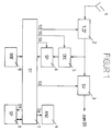
- FIG. 1 shows a block diagram of a video recorder which has a receiving part 2 connected to an antenna 1, a signal processing circuit 3, a display unit 4, a television text decoder 5, a television text page memory 6, a control circuit 7, an operating unit 8 and a desired program memory 9.
- the control circuit 7 which is implemented by a microcomputer, serves to control the operation of the aforementioned circuits 2, 3, 4, 5, 6 and 9, which is indicated by the control lines S2, S3, S4, S5, S6 and S9.
- the high-frequency video signal received by the antenna 1 is fed to the receiving part 2, which has a tuner and an IF amplifier.
- An FBAS signal is available at the output of receiver section 2. This is converted in the signal processing circuit 3 into a component signal, for example an RGB signal.
- the component signal obtained at the output of the signal processing circuit 3 is fed to a television receiver connected to the video recorder and displayed on its screen, if necessary after conversion back into an FBAS signal.
- the television text signals transmitted in the vertical blanking gaps are separated from the CVBS signal available in the output of the receiving part 2 in the television text decoder 5 and the television text data associated with a television text page are temporarily stored in a television text page memory 6.
- the programming of the video recorder for recording a desired television program takes place as follows:
- the control unit 8 is used first to select the video recorder channel in which a program preview page containing the desired television program is transmitted, and then the program preview page itself. This causes the television text data of the aforementioned program preview page to be temporarily stored in the television text page memory 6.
- the control circuit 7 then addresses the television text page memory 6 in such a way that the television text data of the first television program contained on the program preview page is first automatically read out and shown on the display 4 in an optically highlighted manner.
- These television text data which are preferably shown flashing on the display 4 for optical highlighting, are the name of the broadcaster, the broadcast date, the start time and, if appropriate, the end time and the title of the broadcast.
- the flashing display of the television text data of the first television program contained on the program preview page is retained for a period of, for example, 2-3 seconds.
- the control circuit 7 the television text page memory 6 in such a way that the television text data of the second television program contained on the program preview page is automatically read out and shown flashing on the display 4 for the duration of 2-3 seconds, etc.
- the control circuit 7 addresses the television text page memory 8 after the temporary storage of the television text data of the selected program preview page in such a way that the television text data of the first television program contained on the program preview page are read out and shown flashing on the display 4.
- This flashing representation of the television text data of the first television program is retained until a forwarding key arranged on the operating unit 8 is actuated.
- the control circuit 7 addressed the control circuit 7 the television text page memory 6 so that the television text data of the second television program contained on the program preview page is read out and displayed on the display 4, etc.
- the user has the possibility of changing the speed at which the television text data of the individual the television broadcasts containing the program preview page are shown one after the other.
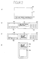
- Preferred embodiments of the display unit 4 used in the programming of the video recorder are described below with reference to FIGS. 2a, 2b, 2c and 2d.
- the flashing display of the television text data which describes the broadcaster, the broadcasting day, the start time and the title, takes place in a text line 42 that is displayed at the bottom of a television receiver screen BS connected to the video recorder.
- the advantage of this embodiment is in particular in that the character size of the alphanumeric characters contained in the text line can be chosen so large that the video recorder programming can, for example, be carried out conveniently from the television chair using a remote control transmitter.
- the remaining area 41 of the screen can be used to display a current one Television program are used, so that it is not necessary to interrupt a television program in progress when programming the video recorder using a television text program preview page.
- the flashing display of the television text data which describes the broadcaster, the broadcasting day, the start time and the title, takes place on an alphanumeric display 43 integrated into the housing of the VCR VCR.
- This is next to a cassette compartment KF1 and keypads TB1 and TB2, which contain the function and numeric keys generally used in video recorders, are arranged on the front of the video recorder.
- the flashing display of the television text data which describes the broadcaster, the broadcasting day, the start time and the title, takes place on a liquid crystal screen 44 attached to the housing of the video record VCR.
- a cassette compartment KF2 and keypads TB3 and TB4 which contain the function and number keys that are generally used in video recorders, are arranged on the front of the video recorder.
- the flashing display of the television text data which shows the broadcaster, the broadcasting day, the start time and describe the title, on an alphanumeric display 45 integrated into the housing of the remote control transmitter FBG of the video recorder.
- the remote control transmitter also has a keypad TB5, which contains the function and numeric keys that are common for remote controls.
- the video recorder has an infrared transmitter (not shown) connected to the control circuit 7, from which the television text data are transmitted to an infrared receiver of the remote control transmitter FBG.
- FIGS. 2b, 2c and 2d The advantages of the configurations shown in FIGS. 2b, 2c and 2d are in particular that the programming of the video recorder using a television text program preview page can be carried out completely independently of the screen of the television receiver connected to the video recorder. It is irrelevant whether a television program is being viewed on the screen of the television receiver during the programming process or whether the television receiver is switched off during this time.
- Another advantageous embodiment of the invention consists in providing a multi-page memory as the television text page memory. Immediately after the connection of the video recorder to a supply voltage, all television text pages containing a program preview are automatically stored in this multi-page memory.
- This embodiment has the particular advantage that the user does not have to enter the page number of the program preview page containing the desired program manually, but can step through all program preview pages step by step by pressing a button provided on the control unit for this purpose.
Claims (8)
- Dispositif pour programmer un magnétoscope, comportant- une unité de commande pour introduire des instructions de commande,- un décodeur de vidéotexte pour séparer, d'un signal d'émission de télévision, les données de vidéotexte contenues dans une page d'annonce de programme et correspondant à plusieurs émissions de télévision,- une mémoire de pages de vidéotexte pour mémoriser temporairement les données indiquées de vidéotexte, et- une mémoire de souhaits de programmes pour mémoriser des données de programmation,caractérisé en ce que- il est prévu un circuit de commande, qui appelle des données à partir de la mémoire de pages de vidéotexte, au moyen d'une sélection correspondante d'adresses de telle sorte que les données de vidéotexte, qui correspondent aux différentes émissions de télévision, sont sélectionnées de façon automatique et individuellement successivement pour l'émission, et- les données de vidéotexte de l'émission individuelle de télévision, sélectionnée respectivement à partir de la page d'annonces de programme mémorisée temporairement, peuvent étre représentées, d'une manière rehaussée du point de vue optique, pendant une durée de l'ordre de plusieurs secondes, et sans interruption d'une émission de télévision en cours, sur une unité d'affichage.
- Dispositif pour programmer un magnétoscope, comportant- une unité de commande pour introduire des instructions de commande,- un décodeur de vidéotexte pour séparer, d'un signal d'émission de télévision, les données de vidéotexte contenues dans une page d'annonce de programme et correspondant à plusieurs émissions de télévision,- une mémoire de pages de vidéotexte pour mémoriser temporairement les données indiquées de vidéotexte, et- une mémoire de souhaits de programmes pour mémoriser des données de programmation,caractérisé en ce que- il est prévu un circuit de commande, qui appelle des données à partir de la mémoire de pages de vidéotexte, au moyen d'une sélection correspondante d'adresses de telle sorte que les données de vidéotexte, qui correspondent à des émissions individuelles de télévision, sont sélectionnées individuellement successivement pour l'émission, sous la commande de l'unité de commande, et- les données de vidéotexte de l'émission individuelle de télévision, sélectionnée respectivement à partir de la page d'annonces de programme mémorisée temporairement, peuvent ètre représentées, d'une manière rehaussée du point de vue optique et sans interruption d'une émission de télévision en cours, sur une unité d'affichage.
- Dispositif selon la revendication 1 ou 2, caractérisé en ce que l'unité d'affichage est l'écran d'un récepteur de télévision raccordé au magnétoscope, et la représentation, rehaussée du point de vue optique, des données de vidéotexte s'effectue sur une ligne d'écriture, insérée dans une mémoire de télévision, au niveau du bord inférieur de l'écran.
- Dispositif selon la revendication 1 ou 2, caractérisé en ce que l'unité d'affichage est un dispositif d'affichage alphanumérique intégré dans le boîtier du magnétoscope.
- Dispositif selon la revendication 1 ou 2, caractérisé en ce que l'unité d'affichage est un écran à cristal liquide, qui est fixé au boîtier du magnétoscope.
- Dispositif selon la revendication 1 ou 2, caractérisé en ce que les données de vidéotexte sont transmises par un émetteur à infrarouge du magnétoscope à un récepteur à infrarouge du générateur de télécommande du magnétoscope et sont représentées sur un dispositif d'affichage alphanumérique intégré dans le boîtier du générateur de télécommande.
- Dispositif selon une ou plusieurs des revendications précédentes, caractérisé par le fait que les données de vidéotexte, qui sont représentées sur l'unité d'affichage, sont représentées avec un clignotement.
- Dispositif selon une ou plusieurs des revendications précédentes, caractérisé en ce que la mémoire de pages de vidéotexte est une mémoire à plusieurs pages, dans laquelle, après le raccordement du magnétoscope à une tension d'alimentation, toutes les pages de vidéotexte, qui contiennent une annonce de programme, sont mémorisées automatiquement.
Applications Claiming Priority (2)
| Application Number | Priority Date | Filing Date | Title |
|---|---|---|---|
| DE4018368A DE4018368C1 (fr) | 1990-06-08 | 1990-06-08 | |
| DE4018368 | 1990-06-08 |
Publications (2)
| Publication Number | Publication Date |
|---|---|
| EP0460520A1 EP0460520A1 (fr) | 1991-12-11 |
| EP0460520B1 true EP0460520B1 (fr) | 1995-08-30 |
Family
ID=6408034
Family Applications (1)
| Application Number | Title | Priority Date | Filing Date |
|---|---|---|---|
| EP91108774A Expired - Lifetime EP0460520B1 (fr) | 1990-06-08 | 1991-05-29 | Dispositif de contrôle de programme d'un magnetoscope utilisant une page de prochaines émissions de vidéotexte |
Country Status (3)
| Country | Link |
|---|---|
| EP (1) | EP0460520B1 (fr) |
| AT (1) | ATE127304T1 (fr) |
| DE (2) | DE4018368C1 (fr) |
Families Citing this family (9)
| Publication number | Priority date | Publication date | Assignee | Title |
|---|---|---|---|---|
| DE4115051A1 (de) * | 1991-05-08 | 1992-11-12 | Grundig Emv | Verfahren zur auswahl einer betriebsweise bei einem geraet der unterhaltungselektronik |
| DE4129571C2 (de) * | 1991-09-06 | 2002-02-07 | Clemens Croy | Vorrichtung zum Programmieren von Aufzeichnungsgeräten |
| FR2713864B1 (fr) * | 1993-12-15 | 1996-02-02 | Henley Trading Ltd | Système de gestion de programmes de télévision. |
| DE4410547C2 (de) * | 1994-03-26 | 1999-03-18 | Loewe Opta Gmbh | Verfahren zur Erstellung einer elektronischen Programmzeitschrift und Schaltung hierfür |
| WO1995028055A1 (fr) † | 1994-04-08 | 1995-10-19 | Prevue International, Inc. | Guide de programmation de defilement interactif |
| KR100348915B1 (ko) † | 1994-05-12 | 2002-12-26 | 마이크로소프트 코포레이션 | 텔레비젼프로그램선택방법및그시스템 |
| DE19519132A1 (de) * | 1995-05-30 | 1996-12-05 | Thomson Brandt Gmbh | System aus einem Fernsehempfänger und einer Fernbedieneinheit |
| US5682206A (en) * | 1995-09-25 | 1997-10-28 | Thomson Consumer Electronics, Inc. | Consumer interface for programming device |
| EP0951016B1 (fr) * | 1998-04-15 | 2004-07-14 | Daewoo Electronics Co., Ltd | Méthode pour vérifier rapidement une minuterie d'un enregistreur à cassette vidéo et enrégistreur à cassette vidéo de mise en oeuvre du méthode |
Family Cites Families (6)
| Publication number | Priority date | Publication date | Assignee | Title |
|---|---|---|---|---|
| JPS6169266A (ja) * | 1984-09-12 | 1986-04-09 | Sharp Corp | 入力装置 |
| DE3533707A1 (de) * | 1985-09-21 | 1987-03-26 | Thomson Brandt Gmbh | Mit hilfe von videotextsignalen programmierbarer videorecorder |
| JPH0816997B2 (ja) * | 1985-12-27 | 1996-02-21 | ソニー株式会社 | 映像再生装置の遠隔操作装置及び映像再生システム |
| DE3641864A1 (de) * | 1986-12-08 | 1988-06-16 | Grundig Emv | Einrichtung zur programmierung eines videorecorders |
| ES2110944T3 (es) * | 1987-07-20 | 1998-03-01 | Koninkl Philips Electronics Nv | Sistema de transmision de television. |
| DE3742468C1 (de) * | 1987-12-15 | 1988-10-06 | Standard Elektrik Lorenz Ag | Videoaufzeichnungsgeraet mit einem Programmwunschspeicher |
-
1990
- 1990-06-08 DE DE4018368A patent/DE4018368C1/de not_active Expired - Fee Related
-
1991
- 1991-05-29 DE DE59106347T patent/DE59106347D1/de not_active Expired - Lifetime
- 1991-05-29 EP EP91108774A patent/EP0460520B1/fr not_active Expired - Lifetime
- 1991-05-29 AT AT91108774T patent/ATE127304T1/de not_active IP Right Cessation
Also Published As
| Publication number | Publication date |
|---|---|
| DE4018368C1 (fr) | 1991-01-24 |
| ATE127304T1 (de) | 1995-09-15 |
| DE59106347D1 (de) | 1995-10-05 |
| EP0460520A1 (fr) | 1991-12-11 |
Similar Documents
| Publication | Publication Date | Title |
|---|---|---|
| DE69714712T3 (de) | Verfahren zur anzeige von fernsehprogrammen und dazugehörigem text | |
| DE3527939C2 (fr) | ||
| DE3640436C3 (de) | Fernbedienung für ein Empfangsgerät der Unterhaltungselektronik | |
| DE10323260B4 (de) | Digitaler Fernseher und Verfahren zum automatischen Umschalten der Kanäle | |
| DE4217246A1 (de) | Videogerät zur Verarbeitung von Zusatzsignalen, welche in den Austastlücken von Fernsehsignalen übertragen werden | |
| DE4240187A1 (de) | Verfahren zum Anzeigen von aus Videotextsignalen gewonnenen Informationen auf einem Bildschirm und Vorrichtung zur Durchführung des Verfahrens | |
| WO1993005452A1 (fr) | Dispositif et procede pour la programmation de magnetoscopes | |
| DE4121314A1 (de) | Schaltungsanordnung zur automatischen bild-im-bild-wiedergabe von proben aus fernsehkanaelen | |
| DE4023866C2 (fr) | ||
| DE4106246C1 (en) | TV broadcast suppression appts. esp. for avoiding advertisements - stores images which start and end of broadcast and compares current image with memory to control suppression or channel change | |
| EP0460520B1 (fr) | Dispositif de contrôle de programme d'un magnetoscope utilisant une page de prochaines émissions de vidéotexte | |
| WO1990010351A1 (fr) | Procede de surimpression de titres pendant une emission de television | |
| EP0373297A2 (fr) | Enregistreur vidéo avec décodeur de télétexte | |
| DE69830699T2 (de) | Empfänger für digitale Sendungen | |
| DE4135628C2 (de) | Einrichtung für die Anzeige einer programmierten Aufnahme | |
| EP0525559B1 (fr) | Méthode et dispositif pour la réception de télétexte avec diminution des temps d'attente lors de l'affichage de pages de télétexte | |
| DE19509383A1 (de) | Verfahren zum Abrufen von Informationen aktueller Hörfunk- oder Fernsehsendungen | |
| DE3735780A1 (de) | Verfahren zur programmierung eines empfaengers mit videorecorder zur aufzeichnung von ueber satellit uebertragenen fernsehprogrammbeitraegen | |
| EP0512206B1 (fr) | Procédé pour choisir un mode de fonctionnement d'un appareil de divertissement | |
| DE3907098A1 (de) | Verfahren und schaltungsanordnung zur sendeseitigen steuerung eines empfaengers | |
| DE19733016B4 (de) | Fernsehgerät mit variabler Darstellung von Fernsehbild und Zusatzinformationen | |
| EP0478926B1 (fr) | Dispositif de réception de signaux de télévision pour la réception de signaux de télévision à plusieurs canaux linguistiques | |
| EP0524563B1 (fr) | Méthode et dispositif pour la réception de télétexte avec diminution des temps d'attente lors de l'affichage de pages de télétexte | |
| DE19924196C2 (de) | Verfahren und Einrichtung zum Bereitstellen eines EPG in einem analogen Fernsehempfänger | |
| DE4438412C2 (de) | Vorrichtung zur Fernsehprogrammumschaltung unter Verwendung eines Fernsehtextdecoders |
Legal Events
| Date | Code | Title | Description |
|---|---|---|---|
| PUAI | Public reference made under article 153(3) epc to a published international application that has entered the european phase |
Free format text: ORIGINAL CODE: 0009012 |
|
| AK | Designated contracting states |
Kind code of ref document: A1 Designated state(s): AT DE FR GB IT |
|
| 17P | Request for examination filed |
Effective date: 19920313 |
|
| 17Q | First examination report despatched |
Effective date: 19940407 |
|
| RAP1 | Party data changed (applicant data changed or rights of an application transferred) |
Owner name: GRUNDIG E.M.V. ELEKTRO-MECHANISCHE VERSUCHSANSTALT |
|
| GRAA | (expected) grant |
Free format text: ORIGINAL CODE: 0009210 |
|
| AK | Designated contracting states |
Kind code of ref document: B1 Designated state(s): AT DE FR GB IT |
|
| REF | Corresponds to: |
Ref document number: 127304 Country of ref document: AT Date of ref document: 19950915 Kind code of ref document: T |
|
| REF | Corresponds to: |
Ref document number: 59106347 Country of ref document: DE Date of ref document: 19951005 |
|
| GBT | Gb: translation of ep patent filed (gb section 77(6)(a)/1977) |
Effective date: 19950915 |
|
| ET | Fr: translation filed | ||
| ITF | It: translation for a ep patent filed |
Owner name: STUDIO JAUMANN |
|
| PLBE | No opposition filed within time limit |
Free format text: ORIGINAL CODE: 0009261 |
|
| STAA | Information on the status of an ep patent application or granted ep patent |
Free format text: STATUS: NO OPPOSITION FILED WITHIN TIME LIMIT |
|
| 26N | No opposition filed | ||
| REG | Reference to a national code |
Ref country code: FR Ref legal event code: TP |
|
| REG | Reference to a national code |
Ref country code: GB Ref legal event code: IF02 |
|
| REG | Reference to a national code |
Ref country code: GB Ref legal event code: 732E |
|
| REG | Reference to a national code |
Ref country code: FR Ref legal event code: TP |
|
| PGFP | Annual fee paid to national office [announced via postgrant information from national office to epo] |
Ref country code: AT Payment date: 20090521 Year of fee payment: 19 Ref country code: IT Payment date: 20090522 Year of fee payment: 19 |
|
| PGFP | Annual fee paid to national office [announced via postgrant information from national office to epo] |
Ref country code: FR Payment date: 20100617 Year of fee payment: 20 |
|
| PGFP | Annual fee paid to national office [announced via postgrant information from national office to epo] |
Ref country code: DE Payment date: 20100602 Year of fee payment: 20 |
|
| PGFP | Annual fee paid to national office [announced via postgrant information from national office to epo] |
Ref country code: GB Payment date: 20100524 Year of fee payment: 20 |
|
| PG25 | Lapsed in a contracting state [announced via postgrant information from national office to epo] |
Ref country code: AT Free format text: LAPSE BECAUSE OF NON-PAYMENT OF DUE FEES Effective date: 20100529 |
|
| PG25 | Lapsed in a contracting state [announced via postgrant information from national office to epo] |
Ref country code: IT Free format text: LAPSE BECAUSE OF NON-PAYMENT OF DUE FEES Effective date: 20100529 |
|
| REG | Reference to a national code |
Ref country code: DE Ref legal event code: R071 Ref document number: 59106347 Country of ref document: DE |
|
| REG | Reference to a national code |
Ref country code: GB Ref legal event code: PE20 Expiry date: 20110528 |
|
| PG25 | Lapsed in a contracting state [announced via postgrant information from national office to epo] |
Ref country code: GB Free format text: LAPSE BECAUSE OF EXPIRATION OF PROTECTION Effective date: 20110528 |
|
| PG25 | Lapsed in a contracting state [announced via postgrant information from national office to epo] |
Ref country code: DE Free format text: LAPSE BECAUSE OF EXPIRATION OF PROTECTION Effective date: 20110530 |