EP0457306A2 - Method and device to read and write a data memory driven by a microprocessor, especially for a measuring or counting recording device - Google Patents
Method and device to read and write a data memory driven by a microprocessor, especially for a measuring or counting recording device Download PDFInfo
- Publication number
- EP0457306A2 EP0457306A2 EP91107872A EP91107872A EP0457306A2 EP 0457306 A2 EP0457306 A2 EP 0457306A2 EP 91107872 A EP91107872 A EP 91107872A EP 91107872 A EP91107872 A EP 91107872A EP 0457306 A2 EP0457306 A2 EP 0457306A2
- Authority
- EP
- European Patent Office
- Prior art keywords
- data
- head
- read
- scanning head
- data memory
- Prior art date
- Legal status (The legal status is an assumption and is not a legal conclusion. Google has not performed a legal analysis and makes no representation as to the accuracy of the status listed.)
- Withdrawn
Links
- 230000015654 memory Effects 0.000 title claims abstract description 44
- 238000000034 method Methods 0.000 title claims abstract description 27
- 230000006698 induction Effects 0.000 claims abstract description 48
- 230000005540 biological transmission Effects 0.000 claims abstract description 42
- 230000003287 optical effect Effects 0.000 claims abstract description 28
- 230000001939 inductive effect Effects 0.000 claims description 24
- 238000013500 data storage Methods 0.000 claims description 9
- 239000013256 coordination polymer Substances 0.000 claims description 8
- 238000011156 evaluation Methods 0.000 claims description 8
- 230000005693 optoelectronics Effects 0.000 claims description 6
- 239000004020 conductor Substances 0.000 claims description 4
- 230000005291 magnetic effect Effects 0.000 claims description 3
- 239000003990 capacitor Substances 0.000 description 14
- 238000010586 diagram Methods 0.000 description 3
- 230000006870 function Effects 0.000 description 3
- 238000010438 heat treatment Methods 0.000 description 3
- 239000013078 crystal Substances 0.000 description 2
- 238000004020 luminiscence type Methods 0.000 description 2
- 238000005259 measurement Methods 0.000 description 2
- 239000010453 quartz Substances 0.000 description 2
- VYPSYNLAJGMNEJ-UHFFFAOYSA-N silicon dioxide Inorganic materials O=[Si]=O VYPSYNLAJGMNEJ-UHFFFAOYSA-N 0.000 description 2
- 230000001960 triggered effect Effects 0.000 description 2
- 230000003321 amplification Effects 0.000 description 1
- 238000013459 approach Methods 0.000 description 1
- 230000002457 bidirectional effect Effects 0.000 description 1
- 238000004891 communication Methods 0.000 description 1
- 238000010276 construction Methods 0.000 description 1
- 230000008878 coupling Effects 0.000 description 1
- 238000010168 coupling process Methods 0.000 description 1
- 238000005859 coupling reaction Methods 0.000 description 1
- 238000013461 design Methods 0.000 description 1
- 230000005611 electricity Effects 0.000 description 1
- 230000007613 environmental effect Effects 0.000 description 1
- 239000003302 ferromagnetic material Substances 0.000 description 1
- 238000003199 nucleic acid amplification method Methods 0.000 description 1
- 238000012545 processing Methods 0.000 description 1
- 238000012360 testing method Methods 0.000 description 1
- 238000012549 training Methods 0.000 description 1
- XLYOFNOQVPJJNP-UHFFFAOYSA-N water Substances O XLYOFNOQVPJJNP-UHFFFAOYSA-N 0.000 description 1
Images


Classifications
-
- H04B5/77—
-
- G—PHYSICS
- G01—MEASURING; TESTING
- G01R—MEASURING ELECTRIC VARIABLES; MEASURING MAGNETIC VARIABLES
- G01R15/00—Details of measuring arrangements of the types provided for in groups G01R17/00 - G01R29/00, G01R33/00 - G01R33/26 or G01R35/00
- G01R15/14—Adaptations providing voltage or current isolation, e.g. for high-voltage or high-current networks
- G01R15/22—Adaptations providing voltage or current isolation, e.g. for high-voltage or high-current networks using light-emitting devices, e.g. LED, optocouplers
-
- G—PHYSICS
- G06—COMPUTING; CALCULATING OR COUNTING
- G06M—COUNTING MECHANISMS; COUNTING OF OBJECTS NOT OTHERWISE PROVIDED FOR
- G06M3/00—Counters with additional facilities
-
- G—PHYSICS
- G08—SIGNALLING
- G08C—TRANSMISSION SYSTEMS FOR MEASURED VALUES, CONTROL OR SIMILAR SIGNALS
- G08C17/00—Arrangements for transmitting signals characterised by the use of a wireless electrical link
- G08C17/04—Arrangements for transmitting signals characterised by the use of a wireless electrical link using magnetically coupled devices
Landscapes
- Physics & Mathematics (AREA)
- General Physics & Mathematics (AREA)
- Engineering & Computer Science (AREA)
- Theoretical Computer Science (AREA)
- Computer Networks & Wireless Communication (AREA)
- Arrangements For Transmission Of Measured Signals (AREA)
- Near-Field Transmission Systems (AREA)
Abstract
Description
Die Erfindung betrifft ein Verfahren zum Auslesen und/oder Einlesen von Daten an einem mikroprozessorgesteuerten Datenspeicher, insbesondere eines registrierenden Meß- oder Zählgerätes, bei dem die Daten zwischen dem Datenspeicher und einer Ein- Auslesevorrichtung über eine Schnittstelle mit drahtloser Signalverbindung übertragen werden.The invention relates to a method for reading and / or reading data in a microprocessor-controlled data memory, in particular a registering measuring or counting device, in which the data are transmitted between the data memory and a read-in device via an interface with a wireless signal connection.
Bei bestimmten registrierenden Meß- oder Zählgeräten, insbesondere bei Verbrauchszählern für Fernwärme, Gas und Wasser, aber auch beispielsweise bei der Datenerfassung von Umweltschutzstationen, ergibt sich die Aufgabe, daß die im Zähler gespeicherten Verbrauchsdaten in vorgegebenen Zeitabständen abgelesen werden müssen. Es ist bereits bekanntgeworden, anstelle der umständlichen Ablesung eines Zählerstandes durch eine Person mit dem notwendigen Eintragen des abgelesenen Zählerstandes von Hand ein automatisches Verfahren einzusetzen, mit dem bei Zählern, die einen mikropozessorgesteuerten Datenspeicher enthalten, die Daten über eine Schnittstelle mit drahtloser Signalverbindung direkt auf eine Ein- Auslesevorrichtung übertragen werden. Eine bekannte Einrichtung hierzu enthält einen an elektronische Auswerte- und Eingabeeinheiten angeschlossenen optischen Abtastkopf mit optoelektronischen Wandlern zur Abgabe und Aufnahme von optischen Signalen, während der Datenspeicher des Zählers mit einem entsprechenden optischen Sendekopf mit optoelektronischen Wandlern ausgerüstet ist und die Schnittstelle durch eine räumliche Annäherung von Abtastkopf und Sendekopf zur Erzielung eines optischen Signalweges gebildet wird. Die den Zähler ablesende Person braucht dann lediglich den optischen Abtastkopf einer mitgeführten tragbaren Ein-Auslesevorrichtung an eine vorgegebene Stelle an der Außenwand des Zählergehäuses anzusetzen, hinter der sich der Sendekopf befindet, und es können dann alle Daten automatisch übertragen werden. Ein hierbei auftretendes Problem besteht darin, daß das Auslesen von Daten in der oben beschriebenen Weise auf der Seite des Zählers einen Anteil an elektrischer Energie erfordert, der wesentlich größer ist als der im normalen Betrieb auftretende Energieanteil. Dies ist bei allen Zählern, die nicht, wie etwa Elektrizitätszähler, von Natur aus an eine elektrische Leitung angeschlossen sind, sondern, wie beispielsweise Zähler zur Fernwärmezählung oder zur Gaszählung, eine Batterie als elektrische Energiequelle besitzen, eine erhebliche Belastung dieser Batterie, die dazu führt, daß die Batterien relativ häufig ausgewechselt werden müssen. Dies ist insbesondere dann unerwünscht, wenn die Zeitabstände, in denen die Batterie ausgewechselt werden muß, kleiner sind als der Eichzeitraum des Zählers, da die Batterie sich innerhalb des plombierten Teils des Zählers befindet und jeder Eingriff in den Zähler während des Eichzeitraumes unerwünscht ist. Es wird daher angestrebt, daß die Lebensdauer der Batterie eines derartigen Zählers nach Möglichkeit mindestens so groß sein soll wie der Eichzeitraum.With certain registering measuring or counting devices, in particular with consumption meters for district heating, gas and water, but also, for example, with data acquisition from environmental protection stations, the task arises that the consumption data stored in the meter must be read at predetermined time intervals. It has already become known, instead of the cumbersome reading of a meter reading by one person with the necessary entry of the read meter reading by hand to use an automatic method with which the meters in meters which contain a microprocessor-controlled data memory are transmitted directly to a read-in device via an interface with a wireless signal connection. A known device for this purpose contains an optical scanning head connected to electronic evaluation and input units with optoelectronic transducers for delivering and receiving optical signals, while the data memory of the meter is equipped with a corresponding optical transmission head with optoelectronic transducers and the interface by spatial proximity of the scanning head and transmitter head is formed to achieve an optical signal path. The person reading the meter then only needs to place the optical scanning head of a portable read-in device carried along at a predetermined location on the outer wall of the meter housing, behind which the transmitter head is located, and all data can then be transmitted automatically. A problem that arises in this case is that the reading out of data in the manner described above requires a portion of electrical energy on the meter side which is substantially greater than the portion of energy occurring in normal operation. For all meters that are not naturally connected to an electrical line, such as electricity meters, but, like meters for district heating or gas metering, that have a battery as an electrical energy source, this battery is considerably stressed, which leads to this that the batteries have to be replaced relatively often. This is particularly undesirable when the intervals in which the battery must be replaced, are shorter than the calibration period of the meter, since the battery is located within the sealed part of the meter and any intervention in the meter is undesirable during the calibration period. It is therefore desirable that the life of the battery of such a meter should be at least as long as possible as the calibration period.
Der Erfindung liegt die Aufgabe zugrunde, ein Verfahren der eingangs und im Oberbegriff des Patentanspruchs 1 angegebenen Art zu schaffen, mit dem es möglich ist, insbesondere das Auslesen von Daten in einer Weise durchzuführen, die die Spannungsquelle des mikroprozessorgesteuerten Datenspeichers nicht belastet. Weiterhin sollte eine Einrichtung zur Durchführung dieses Verfahrens geschaffen werden, die einfach aufgebaut und in sehr einfacher und sicherer Weise handhabbar ist.The invention has for its object to provide a method of the type specified in the preamble of
Die Lösung dieser Aufgabe erfolgt erfindungsgemäß mit den Merkmalen aus dem kennzeichnenden Teil des Patentanspruchs 1. Vorteilhafte Ausführungsformen des erfindungsgemäßen Verfahrens sind in den Patentansprüchen 2 und 3 beschrieben.This object is achieved according to the invention with the features from the characterizing part of
Eine besonders vorteilhafte Einrichtung zur Durchführung des erfindungsgemäßen Verfahrens, bei der die Datenübertragung zwischen dem Datenspeicher und der Ein- Auslesevorrichtung über eine Schnittstelle mit einem optischen Signalweg erfolgt, ist in Patentanspruch 4 beschrieben. Vorteilhafte Ausführungsformen dieser Einrichtung sind Gegenstand der Patentansprüche 5 bis 7. Weitere Ausführungsbeispiele von Einrichtungen zur Durchführung des erfindungsgemäßen Verfahrens sind in den Ansprüchen 8 bis 12 beschrieben.A particularly advantageous device for carrying out the method according to the invention, in which the data transmission between the data memory and the read-in device takes place via an interface with an optical signal path, is described in
Der Grundgedanke der Erfindung besteht darin, nicht nur das Auslesen oder Einlesen von Daten zwischen Datenspeicher und Ein- und Auslesevorrichtung über eine Schnittstelle mit drahtloser Signalverbindung durchzuführen, sondern auch die insbesondere zum Auslesen erforderliche Energie drahtlos von außen, also von der Ein- Auslesevorrichtung her, zuzuführen. Auf diese Weise wird eine Belastung der Spannungsquelle des Datenspeichers während des Auslesevorgangs vermieden. Die Energiezuführung mittels eines Hochfrequenzsignals auf induktivem Wege hat sich hierbei als besonders einfach zu handhaben und vorteilhaft erwiesen. Insbesondere im Zusammenhang mit einer Einrichtung, bei der die Ein-Auslesevorrichtung einen optischen Abtastkopf besitzt und somit die Datenübertragung über einen optischen Weg erfolgt, führt das Verfahren mit induktiver Energieübertragung zu besonders einfachen und leicht zu handhabenden Einrichtungen. Hierbei ist es auch möglich, in mindestens einer Richtung über die drahtlose Energieverbindung auf induktivem Wege zusätzliche Daten durch entsprechende Modulation des Hochfrequenzsignals zu übertragen. Dies kann beispielsweise mittels eines frequenzmodulierten Trägersignals erfolgen. Auf diese Weise entsteht ohne Beeinflussung der Energieübertragung ein zusätzlicher Datenkanal, der von der optischen Übertragungsstrecke unabhängig ist. Die Schnittstelle kann nur in Betrieb genommen werden, wenn das Hochfrequenz-Trägersignal anliegt. Hierdurch wird ein zusätzlicher Schutz gegen eine unbefugte Datenmanipulation erzielt.The basic idea of the invention is not only to read or read data between the data storage device and the read-in and read-out device via an interface with a wireless signal connection, but also to wirelessly transmit the energy required in particular for reading from outside, that is to say from the read-in device. feed. In this way, stress on the voltage source of the data storage device during the readout process is avoided. The supply of energy by means of a high-frequency signal by induction has proven to be particularly easy to use and advantageous. In particular in connection with a device in which the read-in device has an optical scanning head and thus the data is transmitted via an optical path, the method with inductive energy transmission leads to particularly simple and easy-to-use devices. Here, it is also possible to transmit additional data in an inductive way via the wireless energy connection in at least one direction by appropriate modulation of the high-frequency signal. This can be done, for example, by means of a frequency-modulated carrier signal. In this way, an additional data channel is created without influencing the energy transmission, which is independent of the optical transmission path. The interface can only be put into operation if the high-frequency carrier signal is present. This provides additional protection against unauthorized data manipulation.
Selbstverständlich ist es aber auch möglich, das erfindungsgemäße Verfahren im Zusammenhang mit einer Datenübertragung auf rein induktivem Wege durchzuführen.Of course, however, it is also possible to carry out the method according to the invention in connection with data transmission in a purely inductive way.
Das erfindungsgemäße Verfahren ist vor allem zum Ablesen von Wärmezählern, Gaszählern und dergleichen gedacht, es ist aber auch zum Ablesen von anderen extern ablesbaren Datenspeichern verwendbar und kann auch bei Zählern verwendet werden, die an eine eigene elektrische Energieversorgung angeschlossen sind. Letzteres hat den Vorteil, daß Ein- Auslesevorrichtungen geschaffen werden können, die bei sehr unterschiedlichen, mit genormten Ableseeinrichtungen versehenen Zählertypen verwendet werden können. Diese Art der drahtlosen Energiezuführung zum Auslesen von Daten hat den zusätzlichen Vorteil, daß durch das Annähern des Abtastkopfes der Ein-Auslesevorrichtung an den Sendekopf und dem damit verbundenen Anlegen der Betriebsspannung an die Ausleseeinheit des Datenspeichers bei einem Zählerprozessor ein sogenannter "Hardware-Interrupt" ausgelöst werden kann. Daraufhin beendet dieser Prozessor das Messen und führt die Datenkommunikation über die drahtlose Schnittstelle aus. Eine in bestimmten Zeitabständen wiederkehrende Unterbrechung der Messung,um zu kontrollieren, ob Informationen an der Schnittstelle anliegen, ist dadurch nicht mehr notwendig. Ebenso kann eine aufwendige Zeitsynchronisation zwischen Auslesegerät und Auslesezähler entfallen.The method according to the invention is primarily intended for reading heat meters, gas meters and the like, but it can also be used for reading other externally readable data memories and can also be used with meters that are connected to their own electrical power supply. The latter has the advantage that reading devices can be created which can be used with very different types of meter provided with standardized reading devices. This type of wireless energy supply for reading data has the additional advantage that a so-called "hardware interrupt" is triggered by the approach of the scanning head of the read-in device to the sending head and the associated application of the operating voltage to the reading unit of the data memory in a counter processor can be. This processor then ends the measurement and carries out data communication via the wireless interface. A recurring interruption of the measurement in order to check whether information is present at the interface is no longer necessary. A complex time synchronization between the reading device and reading counter can also be omitted.
Die Anwendung des erfindungsgemäßen Verfahrens und der erfindungsgemäßen Einrichtungen ist aber nicht auf das Ablesen von Zählern beschränkt. Vielmehr kann auch die Dateneingabe in die Datenspeicher von registrierenden Meß- oder Zählgeräten mit Energiezuführung von außen über die drahtlose Schnittstelle durchgeführt werden, beispielsweise bei der Prüfung der Zählgeräte oder um bestimmte Steuerfunktionen auszuüben. Somit ist auch bei diesem stromintensiven Arbeiten eine Unterstützung der Batterie des Datenspeichers möglich.However, the use of the method and the devices according to the invention is not limited to reading meters. Rather, the data can also be entered into the data memories of registering measuring or counting devices with external energy supply via the wireless interface, for example when checking the counting devices or in order to perform certain control functions. This enables the battery of the data storage device to be supported even with this electricity-intensive work.
Weiterhin ist das erfindungsgemäße Verfahren und die Einrichtungen hierzu nicht nur auf die Verwendung an Zählern beschränkt, sondern kann auch bei anderen mikroprozessorgesteuerten Datenspeichern verwendet werden, bei denen die Übertragung von Daten an eine externe Ein-Auslesevorrichtung über eine Schnittstelle mit drahtloser Signalverbindung erfolgt.Furthermore, the method according to the invention and the devices for this purpose are not only limited to use on meters, but can also be used in other microprocessor-controlled data memories in which the transmission of data to an external read-in device takes place via an interface with a wireless signal connection.
Das erfindungsgemäße Verfahren hat weiterhin den Vorteil, daß der mikroprozessorgesteuerte Datenspeicher bzw. der ganze diesen Datenspeicher enthaltende Zähler räumlich relativ weit von der Schnittstelle zur Datenübertragung entfernt sein kann, weil infolge des erfindungsgemäßen Verfahrens der Energiezuführung relativ große Leitungslängen zwischen der Schnittstelle und dem Datenspeicher in Kauf genommen werden können.The method according to the invention also has the advantage that the microprocessor-controlled data memory or the entire counter containing this data memory can be spatially relatively far away from the interface for data transmission, because due to the inventive method of supplying energy relatively long line lengths between the interface and the data memory are available can be taken.
Bei einer Ausführungsform der erfindungssgemäßen Einrichtung, mit welcher sowohl die Energieübertragung als auch die Datenübertragung auf rein induktivem Wege durchgeführt wird, können am Abtastkopf und am Sendekopf jeweils mehrere Induktionsspulen konzentrisch ineinander angeordnet sein. Bei einer Anordnung von jeweils drei Induktionsspulen in dieser Weise werden drei voneinander unabhängige Übertragungskanäle erhalten, von denen einer zur Übertragung der Energie, ein weiterer zur Übertragung von Daten in einer Richtung und der dritte zur Übertragung von Daten in der Gegenrichtung ausgenutzt werden können. Andererseits ist es aber auch möglich, durch entsprechende schaltungstechnische Maßnahmen mehrere Übertragungskanäle mit einer Anzahl von Induktionsspulen zu erhalten, die kleiner ist als die Anzahl der Übertragungskanäle.In one embodiment of the device according to the invention, with which both the energy transmission and the data transmission are carried out in a purely inductive way, several induction coils can be arranged concentrically one inside the other on the scanning head and on the transmitting head. With an arrangement of three induction coils in this way, three mutually independent transmission channels are obtained, one of which can be used for transmitting the energy, another for transmitting data in one direction and the third for transmitting data in the opposite direction. On the other hand, however, it is also possible to obtain a plurality of transmission channels with a number of induction coils that are smaller than the number of transmission channels by appropriate circuitry measures.
Im Folgenden wird anhand der beigefügten Zeichnungen ein Ausführungsbeispiel des erfindungsgemäßen Verfahrens und einer Einrichtung zur Durchführung des Verfahrens näher erläutert.An exemplary embodiment of the method according to the invention and a device for carrying out the method are explained in more detail below with reference to the accompanying drawings.
In den Zeichnungen zeigen:
- Fig. 1
- in einer stark schematisierten Darstellung einen Zähler mit einer daran angesetzten Ein- Auslesevorrichtung;
- Fig. 2
- in einem Blockschaltbild die wichtigsten Schaltelemente der Einrichtung nach Fig. 1, die zur drahtlosen Energieversorgung dienen;
- Fig. 3
- in einem Schaltbild die auf Seiten des Zählers notwendigen Schaltungseinrichtungen zur Energie- und Datenübertragung;
- Fig. 4
- in einer Darstellung analog Fig. 2 eine Variante der Einrichtung nach Fig. 1 mit zusätzlicher Datenübertragung auf induktivem Wege;
- Fig. 5
- in einer Darstellung analog Fig. 3 die auf Seiten des Zählers notwendigen Schaltungseinrichtungen bei der Variante nach Fig. 4.
- Fig. 6
- in einem Blockschaltbild die wichtigsten Schaltelemente einer Ein- Auslesevorrichtung in einer Ausführungsform mit nur induktiver Energie- und Datenübertragung;
- Fig. 7
- in einer Darstellung analog Fig. 6 eine Variante der Ausführungsform nach Fig. 6;
- Fig. 8
- in einer schematisierten perspektivischen Darstellung einen Abtastkopf für eine Einrichtung nach Fig. 7.
- Fig. 1
- in a highly schematic representation, a counter with a read-in device attached to it;
- Fig. 2
- in a block diagram the most important switching elements of the device of Figure 1, which are used for wireless power supply.
- Fig. 3
- in a circuit diagram the circuitry necessary for energy and data transmission on the part of the meter;
- Fig. 4
- in a representation analogous to FIG. 2, a variant of the device according to FIG. 1 with additional data transmission by inductive means;
- Fig. 5
- in a representation analogous to FIG. 3, the circuit devices required on the part of the counter in the variant according to FIG. 4.
- Fig. 6
- in a block diagram the most important switching elements of a read-in device in one embodiment with only inductive energy and data transmission;
- Fig. 7
- in a representation analogous to FIG. 6, a variant of the embodiment according to FIG. 6;
- Fig. 8
- in a schematic perspective illustration a scanning head for a device according to FIG. 7.
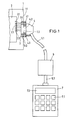
In Fig. 1 ist stark schematisiert ein Zähler beispielsweise zur Fernwärmezählung dargestellt, mit einem Gehäuse 1 und einem mikroprozessorgesteuerten Datenspeicher 2, welcher einen Speiseeingang 2.1, einen Datenausgang 2.2 und einen Dateneingang 2.3 aufweist. Die Ein-Ausgänge 2.1, 2.2 und 2.3 sind mit einem Bauteil 3 verbunden, das im folgenden als "Sendekopf" bezeichnet wird, obwohl über dieses Bauteil Daten in beiden Richtungen übertragen werden. Die Funktion dieses Sendekopfs 3 wird weiter unten näher erläutert. An die Außenseite der Gehäusewand 1.1 ist ein Bauteil 4 lösbar angesetzt, das im folgenden als "Abtastkopf" bezeichnet wird, obwohl durch dieses Bauteil ebenfalls Daten in beiden Richtungen übertragen werden können. Auch die Funktion dieses Bauteils wird weiter unten näher erläutert. Der Abtastkopf 4 besitzt an seiner Vorderseite einen Ringmagnet 4.3 mit dem erreicht wird, daß der auf die aus ferromagnetischem Material bestehende Gehäusewand 1.1 aufgesetzte Abtastkopf 4 dort haftet. Der Abtastkopf 4 ist über eine Leitung 5.1 mit einer Vorrichtung 6 verbunden, die in weiter unten näher beschriebener Weise einen Sender sowie Verstärker enthält. Er ist weiterhin über eine Leitung 5.2 mit einer Vorrichtung 7 verbunden, die Eingabe- und Auswerteeinheiten enthält und an ihrer Oberseite mit einer Tastatur 7.1 und einem Anzeigesichtfeld 7.2 versehen ist. Die Vorrichtungen 4, 6 und 7 bilden zusammen eine Ein-Auslesevorrichtung für den Datenspeicher 2 des Zählers. Die genauere Ausbildung der in der Vorrichtung 7 enthaltenen Auswerte- und Eingabeeinheiten wird im folgenden nicht dargestellt, weil es sich hier um an sich bekannte Schaltungen handelt. Die Übertragung von Daten zwischen dem Datenspeicher 2 und der Ein- Auslesevorrichtung 4-6-7 erfolgt in Richtung vom Datenspeicher 2 aus über den Sendekopf 3, der zu diesem Zweck ein Mittelteil 3.2 aufweist, welches optoelektronische Wandler enthält und dem ein Mittelteil 4.2 am Abtastkopf 4 gegenüberliegt, das entsprechend ebenfalls optoelektronische Wandler enthält, so daß durch eine Öffnung 1.2 in der Gehäusewand 1.1 ein drahtloser, optischer Signalweg zur Übertragung von Daten in beiden Richtungen gebildet wird.In Fig. 1 is a highly schematic, for example, for district heating metering, shown with a
Beim Auslesen von Daten aus dem Datenspeicher 2 wird von der Ein- Auslesevorrichtung aus die notwendige elektrische Energie auf den Datenspeicher 2 übertragen. Hierzu ist am Abtastkopf 4 eine dessen Vorderteil umgebende Induktionsspule 4.1 angeordnet, der an der Innenseite der Gehäusewand 1.1 eine das Mittelteil 3.2 des Sendekopfes 3 umgebende Induktionsspule 3.1 gegenüberliegt. Der Außendurchmesser des Vorderteils des Abtastkopfes 4 kann dabei im Bereich zwischen 25 bis 40mm liegen und beispielsweise 32 mm betragen. Entsprechend ist dann auch der Innendurchmesser der den Abtastkopf 4 umgebenden Induktionsspule 4.1 dimensioniert.When reading data from the
Die schaltungstechnischen Einzelheiten der Einrichtung zur Übertragung der elektrischen Energie über die Induktionsspulen 4.1 und 3.1 werden im folgenden anhand der Fig. 2 und 3 näher erläutert.The circuit details of the device for transmitting the electrical energy via the induction coils 4.1 and 3.1 are explained in more detail below with reference to FIGS. 2 and 3.
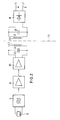
Fig. 2 zeigt auf der linken Seite die Schaltelemente, die der Ein- Auslesevorrichtung zugeordnet sind. Die Induktionsspule 4.1 im Abtastkopf 4, deren Induktivität mit LS bezeichnet ist, bildet zusammen mit einem Kondensator CS einen elektrischen Schwingkreis, der über einen Hauptverstärker V2 und einen Trennverstärker V1 an einen Oszillator G angeschlossen ist, der von einem Schwingquarz Q gesteuert wird. Die Bauteile CS, V2, V1, G und Q sind zweckmäßig innerhalb der Vorrichtung 6 von Fig. 1 angeordnet. Bei entsprechend kleiner Ausbildung der Schaltelemente (surface mounted device) können die Bauteile der Vorrichtung 6 innerhalb des optischen Abtastkopfes 4 angeordnet sein. Selbstverständlich ist es auch möglich, diese Bauelemente innerhalb der Vorrichtung 7 anzuordnen. Die der Induktionsspule 4.1 innerhalb des Gehäuses 1 gegenüberliegende Induktionsspule 3.1 bildet zusammen mit einem Kondensator CE ebenfalls einen elektrischen Schwingkreis, der auf die gleiche Frequenz abgestimmt ist wie der Schwingkreis LS-CS, nämlich auf die Frequenz von z.B. 32,7 kHz des Schwingquarzes Q. Der Schwingkreis LE-CE ist an einen Gleichrichter D angeschlossen, der an seinen Ausgängen SP, die gleichzeitig als die Speiseeingänge der Schnittstelle des Datenspeichers angesehen werden können, eine Gleichspannung an eine Leiterschleife a-b abgibt, deren Verlauf in Fig. 3 näher dargestellt ist.Fig. 2 shows on the left side the switching elements that are assigned to the read-in device. The induction coil 4.1 in the
Fig. 3 zeigt einen Mikrocomputer CP, der in nicht eigens dargestellter Weise einen Mikroprozessor sowie einen Datenspeicher enthält. Der Dateneingang ist an eine Fotodiode PD1 angeschlossen, die im Mittelteil 3.2 des Sendekopfes angeordnet ist. Der Datenausgang ist an die Basis eines Transistors T angeschlossen, der in der Leiterschleife a-b liegt, welche außerdem einen Widerstand R sowie eine im Mittelteil 3.2 des Sendekopfes angeordnete Lumineszenzdiode LD1 enthält. Das dem Mittelteil 3.2 des Sendekopfes gegenüberliegende Mittelteil 4.2 des Abtastkopfes 4 ist ebenfalls in Fig. 3 zu sehen und enthält entsprechend eine Fotodiode PD2 und eine Lumineszenzdiode LD2.Fig. 3 shows a microcomputer CP, which contains a microprocessor and a data memory in a manner not specifically shown. The data input is connected to a photodiode PD1, which is arranged in the middle part 3.2 of the transmission head. The data output is connected to the base of a transistor T, which lies in the conductor loop a-b, which also contains a resistor R and a luminescent diode LD1 arranged in the middle part 3.2 of the transmitter head. The middle part 4.2 of the
Wenn aus dem im Mikrocomputer CP enthaltenen Datenspeicher Daten ausgelesen werden sollen zur Zählerablesung, wird vom Oszillator G ein HF-Signal erzeugt, das nach Verstärkung in den Verstärkern V1 und V2 zum Auskoppelschwingkreis CS, LS gelangt und von der Induktionsspule 4.1 drahtlos weiter auf die Induktionsspule 3.1 und damit den Einkoppelschwingkreis LE-CE übertragen wird. Der Gleichrichter D gibt ein Gleichspannungssignal an die Leiterschleife a-b und damit die Betriebsspannung an den Transistor T, über den nunmehr die Daten ausgelesen werden, die von der Lumineszenzdiode LD1 auf optischem Wege auf die Fotodiode PD2 übertragen werden und in nicht eigens dargestellter Weise dann den in der Vorrichtung 7 angeordneten Auswerte- und Eingabeeinheiten zugeführt werden.If data are to be read from the data memory contained in the microcomputer CP for meter reading, an oscillating signal is generated by the oscillator G after amplification in the amplifiers V1 and V2, it arrives at the decoupling circuit CS, LS and is wirelessly transmitted from the induction coil 4.1 to the induction coil 3.1 and thus the coupling circuit LE-CE. The rectifier D emits a DC voltage signal to the conductor loop and thus the operating voltage to the transistor T, via which the data are now read out, which are optically transmitted from the luminescent diode LD1 to the photodiode PD2 and then in a manner not specifically shown in FIG the
Diese Art der Energiezuführung zum Auslesen von Daten hat den zusätzlichen Vorteil, daß durch den Beginn der Zuführung der elektrischen Energie von außen und damit dem Anlegen der Speisespannung an den Transistor T vom Gleichrichter D aus, dem Mikrocomputer CP das Einschaltsignal zum Auslesen der Daten als "Hardware-Interrupt" gegeben werden kann und kein besonderes Einschaltsignal mehr zugeführt werden muß. Andererseits können aber in an sich bekannter Weise von den in der Vorrichtung 7 der Ein- Auslesevorrichtung angeordneten Auswerte- und Eingabeeinheiten aus Daten über die im Abtastkopf 4 angeordnete Lumineszenzdiode LD2 optisch auf die im Sendekopf 3 angeordnete Fotodiode PD1 übertragen und in den Datenspeicher eingelesen werden. Da eine Datenübertragung nur erfolgen kann, wenn über das Hochfrequenzsignal mit genau festgelegter Frequenz eine Energiezuführung erfolgt und die Speisespannung angelegt wird, ist ein Übertragen von Daten in der einen oder der anderen Richtung durch Unbefugte zumindest stark erschwert und somit ein weiterer Sicherheitsaspekt gegen unbefugtes Benutzen des Datenspeichers berücksichtigt.This type of energy supply for reading out data has the additional advantage that by starting the supply of electrical energy from the outside and thus applying the supply voltage to the transistor T from the rectifier D, the microcomputer CP receives the switch-on signal for reading out the data as " Hardware interrupt "can be given and no special switch-on signal has to be supplied. On the other hand, in a manner known per se, the evaluation and input units arranged in the
In Fig. 1 sind Datenspeicher 2 und Sendekopf 3 als unmittelbar benachbart dargestellt. Diese Anordnung ist keinesfalls zwingend. Da das oben geschilderte Verfahren es zuläßt, ausreichend elektrische Energie von außen zuzuführen, können der Datenspeicher 2 und der Sendekopf 3 auch räumlich relativ weit auseinanderliegen und durch entsprechende Leitungen miteinander verbunden sein.In Fig. 1
In den Fig. 4 und 5 ist eine Variante der oben beschriebenen Einrichtung dargestellt,mit der es möglich ist, Signale nicht nur auf dem optischen Signalweg, sondern in Richtung von der Ein-Auslesevorrichtung zum Datenspeicher zusätzliche Signale auf induktivem Wege zu übertragen.4 and 5 show a variant of the device described above, with which it is possible to transmit signals not only on the optical signal path, but also in the direction from the read-in device to the data storage device by inductive means.
Da es sich hier nur um geringfügige Änderungen handelt, sind in den Fig. 4 und 5 alle Einrichtungsteile, die der Ausführung nach Fig. 2 und 3 genau entsprechen, mit den gleichen Bezugszeichen versehen und werden im folgenden nicht mehr näher erläutert.Since these are only minor changes, all of the device parts which correspond exactly to the embodiment according to FIGS. 2 and 3 are provided with the same reference numerals in FIGS. 4 and 5 and are not explained in more detail below.
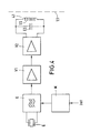
Die Ergänzung der Ausführungsform nach Fig. 2 und 3 besteht darin, daß in der Ein-Auslesevorrichtung dem Oszillator G ein Modulator M vorgeschaltet ist, dem über einen Eingang "Inf" die zusätzlichen Daten zugeführt werden, die vom Modulator M als Frequenzmodulation dem Ausgangssignal des Oszillators G aufgeprägt werden. In Fig. 4 ist im Unterschied zu Fig. 2 die Empfangsseite nicht dargestellt. Die Schaltungsteile auf der Empfangsseite sind Fig. 5 zu entnehmen. Wie man leicht erkennt, ist an den Schwingkreis LE-CE ein Demodulator DM angeschlossen, der seine Speisespannung von der Gleichspannungsseite des Gleichrichters D her erhält und dessen Ausgang mit einem weiteren Eingang des Mikrocomputers CP verbunden ist.The addition of the embodiment of FIGS. 2 and 3 is that in the read-in device, the oscillator G is preceded by a modulator M, to which the additional data are supplied via an input "Inf", which the modulator M uses as frequency modulation to output the output signal of the Oscillator G are impressed. In contrast to FIG. 2, the receiving side is not shown in FIG. 4. The circuit parts on the receiving side can be seen in FIG. 5. As can easily be seen, a demodulator DM is connected to the resonant circuit LE-CE, which receives its supply voltage from the DC voltage side of the rectifier D and whose output is connected to a further input of the microcomputer CP.
Die dem Hochfrequenzsignal in Form der Frequenzmodulation aufgeprägten Daten werden im Demodulator DM wiedergewonnen und dem Mikrocomputer CP zur Verarbeitung zugeführt.The data impressed on the high-frequency signal in the form of frequency modulation are recovered in the demodulator DM and fed to the microcomputer CP for processing.
Im dargestellten Ausführungsbeispiel erfolgt der auf induktivem Wege übertragene Datenverkehr nur einseitig, während der auf optischem Wege übertragene Datenverkehr zweiseitig verläuft. Es ist grundsätzlich auch möglich, den auf induktivem Wege übertragenen Datenverkehr zweiseitig auszugestalten. Hierzu müssen in nicht eigens dargestellter Weise lediglich sowohl im Sendekopf 3 als auch im Abtastkopf 4 zwei Spulen vorgesehen sein, die jeweils Teil eines Schwingkreises sind. Es sind dann jeweils zwei Paare von Schwingkreisen vorhanden, die auf unterschiedlichen Frequenzen arbeiten und von denen eines zur Energieübertragung und das andere zur Datenübertragung dient. Auf diese Weise ist es auch möglich, eine Einrichtung aufzubauen, mit der bei induktiver Energieübertragung von der Ein-Auslesevorrichtung her ein bidirektionaler Datenverkehr sowohl auf optischem als auch auf induktivem Wege möglich ist.In the exemplary embodiment shown, the data traffic transmitted by inductive means takes place only on one side, while the data traffic transmitted by optical means runs on both sides. In principle, it is also possible to configure the data traffic transmitted by inductive means on two sides. For this purpose, two coils, each of which is part of an oscillating circuit, only have to be provided both in the transmitting
Im folgenden wird anhand der Fig. 6 bis 8 ein Ausführungsbeispiel beschrieben, bei dem sowohl die Energieübertragung als auch die Datenübertragung auf rein induktivem Wege erfolgen.An exemplary embodiment is described below with reference to FIGS. 6 to 8, in which both the energy transmission and the data transmission take place in a purely inductive way.
In Fig. 6 sind lediglich die Bauelemente dargestellt, die zum Verständnis dieser Ausführungsform notwendig sind. Ein induktiver Abtastkopf 14 ist bei dieser Ausführungsform in nicht dargestellter Weise, ähnlich wie der optische Abtastkopf 4 der vorbeschriebenen Ausführungsformen, über Verstärker an einen Sender angeschlossen, der ein Hochfrequenzsignal f1 abgibt, dem in Form einer Frequenzmodulation Daten aufgeprägt sind. Dieses Signal wird einer Induktionsspule 14.1 zugeführt, die zusammen mit einem Kondensator C1 Teil eines elektrischen Schwingkreises ist und im Abtastkopf 14 angeordnet ist. Weiterhin enthält der Abtastkopf 14 eine zweite Induktionsspule 14.2, die in nicht dargestellter Weise konzentrisch zur ersten Induktionsspule 14.1 angeordnet ist und zusammen mit einem Kondensator C2 Teil eines zweiten elektrischen Schwingkreises ist, der auf eine Frequenz f2 abgestimmt ist und in nicht dargestellter Weise über Verstärker mit einem Datenempfänger verbunden ist. Dieser Datenempfänger empfängt ein Hochfrequenzsignal mit der Frequenz f2, dem ebenfalls in Form einer Frequenzmodulation Daten aufgeprägt sind. Die beiden Frequenzen f1 und f2 sind unterschiedlich gewählt und können beispielsweise 32 kHz und 50 kHz betragen.In Fig. 6 only the components are shown, which are necessary for understanding this embodiment. In this embodiment, an
Ein in Fig. 6 ebenfalls nicht dargestellter Zähler, der in analoger Weise, wie bei den vorbeschriebenen Ausführungsbeispielen, einen mikroprozessorgesteuerten Datenspeicher aufweist, ist mit einem induktiven Sendekopf 13 verbunden, wobei die Schnittstelle zwischen dem induktiven Abtastkopf 14 und dein induktiven Sendekopf 13 durch räumliche Annäherung von Abtastkopf und Sendekopf zur Erzielung eines magnetischen Signalweges gebildet wird. Hierzu enthält der Sendekopf 13 eine erste Induktionsspule 13.1, die zusammen mit einem Kondensator C3 Teil eines auf die Frequenz f1 abgestimmten Schwingkreises bildet, der an einen Gleichrichter 17 angeschlossen ist, der an seinen Gleichspannungsausgängen ein durch einen Kondensator C5 geglättetes Gleichspannungssignal abgibt, das als Speisespannung (CP-SPEISESP.) dem Datenspeicher zugeführt wird. Weiterhin werden am Gleichrichter 17 die dem von der Induktionsspule 13.1 empfangenen Signal aufgeprägten Daten ausgekoppelt und einem Datenempfänger 15 zugeführt, der seine Speisespannung ebenfalls vom Gleichrichter 17 aus erhält. Der Datenausgang des Datenempfängers 15 ist mit einem Dateneingang (CP-EMPF.DATEN) des Datenspeichers verbunden.A counter (also not shown in FIG. 6), which has a microprocessor-controlled data memory in an analogous manner to the above-described exemplary embodiments, is connected to an
Der Sendekopf 13 enthält eine zweite Induktionsspule 13.2, die zusammen mit einem Kondensator C4 Teil eines elektrischen Schwingkreises ist, der auf die Frequenz f2 abgestimmt ist und mit einem Datensender 16 verbunden ist, der seine Speisespannung vom Gleichrichter 17 aus erhält und dessen Dateneingang mit einem Datenausgang (CP-SENDEDATEN) des Datenspeichers verbunden ist.The
Zum Auslesen von Daten wird der Abtastkopf 14 durch Ansetzen an eine entsprechende Stelle an einem Gehäuse (s. beispielsweise Fig. 1) gegenüber dem Sendekopf 13 so angeordnet, daß die Induktionsspulen 14.1 und 13.1 sowie 14.2 und 13.2 einander gegenüberliegen. Über das Hochfrequenzsignal mit der Frequenz f1 wird elektrische Energie zugeführt zur Erzeugung der Speisespannungen und zur Auslösung des Auslesevorgangs. Hierzu werden die auszulesenden Daten dem Datensender 16 zugeführt und in einer Frequenzmodulation dem Hochfrequenzsignal mit der Frequenz f2 aufgeprägt, das dann über die Induktionsspulen 13.2 und 14.2 auf den Abtastkopf 14 übertragen und den Empfangseinrichtungen zugeführt wird. Sollen Daten in den Datenspeicher eingelesen werden oder Prüfvorgänge ausgelöst werden so dienen hierzu die gegebenenfalls dem Hochfrequenzsignal mit der Frequenz f1 aufgeprägten Daten, die über den Datenempfänger 15 dem Datenspeicher zugeführt werden.To read out data, the
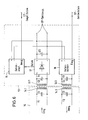
In Fig. 7 ist eine Variante der Ausführungsform nach Fig. 6 dargestellt, bei der das zur Zuführung der elektrischen Energie zur Erzeugung der Speisespannungen zugeführte Hochfrequenzsignal nicht zur Datenübertragung verwendet werden soll. Es wird dann mit drei Arbeitsfrequenzen f1, f2 und f3 gearbeitet. Der induktive Abtastkopf 24 enthält eine erste Induktionsspule 24.1, die zusammen mit dem Kondensator C6 Teil eines Schwingkreises mit der Frequenz f1 ist, eine zweite Induktionsspule 24.2, die zusammen mit dem Kondensator C7 Teil eines Schwingkreises mit der Frequenz f2 ist und eine dritte Induktionsspule 24.3, die mit dem Kondensator C8 Teil eines Schwingkreises mit der Frequenz f3 ist. Die Induktionsspulen 24.1, 24.2 und 24.3 können im Abtastkopf 24 so angeordnet sein wie dies in Fig. 8 dargestellt ist. Hier liegen die drei Induktionsspulen konzentrisch ineinander, wobei die äußerste Induktionsspule 24.1 zur Übertragung der elektrischen Energie dient, die zur Erzeugung der Speisespannung verwendet wird, während die beiden signalübertragenden Induktionsspulen 24.2 und 24.3 innerhalb dieser ersten Induktionsspule konzentrisch angeordnet sind. Über eine Kabelverbindung 28 ist der Abtastkopf 24 mit den bereits erwähnten Sende- und Empfangseinrichtungen verbunden.FIG. 7 shows a variant of the embodiment according to FIG. 6, in which the high-frequency signal supplied for supplying the electrical energy for generating the supply voltages is not to be used for data transmission. It then works with three working frequencies f1, f2 and f3. The
Der Sendekopf 23 enthält eine erste Induktionsspule 23.1, die zusammen mit einem Kondensator C9 einen Schwingkreis mit der Frequenz f1 bildet, eine zweite Induktionsspule 23.2, die zusammen mit dem Kondensator C10 einen Schwingkreis mit der Frequenz f2 bildet und eine dritte Induktionsspule 23.3, die zusammen mit dem Kondensator C11 einen Schwingkreis mit der Frequenz f3 bildet. Die erste Induktionsspule 23.1 ist an einen Gleichrichter 27 angeschlossen, der an seinem Gleichspannungsausgang die durch einen Kondensator C12 geglättete Speisespannung abgibt, die einerseits dem nicht dargestellten Datenspeicher (CP-SPEISESP.) zugeführt wird und andererseits zur Versorgung eines Datensenders 26 und eines Datenempfängers 25 dient. Der Datensender 26 ist an die zweite Induktionsspule 23.2 und der Datenempfänger 25 an die dritte Induktionsspule 23.3 angeschlossen. Der Dateneingang des Datensenders 26 ist mit einem Datenausgang (CP-SENDEDATEN) des Datenspeichers verbunden, während der Datenausgang des Datenempfängers 25 mit einem Dateneingang (CP-EMPF.DATEN) des Datenspeichers verbunden ist.The transmitter head 23 contains a first induction coil 23.1, which together with a capacitor C9 forms an oscillating circuit with the frequency f1, a second induction coil 23.2, which together with the capacitor C10 forms an oscillating circuit with the frequency f2, and a third induction coil 23.3, which together with the capacitor C11 forms an oscillating circuit with the frequency f3. The first induction coil 23.1 is connected to a
Zum Aus- und Einlesen von Daten wird in der bereits mehrfach beschriebenen Weise der Abtastkopf 24 an den Sendekopf 23 angenähert und über die Induktionsspulen 24.1, 24.2, 24.3 und 23.1, 23.2, 23.3 die entsprechenden Signale zu- und abgeführt.In order to read out and read in data, the
Auf diese Weise ist ein Duplex-Datenverkehr bei vollständiger Entkopplung von der Energiezuführung möglich.In this way, duplex data traffic is possible with complete decoupling from the energy supply.
Claims (11)
Applications Claiming Priority (2)
| Application Number | Priority Date | Filing Date | Title |
|---|---|---|---|
| DE4016010A DE4016010A1 (en) | 1990-05-18 | 1990-05-18 | METHOD FOR READING AND / OR READING IN DATA IN A MICROPROCESSOR-CONTROLLED DATA STORAGE, IN PARTICULAR A REGISTERING MEASURING OR COUNTING DEVICE, AND DEVICE FOR CARRYING OUT THE METHOD |
| DE4016010 | 1990-05-18 |
Publications (2)
| Publication Number | Publication Date |
|---|---|
| EP0457306A2 true EP0457306A2 (en) | 1991-11-21 |
| EP0457306A3 EP0457306A3 (en) | 1992-03-18 |
Family
ID=6406705
Family Applications (1)
| Application Number | Title | Priority Date | Filing Date |
|---|---|---|---|
| EP19910107872 Withdrawn EP0457306A3 (en) | 1990-05-18 | 1991-05-15 | Method and device to read and write a data memory driven by a microprocessor, especially for a measuring or counting recording device |
Country Status (2)
| Country | Link |
|---|---|
| EP (1) | EP0457306A3 (en) |
| DE (1) | DE4016010A1 (en) |
Cited By (6)
| Publication number | Priority date | Publication date | Assignee | Title |
|---|---|---|---|---|
| GB2273631A (en) * | 1992-11-25 | 1994-06-22 | Ampy Automation Digilog | Improvements relating to commodity measuring meters |
| WO1995007521A1 (en) * | 1993-09-11 | 1995-03-16 | Renishaw Plc | Signal transmission system for probes |
| EP0780822A1 (en) * | 1995-12-20 | 1997-06-25 | Philips Patentverwaltung GmbH | Method and device for contactless transmission of measured values |
| EP0825577A1 (en) * | 1996-08-12 | 1998-02-25 | Laserline SpA | System for the remote recognition and reading of meters |
| FR2841066A1 (en) * | 2002-06-14 | 2003-12-19 | Michaud Sa | Portable terminal water/electricity meter reading information transmission system having first system resonant circuit second resonant circuit interfacing with reversible magnetic control switch first resonant circuit commanded. |
| EP3227648A1 (en) * | 2014-12-04 | 2017-10-11 | GWF MessSysteme AG | Meter and method for determining meter readings and method for the wireless transmission of electrical energy |
Families Citing this family (2)
| Publication number | Priority date | Publication date | Assignee | Title |
|---|---|---|---|---|
| DE4322811A1 (en) * | 1992-07-08 | 1994-02-10 | Duerrwaechter E Dr Doduco | Low-current signal transmission system esp. on vehicular wiring |
| DE10255741A1 (en) * | 2002-11-28 | 2004-06-09 | Endress + Hauser Conducta Gesellschaft für Mess- und Regeltechnik mbH + Co. KG | Modular transmitter with galvanically isolated sensor |
Citations (3)
| Publication number | Priority date | Publication date | Assignee | Title |
|---|---|---|---|---|
| GB2138609A (en) * | 1983-04-19 | 1984-10-24 | Emi Ltd | Electronic counter for mechanical drive |
| DE3613150A1 (en) * | 1986-04-18 | 1987-10-22 | Krupp Gmbh | Device for contactless data transmission |
| DE3804592C1 (en) * | 1988-02-13 | 1989-08-03 | Spanner-Pollux Gmbh, 6700 Ludwigshafen, De | Remote read-out system for consumption meter (electricity meter, supply meter) |
-
1990
- 1990-05-18 DE DE4016010A patent/DE4016010A1/en not_active Withdrawn
-
1991
- 1991-05-15 EP EP19910107872 patent/EP0457306A3/en not_active Withdrawn
Patent Citations (3)
| Publication number | Priority date | Publication date | Assignee | Title |
|---|---|---|---|---|
| GB2138609A (en) * | 1983-04-19 | 1984-10-24 | Emi Ltd | Electronic counter for mechanical drive |
| DE3613150A1 (en) * | 1986-04-18 | 1987-10-22 | Krupp Gmbh | Device for contactless data transmission |
| DE3804592C1 (en) * | 1988-02-13 | 1989-08-03 | Spanner-Pollux Gmbh, 6700 Ludwigshafen, De | Remote read-out system for consumption meter (electricity meter, supply meter) |
Cited By (7)
| Publication number | Priority date | Publication date | Assignee | Title |
|---|---|---|---|---|
| GB2273631A (en) * | 1992-11-25 | 1994-06-22 | Ampy Automation Digilog | Improvements relating to commodity measuring meters |
| WO1995007521A1 (en) * | 1993-09-11 | 1995-03-16 | Renishaw Plc | Signal transmission system for probes |
| EP0780822A1 (en) * | 1995-12-20 | 1997-06-25 | Philips Patentverwaltung GmbH | Method and device for contactless transmission of measured values |
| US5859873A (en) * | 1995-12-20 | 1999-01-12 | U.S. Philips Corporation | Method and arrangement for non-contact transmission of measured values |
| EP0825577A1 (en) * | 1996-08-12 | 1998-02-25 | Laserline SpA | System for the remote recognition and reading of meters |
| FR2841066A1 (en) * | 2002-06-14 | 2003-12-19 | Michaud Sa | Portable terminal water/electricity meter reading information transmission system having first system resonant circuit second resonant circuit interfacing with reversible magnetic control switch first resonant circuit commanded. |
| EP3227648A1 (en) * | 2014-12-04 | 2017-10-11 | GWF MessSysteme AG | Meter and method for determining meter readings and method for the wireless transmission of electrical energy |
Also Published As
| Publication number | Publication date |
|---|---|
| DE4016010A1 (en) | 1991-11-21 |
| EP0457306A3 (en) | 1992-03-18 |
Similar Documents
| Publication | Publication Date | Title |
|---|---|---|
| DE4021258C2 (en) | Field sensor communication system | |
| DE3633939C2 (en) | ||
| EP0980603B1 (en) | Plug-and-socket connection | |
| EP0583690B1 (en) | Chip card with field intensity detector | |
| DE4002801C1 (en) | ||
| DE3934007A1 (en) | TWO WIRE REMOTE EQUIPMENT | |
| EP0165386A1 (en) | Method and storage system for the storage of control data for press actuators | |
| DE2905734A1 (en) | ELECTROOPTIC DATA TRANSMISSION DEVICE | |
| DE2701184A1 (en) | CIRCUIT ARRANGEMENT FOR TRANSMISSION OF MEASURED VALUE SIGNALS | |
| DE4344071A1 (en) | Energy and/or data transmission device | |
| EP1573664B1 (en) | Device for determining the energy level of an energy store of a mobile data carrier | |
| DE3632840C2 (en) | ||
| EP0457306A2 (en) | Method and device to read and write a data memory driven by a microprocessor, especially for a measuring or counting recording device | |
| DE19923634A1 (en) | Sending and receiving device | |
| DE2439416A1 (en) | DEVICE FOR MONITORING THE OPERATING CONDITIONS OF MACHINE PARTS | |
| DE102004032130B4 (en) | Frequency synthesizer and method for operating a frequency synthesizer | |
| DE3637689C1 (en) | Fiber optic data acquisition and transmission device | |
| EP0229247A2 (en) | Contactless signalling device | |
| EP2508839B1 (en) | Measuring device with transmission circuit for wireless transmission of a measurement value transmission signal | |
| DE1813319B2 (en) | Identification system providing "key" - employs radiation transmitter in fixed appts and responder cct in key | |
| DE4038970A1 (en) | METHOD AND DEVICE FOR BIDIRECTIONAL DATA TRANSMISSION BETWEEN A TEXTILE MACHINE AND A TEXTILE PRODUCT | |
| DE4214083A1 (en) | ELECTRONIC DEVICE FOR CHECKING THE CONDITION OF POWER SUPPLIES | |
| DE69827908T2 (en) | TRANSPONDER FOR TOUCHLESS INDUCTIVE COMMUNICATION | |
| EP0582257A2 (en) | Method and device for transmitting shift signal information | |
| DE60102713T2 (en) | LASER MEASURING DEVICE OF A HIGH-FREQUENCY MAGNETIC FIELD WITH CONSTANT AMPLITUDE AND FREQUENCY |
Legal Events
| Date | Code | Title | Description |
|---|---|---|---|
| PUAI | Public reference made under article 153(3) epc to a published international application that has entered the european phase |
Free format text: ORIGINAL CODE: 0009012 |
|
| AK | Designated contracting states |
Kind code of ref document: A2 Designated state(s): AT BE CH DE DK ES FR GB GR IT LI LU NL SE |
|
| PUAL | Search report despatched |
Free format text: ORIGINAL CODE: 0009013 |
|
| AK | Designated contracting states |
Kind code of ref document: A3 Designated state(s): AT BE CH DE DK ES FR GB GR IT LI LU NL SE |
|
| STAA | Information on the status of an ep patent application or granted ep patent |
Free format text: STATUS: THE APPLICATION IS DEEMED TO BE WITHDRAWN |
|
| 18D | Application deemed to be withdrawn |
Effective date: 19920919 |