EP0455738B2 - Codeur, decodeur et codeur/decodeur par transformees a faible debit binaire pour applications audio de haute qualite - Google Patents
Codeur, decodeur et codeur/decodeur par transformees a faible debit binaire pour applications audio de haute qualite Download PDFInfo
- Publication number
- EP0455738B2 EP0455738B2 EP90903518A EP90903518A EP0455738B2 EP 0455738 B2 EP0455738 B2 EP 0455738B2 EP 90903518 A EP90903518 A EP 90903518A EP 90903518 A EP90903518 A EP 90903518A EP 0455738 B2 EP0455738 B2 EP 0455738B2
- Authority
- EP
- European Patent Office
- Prior art keywords
- subband
- blocks
- transform
- window
- time
- Prior art date
- Legal status (The legal status is an assumption and is not a legal conclusion. Google has not performed a legal analysis and makes no representation as to the accuracy of the status listed.)
- Expired - Lifetime
Links
- 238000000034 method Methods 0.000 claims description 113
- 238000004458 analytical method Methods 0.000 claims description 51
- 238000003786 synthesis reaction Methods 0.000 claims description 50
- 230000015572 biosynthetic process Effects 0.000 claims description 38
- 230000004044 response Effects 0.000 claims description 33
- 230000000694 effects Effects 0.000 claims description 27
- 230000005540 biological transmission Effects 0.000 claims description 25
- 238000012545 processing Methods 0.000 claims description 21
- 238000005070 sampling Methods 0.000 claims description 17
- 230000005236 sound signal Effects 0.000 claims description 10
- 230000003044 adaptive effect Effects 0.000 abstract description 33
- 230000003595 spectral effect Effects 0.000 abstract description 30
- 238000013139 quantization Methods 0.000 abstract description 15
- 239000000523 sample Substances 0.000 description 100
- 230000008569 process Effects 0.000 description 55
- 230000000873 masking effect Effects 0.000 description 40
- 230000006870 function Effects 0.000 description 26
- 238000012937 correction Methods 0.000 description 19
- 238000013461 design Methods 0.000 description 19
- 230000007704 transition Effects 0.000 description 17
- 238000001228 spectrum Methods 0.000 description 11
- 238000004422 calculation algorithm Methods 0.000 description 10
- 230000002829 reductive effect Effects 0.000 description 8
- 230000003068 static effect Effects 0.000 description 8
- 238000004364 calculation method Methods 0.000 description 7
- 238000004891 communication Methods 0.000 description 7
- 230000014509 gene expression Effects 0.000 description 7
- 230000001174 ascending effect Effects 0.000 description 5
- 239000002131 composite material Substances 0.000 description 5
- 238000010586 diagram Methods 0.000 description 5
- 239000000872 buffer Substances 0.000 description 4
- 230000008859 change Effects 0.000 description 4
- 230000000737 periodic effect Effects 0.000 description 4
- 230000009467 reduction Effects 0.000 description 4
- 238000013459 approach Methods 0.000 description 3
- OVOUKWFJRHALDD-UHFFFAOYSA-N 2-[2-(2-acetyloxyethoxy)ethoxy]ethyl acetate Chemical compound CC(=O)OCCOCCOCCOC(C)=O OVOUKWFJRHALDD-UHFFFAOYSA-N 0.000 description 2
- IXKSXJFAGXLQOQ-XISFHERQSA-N WHWLQLKPGQPMY Chemical compound C([C@@H](C(=O)N[C@@H](CC=1C2=CC=CC=C2NC=1)C(=O)N[C@@H](CC(C)C)C(=O)N[C@@H](CCC(N)=O)C(=O)N[C@@H](CC(C)C)C(=O)N1CCC[C@H]1C(=O)NCC(=O)N[C@@H](CCC(N)=O)C(=O)N[C@@H](CC(O)=O)C(=O)N1CCC[C@H]1C(=O)N[C@@H](CCSC)C(=O)N[C@@H](CC=1C=CC(O)=CC=1)C(O)=O)NC(=O)[C@@H](N)CC=1C2=CC=CC=C2NC=1)C1=CNC=N1 IXKSXJFAGXLQOQ-XISFHERQSA-N 0.000 description 2
- 230000002411 adverse Effects 0.000 description 2
- 230000015556 catabolic process Effects 0.000 description 2
- 238000005094 computer simulation Methods 0.000 description 2
- 238000006731 degradation reaction Methods 0.000 description 2
- 238000001514 detection method Methods 0.000 description 2
- 230000036039 immunity Effects 0.000 description 2
- 230000008054 signal transmission Effects 0.000 description 2
- 230000009466 transformation Effects 0.000 description 2
- 101100119355 Arabidopsis thaliana EXPA23 gene Proteins 0.000 description 1
- 101150099000 EXPA1 gene Proteins 0.000 description 1
- 101150098426 EXPA10 gene Proteins 0.000 description 1
- 101150078847 EXPA11 gene Proteins 0.000 description 1
- 101150017205 EXPA12 gene Proteins 0.000 description 1
- 101150075679 EXPA13 gene Proteins 0.000 description 1
- 101150026593 EXPA14 gene Proteins 0.000 description 1
- 101150085145 EXPA15 gene Proteins 0.000 description 1
- 101150005608 EXPA16 gene Proteins 0.000 description 1
- 101150064360 EXPA17 gene Proteins 0.000 description 1
- 101150000117 EXPA18 gene Proteins 0.000 description 1
- 101150012241 EXPA20 gene Proteins 0.000 description 1
- 101150070705 EXPA21 gene Proteins 0.000 description 1
- 101150051170 EXPA22 gene Proteins 0.000 description 1
- 101150047524 EXPA24 gene Proteins 0.000 description 1
- 101150117371 EXPA25 gene Proteins 0.000 description 1
- 101150057084 EXPA26 gene Proteins 0.000 description 1
- 101150093545 EXPA3 gene Proteins 0.000 description 1
- 101150028048 EXPA5 gene Proteins 0.000 description 1
- 101150022731 EXPA7 gene Proteins 0.000 description 1
- 101150079841 EXPA8 gene Proteins 0.000 description 1
- 101150017513 EXPA9 gene Proteins 0.000 description 1
- 102100029095 Exportin-1 Human genes 0.000 description 1
- 102100029091 Exportin-2 Human genes 0.000 description 1
- 101710147878 Exportin-2 Proteins 0.000 description 1
- 102100032833 Exportin-4 Human genes 0.000 description 1
- 101710147879 Exportin-4 Proteins 0.000 description 1
- 102100032839 Exportin-5 Human genes 0.000 description 1
- 108700037230 Exportin-5 Proteins 0.000 description 1
- 102100032837 Exportin-6 Human genes 0.000 description 1
- 101710147891 Exportin-6 Proteins 0.000 description 1
- 102100033139 Exportin-7 Human genes 0.000 description 1
- 108700037767 Exportin-7 Proteins 0.000 description 1
- 101000583839 Homo sapiens Muscleblind-like protein 1 Proteins 0.000 description 1
- 102100030965 Muscleblind-like protein 1 Human genes 0.000 description 1
- 101100119346 Oryza sativa subsp. japonica EXPA19 gene Proteins 0.000 description 1
- 101100502008 Oryza sativa subsp. japonica EXPA27 gene Proteins 0.000 description 1
- 101100502009 Oryza sativa subsp. japonica EXPA28 gene Proteins 0.000 description 1
- 101100502010 Oryza sativa subsp. japonica EXPA29 gene Proteins 0.000 description 1
- 101100502011 Oryza sativa subsp. japonica EXPA30 gene Proteins 0.000 description 1
- 101100502012 Oryza sativa subsp. japonica EXPA31 gene Proteins 0.000 description 1
- 101100502013 Oryza sativa subsp. japonica EXPA32 gene Proteins 0.000 description 1
- 101100502014 Oryza sativa subsp. japonica EXPA33 gene Proteins 0.000 description 1
- 101100119348 Saccharomyces cerevisiae (strain ATCC 204508 / S288c) EXP1 gene Proteins 0.000 description 1
- 101100275845 Streptococcus pneumoniae (strain ATCC BAA-255 / R6) cshA gene Proteins 0.000 description 1
- 101100269618 Streptococcus pneumoniae serotype 4 (strain ATCC BAA-334 / TIGR4) aliA gene Proteins 0.000 description 1
- 101100439746 Streptococcus pneumoniae serotype 4 (strain ATCC BAA-334 / TIGR4) cinA gene Proteins 0.000 description 1
- 101100354192 Streptococcus pneumoniae serotype 4 (strain ATCC BAA-334 / TIGR4) exp5 gene Proteins 0.000 description 1
- 101100502015 Streptococcus pneumoniae serotype 4 (strain ATCC BAA-334 / TIGR4) exp7 gene Proteins 0.000 description 1
- 101100502016 Streptococcus pneumoniae serotype 4 (strain ATCC BAA-334 / TIGR4) exp8 gene Proteins 0.000 description 1
- 239000008186 active pharmaceutical agent Substances 0.000 description 1
- 238000007792 addition Methods 0.000 description 1
- 238000003491 array Methods 0.000 description 1
- 230000008901 benefit Effects 0.000 description 1
- 230000003139 buffering effect Effects 0.000 description 1
- 230000000295 complement effect Effects 0.000 description 1
- 238000010276 construction Methods 0.000 description 1
- 230000003247 decreasing effect Effects 0.000 description 1
- 230000001934 delay Effects 0.000 description 1
- 238000011156 evaluation Methods 0.000 description 1
- 230000005713 exacerbation Effects 0.000 description 1
- 230000007717 exclusion Effects 0.000 description 1
- 108700002148 exportin 1 Proteins 0.000 description 1
- 239000000284 extract Substances 0.000 description 1
- 238000001914 filtration Methods 0.000 description 1
- 230000003993 interaction Effects 0.000 description 1
- 230000007246 mechanism Effects 0.000 description 1
- 238000002156 mixing Methods 0.000 description 1
- 239000000203 mixture Substances 0.000 description 1
- 238000012544 monitoring process Methods 0.000 description 1
- 101150109310 msrAB1 gene Proteins 0.000 description 1
- 230000007935 neutral effect Effects 0.000 description 1
- 238000010606 normalization Methods 0.000 description 1
- 230000003287 optical effect Effects 0.000 description 1
- 230000008447 perception Effects 0.000 description 1
- 230000010363 phase shift Effects 0.000 description 1
- 230000000644 propagated effect Effects 0.000 description 1
- 239000012723 sample buffer Substances 0.000 description 1
- 230000035945 sensitivity Effects 0.000 description 1
- 238000000926 separation method Methods 0.000 description 1
Images


Classifications
-
- G—PHYSICS
- G10—MUSICAL INSTRUMENTS; ACOUSTICS
- G10L—SPEECH ANALYSIS TECHNIQUES OR SPEECH SYNTHESIS; SPEECH RECOGNITION; SPEECH OR VOICE PROCESSING TECHNIQUES; SPEECH OR AUDIO CODING OR DECODING
- G10L19/00—Speech or audio signals analysis-synthesis techniques for redundancy reduction, e.g. in vocoders; Coding or decoding of speech or audio signals, using source filter models or psychoacoustic analysis
- G10L19/02—Speech or audio signals analysis-synthesis techniques for redundancy reduction, e.g. in vocoders; Coding or decoding of speech or audio signals, using source filter models or psychoacoustic analysis using spectral analysis, e.g. transform vocoders or subband vocoders
- G10L19/0212—Speech or audio signals analysis-synthesis techniques for redundancy reduction, e.g. in vocoders; Coding or decoding of speech or audio signals, using source filter models or psychoacoustic analysis using spectral analysis, e.g. transform vocoders or subband vocoders using orthogonal transformation
-
- G—PHYSICS
- G06—COMPUTING; CALCULATING OR COUNTING
- G06T—IMAGE DATA PROCESSING OR GENERATION, IN GENERAL
- G06T9/00—Image coding
- G06T9/005—Statistical coding, e.g. Huffman, run length coding
-
- G—PHYSICS
- G11—INFORMATION STORAGE
- G11B—INFORMATION STORAGE BASED ON RELATIVE MOVEMENT BETWEEN RECORD CARRIER AND TRANSDUCER
- G11B20/00—Signal processing not specific to the method of recording or reproducing; Circuits therefor
- G11B20/10—Digital recording or reproducing
- G11B20/10527—Audio or video recording; Data buffering arrangements
-
- G—PHYSICS
- G11—INFORMATION STORAGE
- G11B—INFORMATION STORAGE BASED ON RELATIVE MOVEMENT BETWEEN RECORD CARRIER AND TRANSDUCER
- G11B20/00—Signal processing not specific to the method of recording or reproducing; Circuits therefor
- G11B20/10—Digital recording or reproducing
- G11B20/18—Error detection or correction; Testing, e.g. of drop-outs
- G11B20/1806—Pulse code modulation systems for audio signals
- G11B20/1809—Pulse code modulation systems for audio signals by interleaving
-
- H—ELECTRICITY
- H03—ELECTRONIC CIRCUITRY
- H03M—CODING; DECODING; CODE CONVERSION IN GENERAL
- H03M5/00—Conversion of the form of the representation of individual digits
- H03M5/02—Conversion to or from representation by pulses
- H03M5/04—Conversion to or from representation by pulses the pulses having two levels
-
- H—ELECTRICITY
- H04—ELECTRIC COMMUNICATION TECHNIQUE
- H04B—TRANSMISSION
- H04B1/00—Details of transmission systems, not covered by a single one of groups H04B3/00 - H04B13/00; Details of transmission systems not characterised by the medium used for transmission
- H04B1/66—Details of transmission systems, not covered by a single one of groups H04B3/00 - H04B13/00; Details of transmission systems not characterised by the medium used for transmission for reducing bandwidth of signals; for improving efficiency of transmission
- H04B1/665—Details of transmission systems, not covered by a single one of groups H04B3/00 - H04B13/00; Details of transmission systems not characterised by the medium used for transmission for reducing bandwidth of signals; for improving efficiency of transmission using psychoacoustic properties of the ear, e.g. masking effect
Definitions
- the invention relates in general to high-quality low bit-rate digital signal processing of audio signals such as music.
- Subband coding may be implemented by a bank of digital bandpass filters.
- Transform coding may be implemented by any of several time-domain to frequency-domain transforms which simulate a bank of digital bandpass filters. Although transforms are easier to implement and require less computational power and hardware than digital filters, they have less design flexibility in the sense that each bandpass filter "frequency bin" represented by a transform coefficient has a uniform bandwidth. By contrast, a bank of digital bandpass filters can be designed to have different subband bandwidths. Transform coefficients can, however, be grouped together to define "subbands" having bandwidths which are multiples of a single transform coefficient bandwidth.
- the term "subband” is used hereinafter to refer to selected portions of the total signal bandwidth, whether implemented by a subband coder or a transform coder.
- a subband as implemented by transform coder is defined by a set of one or more adjacent transform coefficients or frequency bins. The bandwidth of a transform coder frequency bin depends upon the coder's sampling rate and the number of samples in each signal sample block (the
- the first is the bandwidth of the regions between the filter passband and stopbands (the transition bands).
- the second is the attenuation level in the stopbands.
- the measure of filter "selectivity” is the steepness of the filter response curve within the transition bands (steepness of transition band rolloff), and the level of attenuation in the stopbands (depth of stopband rejection).
- the human ear displays frequency-analysis properties resembling those of highly asymmetrical tuned filters having variable center frequencies.
- the frequency-resolving power of the human ear's tuned filters varies with frequency throughout the audio spectrum.
- the ear can discern signals closer together in frequency at frequencies below about 500 Hz, but widening as the frequency progresses upward to the limits of audibility.
- the effective bandwidth of such an auditory filter is referred to as a critical band.
- An important quality of the critical band is that psychoacoustic-masking effects are most strongly manifested within a critical band--a dominant signal within a critical band can suppress the audibility of other signals anywhere within that critical band. Signals at frequencies outside that critical band are not masked as strongly. See generally, the Audio Engineering Handbook, K. Blair Benson ed., McGraw-Hill, San Francisco, 1988, pages 1.40-1.42 and 4.8-4.10.
- the subband bandwidth is about half or less than half of the critical band (and if the transition band rolloff is sufficiently steep and the stopband rejection is sufficiently deep), the most effective masking of the undesired distortion products is likely to occur even for signals whose frequency is near the edge of the subband passband bandwidth. If the subband bandwidth is more than half a critical band, there is the possibility that the dominant signal will cause the ear's critical band to be offset from the coder's subband so that some of the undesired distortion products outside the ear's critical bandwidth are not masked. These effects are most objectionable at low frequencies where the ear's critical band is narrower.
- the document WO 88/01811 discloses a digital coding process for transmitting and/or storing acoustic signals, in particular musical signals, in which a block of N pick-up values of the acoustic signal is transformed into a block of M spectral coefficients using a Discrete Cosine Transform, a TDAC Transform or a Fast Fourier Transform.
- the process chooses an initial quantizer step-size, applies entropy coding, and reiterates quantization with different step-sizes until the M spectral coefficients can be coded with a predetermined number of bits. Unused bits are available for allocation in subsequent blocks.
- the spectral coefficients of each block are divided into frequency groups, these frequency groups being selected such that, according to psycho-acoustic masking, noise is not perceivable if the signal energy within each individual frequency group is substantially higher than the noise energy within the same group.
- the coefficients are reconstructed and the signal energy within each frequency group of the reconstructed values is compared with a respective minimum reference value. If the signal energy within one or more of the frequency groups is below the respective reference value, the spectral coefficients are multiplied by a predetermined factor and quantization and coding is performed again in a reiterative manner. The number of reiterations in the inner and the outer iteration loop have to be transmitted as side information.
- Transform coding performance depends upon several factors, including the signal sample block length, transform coding errors, and aliasing cancellation.
- transform encoder and decoder performance is adversely affected not only by the consequential widening of the frequency bins, but also by degradation of the response character istics of the bandpass filter frequency bins: (1) decreased rate of transition band rolloff, and (2) reduced level of stopband rejection.
- This degradation in filter performance results in the undesired creation of or contribution to transform coefficients in nearby frequency bins in response to a desired signal. These undesired contributions are called sidelobe leakage.
- a short block length may result in a nominal filter bandwidth exceeding the ear's critical bandwidth at some or all frequencies, particularly low frequencies. Even if the nominal subband bandwidth is narrower than the ear's critical bandwidth, degraded filter characteristics manifested as a broad transition band and/or poor stopband rejection may result in significant signal components outside the ear's critical bandwidth. In such cases, greater constraints are ordinarily placed on other aspects of the system, particularly quantization accuracy.
- Discrete transforms do not produce a perfectly accurate set of frequency coefficients because they work with only a finite segment of the signal. Strictly speaking, discrete transforms produce a time-frequency representation of the input time-domain signal rather than a true frequency-domain representation which would require infinite transform lengths. For convenience of discussion here, however, the output of discrete transforms will be referred to as a frequency-domain representation.
- the discrete transform assumes the sampled signal only has frequency components whose periods are a submultiple of the finite sample interval. This is equivalent to an assumption that the finite-length signal is periodic. The assumption in general is not true. The assumed periodicity creates discontinuities at the edges of the finite time interval which cause the transform to create phantom high-frequency components.
- One technique which minimizes this effect is to reduce the discontinuity prior to the transformation by weighting the signal samples such that samples near the edges of the interval are close to zero. Samples at the center of the interval are generally passed unchanged, i.e., weighted by a factor of one.
- This weighting function is called an "analysis window" and may be of any shape, but certain windows contribute more favorably to subband filter performance.
- analysis window refers merely to the windowing function performed prior to application of the forward transform.
- design of an analysis window used in the invention is constrained by synthesis window design considerations. Therefore, design and performance properties of an "analysis window” as that term is commonly used in the art may differ from such analysis windows as implemented in this invention.
- the analysis window is a time-domain function. If no other compensation is provided, the recovered or "synthesized" signal will be distorted according to the shape of the analysis window. There are several compensation methods. For example:
- the Nyquist theorem holds that a signal may be accurately recovered from discrete samples when the interval between samples is no larger than one-half the period of the signal's highest frequency component.
- higher-frequency components are misrepresented as lower-frequency components.
- the lower-frequency component is an "alias" for the true component.
- Subband filters and finite digital transforms are not perfect passband filters.
- the transition between the passband and stopband is not infinitely sharp, and the attenuation of signals in the stopband is not infinitely great.
- a passband-filtered input signal is sampled at the Nyquist rate suggested by the passband cut-off frequency, frequencies in the transition band above the cutoff frequency will not be faithfully represented.
- Another object of the invention is to provide improved psychoacoustic-masking techniques in a transform coder processing music signals.
- An encoder provides for the digital encoding of wideband audio information.
- the wideband audio signals are sampled and quantized into time-domain sample blocks. Each sample block is then modulated by an analysis window. Frequency-domain spectral components are then generated in response to the analysis-window weighted time-domain sample block.
- a transform coder having adaptive bit allocation nonuniformly quantizes each transform coefficient, and those coefficients are assembled into a digital output having a format suitable for storage or transmission. Error correction codes may be used in applications where the transmitted signal is subject to noise or other corrupting effects of the communication path.
- a decoder provides for the high-quality reproduction of digitally encoded wideband audio signals encoded by an encoder according to the present invention.
- a decoder receives the digital output of an encoder via a storage device or transmission path. It derives the nonuniformly coded spectral components from the formatted digital signal and reconstructs the frequency-domain spectral components therefrom.
- Time-domain signal sample blocks are generated in response to frequency-domain spectral components by means having characteristics inverse to those of the means in the encoder which generated the frequency-domain spectral components.
- the sample blocks are modulated by a synthesis window.
- the synthesis window has characteristics such that the product of the synthesis-window response and the response of the analysis-window in the encoder produces a composite response which sums to unity for two adjacent overlapped sample blocks. Adjacent sample blocks are overlapped and added to cancel the weighting effects of the analysis and synthesis windows and recover a digitized representation of the time-domain signal which is then converted to a high-quality analog output.
- An encoder/decoder system provides for the digital encoding and high-quality reproduction of wideband audio information.
- the analog wideband audio signals are sampled and quantized into time-domain sample blocks. Each sample block is then modulated by an analysis window. Frequency-domain spectral components are then generated in response to the analysis-window weighted time-domain sample block.
- Nonuniform spectral coding including adaptive bit allocation, quantizes each spectral component, and those components are assembled into a digital format suitable for storage or transmission over communication paths susceptible to signal corrupting noise.
- the decoder portion of the system receives the digital output of the encoder via a storage device or transmission path.
- Time-domain signal sample blocks are generated in response to frequency-domain transform coefficients by means having characteristics inverse to those of the means in the encoder which generated the frequency-domain transform coefficients.
- the sample blocks are modulated by a synthesis window.
- the synthesis window has characteristics such that the product of the synthesis-window response and the response of the analysis-window in the encoder produces a composite response which sums to unity for two adjacent overlapped sample blocks. Adjacent sample blocks are overlapped and added to cancel the weighting effects of the analysis and synthesis windows and recover a digitized representation of the time-domain signal which is then converted to a high-quality analog output.
- a discrete transform generates frequency-domain spectral components in response to the analysis-window weighted time-domain sample blocks.
- the discrete transform has a function equivalent to the alternate application of a modified Discrete Cosine Transform (DCT) and a modified Discrete Sine Transform (DST).
- DCT Discrete Cosine Transform
- DST Discrete Sine Transform
- the discrete transform is implemented by a single modified Discrete Cosine Transform (DCT), however, virtually any time-domain to frequency-domain transform can be used.
- a single FFT is utilized to simultaneously calculate the forward transform for two adjacent signal sample blocks in a single-channel system, or one signal sample block from each channel of a two-channel system.
- a single FFT is utilized to simultaneously calculate the inverse transform for two transform blocks.
- the sampling rate is 44.1 kHz. While the sampling rate is not critical, 44.1 kHz is a suitable sampling rate and it is convenient because it is also the sampling rate used for Compact Discs.
- An alternative embodiment employs a 48 kHz sampling rate.
- the nominal frequency response extends to 15 kHz and the time-domain sample blocks have a length of 512 samples.
- music coding at subjective quality levels suitable for professional broadcasting applications may be achieved using serial bit rates as low as 128 kBits persecond (including overhead information such as error correction codes). Other bit rates yielding varying levels of signal quality may be used.
- the nonuniform transform coder computes a variable bit-length code word for each transform coefficient, which code-word bit length is the sum of a fixed number of bits and a variable number of bits determined by adaptive bit allocation based on whether, because of current signal content, noise in the subband is less subject to psychoacoustic masking than noise in other subbands.
- the fixed number of bits are assigned to each subband based on empirical observations regarding psychoacoustic-masking effects of a single-tone signal in the subband under consideration. The assignment of fixed bits takes into consideration the poorer subjective performance of the system at low frequencies due to the greater selectivity of the ear at low frequencies.
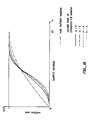
- the empirical technique for allocating bits may be better understood by reference to Figure 13 which shows critical band spectra of the output noise and distortion (e.g., the noise and distortion shown is with respect to auditory critical bands) resulting from a 500 Hz tone (sine wave) for three different bit allocations compared to auditory masking.
- the Figure is intended to demonstrate an empirical approach rather than any particular data.
- Allocation A (the solid line) is a reference, showing the noise and distortion products produced by the 500 Hz sine wave when an arbitrary number of bits are allocated to each of the transform coefficients.
- Allocation B (the short dashed line) shows the noise and distortion products for the same relative bit allocation as allocation A but with 2 fewer bits per transform coefficient.
- Allocation C (the long dashed line) is the same as allocation A for frequencies in the lower part of the audio band up to about 1500 Hz. Allocation C is then the same as allocation B for frequencies in the upper part of the audio band above about 1500 Hz.
- the dotted line shows the auditory masking curve for a 500 Hz tone.
- audible noise is present at frequencies below the 500 Hz tone for all three cases of bit allocation due to the rapid fall off of the masking curve: the noise and distortion product curves are above the masking threshold from about 100 Hz to 300 or 400 Hz.
- the removal of two bits (allocation A to allocation B) exacerbates the audible noise and distortion; adding back the two bits over a portion of the spectrum including the region below the tone, as shown in allocation C, restores the original audible noise and distortion levels.
- Audible noise is also present at high frequencies, but does not change as substantially when bits are removed and added because at that extreme portion of the audio spectrum the noise and distortion products created by the 500 Hz tone are relatively low.
- bit lengths for the various transform coefficients can be allocated that result in acceptable levels of noise and distortion with respect to auditory masking throughout the audio spectrum.
- additional bits could be added to the reference allocation for the transform coefficient containing the 500 Hz tone and nearby coefficients until the noise and distortion dropped below the masking threshold. Similar steps would be taken for other tones throughout the audio spectrum until the overall transform-coefficient bit-length allocation resulted in acceptably low audible noise in the presence of tones, taken one at a time, throughout the audio spectrum.
- the nonuniformly quantized transform coefficients are expressed by a block-floating-point representation comprised of block exponents and variable-length code words.
- the variable-length code words are further comprised of a fixed bit-length portion and a variable length portion of adaptively assigned bits.
- the encoded signal for a pair of transform blocks is assembled into frames composed of exponents and the fixed-length portion of the code words followed by a string of all adaptively allocated bits.
- the exponents and fixed-length portion of code words are assembled separately from adaptively allocated bits to reduce vulnerability to noise burst errors.
- an encoder according to the present invention need not transmit side information regarding the assignment of adaptively allocated bits in each frame.
- the decoder can deduce the correct assignment by applying the same allocation algorithm to the exponents as that used by the encoder.
- an encoder appends the formatted data to frame synchronization bits.
- the formatted data bits are first randomized to reduce the probability of long sequences of bits with values of all ones or zeroes. This is necessary in many environments such as T-1 carrier which will not tolerate such sequences beyond specified lengths. In asynchronous applications, randomization also reduces the probability that valid data within the frame will be mistaken for the block synchronization sequence.
- the formatted data bits are recovered by removing the frame synchronization bits and applying an inverse randomization process.
- error correction codes are utilized to protect the most critical information, that is, the exponents and possibly the fixed portions of the lowest-frequency coefficient code words. Error codes and the protected data are scattered throughout the formatted frame to reduce sensitivity to noise burst errors, i.e., to increase the length of a noise burst required before critical data cannot be corrected.
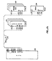
- Figures 1a and 1b show the basic structure of an encoder and a decoder, respectively, according to the present invention.
- the encoder shown in Figure 1a comprises time-domain signal input 100, signal sampler and quantizer 101, signal sample buffer 102, analysis-window multiplier 103 which modulates each digitized time-domain signal block, digital filter bank 104 which transforms the quantized signal into frequency coefficients, block-floating-point encoder 105 which converts each integer-valued transform coefficient into a floating-point representation, adaptive bit allocator 106 which assigns bits to the representation of each transform coefficient according to the total signal's spectral composition, uniform quantizer 107 which rounds each transform coefficient to an assigned bit length, and formatter 109 which assembles the coded frequency coefficients into a bit stream for transmission or storage.
- Figure 1a depicts a transmission path 110, however, it should be understood that the encoded signal may be stored for later use.
- the decoder shown in Figure Ib comprises encoded bit-stream signal input 111, deformatter 112 which extracts each encoded frequency coefficient from the assembled bit stream, linearizer 113 which converts each encoded coefficient into an integer-valued transform coefficient, inverse digital filter bank 114 which transforms the transform coefficients into a time-domain signal block, synthesis-window multiplier 115 which modulates the time-domain signal block, signal block overlap-adder 116 which recovers a digitized representation of the time-domain signal, analog signal generator 117, and analog signal output 118.
- a practical implementation of a preferred embodiment of a single-channel encoder employing either a 44.1 kHz or a 48 kHz sample rate, utilizes a 16-bit analog-to-digital converter (ADC) with a cycle time of no more than 20 microseconds to quantize the input time-domain signal.
- ADC analog-to-digital converter
- Each 16-bit digitized sample is used to form the 16 most-significant bits of a 24-bit word which is used in subsequent computations.
- a Motorola DSP56001 24-bit digital-signal processor (DSP) operating at 20.5 MHz with no wait states is used to perform the required computations and to control the encode and decode processes.
- Static random access memory (RAM) provides program and data memory for the DSP.
- a 16-bit digital-to-analog converter (DAC) with a cycle time of no more than 20 microseconds is used to generate an analog signal from the decoded digital signal.
- the encoder hardware architecture is comprised of analog signal input 200, low-pass filter (LPF) 200A, ADC 201, DSP 202, static RAM 203, erasable programmable read-only memory (EPROM) 204, and encoded serial-signal output 206.
- LPF 200A a low-pass filter which is not shown in Figure 1a
- ADC 201 digitizes (samples and quantizes) the incoming signal into a serial stream of 16-bit words.
- DSP 202 receives and buffers the serial stream of digitized samples, groups the samples into blocks, performs the calculations required to transform the blocks into the frequency domain, encodes the transform coefficients, formats the code words into a data stream, and transmits the encoded signal through serial data path 206.
- the programming and data work areas for the DSP are stored in two 24 kilobyte (KB) banks of static RAM 203 which is organized into two sets of 8,192 24-bit words.
- the DSP requires fast-access-time program memory which can be implemented more cheaply in RAM than it can be in programmable ROM. Consequently, EPROM 204 stores programming and static data in a compressed format which the DSP unpacks into a usable form into RAM 203 when the encoder is first powered on.
- Figures 2b and 2c provide more detail on two DSP interfaces.
- Figure 2b shows the serial-communication interface for DSP 202, ADC 201, and serial data path 206.
- Line SC0 clocks a serial-bit stream of digitized input signal samples along line SRD from ADC 201 into DSP 202.
- Line SC1 provides the frame-synchronization signal to the ADC and the DSP which marks the beginning of each 16-bit word.
- Line SCK clocks a serial-bit stream of the encoded signal along line STD from the DSP to serial data path 206.
- Figure 2c shows the memory addressing interface.
- Memory for the Motorola DSP56001 is divided into three segments: program, X data, and Y data.
- One bank of RAM which contains program memory, is selected whenever the DSP brings line PS low.
- a second bank contains data memory, which is selected whenever line DS is brought low.
- the DSP selects between X data and Y data memory by raising line XY high or bringing line XY low, respectively.
- X data and Y data memory are mapped into separate address spaces by attaching line XY to address line A12.
- Inverter 205C allows DSP 202 to select either RAM or EPROM according the state of address line A15.
- inverter 205C sets the chip-select (CS) lines of RAM 203 and EPROM 204 low. Only EPROM 204 is selected when CS is low.
- inverter 205C sets the CS lines of RAM 203 and EPROM 204 high. Only static RAM 203 is selected when CS is high.
- the decoder hardware architecture is comprised of encoded serial-signal input path 207, DSP 208, static RAM 209, EPROM 210, DAC 212, LPF 213A, and analog signal output 213.
- DSP 208 receives and buffers the encoded signal, deformats the signal into the encoded transform coefficients, performs the calculations required to transform the coefficients into the time domain, groups the coefficients into time-domain blocks, overlap-adds the blocks into a time-domain sequence of digital samples, and transmits the digital samples in a serial-bit stream to DAC 212.
- the programming and data work areas for the DSP are stored in two 24 KB banks of static RAM 209 which is organized into two sets of 8,192 24-bit words.
- EPROM 210 stores in a compressed format programming and static data which the DSP unpacks into usable form into RAM 209 when the decoder is first powered on.
- DAC 212 generates an analog signal corresponding to the serial-data stream received from the DSP.
- LPF 213A (a low-pass filter which is not shown in Figure 1b) insures signal output 213 is free of any spurious high-frequency components created by the encode/decode process.
- Figure 2e shows the serial-communication interface for DSP 208, serial-signal input path 207, and DAC 212.
- Timing generator 208A using a phase-locked loop circuit to extract a timing reference from the encoded serial-bit input signal, generates the receive clock, frame-synchronization, and transmit clock signals for the decoder.
- Line SC0 clocks the encoded serial-bit signal along line SRD into DSP 208.
- Line SCK clocks a serial-bit stream of the decoded digitized signal samples along line STD from DSP 208 to DAC 212.
- Line SC2 provides a frame-synchronization signal to the DAC and to the DSP which marks the beginning of each 16-bit word.
- the interface between DSP 208 and the memory-address bus is implemented in the same manner as that described above for the encoder. See Figure 2c.
- the two-channel encoder requires LPF 200A and 200B, and ADC 201A and 201B, connected as shown in Figure 3a.
- the interface between the DSP and ADC components operates in a manner similar to that described above for a one-channel encoder.
- Timing generator 202A provides an additional signal to line SC2 of the DSP at one-half the rate of the frame-synchronization signal to control multiplexer 202B and indicate to the DSP which of the two ADC is currently sending digitized data.
- the two-channel decoder requires DAC 212A and 212B, and LPF 213A and 213B, connected as shown in Figure 3b.
- the interface between the DSP and DAC components operates in a manner similar to that described above for a one-channel decoder.
- Timing generator 208A provides an additional signal to line SC1 of the DSP at one-half the rate of the frame-synchronization signal to control demultiplexer 208B and indicate to the DSP which of the two DAC is currently receiving digital data.
- the basic hardware architecture may be modified. For example, one Motorola DSP56001 operating at 27 MHz with no wait states can implement a two-channel encoder or decoder. Additional RAM may be required.
- specialized hardware may be used to perform certain functions such as window modulation or the Fast Fourier Transform (FFT).
- FFT Fast Fourier Transform
- the entire encoder/decoder may be implemented in a custom-designed integrated circuit. Many other possible implementations will be obvious to one skilled in the art.
- signal sampler and quantizer 101 is an analog-to-digital converter which quantizes the input signal into 16 bits which are subsequently padded on the right with 8 zero bits to form a 24-bit integer representation. All subsequent transform calculations are performed in 24-bit integer arithmetic.
- the analog input signal should be limited in bandwidth to at most 15 kHz (20 kHz for a 20 kHz bandwidth coder). This may be accomplished by a low-pass filter not shown in Figure 1a.
- a music signal with at least Compact Disc (CD) quality has, in addition to other qualities, a bandwidth in excess of 15 kHz. From the Nyquist theorem, it is known that a 15 kHz bandwidth signal must be sampled at no less than 30 Khz.
- a sample rate of 44.1 Khz is chosen for one embodiment of an encoder according to the present invention because this rate is used in CD applications and such a choice simplifies the means necessary to use an encoder according to the present invention in such applications. (This sample rate also supports an alternative 20 kHz bandwidth embodiment of an encoder according to the present invention.)
- sampling rates such as 48 kHz which is a rate common to many professional audio applications, may be utilized. If an alternate rate is chosen, the frequency separation between adjacent transform coefficients will be altered and the number of coefficients required to represent the desired signal bandwidth will change. The full effect that a change in sampling rate will have upon the implementation of an encoder according to the present invention will be apparent to one skilled in the art.
- the encoder and decoder structures shown in Figures 1a and 1b is comprised of 256 frequency bins.
- the bandwidth of each bin is equal to 86.1 Hz (or 44.1 kHz / 512). (For some discrete transforms bin 0, the DC or zero frequency component, has a bandwidth equal to half of this amount.) Only coefficients 0-182 are used to pass a 15.6 kHz signal.
- Figures 6a through 6d illustrate how a block is modified or weighted such that the samples near the block edges are close to zero.
- the multiplier circuit shown in Figure 6a modulates the sampled input signal x(t) shown in Figure 6b by the weighting function shown in Figure 6c.
- the resultant signal is shown in Figure 6d. This process is represented by box 103 in Figure 1a.
- This weighting function is a sample-by-sample multiplication of the signal sample block, and has been the subject of considerable study because its shape has profound affects upon digital filter performance. See, for example, Harris, "On the Use of Windows for Harmonic Analysis with the Discrete Fourier Transform," Proc. IEEE, vol. 66, 1978, pp. 51-83. Briefly, a good window increases the steepness of transition band rolloff for a given level of depth of stopband rejection, and permits correction of its modulation effects by overlapping and adding adjacent blocks. Window design is discussed below in more detail.
- a discrete transform implements digital filter bank 104 shown in Figure 1a. Filtering is performed by converting the time-domain signal sample blocks into a set of time varying spectral coefficients. Any one of several transform techniques may be used to implement the filter bank.
- the transform technique used in one embodiment of an encoder and a decoder according to the present invention was first described in Princen and Bradley, "Analysis/Synthesis Filter Bank Design Based on Time Domain Aliasing Cancellation," IEEE Trans. on Acoust., Speech, Signal Proc., vol. ASSP-34, 1986, pp. 1153-1161. This technique is the time-domain equivalent of an evenly-stacked critically sampled single-sideband analysis-synthesis system.
- E-TDAC Evenly-Stacked Time-Domain Aliasing Cancellation
- An alternative form of the TDAC transform may be used in another embodiment of an encoder and a decoder according to the present invention. The technique is described in Princen, Johnson, and Bradley, "Subband/Transform Coding Using Filter Bank Designs Based on Time Domain Aliasing Cancellation," ICASSP 1987 Conf. Proc., May 1987, pp. 2161-64. This alternate transform is the time-domain equivalent of an oddly-stacked critically sampled single-sideband analysis-synthesis system. It is referred to herein as Oddly-Stacked Time-Domain Aliasing Cancellation (O-TDAC).
- O-TDAC Oddly-Stacked Time-Domain Aliasing Cancellation
- E-TDAC utilizes a transform function which is equivalent to the alternate application of a modified Discrete Cosine Transform (DCT) with a modified Discrete Sine Transform (DST).
- the E-TDAC transform alternately produces one of two sets of spectral coefficients or transform blocks for each signal sample block.
- the computation algorithm used is the Fast Fourier Transform (FFT). See Cooley and Tukey, "An Algorithm for the Machine Calculation of Complex Fourier Series," Math. Comput., vol. 19, 1965, pp. 297-301.
- FFT Fast Fourier Transform
- a single FFT can be used to perform the DCT and DST simultaneously by defining them respectively as the real and imaginary components of a single complex transform.
- This technique exploits the fact the FFT is a complex transform, yet both input signal sample blocks consist only of real-valued samples.
- the DCT coefficients emerge from the transform as the set of real values and the DST coefficients are represented by the set of imaginary values. Therefore the DCT of one signal sample block can be concurrently calculated with the DST of another signal sample block by only one FFT followed by complex array multiplication and additions.
- two adjacent signal sample blocks are stored in buffers and transformed together into a DCT/DST block pair.
- the block pair is subsequently quantized and formatted for transmission or storage.
- concurrent processing may be accomplished by processing a signal sample block from each of the two channels: a DCT block is generated for one channel, and a DST block is generated for the second channel.
- the coded blocks for a given channel alternate between the DCT and DST (see expression 5), and are always of the opposite type from that of the other channel's blocks.
- a pair of blocks, one for each channel, are transformed and formatted together.
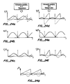
- quantized input signal x(t) is grouped into blocks.
- Signal x c (t) is input to the DCT.
- Another set of blocks of the sampled input signal x(t), which overlap the first set by one-half block length, are windowed by window function W s shown in Figure 14c (which window function is identical to W c but shifted in time by one-half block length) producing signal x s (t) shown in Figure 14e and subsequently passed to the DST.
- phase term m in equations 1 and 2 controls the phase shift of the time-domain aliasing distortion.
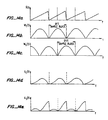
- Figures 15a-15d and 16a-16g illustrate this distortion.
- Signal y c (t) recovered from the inverse DCT, is shown in Figure 15a.
- Figure 15b illustrates that the recovered signal is composed of two components: the original windowed signal (solid line), and time-domain aliasing distortion (dotted line).
- Figures 15c and 15d illustrate similar information for signal y s (t) recovered from the inverse DST.
- E-TDAC requires the aliasing to be as follows.
- the time-domain alias component consists of the first half of the sampled signal reversed in time about the one-quarter point of the sample block, and the second half of the sampled signal reversed in time about the three-quarter point of the sample block.
- the alias component is similar to that for the DCT except its amplitude is inverted in sign. See Figures 15b and 15d.
- FIGS 16a-16g illustrate the overlapping of signal sample blocks and the resulting cancellation of alias distortion.
- Signals y c (t) and y s (t) shown in Figure 16a and 16d, recovered from the inverse DCT and DST, are modulated by window functions W c (t) and W s (t) respectively, shown in Figures 16b and 16e, to produce signals y c (t) and y s (t) shown in Figures 16c and 16f.
- the overlapped blocks of these windowed signals are added, the alias components are cancelled and the resulting signal y(t) shown in Figure 16g is an accurate reconstruction of the original input signal x(t).
- Each transform coefficient derived from filter bank 104 is encoded and grouped into subbands by nonuniform quantizer 108.
- Tables I and II show the assignment of transform coefficients to subbands.
- the nonuniform quantizer is composed of block-floating-pointencoder 105, adaptive bit allocator 106, and uniform quantizer 107 shown in Figure 1a. Quantization is performed for transform block pairs: either two adjacent blocks in a one-channel system, or one block from each channel of a two-channel system.
- nonuniform quantization is comprised of five major sections: (1) calculating subband exponents, (2) determining the master exponents, (3) initially setting the bit length of each coefficient code word as a function of the coefficient's frequency, (4) adaptively allocating additional bits to specific code words, and (5) rounding and truncating the code word according to the bit length computed from the sum of the adaptive bit allocations and the minimum bit length based on the coefficient's frequency.
- Floating-point representation of numerical quantities is well known in the art of digital data processing and is used to represent a wider range of values with fewer bits than is possible with integer representation.
- a float-ing-point number is composed of a mantissa and an exponent.
- the mantissa is a signed integer-valued expression expressed in two's complement form.
- the corresponding exponent is an unsigned value equal to the power of two of the multiplier required to convert the mantissa (either normalized or unnormalized) into the true value of the represented numerical quantity.
- a positive nonzero mantissa is said to be-normalized when its most significant data bit is nonzero.
- a negative-valued mantissa is normalized when its most significant data bit is zero.
- a normalized mantissa insures the greatest number of significant bits for the numerical quantity is contained within the mantissa's limited bit length.
- Block-floating-point representation is also well known in the art and is used to represent a set of floating-point numbers with fewer bits than is possible with conventional floating-point representation.
- This technique uses one exponent for a group of mantissas. Some mantissas in the group may not be normalized. The mantissa for the quantity with the largest magnitude in the group will be normalized provided it is not too small, i.e., the exponent is incapable of expressing the multiplier required for normalization. Whether the mantissas are normalized or not, however, the exponent always represents the number of times each integer-valued mantissa in the group must be shifted to the right to obtain the true value of the floating-point quantity.
- the block-floating-point encoder comprises sections one and two of the nonuniform quantizer.
- the functions performed by the first section are shown in box 701 of Figure 7.
- This section calculates the subband exponents for each of several subband frequency coefficients.
- the subbands are shown in Table I.
- the procedure is comprised of three steps. The first step finds the largest transform coefficient in each subband within one transform block and determines the number of left shifts required to normalize these largest 24-bit coefficients. The second step determines corresponding shift values for a second transform block. The third step compares the shift value for each subband in the first transform block with the corresponding subband's shift value in the second transform block, selects the smaller of the two, and saves it as the exponent for the appropriate subband in both blocks. The exponents are shared by the coefficient mantissas in each transform block.
- the second section of the nonuniform quantizer determines the value of a one-bit master exponent for each of two subband groups.
- the master exponent is used to expand the dynamic range of the coder. Referring to Table I, it may be seen that master exponent MEXP0 represents the low frequency subbands zero through eighteen. Master exponent MEXP1 represents high frequency subbands nineteen through thirty six. (For a 20 kHz coder, three additional subbands are required as shown in Table II.) If all subband exponents in a group are three or greater, the master exponent for that group is set to one and all subband exponents in that group are reduced by three.
- a master exponent When a master exponent is set to one, it indicates that all coded coefficients within all subbands in the group are shifted to the left three more times than is indicated by the subband exponent values. When a master exponent is zero, each subband exponent in the group correctly represents the total left shifts for each transform coefficient in the subband. These master exponents permit using shorter subband exponents while allowing for a sufficient dynamic range. This step in the process is shown in boxes 702a and 702b of Figure 7.
- An additional step can be taken which may reduce the total bits required to represent the coded signal.
- the sign bit of a normalized mantissa is superfluous. As discussed above, the sign bit and the most significant data bit in a normalized mantissa are always of opposite value. The sign bit can therefore be dropped by the encoder and restored by the decoder. The dropped sign bit is referred to herein as a "hidden bit.”
- Whether a mantissa is normalized can be determined by examining the exponent. If the exponent is less than its maximum value (which is 15 after adjusting for the master exponent in the floating point scheme used in the preferred embodiment), the mantissa is normalized. If the exponent is equal to its maximum value, no conclusion can be drawn, therefore it is assumed the mantissa is not normalized and there is no hidden bit.
- This technique can be used only for those mantissas which have their own unique exponent.
- only DCT subband zero meets this requirement it is comprised of only one transform coefficient and it does not share its exponent with a subband in the paired DST block.
- the hidden bit technique may be used for all subbands containing only one coefficient.
- the reduction in bit requirements is reflected in the fixed bit length for DCT coefficient zero.
- the "minimum" bit length of coefficient C(0) is 8 bits. If the hidden bit technique were not utilized, the fixed length for C(0) would be identical to that for coefficient S(0), or 9 bits. In situations where coefficient C(0) is unnormalized, the reduced bit length is not likely to created audible quantization noise because the frequency component will be of very low amplitude.
- the third section of the nonuniform quantizer sets an initial minimum bit length for the representation of each left-shifted transform coefficient. This length is set according to the coefficient's frequency.
- Box 703 in Figure 7 represents this section of the process and Table I shows the minimum number of bits fixed for each coefficient's code word. The minimum bit length was derived by comparing a representative filter bank response curve to a psychoacoustic masking threshold curve. Because filter performance is a function only of the difference in frequency between a signal and the coefficient's frequency, any frequency coefficient may be used to represent the filter bank's response.
- the response curve shown in Figure 9 is obtained from the root mean square average of the filter's response to a range of frequencies within the filter passband.
- filter selectivity is affected by the shape of the analysis window and the number of samples in each time-domain signal block. It may be noted here that the overall coder characteristic response is not as good as that shown in Figure 9 because an additional selectivity loss occurs during the signal synthesis process. This effect is discussed below and is also shown in Figures 17a and 17b.
- Figure 10 compares the filter response against the 4 kHz psychoacoustic masking curve. Because coder bandwidth and selectivity improve relative to the psychoacoustic masking curve as frequency increases, fewer bits are required to represent higher frequency transform coefficients. This relationship is reflected in the minimum bit length values as shown in Table I.
- Figure 11 compares the 1 kHz masking curve against the filter response curve which is offset such that the psychoacoustic masking curve is always higher.
- the offset for the filter response is due to the increased accuracy afforded by additional bits reserved for the lower-frequency coefficients. Each additional bit improves the signal-to-noise ratio approximately 6 db.
- the graph in Figure 11 indicates an offsetof 8 db (or approximately 1.3 additional bits of accuracy) may be necessary to encode a low-frequency transform coefficient if no other tones are present to contribute to the masking effect.
- Figure 12 shows a composite masking curve derived from a simple overlay of the individual masking curves of three tones. Empirical evidence indicates that even this composite curve is very conservative, understating the actual masking effect of multiple tones. Furthermore, music is generally a more complex signal than a few discrete frequencies, and the resulting increase in masking levels permits a reduction in the required accuracy of transform coefficient code words.
- the E-TDAC coder would generate quantization noise at a frequency equal to the sample block rate whenever an input signal channel contains low-frequency spectral components whose period is large compared to the sample block length. This noise would be created within the channel containing such low-frequency components by the interaction of two mechanisms.
- the E-TDAC transform would convert the low-frequency components into an alternating sequence of nonzero and zero values for coefficient zero (DCT C(0) and DST S(0)). Coefficient C(0) would be nonzero in the DCT transform blocks but coefficient S(0) would always be zero in the DST transform blocks.
- Coefficient one (DCT C(1) and DST S(1)) would be affected to a lesser extent due to the filter bank's sidelobe leakage.
- the allocation algorithm for the channel would toggle between two bit-assignment patterns, one for DCT blocks and the other for DST blocks. Because the number of adaptively assigned bits is fixed, bits assigned to coefficient C(0) in the DCT blocks would not be available for allocation to other transform coefficients as they would be in the DST blocks. (Because the value of coefficient S(0) is always zero, it would not be assigned any adaptively allocated bits.) This alternating allocation pattern would manifest itself as audible quantizing noise at a frequency equal to the sample block rate of 86.1 Hz (or 44.1 kHz / 512).
- the preferred embodiment of an encoder according to the present invention assigns a fixed bit length of 8 bits to DCT coefficient C(0) and 9 bits to DST coefficient S(1) (see Table I) and excludes them from adaptive bit allocation. This exclusion prevents the adaptive allocation scheme from generating the quantization noise described in the previous paragraph.
- the fourth section of the nonuniform quantizer performs the adaptive bit allocation.
- Box 704 in Figure 7 provides an overview of this allocation process.
- bit allocation assigns a fixed number of additional bits to specific coefficients in four phases. The number of bits may be chosen to balance signal coding quality and transmission bit rate.
- the allocation limit is set at 133 bits per transform block to achieve a total bit-rate of 128 kBits per second. In an application using error correction codes (discussed below), the limit must be reduced to 124 bits per transform block to maintain the same bit rate. This limit is referred to herein as the allocation maximum or as the number of allocable bits.
- the current implementation assigns a maximum of 4 bits per coefficient. This maximum represents a design compromise between coding accuracy and total bit rate. It will be realized by one skilled in the art that this maximum and the total number of adaptively allocable bits may be altered without changing the concept or basic purpose of the invention.
- Phase zero is an initialization process for the remaining phases.
- Phase one assigns bits, up to a maximum of four per transform coefficient, to the coefficients within the same critical band of those frequency components with the greatest spectral energy. If all allocable bits are assigned during phase one, the allocation process stops. If not, phase two allocates additional bits to the transform coefficients which were allocated bits during phase one such that the total adaptively allocated bits for each coefficient is four. If all allocable bits are assigned during phase two, the allocation process stops. If any bits remain, phase three allocates bits to those coefficients which are adjacent to coefficients thatwere allocated bits during phase one and two. Amore detailed conceptual description of this procedure is provided in the following paragraphs. The actual logic implementation of the procedure is discussed later.
- Figure 8 is a diagram of the conceptual process used to adaptively allocate bits to specific transform coefficients.
- the initialization steps of phase zero are shown in box 800.
- the first step initializes the elements of an array A() to zero.
- the next step identifies the smallest subband exponent, which is the exponent for the subband with the largest spectral component, and saves the value as X MIN . All subband exponents are subtracted from X MIN and the difference is stored in array M(). Note that the smallest possible subband exponent is zero and the largest possible subband exponent is eighteen, which is the sum of a maximum value of fifteen for a 4-bit high frequency subband exponent plus the value of three for the master exponent MEXPI. See Table I.
- array M() consists of a set of elements, one for each subband, whose values range from zero to four.
- the elements with a value of four represent those subbands where at least one of the coefficients in the subband has one of the largest spectral coefficients in the total signal.
- Each element in A() corresponds to a subband.
- each element of A() represents the number of bits assigned to all transform coefficients in the corresponding subband.
- subband 13 represents coefficients 13-14. If element A(13) has a value of one, this indicates that 2 bits are allocated, one each to transform coefficients 13 and 14. Continuing the example, if element A(36) has a value of two, then 30 bits are allocated, 2 bits each to coefficients 168-182.
- the number of allocated bits is deducted from the number of bits remaining for allocation.
- each element of M() is examined in turn. As many as four passes are made through array M(), or until all allocable bits are allocated. On the first pass, each element in array A() is incremented by one if the corresponding element in array M() has a value equal to four. The second pass increments by one each element in A() which corresponds to each element in M() which has a value equal to three or four. On the third pass, array A() elements are incremented if the corresponding M() element has a value within the range of two to four.
- the final pass increments those elements in array A() corresponding to those M() elements which have a value in the range between one and four. It may be noted that if the elements in array M() sum to the allocation limit or less, the contents of arrays M() and A() at this point will be identical. If the number of bits assigned has reached the allocation limit, the bit-allocation process is complete at the end of phase one.
- phase two shown in box 802 of Figure 8.
- This phase makes as many as three passes through array A(), stopping earlier if and when the maximum allocable bits are assigned. Each pass starts with the lowest frequency element (A(1) for DCT blocks, or A(2) for DST blocks) and works upward in frequency. On the first pass through array A(), each element which has a value between one and three is incremented by one. On the second pass, elements with values of two or three are incremented. On the third pass, elements equal to three are incremented. If this phase completes without exceeding the allocation limit, every element in array A() will have a value of either four or zero.
- phase three allocation will terminate as soon as the allocation limit has been reached.
- This final phase assigns additional bits to transform coefficients with lower spectral energy which are adjacent to subbands of coefficients with higher energy. This assignment is accomplished in three steps.
- the first step scans array A() starting with the highest frequency element A(36) (element A(39) is the starting element in 20 kHz bandwidth coders) in search of a group of two adjacent elements which have the values ⁇ 0,4 ⁇ . If found, the element whose value is zero is set to one such that the group values become ⁇ 1,4 ⁇ .
- step two of phase three begins by scanning array A() downward starting with the highest frequency subband in search of a group of two adjacent elements which have the values ⁇ 4,0 ⁇ . If found, the zero-valued element is set to one to produce values ⁇ 4,1 ⁇ .
- the third and final step of phase three allocates additional bits to the coefficients in subbands assigned bits in steps one and two of this phase. Starting at the highest frequency element of array A(), each element modified in step one is incremented. Finally, elements modified in step two are incremented, starting with the highestfrequency subbands. This third step reiteratively increments the array elements in the same order discussed above until all allocable bits are assigned, or until all of the elements modified in steps one and two are assigned a total of 4 bits each. If the latter condition is met and any allocable bits remain to be assigned, phase three repeats starting with step one.
- Phase zero begins by initializing all elements of array A() equal to zero, and constructing four tables T 1 through T 4 .
- the construction of the tables is accomplished through the following steps: (1) identify the smallest subband exponent and save this value as X MIN ; (2) starting with the lowest frequency subband (subband 1 for DCT blocks, or subband 2 for DST blocks), subtract the subband exponent (see Table I) from X MIN ; (3) if the difference is zero, insert the subband number into tables T 1 , T 2 , T 3 , and T 4 ; (4) if the difference is negative one, insert the subband number into tables T 1 , T 2 , and T 3 ; (5) if the difference is negative two, insert the subband number into tables T 1 , and T 2 ; (6) if the difference is negative three, insert the subband number into table T 1 ; (7) continue steps three through six for each subband until all subbands have been processed.
- table T 1 contains the numbers of all subbands that have exponents in the range X MIN -3 to X MIN
- table T 2 contains subbands with exponents from X MIN -2 to X MIN
- table T 3 contains subbands with exponents from X MIN -1 to X MIN
- table T 4 contains subbands with exponents equal to X MIN .
- subband entries in each table are in ascending order according to frequency.
- Phase one allocates bits to transform coefficients in subbands with the largest subband exponents. Starting with the first (lowest frequency) entry in table T 4 , one bit is allocated to each transform coefficient within each subband represented in the table. The allocation is repeated in turn for table T 3 , T 2 , and finally table T 1 . This process continues until all allocable bits have been assigned or until all entries in tables T 4 to T 1 have been processed. As a bit is assigned to all coefficients in a subband, an entry in array A() corresponding to that subband is incremented by one such that the elements in A() reflect the total bits allocated to each transform coefficient in each subband.
- allocation terminates immediately when all of the allocable bits are assigned.
- Each-table entry represents a subband which, in general, contains multiple transform coefficients. Therefore, if the last of the allocable bits are assigned to a table entry representing a subband with more than one coefficient, it is probable that not all of the coefficients in that subband can be allocated the same number of bits. In such situations, the allocation process notes which coefficients in the subband must have a bit deducted from the subband's allocation amount subsequently stored in array A().
- table T 1 contains the numbers of all subbands that have exponents equal to X MIN -3
- table T 2 contains subbands with exponents equal to X MIN -2
- table T 3 contains subbands with exponents equal X MIN -1
- table T 4 contains subbands with exponents equal to X MIN .
- the entries in all of the tables are in ascending order according to the frequency of the transform coefficient.
- Phase two assigns bits to all coefficients represented by subbands in tables T 3 to T 1 until each coefficient has received a total of four additional bits, or until the allocation limit has been reached.
- one bit is assigned to each coefficient contained within each subband represented in the table.
- the entry is removed from table T 3 and inserted into table T 4 .
- coefficients associated with entries in table T 2 are allocated an additional bit, moving each entry from table T 2 to T 3 as the additional bit is assigned.
- entries in table T 1 are processed, moving the entries from table T 1 to T 2 . If any allocable bits remain, allocation continues by repeating the process for table T 3 , and then table T 2 .
- table T 4 contains all of the coefficients, each having received 4 bits, and tables T 3 through T 1 are empty. If all allocable bits have been assigned, array A() is rebuilt from the information contained in tables T 1 through T 4 to reflect the total bits allocated to each transform coefficient. Each element in array A() corresponding to an entry in table T 4 is assigned a value of four. Each A() element corresponding to an entry in table T 3 is assigned a value of three; for table T 2 a value of two; and for table T 1 a value of one. All other elements of A(), i.e., those subbands which are not represented by entries in tables T 1 through T 4 , are zero.
- Table T 4 is sorted, ordering the subband numbers into descending frequency.
- the first step adds subbands to table T 1 which are not in table T 4 that are lower in frequency and adjacent to subbands which are in table T 4 .
- Starting with the first (highest frequency) entry in table T 4 adjacent entries in the table are examined to determine if they are separated by one or more subbands. If they are, the number of the subband immediately below the higher subband is inserted into table T 1 . For example, suppose two adjacent entries in table T 4 represent subbands 16 and 12. These two subbands are separated by three subbands. Therefore the number 15, representing the subband below subband 16, would be inserted into table T 1 .
- the second step adds subbands to table T 1 which are not in table T 4 that are higher in frequency and adjacent to subbands which are in table T 4 .
- adjacent entries in the table are examined to determine if they are separated by one or more subbands. If they are, the number of the subband immediately above the lower subband is inserted into table T 1 . For example, suppose two adjacent entries in table T 4 represent subbands 16 and 12. As discussed above, these two subbands are separated by 3 subbands. Therefore the number 13, representing the subband above subband 12, would be inserted into table T 1 .
- each transform coefficient code word is rounded off to a bit length equal to the value of the element of array A() representing the subband in which the coefficient is grouped. Some coefficients in one subband, however, may have one bit deducted from their length as required to keep the total number of allocated bits equal to the allocation maximum.
- the fifth section of the nonuniform quantizer follows the adaptive bit allocation routine. Using the subband and master exponents determined in previous sections, each transform coefficient in a transform block is shifted to the left a number of times equal to the value of the exponent for the subband in which the coefficient is grouped, plus three more shifts if the associated master exponent is set to one. Each coefficient's total bit length is then calculated by adding its minimum bit length (see Table I) to the number of adaptively allocated bits assigned to coefficients in each subband, found in array A(). Each transform coefficient code word is rounded off to this bit length.
- each element of array A() represents the number of bits assigned to all coefficients within a subband. Some coefficients in one subband may have one bit deducted from their length as required to keep the total number of bits allocated to the transform block equal to the allocation maximum.
- the formatting process prepares a pair of encoded transform blocks for transmission or storage. This process is represented by box 109 in Figure 1a.
- the following description discusses the formatting of two adjacent transform blocks in a one-channel system. The same technique is used to format one transform block from each channel of a two-channel system processing signals such as that used in stereophonic applications.
- a fixed length representation of each transform coefficient code word is formed by truncating the rounded code word to a length equal to the minimum bit length shown in Table 1. Any additional bits allocated to the code word are formatted separately in an adaptive bit block.
- the master exponents, subband exponents, truncated coefficient code words, and adaptive bit blocks are then assembled according to the grouping shown in Figure 20. Note that one set of master and subband exponents applies to both transform blocks in the block pair. (See the discussion of the nonuniform quantizer above.) By sharing exponents between each pair of blocks, the total number of bits required to represent the exponents for both transform blocks is reduced by 50%.
- the formatted frame of transform blocks in Figure 20 depicts a structure where transform block A is a DCT block and block B is a DST block. If the frame will be subject to bit errors such as those caused by noise during transmission, error correction codes are intermixed with the data as shown in Figure 21. Additional overhead bits may be required, such as frame synchronization bits if the digital signal is intended for transmission, or database pointers or record keys if the frames are intended for storage. If frame synchronization bits are required, the formatted frame is randomized using a technique described in Smith, Digital Transmission Systems, New York, NY: Van Nostrand Reinhold Co., 1985, pp. 228-236. Randomization is performed to reduce the probability that valid data within the frame will be mistaken for the synchronization pattern. The randomized frame is then appended to the frame synchronization bits.
- each transform coefficient may be represented in as many as two distinct parts or segments.
- the first part represents the coefficient's minimum length and is composed of a fixed numberof bits. See Table I.
- the second part of the representation if present, is of varying length and is composed of the adaptively allocated bits. This two-part representation scheme is chosen over one which represents each coefficient as a variable length word because it is more immune to corruption by noise. If a noise burst occurs in a frame utilizing the preferred scheme, the effects of the noise will be confined to the value of the exponents, code words, or allocated bits directly affected by the noise. If a noise burst occurs in a frame utilizing variable length code words, the effects of the noise can be propagated through the remainder of the frame.
- This propagation may occur because the noise burst will alter not only the value of the exponents and code words hit directly by the noise, but also the information needed to determine the length of each variable length code word. If the length of one code word is in error, the remainder of the frame will be misinterpreted.
- An encoded DCT transform block includes 183 coefficient mantissas comprising 537 bits (see Table I) and 133 adaptively allocated bits, for a total of 670 bits. Because DST coefficient S(0) is always zero (see Table I and expression 4), it need not be transmitted or stored. Therefore, the DST block mantissas and allocated bits comprise only 666 bits. The two master exponent bits and 37 subband exponents of 148 bits brings the DCT/DST block pair length to 1486 bits. (For the 20 kHz embodiment, the total block-pair length is 1702 bits.)
- the deformatting process is able to determine the proper allocation from the transmitted subband exponents by performing the same allocation algorithm as that used in the encoding process.
- a preferred structure for formatting a frame of transform blocks is one which places the exponents first, coefficient code words second, and finally the adaptively allocated bits. This reduces processing delays because, after all subband exponents have been received, the deformatting process is able to determine bit allocations made to each transform coefficient while the adaptive bit blocks are being received.
- the formatting structure used in the preferred embodiment of an encoder according to the present invention is shown in Figure 20.
- the bit stream is formatted with the master and subband exponents in ascending frequency order.
- the fixed-length portion of the coefficient code words for transform block A are assembled in ascending frequency order, followed by the coefficient code words of transform block B.
- the adaptive bit blocks for block A are appended to the bit stream, followed by the adaptive bit blocks for block B.
- the total number of exponent and mantissa bits for one frame of a DCT/DST block pair is 1220 bits. Of this length, 150 bits are subband and master exponents.
- One (21,19) Reed-Solomon error correction code is added to the bit stream.
- the code sixteen bits in length, provides single-symbol error detection/correction for as many as nineteen 8-bit symbols (bytes), or 152 bits. See, for example, Peterson and Weldon, Error-Correcting Codes, Cambridge, Mass: The M.I.T. Press, 1986, pp. 269-309, 361-362.
- 150 constitute the master and subband exponent bits (15 kHz version).
- the remaining error correction capacity is utilized by providing redundant protection for the two master exponents.
- a total of eighteen bits are required to represent the 16-bit error code and redundant master exponents.
- the Reed-Solomon codes process data in bytes, therefore the error codes, protected data, and unprotected data are grouped into 8-bit bytes for ease of processing.
- the ratio of protected data to unprotected data in each block-pair frame is approximately nine-to-one. This permits scattering protected data throughout the formatted frame, each 8-bit byte of protected data separated by eight bytes of unprotected data. See Figure 21. With this technique, a single burst error of as many as 65 bits may occur anywhere in the frame without corrupting more than one protected data byte. Therefore, protected data can be recovered from any single noise burst no longer than 65 bits in length.
- exponents and transform coefficient code words are assembled in ascending frequency order, and are followed by the adaptive bit blocks.
- Transmission media include public dissemination such as broadcasting, internal use such as studio monitoring or signal mixing, and interfacility or telephonic use via terrestrial or satellite links.
- Storage media include magnetic tape and magnetic or optical disks.
- a deformatting process takes place when the digitized and coded signal is received from transmission means 111 either by receipt of a transmitted signal or retrieved from storage.
- the process is represented by box 112 in Figure 1b. If the formatted frame of code words was randomized prior to transmission, the formatted frame is recovered by an inverse randomizing process. Then the frame is split into the component parts of each transform block: the master exponents, subband exponents, fixed length portion of transform coefficient code words, and adaptively assigned bits. Error correction codes, if present, may be used to rectify errors introduced during transmission or storage.
- Each of the master exponent bits are checked with its corresponding redundant bit to verify accuracy. If this check fails, i.e., a master exponent and its redundant counterpart are not equal, the value of the master exponent is assumed to be one. If the correct value of the master exponent is actually zero, this assumption will reduce the amplitude of all transform coefficients within the subbands grouped under the errant master exponent. This assumption produces less objectionable distortion than erroneously setting a master exponent to zero (when it should be one) which would increase the amplitude of all affected coefficients.
- the exponent for DCT coefficient C(0) is also checked to determine if any hidden bit adjustments are necessary.
- the adaptive bit allocation routine discussed above is used to process the exponents extracted from the received signal, and the results of this process are used to determine the proper allocation of the adaptive bit blocks to the transform coefficients.
- the portion of each transform coefficient whose length equals the minimum bit length plus any adaptively allocated bits are loaded into a 24-bit word and then shifted to the right a number of times equal to the value of the appropriate subband exponent plus three additional shifts if the associated master exponent is set to one. This process is represented by box 113 in Figure 1b.
- Box 114 in Figure Ib represents a bank of synthesis filters which transform each set of frequency-domain coefficients recovered from the deformatting and linearization procedures into a block of time-domain signal samples.
- An inverse transform from that used in analysis filter bank 104 in Figure 1a implements synthesis filter bank 114.
- the inverse transforms for the E-TDAC technique used in this embodiment of a decoder according to the present invention are alternating applications of a modified inverse DCT and a modified inverse DST. Because half of the transform blocks are omitted from transmission or storage (see expression 5), those blocks must be recreated for the inverse transforms.
- the missing DCT blocks may be recreated from the available DCT blocks as shown in equation 8.
- the missing DST blocks may be recreated as shown in equation 9.
- Calculations are performed using an FFT algorithm.
- the same techniques as those employed in the forward transform are used in the inverse transform to permit concurrent calculation of both the DCT and DST using a single FFT.
- Figures 14a-14e and 16a-16g illustrate the transform process of the analysis-synthesis filter banks.
- the analysis filter bank transforms the time-domain signal into an alternating sequence of DCT and DST blocks.
- the inverse transform applies the inverse DCT to every other block, and applies the inverse DST to the other half of the blocks.
- the recovered signal contains aliasing distortion. This distortion is cancelled during a subsequent time-domain block overlap-add process represented by box 116 in Figure 1b. The overlap-add process is discussed below.
- Figures 16a-16g illustrate cancellation of time-domain aliasing by the overlap-add of adjacent time-domain signal sample blocks.
- the E-TDAC transform requires the application of a synthesis window identical to the analysis window and an overlap-add of adjacent blocks. Each block is overlapped 100%; 50% by the previous block and 50% by the following block. Synthesis-window modulation is represented by box 115 in Figure 1b.
- Analysis-synthesis window design must consider filter bank performance. Because both windows are used to modulate the time-domain signal, the total effect upon filter performance is similar to the effect caused by a single window formed from the product of the two windows. Design of the analysis-synthesis window pair, therefore, is accomplished by designing a suitable product-window representing a point-by-point multiplication of the analysis and synthesis windows. This design is highly constrained, reducing flexibility in trading off the steepness of transition band rolloff and the depth of stopband rejection. As a result, filter performance is degraded to a greater extent than it is by an analysis-only window designed without this constraint. For example, see Figures 17a and 17b.
- An alpha value in the range of 4 through 7 is usable in the preferred embodiment of an encoder and a decoder according to the present invention.
- This range provides a good compromise between steepness of transition band rolloff at mid-frequencies (1-2 kHz), and depth of stopband rejection for low frequencies (below 500 Hz) and high frequencies (above 7 kHz).
- the range of acceptable alpha values was determined using computer simulations by identifying the lowest alpha values which have sufficient stopband rejection to keep quantizing noise below the psychoacoustic masking threshold.
- an analysis-synthesis product-window WP(n) of length N is derived by convolving window W(n) of length v+1 with a rectangular window of length N-v.
- the value v is the window overlap-add interval.
- the overlap-add process cancels alias distortion and the modulation effects of the analysis and synthesis windows.
- the convolution which derives the product window is shown in equation 13, where the denominator of the expression scales the window such that its maximum value approaches but does not exceed unity. This expression may be simplified to that shown in equation 14.
- the analysis and synthesis windows have a length of 512 samples with a 100% window overlap, or an overlap interval of 256 samples.
- Equations 20 through 23 express this requirement for a product-window created from the product of a pair of 512 sample analysis and synthesis windows with 100% overlap.
- Equation 20 represents the overlap of the first half of window WP k and the last half of the previous window WP k-1 .
- Equation 21 represents the overlap of the last half of window WP k and the first half of the following window WP k+1 .
- Equations 22 and 23 show the equivalent expressions in terms of the analysis window.
- Box 117 in Figure Ib represents a conventional digital-to-analog converter which generates a varying voltage analog signal in response to a digital input.
- the digital input is obtained from the 16 most significant bits of the 24-bit integer words produced by the overlap-add process.
- the analog output should be filtered by a low-pass filter with a passband bandwidth of 15 kHz (20 kHz for the 20 kHz coder) to remove spurious high-frequency components. This filter is not shown in Figure 1b.
- O-TDAC Oddly-Stacked Time-Domain Aliasing Cancellation
- O-TDAC utilizes a transform function which is a modified Discrete Cosine Transform (DCT), shown in equation 24.
- DCT Discrete Cosine Transform
- the computation algorithm used is the Fast Fourier Transform (FFT). Unlike the E-TDAC version, the O-TDAC implementation does not use a single FFT to concurrently transform two signal sample blocks. The computational complexity of the transform is reduced, however, by employing a technique similar to the premultiply-transform-postmultiply process used in the E-TDAC version.
- the premultiply step converts the real valued sequence of signal samples x(n) into a complex valued sequence by modulating the signal samples by the complex function exp - j ⁇ ⁇ ⁇ n N where
- a Discrete Fourier Transform implemented by a FFT transforms the modified signal samples into a set of transform coefficients. Because the FFT is a complex transform, the real and imaginary parts of the modified signal sample set can be transformed concurrently. Finally, a postmultiply step obtains the true DCT coefficients. This process is represented below in equations 27 and 28.
- X * k FFT ⁇ x n ⁇ exp - j ⁇ ⁇ ⁇ n N
- C k R k ⁇ cos 2 ⁇ ⁇ ⁇ k + 1 2 ⁇ m N + Q k ⁇ sin 2 ⁇ ⁇ ⁇ k + 1 2 ⁇ m N
- two consecutive overlapped signal sample blocks are stored in buffers and transformed together using two FFT processes into a DCT 1 /DCT 2 block pair.
- signal sample blocks from each of the two channels are transformed by two FFT processes into a DCT 1 /DCT 2 block pair.
- the O-TDAC technique can accurately recover an input signal from an alternating sequence of cosine transform blocks of the form C ⁇ 1 k 0 , C ⁇ 2 k 1 , C ⁇ 1 k 2 , C ⁇ 2 k 3 , where
- the O-TDAC transformation and alias cancellation process is very similar to that for the E-TDAC transform, and is illustrated in Figures 22a-22e, 23a-23d, and 24a-24g.
- the principal difference is the form of the alias component.
- the alias component is a time reversed image of the input signal about the onequarter point of the sample block, but the sign of its amplitude is inverted from that of the input signal.
- the aliasing is time reversed about the three-quarter point of the sample block with no change in sign. See Figures 23b and 23d.
- the nonuniform quantizer for the O-TDAC implementation is identical to that used with the E-TDAC transform implementation with only a few minor differences due to the fact only DCT blocks are present.
- both transform blocks include coefficient C(0), therefore, all subband exponents are shared by the two blocks. Consequently, there can be no hidden bit and the "minimum" bit length for coefficient C(0) is fixed at nine bits (as opposed to eight bits for E-TDAC). See Table Ill.
- Each encoded DCT block includes 183 coefficient mantissas comprising 538 bits (see Tables I and III) and 130 adaptively allocated bits, for a total of 668 bits each.
- the two master exponents and 37 subband exponents of 148 bits shared by both DCT blocks brings the DCT 1 /DCT 2 block pair length to 1486 bits, the same as that for the E-TDAC implementation.
- the structure of the formatted frame without error correction codes is very similar to that used in the E-TDAC implementation, and is shown in Figure 25.
- the frame structure with error correction codes is identical to that for E-TDAC, and is shown in Figure 21.
- the deformatting process is identical to that described above except no checks are made for any hidden bits.
- the O-TDAC implementation of the inverse transform reduces computational complexity by employing a similar premultiply-transform-post multiply process as that used in the forward transform.
- This process converts the real-valued DCT coefficients into a set of modified complex valued coefficients, concurrently transforms the real and imaginary parts of the modified coefficients using a single inverse FFT (IFFT), and obtains the time-domain signal from postmultiplication, as shown in the following equations.
- IFFT inverse FFT
- x * n IFFT ⁇ C k ⁇ exp - j ⁇ 2 ⁇ ⁇ ⁇ k ⁇ n N for 0 ⁇ n ⁇ N
- x ⁇ n r n ⁇ cos ⁇ ⁇ n + m N - q n ⁇ sin ⁇ ⁇ n + m N for 0 ⁇ n ⁇ N
Landscapes
- Engineering & Computer Science (AREA)
- Multimedia (AREA)
- Signal Processing (AREA)
- Physics & Mathematics (AREA)
- Theoretical Computer Science (AREA)
- Acoustics & Sound (AREA)
- General Physics & Mathematics (AREA)
- Health & Medical Sciences (AREA)
- Audiology, Speech & Language Pathology (AREA)
- Human Computer Interaction (AREA)
- Spectroscopy & Molecular Physics (AREA)
- Computer Networks & Wireless Communication (AREA)
- Computational Linguistics (AREA)
- Compression, Expansion, Code Conversion, And Decoders (AREA)
- Analogue/Digital Conversion (AREA)
- Transmission Systems Not Characterized By The Medium Used For Transmission (AREA)
- Reduction Or Emphasis Of Bandwidth Of Signals (AREA)
- Stereo-Broadcasting Methods (AREA)
- Compression Or Coding Systems Of Tv Signals (AREA)
- Stereophonic System (AREA)
Claims (14)
- Codeur pour le codage numérique de haute qualité d'une information analogique audio à large bande, comprenant:- un moyen de sous-bande pour la réception de ladite information analogique audio à large bande et pour la génération en réponse de blocs de sous-bande, chacun desdits blocs de sous-bande comprenant une information respective de sous-bande pour une pluralité de sous-bandes;- un moyen de quantification non uniforme pour grouper lesdits blocs de sous-bande en paires de blocs de sous-bande, formant alors une représentation de ladite information respective de sous-bande sous la forme de blocs à virgule flottante, pour le groupage desdites représentations en paires, chaque paire comprenant une représentation d'une information de sous-bande à partir de chaque bloc de sous-bande dans une paire respective de blocs de sous-bande, chaque représentation dans une paire respective de représentations partageant le même exposant, et pour la génération de mots codés par une allocation adaptative des bits et une quantification desdites représentations; et- un moyen de formatage pour assembler l'information numérique comprenant lesdits mots codés en une sortie numérique présentant un format adapté à la transmission ou au stockage.
- Codeur selon la revendication 1, dans lequel ledit moyen de sous-bande comprend un moyen pour l'échantillonnage et la quantification de ladite information analogique audio à bande large en blocs d'échantillonnage de signal dans le temps, un moyen pour la génération de blocs d'échantillonnage de signal dans le temps compensés par fenêtrage d'analyse par compensation de chacun desdits blocs d'échantillonnage du signal dans le temps à l'aide d'un fenêtrage d'analyse et un moyen pour la génération d'une séquence desdits blocs de sous-bande, chacun desdits blocs de sous-bande comprenant des coefficients de transformation en fréquence groupés en sous-bandes, lesdits coefficients de transformation étant générés par application d'une transformé discrète auxdits blocs d'échantillonnage du signal dans le temps compensés par fenêtrage d'analyse et dans lequel chacune desdites paires de blocs de sous-bande comprend deux blocs adjacents de sous-bande dans ladite séquence.
- Codeur selon la revendication 1, dans lequel ledit moyen de sous-bande comprend un moyen pour recevoir une information audio à large bande représentant deux canaux de signaux audio, un moyen pour l'échantillonnage et la quantification de ladite information analogique audio à large bande en blocs d'échantillonnage du signal dans le temps, un moyen pour la génération de blocs d'échantillonnage du signal dans le temps compensés par fenêtrage d'analyse en compensant chacun desdits blocs d'échantillonnage du signal dans le temps par un fenêtrage d'analyse et un moyen pour la génération de deux séquences desdits blocs de sous-bande, chaque séquence étant générée par application d'une transformé discrète aux blocs d'échantillonnage du signal compensés par fenêtrage d'analyse correspondant à un canal respectif desdits deux canaux, chacun desdits blocs de sous-bande comprenant des coefficients de transformation en fréquence groupés en sous-bandes et dans lequel chacune desdites paires de blocs de sous-bande comprend un bloc de sous-bande à partir d'une séquence respective desdites deux séquences.
- Décodeur pour la reproduction de haute qualité d'une information analogique audio à large bande à partir d'un signal codé comprenant une information numérique, comprenant :- un moyen de déformatage pour la réception dudit signal codé et pour la dérivation de mots codés à partir de ladite information numérique;- un moyen de linéarisation pour l'allocation adaptative de bits et la déquantification desdits mots codés en paires de représentations par bloc à virgule flottante de l'information de sous-bande, les représentations dans une paire respective de représentations partageant le même exposant et un moyen pour la génération de paires de blocs de sous-bande correspondant auxdites paires de représentations, chacun desdits blocs de sous-bande comprenant une information respective de sous-bande pour une pluralité de sous-bandes; et- un moyen de sous-bande inverse pour la génération d'une information analogique audio à large bande en réponse auxdits blocs de sous-bande.
- Décodeur selon la revendication 4, dans lequel ledit moyen de sous-bande inverse comprend un moyen pour la génération, par application d'une transformé discrète inverse auxdites paires de blocs de sous-bande, de paires de blocs d'échantillonnage du signal dans le temps adjacentes dans une séquence desdits blocs d'échantillonnage du signal dans le temps, un moyen pour compenser les blocs d'échantillonnage du signal dans le temps à l'aide d'un fenêtrage de synthèse, un moyen pour annuler les effets de compensation par fenêtrage afin de récupérer une forme numérique de l'information analogique audio et un moyen pour la conversion de ladite forme numérique en une forme analogique.
- Décodeur selon la revendication 4, dans lequel ledit moyen de déformatage comprend un moyen pour la réception dudit signal codé représentant deux canaux de signaux audio et dans lequel ledit moyen de sous-bande inverse comprend un moyen pour la génération, par application d'une transformé discrète inverse auxdites paires de blocs de sous-bande, de paires de blocs d'échantillonnage du signal dans le temps, chaque bloc dans lesdites paires de blocs d'échantillonnage du signal dans le temps correspondant à un canal respectif desdits deux canaux de signaux audio, un moyen pour la compensation des blocs d'échantillonnage du signal dans le temps par un fenêtrage de synthèse, un moyen pour annuler les effets de compensation par fenêtrage pour récupérer une forme numérique de l'information analogique audio et un moyen pour la conversion de ladite forme numérique en un signal à deux canaux de forme analogique.
- Dispositif pour le traitement de haute qualité d'une information analogique audio à large bande comprenant un codeur selon l'une quelconque des revendications 1 à 3 et un décodeur selon l'une quelconque des revendications 4 à 6.
- Procédé de codage numérique de haute qualité d'une information analogique audio à large bande, comprenant:a) la réception de ladite information analogique audio à large bande et la réception en réponse de blocs de sous-bande, chacun desdits blocs de sous-bande comprenant une information respective de sous-bande pour une pluralité de sous-bandes;b) le groupage desdits blocs de sous-bande en paires de blocs de sous-bande, formant alors une représentation de ladite information respective de sous-bande sous une forme de bloc à virgule flottante, le groupage desdites représentations en paires, chaque paire comprenant une représentation de l'information de sous-bande à partir de chaque bloc de sous-bande dans une paire respective de blocs de sous-bande, chaque représentation dans une paire respective de représentations partageant le même exposant, et la génération de mots codés par allocation adaptative de bits et par quantification desdites représentations; etc) l'assemblage de l'information numérique comprenant lesdits mots codés en une sortie numérique présentant un format adapté pour la transmission ou le stockage.
- Procédé de codage selon la revendication 8, selon lequel ladite génération à l'étape a) comprend l'échantillonnage et la quantification de ladite information analogique audio à large bande en blocs d'échantillonnage du signal dans le temps, la génération de blocs d'échantillonnage du signal dans le temps compensés par fenêtrage d'analyse par compensation de chacun desdits blocs d'échantillonnage du signal dans le temps à l'aide d'un fenêtrage d'analyse et la génération d'une séquence desdits blocs de sous-bande, chacun desdits blocs de sous-bande comprenant des coefficients de transformation en fréquence groupés en sous-bandes, lesdits coefficients de transformation étant générés par application d'une transformé discrète auxdits blocs d'échantillonnage du signal dans le temps compensés par fenêtrage d'analyse, et selon lequel l'étape b) groupe lesdits blocs de sous-bande en paires de blocs de sous-bandes de telle façon que chacune desdites paires comprend deux blocs adjacents de sous-bande dans ladite séquence.
- Procédé de codage selon la revendication 8, selon lequel l'étape a) comprend la réception d'une information audio à large bande représentant deux canaux des signaux audio, l'échantillonnage et la quantification de ladite information analogique audio à large bande en blocs d'échantillonnage du signal dans le temps, la génération de blocs d'échantillonnage du signal dans le temps compensés par fenêtrage d'analyse en compensant chacun desdits blocs d'échantillonnage du signal dans le temps par un fenêtrage d'analyse et la génération de deux séquences desdits blocs de sous-bande, chaque séquence étant générées par application d'une transformé discrète à des blocs d'échantillonnage du signal compensés par fenêtrage d'analyse correspondant à un canal respectif desdits deux canaux, chacun desdits blocs de sous-bande comprenant des coefficients de transformation en fréquence groupés en sous-bandes, et selon lequel l'étape b) groupe lesdits blocs de sous-bande en paires de blocs de sous-bande de telle façon que chacune desdites paires comprend un bloc de sous-bande à partir d'une séquence respective desdites deux séquences.
- Procédé de décodage pour la reproduction de haute qualité d'une information analogique audio à large bande à partir d'un signal codé comprenant une information numérique, comprenant :a) la réception dudit signal codé et la dérivation des mots codés à partir de ladite information numérique;b) l'allocation adaptative de bits et la déquantification desdits mots codés en paires de représentations par bloc à virgule flottante de l'information de sous-bande, les représentations dans une paire respective de représentations partageant le même exposant, et la génération de paires de blocs de sous-bande correspondant auxdites paires de représentations, chacun desdits blocs de sous-bande comprenant une information respective de sous-bande pour une pluralité de sous-bandes; etc) la génération d'une information analogique audio à large bande en réponse auxdits blocs de sous-bande.
- Procédé de décodage selon la revendication 11, selon lequel l'étape c) comprend la génération, par application d'une transformé discrète inverse auxdites paires de blocs de sous-bande, de paires de blocs d'échantillonnage du signal dans le temps adjacentes dans une séquence desdits blocs d'échantillonnage du signal dans le temps, la compensation des blocs d'échantillonnage du signal dans le temps par un fenêtrage de synthèse, l'annulation des effets de compensation par fenêtrage pour récupérer une forme numérique de l'information analogique audio et la conversion de ladite forme numérique en une forme analogique.
- Procédé de décodage selon la revendication 11, selon lequel l'étape a) comprend la réception dudit signal codé représentant deux canaux de signaux audio, et selon lequel l'étape c) comprend la génération, par application d'une transformé discrète inverse auxdites paires de blocs de sous-bande, de paires de blocs d'échantillonnage du signal dans le temps, chaque bloc dans lesdites paires de blocs d'échantillonnage du signal dans le temps correspondant à un canal respectif desdits deux canaux de signaux audio, la compensation des blocs d'échantillonnage du signal dans le temps par un fenêtrage de synthèse, l'annulation des effets de compensation du fenêtrage pour récupérer une forme numérique de l'information analogique audio et la conversion de ladite forme numérique en une signal à deux canaux de forme analogique.
- Procédé pour le traitement de haute qualité d'une information analogique audio à large bande comprenant un procédé de codage selon l'une quelconque des revendications 8 à 10 et un procédé de décodage selon l'une quelconque des revendications 11 à 13.
Priority Applications (3)
| Application Number | Priority Date | Filing Date | Title |
|---|---|---|---|
| EP92112940A EP0513860B1 (fr) | 1989-01-27 | 1990-01-29 | Codeur, décodeur et codeur/décodeur à transformation de faible débit binaire pour applications audio de haute qualité |
| EP92112939A EP0514949B1 (fr) | 1989-01-27 | 1990-01-29 | Codeur, décodeur et codeur/décodeur à transformation de faible débit binaire pour applications audio de haute qualité |
| EP93108874A EP0560413B2 (fr) | 1989-01-27 | 1990-01-29 | Allocation adaptative de bits pour un codeur et un décodeur audio |
Applications Claiming Priority (5)
| Application Number | Priority Date | Filing Date | Title |
|---|---|---|---|
| US30371489A | 1989-01-27 | 1989-01-27 | |
| US303714 | 1989-01-27 | ||
| US43986889A | 1989-11-20 | 1989-11-20 | |
| US439868 | 1989-11-20 | ||
| PCT/US1990/000501 WO1990009022A1 (fr) | 1989-01-27 | 1990-01-29 | Codeur, decodeur et codeur/decodeur par transformees a faible debit binaire pour applications audio de haute qualite |
Related Child Applications (6)
| Application Number | Title | Priority Date | Filing Date |
|---|---|---|---|
| EP92112939A Division EP0514949B1 (fr) | 1989-01-27 | 1990-01-29 | Codeur, décodeur et codeur/décodeur à transformation de faible débit binaire pour applications audio de haute qualité |
| EP93108874A Division EP0560413B2 (fr) | 1989-01-27 | 1990-01-29 | Allocation adaptative de bits pour un codeur et un décodeur audio |
| EP92112940.9 Division-Into | 1992-07-29 | ||
| EP92112939.1 Division-Into | 1992-07-29 | ||
| EP92112967.2 Division-Into | 1992-07-29 | ||
| EP93108874.4 Division-Into | 1993-06-02 |
Publications (3)
| Publication Number | Publication Date |
|---|---|
| EP0455738A1 EP0455738A1 (fr) | 1991-11-13 |
| EP0455738B1 EP0455738B1 (fr) | 1994-01-12 |
| EP0455738B2 true EP0455738B2 (fr) | 2007-04-04 |
Family
ID=26973611
Family Applications (5)
| Application Number | Title | Priority Date | Filing Date |
|---|---|---|---|
| EP90903518A Expired - Lifetime EP0455738B2 (fr) | 1989-01-27 | 1990-01-29 | Codeur, decodeur et codeur/decodeur par transformees a faible debit binaire pour applications audio de haute qualite |
| EP93108874A Expired - Lifetime EP0560413B2 (fr) | 1989-01-27 | 1990-01-29 | Allocation adaptative de bits pour un codeur et un décodeur audio |
| EP19920112967 Withdrawn EP0511692A3 (en) | 1989-01-27 | 1990-01-29 | Low bit rate transform coder, decoder, and encoder/decoder for high-quality audio |
| EP92112940A Expired - Lifetime EP0513860B1 (fr) | 1989-01-27 | 1990-01-29 | Codeur, décodeur et codeur/décodeur à transformation de faible débit binaire pour applications audio de haute qualité |
| EP92112939A Expired - Lifetime EP0514949B1 (fr) | 1989-01-27 | 1990-01-29 | Codeur, décodeur et codeur/décodeur à transformation de faible débit binaire pour applications audio de haute qualité |
Family Applications After (4)
| Application Number | Title | Priority Date | Filing Date |
|---|---|---|---|
| EP93108874A Expired - Lifetime EP0560413B2 (fr) | 1989-01-27 | 1990-01-29 | Allocation adaptative de bits pour un codeur et un décodeur audio |
| EP19920112967 Withdrawn EP0511692A3 (en) | 1989-01-27 | 1990-01-29 | Low bit rate transform coder, decoder, and encoder/decoder for high-quality audio |
| EP92112940A Expired - Lifetime EP0513860B1 (fr) | 1989-01-27 | 1990-01-29 | Codeur, décodeur et codeur/décodeur à transformation de faible débit binaire pour applications audio de haute qualité |
| EP92112939A Expired - Lifetime EP0514949B1 (fr) | 1989-01-27 | 1990-01-29 | Codeur, décodeur et codeur/décodeur à transformation de faible débit binaire pour applications audio de haute qualité |
Country Status (10)
| Country | Link |
|---|---|
| EP (5) | EP0455738B2 (fr) |
| JP (1) | JP2821713B2 (fr) |
| AT (4) | ATE136147T1 (fr) |
| AU (2) | AU631404B2 (fr) |
| BR (1) | BR9007063A (fr) |
| DE (4) | DE69030266T2 (fr) |
| DK (3) | DK0560413T4 (fr) |
| ES (3) | ES2099185T3 (fr) |
| SG (3) | SG49891A1 (fr) |
| WO (1) | WO1990009022A1 (fr) |
Cited By (1)
| Publication number | Priority date | Publication date | Assignee | Title |
|---|---|---|---|---|
| RU2562395C2 (ru) * | 2008-03-04 | 2015-09-10 | Фраунхофер-Гезелльшафт цур Фёрдерунг дер ангевандтен Форшунг Е.Ф. | Микширование входящих информационных потоков |
Families Citing this family (34)
| Publication number | Priority date | Publication date | Assignee | Title |
|---|---|---|---|---|
| ES2087522T3 (es) * | 1991-01-08 | 1996-07-16 | Dolby Lab Licensing Corp | Descodificacion/codificacion para campos sonoros multidimensionales. |
| JP3123290B2 (ja) * | 1993-03-09 | 2001-01-09 | ソニー株式会社 | 圧縮データ記録装置及び方法、圧縮データ再生方法、記録媒体 |
| US5463424A (en) * | 1993-08-03 | 1995-10-31 | Dolby Laboratories Licensing Corporation | Multi-channel transmitter/receiver system providing matrix-decoding compatible signals |
| JP3131542B2 (ja) * | 1993-11-25 | 2001-02-05 | シャープ株式会社 | 符号化復号化装置 |
| JP3186413B2 (ja) * | 1994-04-01 | 2001-07-11 | ソニー株式会社 | データ圧縮符号化方法、データ圧縮符号化装置及びデータ記録媒体 |
| US6167093A (en) * | 1994-08-16 | 2000-12-26 | Sony Corporation | Method and apparatus for encoding the information, method and apparatus for decoding the information and method for information transmission |
| JPH08190764A (ja) * | 1995-01-05 | 1996-07-23 | Sony Corp | ディジタル信号処理方法、ディジタル信号処理装置及び記録媒体 |
| JP3521596B2 (ja) * | 1996-01-30 | 2004-04-19 | ソニー株式会社 | 信号符号化方法 |
| ATE220831T1 (de) * | 1996-03-19 | 2002-08-15 | Dolby Lab Licensing Corp | Analyse/synthese-filtersystem mit effizienter mit ungerade gestapelter einseitenband-filterbank unter verwendung der tdac-technik |
| US5890106A (en) * | 1996-03-19 | 1999-03-30 | Dolby Laboratories Licensing Corporation | Analysis-/synthesis-filtering system with efficient oddly-stacked singleband filter bank using time-domain aliasing cancellation |
| KR100378790B1 (ko) * | 1996-04-23 | 2003-05-01 | 엘지전자 주식회사 | 서브밴드양자화레벨디코딩장치 |
| KR100223169B1 (ko) * | 1996-06-14 | 1999-10-15 | 윤종용 | 펄스부호변조된 디지털 오디오신호의 기록 및 재생을 위한 시스템 |
| US5892746A (en) * | 1996-06-15 | 1999-04-06 | Samsung Electronics Co., Ltd. | System for recording and/or reproducing a pulse code modulation digital audio signal |
| JP3092653B2 (ja) * | 1996-06-21 | 2000-09-25 | 日本電気株式会社 | 広帯域音声符号化装置及び音声復号装置並びに音声符号化復号装置 |
| TW301103B (en) * | 1996-09-07 | 1997-03-21 | Nat Science Council | The time domain alias cancellation device and its signal processing method |
| JPH1083623A (ja) * | 1996-09-10 | 1998-03-31 | Sony Corp | 信号記録方法、信号記録装置、記録媒体および信号処理方法 |
| GB2326572A (en) * | 1997-06-19 | 1998-12-23 | Softsound Limited | Low bit rate audio coder and decoder |
| US6081783A (en) * | 1997-11-14 | 2000-06-27 | Cirrus Logic, Inc. | Dual processor digital audio decoder with shared memory data transfer and task partitioning for decompressing compressed audio data, and systems and methods using the same |
| US6016473A (en) * | 1998-04-07 | 2000-01-18 | Dolby; Ray M. | Low bit-rate spatial coding method and system |
| US6665409B1 (en) | 1999-04-12 | 2003-12-16 | Cirrus Logic, Inc. | Methods for surround sound simulation and circuits and systems using the same |
| US6356871B1 (en) | 1999-06-14 | 2002-03-12 | Cirrus Logic, Inc. | Methods and circuits for synchronizing streaming data and systems using the same |
| US6349285B1 (en) | 1999-06-28 | 2002-02-19 | Cirrus Logic, Inc. | Audio bass management methods and circuits and systems using the same |
| JP2002135122A (ja) | 2000-10-19 | 2002-05-10 | Nec Corp | オーディオ信号符号化装置 |
| DE60135487D1 (de) * | 2000-12-22 | 2008-10-02 | Sony Corp | Codierer |
| US7123655B2 (en) | 2001-08-09 | 2006-10-17 | Sharp Laboratories Of America, Inc. | Method for reduced bit-depth quantization |
| US7240001B2 (en) | 2001-12-14 | 2007-07-03 | Microsoft Corporation | Quality improvement techniques in an audio encoder |
| US6934677B2 (en) | 2001-12-14 | 2005-08-23 | Microsoft Corporation | Quantization matrices based on critical band pattern information for digital audio wherein quantization bands differ from critical bands |
| PL2052548T3 (pl) | 2006-12-12 | 2012-08-31 | Fraunhofer Ges Forschung | Koder, dekoder oraz sposoby kodowania i dekodowania segmentów danych reprezentujących strumień danych w dziedzinie czasu |
| US7885819B2 (en) | 2007-06-29 | 2011-02-08 | Microsoft Corporation | Bitstream syntax for multi-process audio decoding |
| KR100940532B1 (ko) * | 2009-09-28 | 2010-02-10 | 삼성전자주식회사 | 저비트율 복호화방법 및 장치 |
| CN103548080B (zh) * | 2012-05-11 | 2017-03-08 | 松下电器产业株式会社 | 声音信号混合编码器、声音信号混合解码器、声音信号编码方法以及声音信号解码方法 |
| US10844689B1 (en) | 2019-12-19 | 2020-11-24 | Saudi Arabian Oil Company | Downhole ultrasonic actuator system for mitigating lost circulation |
| CN112185397A (zh) | 2012-05-18 | 2021-01-05 | 杜比实验室特许公司 | 用于维持与参数音频编码器相关联的可逆动态范围控制信息的系统 |
| US10438597B2 (en) | 2017-08-31 | 2019-10-08 | Dolby International Ab | Decoder-provided time domain aliasing cancellation during lossy/lossless transitions |
Family Cites Families (10)
| Publication number | Priority date | Publication date | Assignee | Title |
|---|---|---|---|---|
| DE3171990D1 (en) * | 1981-04-30 | 1985-10-03 | Ibm | Speech coding methods and apparatus for carrying out the method |
| US4455649A (en) * | 1982-01-15 | 1984-06-19 | International Business Machines Corporation | Method and apparatus for efficient statistical multiplexing of voice and data signals |
| GB8330885D0 (en) * | 1983-11-18 | 1983-12-29 | British Telecomm | Data transmission |
| GB8421498D0 (en) * | 1984-08-24 | 1984-09-26 | British Telecomm | Frequency domain speech coding |
| DE3506912A1 (de) † | 1985-02-27 | 1986-08-28 | Telefunken Fernseh Und Rundfunk Gmbh, 3000 Hannover | Verfahren zur uebertragung eines audiosignals |
| IL76283A0 (en) * | 1985-09-03 | 1986-01-31 | Ibm | Process and system for coding signals |
| DE3629434C2 (de) * | 1986-08-29 | 1994-07-28 | Karlheinz Dipl Ing Brandenburg | Digitales Codierverfahren |
| DE3639753A1 (de) † | 1986-11-21 | 1988-06-01 | Inst Rundfunktechnik Gmbh | Verfahren zum uebertragen digitalisierter tonsignale |
| NL8700985A (nl) * | 1987-04-27 | 1988-11-16 | Philips Nv | Systeem voor sub-band codering van een digitaal audiosignaal. |
| NL8901032A (nl) * | 1988-11-10 | 1990-06-01 | Philips Nv | Coder om extra informatie op te nemen in een digitaal audiosignaal met een tevoren bepaald formaat, een decoder om deze extra informatie uit dit digitale signaal af te leiden, een inrichting voor het opnemen van een digitaal signaal op een registratiedrager, voorzien van de coder, en een registratiedrager verkregen met deze inrichting. |
-
1990
- 1990-01-29 EP EP90903518A patent/EP0455738B2/fr not_active Expired - Lifetime
- 1990-01-29 AT AT93108874T patent/ATE136147T1/de not_active IP Right Cessation
- 1990-01-29 ES ES92112940T patent/ES2099185T3/es not_active Expired - Lifetime
- 1990-01-29 EP EP93108874A patent/EP0560413B2/fr not_active Expired - Lifetime
- 1990-01-29 AT AT90903518T patent/ATE100235T1/de not_active IP Right Cessation
- 1990-01-29 DK DK93108874T patent/DK0560413T4/da active
- 1990-01-29 WO PCT/US1990/000501 patent/WO1990009022A1/fr active IP Right Grant
- 1990-01-29 AU AU51596/90A patent/AU631404B2/en not_active Expired
- 1990-01-29 SG SG1996008307A patent/SG49891A1/en unknown
- 1990-01-29 DK DK92112939T patent/DK0514949T3/da active
- 1990-01-29 JP JP2503825A patent/JP2821713B2/ja not_active Expired - Lifetime
- 1990-01-29 AT AT92112939T patent/ATE160464T1/de not_active IP Right Cessation
- 1990-01-29 BR BR909007063A patent/BR9007063A/pt unknown
- 1990-01-29 SG SG1996008275A patent/SG48247A1/en unknown
- 1990-01-29 ES ES93108874T patent/ES2085680T5/es not_active Expired - Lifetime
- 1990-01-29 EP EP19920112967 patent/EP0511692A3/en not_active Withdrawn
- 1990-01-29 EP EP92112940A patent/EP0513860B1/fr not_active Expired - Lifetime
- 1990-01-29 DE DE69030266T patent/DE69030266T2/de not_active Expired - Lifetime
- 1990-01-29 DE DE69006011T patent/DE69006011T3/de not_active Expired - Lifetime
- 1990-01-29 DK DK92112940.9T patent/DK0513860T3/da active
- 1990-01-29 AT AT92112940T patent/ATE150571T1/de not_active IP Right Cessation
- 1990-01-29 EP EP92112939A patent/EP0514949B1/fr not_active Expired - Lifetime
- 1990-01-29 DE DE69026278T patent/DE69026278T3/de not_active Expired - Lifetime
- 1990-01-29 DE DE69031737T patent/DE69031737T2/de not_active Expired - Lifetime
- 1990-01-29 ES ES92112939T patent/ES2109296T3/es not_active Expired - Lifetime
- 1990-01-29 SG SG1996008335A patent/SG47111A1/en unknown
-
1993
- 1993-02-23 AU AU33736/93A patent/AU655535B2/en not_active Expired
Cited By (1)
| Publication number | Priority date | Publication date | Assignee | Title |
|---|---|---|---|---|
| RU2562395C2 (ru) * | 2008-03-04 | 2015-09-10 | Фраунхофер-Гезелльшафт цур Фёрдерунг дер ангевандтен Форшунг Е.Ф. | Микширование входящих информационных потоков |
Also Published As
Similar Documents
| Publication | Publication Date | Title |
|---|---|---|
| EP0455738B2 (fr) | Codeur, decodeur et codeur/decodeur par transformees a faible debit binaire pour applications audio de haute qualite | |
| US5109417A (en) | Low bit rate transform coder, decoder, and encoder/decoder for high-quality audio | |
| US5142656A (en) | Low bit rate transform coder, decoder, and encoder/decoder for high-quality audio | |
| US5230038A (en) | Low bit rate transform coder, decoder, and encoder/decoder for high-quality audio | |
| US5479562A (en) | Method and apparatus for encoding and decoding audio information | |
| EP0610975B1 (fr) | Formatage d'un signal codé pour codeur et décodeur d'un système audio de haute qualité | |
| US5222189A (en) | Low time-delay transform coder, decoder, and encoder/decoder for high-quality audio | |
| US5752225A (en) | Method and apparatus for split-band encoding and split-band decoding of audio information using adaptive bit allocation to adjacent subbands | |
| US5357594A (en) | Encoding and decoding using specially designed pairs of analysis and synthesis windows | |
| EP0524264B1 (fr) | Codeur et decodeur de longueur de bloc adaptative, de transformation adaptative, et de transformation a fenetre adaptative pour un son de haute qualite | |
| JP3093178B2 (ja) | 高品質オーディオ用低ビットレート変換エンコーダ及びデコーダ |
Legal Events
| Date | Code | Title | Description |
|---|---|---|---|
| PUAI | Public reference made under article 153(3) epc to a published international application that has entered the european phase |
Free format text: ORIGINAL CODE: 0009012 |
|
| 17P | Request for examination filed |
Effective date: 19910715 |
|
| AK | Designated contracting states |
Kind code of ref document: A1 Designated state(s): AT BE CH DE DK ES FR GB IT LI LU NL SE |
|
| 17Q | First examination report despatched |
Effective date: 19920508 |
|
| GRAA | (expected) grant |
Free format text: ORIGINAL CODE: 0009210 |
|
| AK | Designated contracting states |
Kind code of ref document: B1 Designated state(s): AT BE CH DE DK ES FR GB IT LI LU NL SE |
|
| PG25 | Lapsed in a contracting state [announced via postgrant information from national office to epo] |
Ref country code: BE Effective date: 19940112 Ref country code: IT Free format text: LAPSE BECAUSE OF FAILURE TO SUBMIT A TRANSLATION OF THE DESCRIPTION OR TO PAY THE FEE WITHIN THE PRE;WARNING: LAPSES OF ITALIAN PATENTS WITH EFFECTIVE DATE BEFORE 2007 MAY HAVE OCCURRED AT ANY TIME BEFORE 2007. THE CORRECT EFFECTIVE DATE MAY BE DIFFERENT FROM THE ONE RECORDED.SCRIBED TIME-LIMIT Effective date: 19940112 Ref country code: SE Effective date: 19940112 Ref country code: DK Effective date: 19940112 Ref country code: LI Effective date: 19940112 Ref country code: AT Effective date: 19940112 Ref country code: CH Effective date: 19940112 Ref country code: ES Free format text: THE PATENT HAS BEEN ANNULLED BY A DECISION OF A NATIONAL AUTHORITY Effective date: 19940112 |
|
| REF | Corresponds to: |
Ref document number: 100235 Country of ref document: AT Date of ref document: 19940115 Kind code of ref document: T |
|
| XX | Miscellaneous (additional remarks) |
Free format text: TEILANMELDUNG 92112939.1 EINGEREICHT AM 29/01/90. |
|
| PG25 | Lapsed in a contracting state [announced via postgrant information from national office to epo] |
Ref country code: LU Free format text: LAPSE BECAUSE OF NON-PAYMENT OF DUE FEES Effective date: 19940131 |
|
| ET | Fr: translation filed | ||
| REF | Corresponds to: |
Ref document number: 69006011 Country of ref document: DE Date of ref document: 19940224 |
|
| REG | Reference to a national code |
Ref country code: CH Ref legal event code: PL |
|
| PLBI | Opposition filed |
Free format text: ORIGINAL CODE: 0009260 |
|
| 26 | Opposition filed |
Opponent name: DEUTSCHE THOMSON-BRANDT GMBH Effective date: 19941012 Opponent name: PHILIPS ELECTRONICS N.V. Effective date: 19941012 |
|
| NLR1 | Nl: opposition has been filed with the epo |
Opponent name: DEUTSCHE THOMSON-BRANDT GMBH. Opponent name: PHILIPS ELECTRONICS N.V. |
|
| REG | Reference to a national code |
Ref country code: GB Ref legal event code: IF02 |
|
| PUAH | Patent maintained in amended form |
Free format text: ORIGINAL CODE: 0009272 |
|
| STAA | Information on the status of an ep patent application or granted ep patent |
Free format text: STATUS: PATENT MAINTAINED AS AMENDED |
|
| 27A | Patent maintained in amended form |
Effective date: 20070404 |
|
| AK | Designated contracting states |
Kind code of ref document: B2 Designated state(s): AT BE CH DE DK ES FR GB IT LI LU NL SE |
|
| XX | Miscellaneous (additional remarks) |
Free format text: TEILANMELDUNG 92112939.1 EINGEREICHT AM 29/01/90. |
|
| REG | Reference to a national code |
Ref country code: ES Ref legal event code: FD2A Effective date: 19940131 |
|
| NLR2 | Nl: decision of opposition |
Effective date: 20070404 |
|
| NLR3 | Nl: receipt of modified translations in the netherlands language after an opposition procedure | ||
| ET3 | Fr: translation filed ** decision concerning opposition | ||
| PLAB | Opposition data, opponent's data or that of the opponent's representative modified |
Free format text: ORIGINAL CODE: 0009299OPPO |
|
| PGFP | Annual fee paid to national office [announced via postgrant information from national office to epo] |
Ref country code: DE Payment date: 20090302 Year of fee payment: 20 Ref country code: NL Payment date: 20090124 Year of fee payment: 20 |
|
| PGFP | Annual fee paid to national office [announced via postgrant information from national office to epo] |
Ref country code: GB Payment date: 20090129 Year of fee payment: 20 |
|
| PGFP | Annual fee paid to national office [announced via postgrant information from national office to epo] |
Ref country code: FR Payment date: 20090119 Year of fee payment: 20 |
|
| REG | Reference to a national code |
Ref country code: GB Ref legal event code: PE20 Expiry date: 20100128 |
|
| NLV7 | Nl: ceased due to reaching the maximum lifetime of a patent |
Effective date: 20100129 |
|
| PG25 | Lapsed in a contracting state [announced via postgrant information from national office to epo] |
Ref country code: GB Free format text: LAPSE BECAUSE OF EXPIRATION OF PROTECTION Effective date: 20100128 |
|
| PG25 | Lapsed in a contracting state [announced via postgrant information from national office to epo] |
Ref country code: NL Free format text: LAPSE BECAUSE OF EXPIRATION OF PROTECTION Effective date: 20100129 |
|
| PG25 | Lapsed in a contracting state [announced via postgrant information from national office to epo] |
Ref country code: DE Free format text: LAPSE BECAUSE OF EXPIRATION OF PROTECTION Effective date: 20100129 |