EP0455444B1 - Movement detection device and focus detection apparatus using such device - Google Patents
Movement detection device and focus detection apparatus using such device Download PDFInfo
- Publication number
- EP0455444B1 EP0455444B1 EP91303847A EP91303847A EP0455444B1 EP 0455444 B1 EP0455444 B1 EP 0455444B1 EP 91303847 A EP91303847 A EP 91303847A EP 91303847 A EP91303847 A EP 91303847A EP 0455444 B1 EP0455444 B1 EP 0455444B1
- Authority
- EP
- European Patent Office
- Prior art keywords
- image
- movement
- signal
- filter
- image signal
- Prior art date
- Legal status (The legal status is an assumption and is not a legal conclusion. Google has not performed a legal analysis and makes no representation as to the accuracy of the status listed.)
- Expired - Lifetime
Links
Images


Classifications
-
- H—ELECTRICITY
- H04—ELECTRIC COMMUNICATION TECHNIQUE
- H04N—PICTORIAL COMMUNICATION, e.g. TELEVISION
- H04N23/00—Cameras or camera modules comprising electronic image sensors; Control thereof
- H04N23/60—Control of cameras or camera modules
- H04N23/68—Control of cameras or camera modules for stable pick-up of the scene, e.g. compensating for camera body vibrations
- H04N23/681—Motion detection
- H04N23/6811—Motion detection based on the image signal
-
- G—PHYSICS
- G02—OPTICS
- G02B—OPTICAL ELEMENTS, SYSTEMS OR APPARATUS
- G02B27/00—Optical systems or apparatus not provided for by any of the groups G02B1/00 - G02B26/00, G02B30/00
- G02B27/64—Imaging systems using optical elements for stabilisation of the lateral and angular position of the image
- G02B27/646—Imaging systems using optical elements for stabilisation of the lateral and angular position of the image compensating for small deviations, e.g. due to vibration or shake
-
- H—ELECTRICITY
- H04—ELECTRIC COMMUNICATION TECHNIQUE
- H04N—PICTORIAL COMMUNICATION, e.g. TELEVISION
- H04N23/00—Cameras or camera modules comprising electronic image sensors; Control thereof
- H04N23/60—Control of cameras or camera modules
- H04N23/67—Focus control based on electronic image sensor signals
-
- H—ELECTRICITY
- H04—ELECTRIC COMMUNICATION TECHNIQUE
- H04N—PICTORIAL COMMUNICATION, e.g. TELEVISION
- H04N23/00—Cameras or camera modules comprising electronic image sensors; Control thereof
- H04N23/60—Control of cameras or camera modules
- H04N23/68—Control of cameras or camera modules for stable pick-up of the scene, e.g. compensating for camera body vibrations
- H04N23/682—Vibration or motion blur correction
- H04N23/683—Vibration or motion blur correction performed by a processor, e.g. controlling the readout of an image memory
-
- H—ELECTRICITY
- H04—ELECTRIC COMMUNICATION TECHNIQUE
- H04N—PICTORIAL COMMUNICATION, e.g. TELEVISION
- H04N23/00—Cameras or camera modules comprising electronic image sensors; Control thereof
- H04N23/60—Control of cameras or camera modules
- H04N23/68—Control of cameras or camera modules for stable pick-up of the scene, e.g. compensating for camera body vibrations
- H04N23/682—Vibration or motion blur correction
- H04N23/685—Vibration or motion blur correction performed by mechanical compensation
- H04N23/687—Vibration or motion blur correction performed by mechanical compensation by shifting the lens or sensor position
Definitions
- the present invention relates to a movement detection device suitable for use with a vibration-proof device for compensating for the movement of image being picked-up by the camera due to trembling of hand or other vibrations, an automatic tracking apparatus for tracking a moving object, and an automatic focus detection apparatus for detecting the focusing state from a pick-up signal.
- the movement correction method for the movement correction device involves a mechanical correction method of using the inertia maintaining the axes of lens and image sensor fixed for the rotation of camera body, an optical correction method of using the optical member such as a variable apex angle prism, and an image processing correction method for making the correction by moving a screen with the image processing.
- a special structure for supporting the lens and a pick-up system is required, and according to the optical correction method, a special optical member such as variable apex prism as described is required, while in the image processing correction method, no special mechanical structure and optical members are necessary, in which it has a feature of enabling the movement correction only with the signal processing in the electrical circuit, and is expected to be widely used in the future.
- the movement correction device with the above-mentioned conventional image processing method has a following disadvantage, compared with the mechanical or optical device.
- an image has some movement at the pick-up stage with an image sensor or pick-up tube, whereby in the post-processinq, the movement of image between fields or frames is removed by shifting the image in accordance with the amount of image movement.
- the final resolution of the image is low even if the image movement is corrected in the post-processing, so that a poor quality of image results.
- an automatic focusing adjustment apparatus for adjusting the focus by detecting the state of focus from a pick-up signal
- image movement may reduce a high spatial frequency component which varies with the state of focus of the pick-up signal, thereby decreasing image sharpness, and degrading the performance of automatic focusing adjustment apparatus, whereby there is a risk of malfunction and so it would be advantageous to detect and correct for the movement of image in the auto-focus processing using the pick-up signal.
- US-A-4612575 proposes a blur minimisation technique for the image from a video camera on a remote pilotless vehicle.
- Rate gyros provide measures of camera motion, and these are used to compute Wiener filter characteristics for filtering the image signal to remove blur.
- image processing apparatus as set out in claim 1 and a method of processing an image signal as set out in claim 13.
- image signal as set out in claim 13.
- the illustrated embodiments of the present invention provide a movement detection device which can compensate for the degradation of resolution due to movement of the image.
- An embodiment of the present invention provides a high quality image by compensating for the degradation of image quality resulting from image movement by means of filtering, and increasing the resolution of an output image for a movement correction device.
- the filter characteristics used in the filtering processing are changed adaptively, preferably based on a movement vector to be obtained for the correction of movement.
- An embodiment of the present invention provides a stable focus detection apparatus with high precision, which is not subject to the influence of camera vibration or object movement because it is possible to prevent the degradation of accuracy in a focus detection means caused by a signal becoming less representative of the state of focus, e.g. due to unclearness of an edge portion or decrease of the high frequency component owing to the movement of the image.
- An embodiment is provided which is capable of making a high precision focus detection while avoiding the decrease of accuracy due to the movement of image, wherein the image movement is detected and the focus detection is made using a signal for which the degradation of resolution with the movement of the image has been compensated.
- Fig. 1 is a block diagram showing a first example of a movement detection device according to the present invention.
- Fig. 2 is a view showing the movement of image.
- Fig. 3 is a view showing the movement of optical image.
- Figs. 4A to 4C are characteristic views showing the filter characteristic for filtering.
- Fig. 5 is a characteristic view showing the inverse filter characteristic.
- Fig. 6 is a characteristic view showing the Wiener filter characteristic.
- Fig. 7 is a block diagram showing a second example of the present invention.
- Fig. 8 is a view showing images containing a plurality of movements.
- Fig. 9 is a view showing area decision results.
- Fig. 10 is a block diagram showing a third example of a movement correction device according to the present invention.
- Fig. 11 is a view showing the movement of image.
- Fig. 12 is a view showing the movement of optical system.
- Fig. 13 is a view showing a point image distribution function with the movement of image.
- Fig. 14 is a view showing the correction of edge width.
- Fig. 15 is a block diagram showing a fourth example of the present invention.
- Figs. 16A and 16B are schematic graphs showing a focus detection method with a conventional image processing.
- Fig. 1 is a block diagram showing a first embodiment of movement correction device according to the present invention.
- 1 is an object
- 2 is a pick-up lens
- 3 is a pick-up element or pick-up tube such as CCD for outputting a pick-up signal by photoelectrically converting an object image formed on a pick-up plane by the pick-up lens 2.
- 4 is an amplifier for amplifying the pick-up signal output from the pick-up element 3 to a predetermined level
- 5 is an A/D converter for converting the input analog pick-up signal to the digital signal
- 6 is a frame memory for storing the image signal converted into the digital signal by the A/D converter
- 7 is a movement amount detection circuit for obtaining a movement vector from the image signal which has been converted from analog to digital form.
- Exemplary of a method of calculating the movement vector is that as used in a so-called representative point matching method or gradient method.
- 8 is a memory reading circuit for reading an image signal from the frame memory 6 by generating a read address and executing the reading.
- 9 is a parameter setting circuit for setting parameters for prevention of image degradation
- 10 is a filter.
- 11 is a D/A converter for converting the digital image signal passing through the filter 10 to the analog image signal
- 12 is a synchronism signal adding circuit for adding a synchronism signal to the image signal
- 13 is an output video signal.
- the pick-up lens 2 forms an image of object 1 on the pick-up plane of pick-up element 3.
- the image on the pick-up element 3 involves the movement owing to the movement of the lens 2, pick-up element 3 or object 1.
- the image signal output from the pick-up element 3 is amplified by the amplifier 4, converted to the digital signal by the A/D converter 5, and then stored in the frame memory 6 temporarily.
- the digital image signal which is an output of A/D converter 5 is also transferred to the movement amount detection circuit 7. Movement vector data obtained by the movement amount detection circuit 7 are transferred to the memory reading circuit 8 and the parameter setting circuit 9.
- the movement detection circuit 7 requires data of screen one frame or field before the current screen for calculating the amount of movement, thereby requiring a frame memory.
- This frame memory may be constructed in common with the frame memory 6, or separately provided.
- the memory reading circuit 8 creates the address for reading the frame memory 6 modified by the offset based on movement vector data. Thereby, data read from the frame memory 6 are read out in such a way so as to move data almost reversely to the movement of image, so that the movement of image can be corrected. That is, the correction of image deflection can be achieved on the memory.
- the parameter setting circuit 9 determines parameters such as filter coefficients based on the movement vector obtained from the movement amount detection circuit 7, and sends them to the filter 10.
- the filter 10 filters the image signal having corrected movement read from the frame memory 6, so as to reduce the unfocused part resulting from the movement of image on the pick-up element 3, i.e., the degradation of resolution.
- the filter 10 has the characteristics of a high-pass filter and a band-pass filter as will be described later.
- the image signal output from the filter 10 is converted to the analog signal by the D/A converter 11, synthesized with a synchronism signal by the synchronism signal adding circuit 12, and output as the video signal 13.
- Fig. 2 is a plan view showing the movement of image.
- the output screen 21 is an output screen.
- the output screen 21 has a fixed coordinate system which is useful for the reference to perform the processing such as the vibration isolation.
- a monitor display screen can be assumed, for example.
- 22 is a previous image
- 23 is a current image
- 24 is a movement vector when the previous image 22 moves to the current image 23.
- a video signal 13 of Fig. 1 is displayed.
- an image displayed with trembling of hand shows the movement from previous image 22 to current image 23 if time has passed from one clock to another when the object 1 is stationary.
- the movement correction is performed in such a manner that the movement vector 24 is calculated in the movement amount detection circuit 7, data is shifted by the amount of movement vector 24 on the output screen 21 when data of current image 23 is read from the frame memory 6, and the offset is added to the read address so that current image 23 can be superimposed almost on previous image 22.
- the value of each pixel integrates image points in a direction of movement vector 24. Accordingly, in practice, the current image 23 of Fig. 2 only shows approximately a gravitational center position of the sides of each pattern.
- Fig. 3 is a front view showing the movement of optical system.
- 31 is one cell when the pick-up element is a solid pick-up element such as CCD.
- the pick-up element 3 converts a pattern of optical image thereon photoelectrically during a predetermined period of exposure.
- 32 is an optical image at the start of exposure
- 33 is an optical image at the termination of exposure. The optical image 32 at the start of exposure is moved to the optical image 33 at the termination of exposure because the image moves during exposure as shown in Fig. 2.
- the movement vector 24 as shown in Fig. 3 indicates the movement between the optical image 32 at the start of exposure and the optical image 33 at the termination of exposure. This is almost the same as that of Fig. 2, but more strictly, slightly different. That is, the movement vector as shown in Fig. 2 is one taken at nearly intermediate times of respective exposure periods for two images. On the contrary, the movement vector as shown in Fig. 3 is one taken for an image of interest from the start of exposure to the termination of exposure. Accordingly, when the amount of image movement changes abruptly, both movement vectors will have different values. Generally, both of the values can be almost the same, but the movement vector 24 as shown in Fig. 3 may be used after some slight correction when required in the parameter setting circuit 9, because the movement vector 24 obtained from the movement detection circuit 7 is one as shown in Fig. 2.
- Figs. 4A-4C are graphs showing the filter characteristics for the filtering useful in the filter 10 for correcting the degradation of image.
- Fig. 4A 41 is a point image distribution function with the movement of image.
- the axis of abscissa x in the spatial coordinate system is taken along the movement direction.
- the length of the movement vector 24 is assumed to be a . Then, the image generated by one point of object 1 moves during exposure period, approximately following the point image distribution function 41.
- H(f) (sin ⁇ af)/ ⁇ f because H(f) is a Fourier transform of the point image distribution function h(x).
- Such a filter is called as an inverse filter.
- H(f) ⁇ P(f) 1
- the filter 10 of Fig. 1 by filtering with this filter, the resolution of output video signal 13 is enhanced and excellent quality of image can be obtained.
- the inverse filter can be realized only approximately because it has infinite value at the frequency where the Fourier transform H(f) is zero.
- the frequency range can be a range where the frequency spectrum exists.
- the characteristic of degradation H(f) and the characteristic of compensation filter P(f) contain the size a of movement vector 24 as a parameter.
- the x-axis and f-axis are each taken along the direction of movement vector 24, which reveals that P(f) depends on the size and direction of movement vector 24.
- the filter 10 has its filter changed adaptively depending on the movement vector 24.
- the filter 10 has two methods of performing the filtering processing. One of them is the filtering on the axis of frequency, in which the Fourier transform is taken of the image signal read out from the frame memory 6 with FFT (Fast Fourier Transform), which is then multiplied by the inverse filter P(f), and the inverse Fourier transform is taken so that filtered image signal is obtained.
- FFT Fast Fourier Transform
- Another method is the filtering on the axis of time, performed in such a way that the impulse response is obtained by the inverse Fourier transformation of inverse filter P(f), and convoluted to image signal from the frame memory 6 so that filtered output can be obtained.
- an impulse response S(x) of filter in the following expression can be used.
- K is a proportional constant
- ⁇ (x) is a delta function
- ⁇ '(x) is a derivative of the delta function.
- "*" is a symbol indicating the convolution
- sign(x) indicates a sign such that
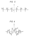
- Fig. 5 is a graph showing the impulse response of inverse filter.
- 51 is an impulse response of the inverse filter, representing the expression (4).
- the expression (4) must be truncated midway because it continues infinitely in the direction of x-axis. Therefore, it is desirable to use that function in the filtering processing after multiplication of the window function such as a hamming window.
- the Wiener filter can be substituted.
- the frequency characteristic of the Wiener filter R(f) can be represented in the following expression.
- R(f) H * ⁇ (f) H(x) 2 + ⁇ n (f)/ ⁇ s (f)
- ⁇ n(f) and ⁇ s (f) indicate the power spectrum of noise and image signal, respectively
- * ⁇ indicates the complex conjugate.
- ⁇ n (f) is set to be constant by assuming the white noise
- ⁇ s (f) is set to be the Gaussian type. Or they can be predetermined with the assumption that ⁇ n (f)/ ⁇ s (f) is constant over all frequencies.
- the value is almost the same as that of inverse filter, or conversely, it is close to zero at the frequency where the noise component is larger than the signal component.
- Fig. 6 is a graph showing the frequency characteristic of Wiener filter.
- 61 is a frequency characteristic of Wiener filter. Compared with the frequency characteristic 43 of inverse filter, it can be seen that the gain is smaller at the frequency area with the poor SN ratio. And in the Wiener filter, like the inverse filter, it is desirable that the characteristic may be adaptively change depending on the movement vector 24.
- Various filter characteristics of the filter 10 have generally the characteristic of a high-pass filter or band-pass filter.
- Fig. 7 is a block diagram showing a second embodiment of the present invention.
- the second embodiment shows a device which is effective when there are moving area and stationary area in an image, and further when the moving area is separated into a plurality of regions which have different movement vectors.
- 71 is an output of the movement amount detection circuit 7, i.e., the movement vector for each block or pixel within a screen.
- 72 is an area discrimination circuit
- 73 is its output, i.e., an address offset signal
- 74 and 75 are other outputs of the area discrimination circuit 72, i.e., the area signal and movement vector within area, respectively.
- 76 is a switch for sending the input signal to either of two output lines.
- 77 is an output video signal being processed for each area.
- the stages where the input image signal is converted from analog to digital form, stored into the frame memory 6, and transferred to the movement amount detection circuit 7 are the same as in the first embodiment.
- the movement amount detection circuit 7 transfers the movement vector 71 to the area discrimination circuit 72.
- the area discrimination circuit 72 divides the screen into the stationary area and a plurality of moving areas having different movement vectors, based on the movement vector 71.
- the area discrimination circuit 72 selects a desired area of divided areas, and sends the movement vector of the selected area as an address offset signal 73 to the memory reading circuit 8.
- the memory reading circuit 8 reads the image signal from the frame memory 6 by offsetting the address, based on the received signal. Thereby, the entire screen is shifted.
- the area discrimination circuit 72 sends the area signal 74 and the movement vector 75 within area to the parameter setting circuit 9, and the parameter setting circuit 9 sets the filter of different characteristic for each area to the filter 10.
- the area signal 74 is also sent to the switch 76, which sends the image signal from the frame memory 76 to the D/A converter 11 for the stationary area or to the filter 10 for the moving area.
- the output of filter 10 is subsequently sent to the D/A converter 11. That is, only for the moving area, the filtering processing is performed.
- the switch 76 can be integrated into the filter to by using a filter which allows the transmission of whole frequency band, if the stationary area is considered as a special case in the filter 10.
- the analog signal output of the D/A converter 11 has a synchronism signal added by the synchronism signal adding circuit 12, and sent out as the output video signal 77 being processed for each area.
- Fig. 8 is a plan view showing images containing a plurality of movements.
- 81 is an output screen which corresponds to a monitor display screen.
- 82 and 83 are first and second images of previous screen, respectively.
- 84 and 85 are first and second images of current screen, respectively.
- 86 is a background image, composed of small squares arranged in Fig. 8.
- the first and second images 82, 83 of previous screen are moved to the first and second images 84, 85 of current screen on the output screen 81, respectively.
- the background image 86 is not moved herein, i.e., coincident between previous screen and current screen.
- Fig. 9 is a plan view showing the area discrimination result.
- 91 and 92 are first and second moving areas, respectively.
- 93 and 94 are the movement vectors within areas of the moving areas 91, 92.
- 95 is a stationary area.
- the area discrimination circuit 72 of Fig. 7 performs the area division and the calculation of movement vector within area as shown in Fig. 9. That is, the first and second moving areas 91, 92 and the stationary area 95 are divided, and the movement vectors 93, 94 within areas are obtained for the first and second moving areas 91, 92.
- the tracking of specified image is performed. If it is assumed that the second image 83 is tracked in the current screen, the area discrimination circuit 72 sends the movement vector 94 within area of the second moving area 92 to the memory reading circuit as an address offset signal 73. At this time, as a result of shifting of the image due to the offset applied in reading the image signal from the frame memory 6, the second image 84 of current screen is displayed on the same place as the first image 83 of previous screen on the output screen 81. The images of other areas are shifted.
- the switch 76 sends the image signal of the first and second moving areas 91, 92 to the filter 10, and that of the stationary area 95 directly to the D/A converter.
- the filter 10 has its filter set with different characteristic by the parameter setting circuit 9, depending on the movement vectors 93, 94 within areas, for the images of the first and second moving areas 91, 92, in order to perform the filtering processing.
- the settings of filter and parameters used in the filter 10 are the same as in the first embodiment.
- the movement detection device of the present embodiment can compensate for the degradation of image quality resulting from the movement of image with the filtering processing, so that there is an effect of increasing the resolution of output image with the movement correction device, thereby providing a high quality image.
- the filter characteristic useful for the filtering processing has such an effect that the image quality is made excellent, nearly optimal, by changing it adaptively based on the movement vector to be obtained especially for the movement correction, and without increasing the cost.
- a device of the passive type in which the focusing signal is obtained by taking the correlation of images picked up by a twin-lens optical system, or an automatic focus adjustment device of the active type in which the focusing is judged from a position of spot generated by the reflected light flux by emitting infrared light onto an object.
- a focus detection device in which the focus detection is performed by carrying out the image processing of image signal.
- the signal for detecting the focusing state is obtained from the image signal, whereby there is a feature that the focus detection is allowed irrespective of the distance from an object, without special element or circuit for making the infrared projection and with high precision, so that the development has been rapidly progressed.
- Figs. 16A-16B are views for explaining an embodiment of focus detection method with a conventional image processing, illustrating the intensity distribution for the edge portion of an object image in the unfocused and focused states, in which Fig. 16A shows the unfocused state and Fig. 16B shows the focused state.
- EO shows an intensity distribution of the edge portion for an object image in the unfocused state, with a gradualdistribution due to the unfocused condition and a large width of edge portion.
- EI shows an intensity distribution of the edge portion for an object image in the focusing state and at the same place as for the intensity distribution EO of unfocused edge portion. In the focusing state, it shows a narrow and steeply rising up edge.
- the width of edge portion for object image is detected, and the focusing and unfocusing are judged from its edge width. That is, the focusing can be judged by making use of the property of narrow edge width at the focusing.
- the edge intensity distribution EO in the unfocused state is a distribution of the edge portion detected from the image signal, where the edge width is represented by the following expression.
- l 1 d 1 /(dI 1 (x)/dx)
- d 1 indicates an intensity difference of edge portion.
- I 1 (x) is a function for representing the intensity distribution of edge in the unfocused state, whereby dI 1 (x)/dx indicates a slope of edge. This slope of edge can be used by taking the average of slopes of focusing in a range from a portion where edge rises up to a portion where it becomes flat again.
- the width of edge l 2 can be calculated from the intensity distribution EI for the focusing, using the following expression.
- l 2 d 2 /(dI 2 (x)/dx)
- I 2 (x) is a function for representing the intensity distribution El of edge at the focusing
- dI 2 (x)/dx is a slope of edge.
- d 2 has almost the same value as d 1 , and dI 2 (x)/dx is larger than dI 1 (x)/dx.
- a method in which the edge width is calculated from a density difference and a slope of edge portion, and the state is judged nearer to the focusing if the value is smaller is practiced as one method of making the focus detection with the image processing.
- This embodiment has been made to resolve the above-mentioned problems, and is characterized by focus detection apparatus comprising movement detection means for detecting a movement of an image from the pick-up signal, movement correction means for correcting the movement of the image based on the output of the detection means, and focus detection means for performing the focus detection by extracting a signal component varying with the focusing state from the pick-up signal having its movement component of image corrected by the movement correction means.
- a high precision focus detection apparatus can be realized without decreasing its precision owing to the movement of image, in which the focus detection can be performed by detecting the movement of an image from an image signal, and using the signal for which the degradation of resolution due to the movement of the image is compensated.
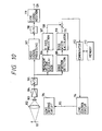
- Fig. 10 is a block diagram showing a third example of the present invention in which a movement detection device is applied to the focus detection apparatus.
- 101 is an object
- 102 is a pick-up lens
- 103 is a pick-up element or pick-up tube such as CCD for outputting a pick-up signal by photoelectrically converting an object image formed on a pick-up plane by the pick-up lens 2.
- 104 is an amplifier for amplifying the pick-up signal output from the pick-up element 3 to a predetermined level
- 105 is an A/D converter for converting an input analog pick-up signal to the digital signal
- 106 is a movement vector calculation circuit for obtaining the movement vector of image from the image signal which has been converted to the digital signal by the A/D converter 105
- 107 is an x-axis projection circuit for projecting the movement vector on the x-axis that is a horizontal direction of screen
- 108 is an x component of the movement vector.
- 109 is an edge detection circuit for detecting the edge portion for an object image
- 110 is an edge width detection circuit for detecting the width of edge portion detected by the edge detection circuit
- 111 is an edge width signal.
- 112 is a comparator, and 113 is a memory.
- 114 is a lens control circuit, 115 is an lens control signal, and 116 is a lens driving circuit for moving the pick-up lens 102 in a direction of optical axis to adjust the focus.
- 117 is a video signal processing circuit for outputting a standard television signal on television camera by performing the signal processing such as the gamma correction or various filtering to the pick-up signal output from the A/D converter 105
- 118 is a D/A converter for converting the digital signal output by the video signal processing circuit 117 to the analog signal
- 119 is a synchronism signal adding circuit for adding a synchronism signal to the image signal output from the D/A converter 118
- 120 is an output video signal.
- the pick-up lens 102 forms an image of object 101 on the pick-up plane of pick-up element 103, and the pick-up element 103 converts photoelectrically the image of object to output an image signal.
- the image formed on the pick-up element 103 involves the movement owing to the movement of the pick-up lens 102, pick-up element 103 or object 101.
- the image signal output from the pick-up element 103 is amplified by the amplifier 104, and converted to the digital signal by the A/D converter 105.
- the movement vector operation circuit 106 contains a frame memory where image of previous frame is stored, and in which the movement vector of image is calculated by comparing the image of current frame with that of previous frame stored in the frame memory.
- Exemplary of the method of operating the movement vector is that used in as a so-called representative point matching method or gradient method can be used.
- the x-axis projection circuit 107 gives an x-axis component signal 108 from the movement vector obtained by the movement vector operation circuit 106.
- the digitized image signal is sent to an edge portion detection circuit 109.
- the edge portion detection circuit 109 detects an edge portion from the information such as a slope for the image signal, and selects an edge having the largest slope with respect to the x-axis, for example, as the edge for judgement of the focusing.
- the edge width operation circuit 110 calculates the width of edge from a density difference of edge and a slope of edge, as above described, and output it as an edge width signal 111.
- the x-axis component signal 108 of movement vector is subtracted from the edge width signal 111 in subtractor 126, and the result is then sent to the comparator 112.
- the signal sent to the comparator 112 is an edge width signal with the movement of image corrected.
- the comparator 112 compares the corrected edge width signal input to it with data within the memory 113.
- the corrected edge width signal in previous field or frame is stored.
- the comparator 112 sends a control signal to the lens control circuit, as well as writing the smaller edge width signal of two corrected edge width signals into the memory 113.
- the control signal is one in which driving of the current pick-up lens 102 is continued in the same direction when a newly input edge width signal is smaller than the previous edge width signal, or driving is performed in a reverse direction when it is larger than the previous edge width signal. Also, it may be permitted to send a signal in which the amount of driving the lens is gradually changed depending on the amount of variation in the corrected edge signal. Or when the amount of variation is quite small, a control signal for stopping the amount of driving the lens can be sent by deciding the focusing state if the amount of variation is changed from negative to positive. In order to make the fine control, it is desirable that the corrected edge signals as much as several frames should be stored in the memory 113.
- the lens control circuit 14 issues a lens driving signal 115, based on a control signal sent from the comparator 112, in accordance with which the lens driving circuit 116 drives the pick-up lens 102.
- the digitized image signal is input into the video signal processing circuit 117, then input into the D/A converter 118 for conversion into the analog signal, has a synchronism signal added in the synchronism signal adding circuit 119, and output as a video signal.
- Fig. 11 is a view showing schematically the movement of image, like in Fig. 2.
- 121 is an output screen.
- 112 is a previous image
- 123 is a current image
- 124 is a movement vector when the previous image 122 moves to the current image 123.
- 125 is a projection vector of the movement vector 124 onto the x-axis.
- a video signal 120 of Fig. 10 is displayed.
- an image displayed with trembling of hand or panning shows the movement from previous image 122 to current image 123 when time has passed from one clock to another even if the object 101 is a stationary object.
- the movement vector 124 is operated in the movement vector operation circuit 106, and the projection vector 125 is calculated in the x-axis projection circuit and output as an x-axis signal component 108.
- current image 123 involves the movement
- the value of each pixel is integrated in the direction of movement vector 124. Accordingly, in practice, current image 123 as shown in Fig. 11 only shows approximately a gravitational center position of sides of each pattern.
- Fig. 12 is a front view showing the movement of optical system.
- 131 is one cell when the pick-up element is a solid pick-up element such as CCD.
- the pick-up element 103 converts a pattern of optical image thereon photoelectrically during a predetermined period of exposure.
- 132 is an optical image at the start of exposure
- 133 is an optical image at the termination of exposure.
- the optical image 132 at the start of exposure has been moved to the optical image 133 at the termination of exposure because image moves during exposure like in Fig. 11.
- the movement vector 124 as shown in Fig. 12 indicates the movement between the optical image 132 at the start of exposure and the optical image 133 at the termination of exposure. This is almost the same as in Fig. 11, but more strictly, slightly different.
- the movement vector as shown in Fig. 11 is one taken at nearly intermediate times of respective exposure periods for two images.
- the movement vector as shown in Fig. 12 is one taken for an image of interest from the start of exposure to the termination of exposure.
- both the movement vectors may have different values.
- both values can be almost the same, but the movement vector 124can be used after slight correction, because the movement vector 124 obtained from the movement vector operation circuit 106 is as shown in Fig. 11.
- Fig. 13 is a characteristic graph showing a point image distribution function with the movement of image.
- the form of function is the same as the example of Fig. 4.
- 141 is a point image distribution function.
- the length of projection vector 125 is c.
- the line generated by one point of object 102 moves during exposure period, approximately following the point image distribution function 141.
- h(x) Rect(x/c)
- the pick-up image becomes unfocused in accordance with the expression (1), due to its movement as well as the out-of-focus state.
- Fig. 14 is a characteristic graph showing the correction of edge width.
- 151 is an image signal of edge portion, with its intensity distribution being I(x). This corresponds to a signal directly obtained from the pick-up element 103.
- 152 is an intensity distribusion of edge portion when image does not contain any movement, its intensity distribution being I'(x). The gradualness of the edge for I'(x) can be determined by the shape of an original object and the amount of out-of-focus.
- the image signal 151 for edge portion is an image signal of portion selected in the edge portion detection circuit 109.
- I(x) I'(X)*h(x)
- ⁇ represents the convolution operation
- the width of edge l directly obtained from the image signal 151 of edge portion contains the size c of projection vector 125, thus having a larger value than originally obtained, and may vary in accordance with the movement of image.
- c the size of projection vector 125
- the movement vector is also projected onto the x-axis.
- the movement vector 124 is obtained in the form of representation with x-axis and y-axis components, the processing for the x-axis projection is practically unnecessary.
- the intensity distribution of edge portion is obtained in a horizontal axis, i.e., other than x-axis, for example, in the steepest direction of edge portion of interest, so as to operate the width of edge, the projection of movement vector is necessary.
- the size of projection vector can be obtained in a simple manner as a value of inner product between a unit vector in its direction and the movement vector.
- Fig. 15 is a block diagram showing a fourth example of focus detection apparatus according to the present invention.
- 161 is a frame memory
- 162 is a filter
- 163 is a parameter setting circuit for supplying parameters to the filter 162.
- 164 is an image signal filtered.
- the signal read from the pick-up element 103 is passed to the filtering processing based on the movement vector, to perform the focus detection from that signal.
- the digitized image signal is output from the A/D converter 105.
- the frame memory 161 stores this signal temporarily.
- the digitized image signal is also sent to the movement vector operation circuit 106, where the movement vector 124 is operated.
- the frame memory 161 acts as a delay element for synchronizing the image signal to terminate the operation of movement vector 124.
- the signal read from the frame memory 161 is sent to the filter 162, where the filtering processing is performed.
- the frequency characteristic of filter 162 is set by the parameter setting circuit 163, where the parameters are given to the filter 162 so as to correct unfocused image due to the movement from'the operation result of movement vector 124.
- the image signal 164 filtered is sent to the edge portion detection circuit 109, where like in the first embodiment, the edge portion is selected, and after that portion, the focusing judgment operation is performed to drive the pick-up lens 102.
- the image signal 164 filtered is sent to the video signal processing circuit 117, where like in the third embodiment, it is finally output as an output video signal 120.
- the filter for the filtering can use the characteristic as shown in Figs. 4B and 4C in the first example.
- Explaining this using Figs. 4B and 4C, 42 is a frequency characteristic showing the degradation of image with the movement, and can be represented by the previous expression (2).
- the inverse filter can be achieved only approximately, because it becomes infinite at the frequency where H(f) is zero.
- the range of frequency can be a range where the frequency spectrum for image signal exists.
- the characteristic of degradation H(f) and the characteristic of compensation filter P(f) contain the size a of movement vector 24 as the parameter.
- the x'-axis and f-axis are taken along the direction of movement vector 124, respectively, and P(f) depends on the size and direction of movement vector 124.
- the filter 162 changes adaptively the filter in accordance with the movement vector 124.
- Another method is the filtering on the axis of time, performed in such a way that the impulse response is obtained by the inverse Fourier transform of inverse filter P(f), and convoluted to image signal from the frame memory 6 so that filtered output can be obtained.
- the inverse filter and Wiener filter can be used, as described using expressions (10), (11) and Figs. 5, 6 in the previous first embodiment, and the explanation of analysis is omitted.
- the filtering With the filtering, the degradation of image, i.e., the degradation of resolution, can be compensated, so that the excellent focus detection can be made.
- the filter 162 other various filters are used.
- the filter characteristic of filter 162 has generally a characteristic of high-pass filter or band-pass filter.
- edge portion of edge signal 164 in the image signal 164 filtered is represented as a signal analogous to that as shown in Fig. 14. That is, before filtering, it is like the image signal 151 of edge portion, but after filtering, it becomes the intensity distribution 152 when there is no movement of image.
- edge width obtained is smaller than if the edge width is operated without taking into consideration the movement of image.
- the output video signal 120 itself can provide an excellent and high-quality image with high resolution.
- the method of operating the image signal was described, but when the service condition of pick-up device is much subject to the vibration, and provided with a vibration-proofing apparatus, the movement vector signal can be obtained from an angular sensor or acceleration sensor of vibration-proof apparatus. In this case, it is not simple to deal with the movement of object, but when the movement of whole screen is predominant due to the vibration, a desired movement vector can be obtained and the excellent focus detection can be made.
- the focus detection can be performed by detecting a signal component varying with the focusing state from the pick-up signal, wherein movement correction means is provided for detecting and correcting the movement of image, and particularly, the focus detection is made based on a signal component having the movement corrected by said movement detection means, so that it is possible to prevent the degradation of accuracy in the focus detection means caused by the decrease of signal depending on the focusing state, such as the gradualness at an edge portion or the decrease of high frequency component due to the movement of image, whereby a stable focus detection apparatus with high precision can be provided at all times in which it is not subject to the influence of camera vibration or the movement of object.
Landscapes
- Engineering & Computer Science (AREA)
- Multimedia (AREA)
- Signal Processing (AREA)
- Physics & Mathematics (AREA)
- General Physics & Mathematics (AREA)
- Optics & Photonics (AREA)
- Automatic Focus Adjustment (AREA)
Description
- The present invention relates to a movement detection device suitable for use with a vibration-proof device for compensating for the movement of image being picked-up by the camera due to trembling of hand or other vibrations, an automatic tracking apparatus for tracking a moving object, and an automatic focus detection apparatus for detecting the focusing state from a pick-up signal.
- Recently, image instruments such as a video camera or electronic camera have been remarkably developed in which to enable a more reliable and appropriate photographing operation, a movement correction device has been adopted, which allows the photographing of higher quality image without fluctuation by correcting the movement of image due to trembling of hand or other vibrations.
- The movement correction method for the movement correction device involves a mechanical correction method of using the inertia maintaining the axes of lens and image sensor fixed for the rotation of camera body, an optical correction method of using the optical member such as a variable apex angle prism, and an image processing correction method for making the correction by moving a screen with the image processing.
- According to the mechanical correction method, a special structure for supporting the lens and a pick-up system is required, and according to the optical correction method, a special optical member such as variable apex prism as described is required, while in the image processing correction method, no special mechanical structure and optical members are necessary, in which it has a feature of enabling the movement correction only with the signal processing in the electrical circuit, and is expected to be widely used in the future.
- However, the movement correction device with the above-mentioned conventional image processing method has a following disadvantage, compared with the mechanical or optical device.
- That is, in performing the movement correction with the image processing method, an image has some movement at the pick-up stage with an image sensor or pick-up tube, whereby in the post-processinq, the movement of image between fields or frames is removed by shifting the image in accordance with the amount of image movement.
- Thus, as the image obtained in the pick-up stage contains some blurring, the final resolution of the image is low even if the image movement is corrected in the post-processing, so that a poor quality of image results.
- Recently, in video instruments such as a video camera or electronic camera, an automatic focusing adjustment apparatus for adjusting the focus by detecting the state of focus from a pick-up signal has been adopted, but as above described, image movement may reduce a high spatial frequency component which varies with the state of focus of the pick-up signal, thereby decreasing image sharpness, and degrading the performance of automatic focusing adjustment apparatus, whereby there is a risk of malfunction and so it would be advantageous to detect and correct for the movement of image in the auto-focus processing using the pick-up signal.
- US-A-4612575 proposes a blur minimisation technique for the image from a video camera on a remote pilotless vehicle. Rate gyros provide measures of camera motion, and these are used to compute Wiener filter characteristics for filtering the image signal to remove blur.
- According to the present invention there is provided image processing apparatus as set out in
claim 1 and a method of processing an image signal as set out inclaim 13. Optional features are set out in the remaining claims. - The illustrated embodiments of the present invention provide a movement detection device which can compensate for the degradation of resolution due to movement of the image.
- An embodiment of the present invention provides a high quality image by compensating for the degradation of image quality resulting from image movement by means of filtering, and increasing the resolution of an output image for a movement correction device.
- Preferably the filter characteristics used in the filtering processing, are changed adaptively, preferably based on a movement vector to be obtained for the correction of movement.
- An embodiment of the present invention provides a stable focus detection apparatus with high precision, which is not subject to the influence of camera vibration or object movement because it is possible to prevent the degradation of accuracy in a focus detection means caused by a signal becoming less representative of the state of focus, e.g. due to unclearness of an edge portion or decrease of the high frequency component owing to the movement of the image.
- An embodiment is provided which is capable of making a high precision focus detection while avoiding the decrease of accuracy due to the movement of image, wherein the image movement is detected and the focus detection is made using a signal for which the degradation of resolution with the movement of the image has been compensated.
- Fig. 1 is a block diagram showing a first example of a movement detection device according to the present invention.
- Fig. 2 is a view showing the movement of image.
- Fig. 3 is a view showing the movement of optical image.
- Figs. 4A to 4C are characteristic views showing the filter characteristic for filtering.
- Fig. 5 is a characteristic view showing the inverse filter characteristic.
- Fig. 6 is a characteristic view showing the Wiener filter characteristic.
- Fig. 7 is a block diagram showing a second example of the present invention.
- Fig. 8 is a view showing images containing a plurality of movements.
- Fig. 9 is a view showing area decision results.
- Fig. 10 is a block diagram showing a third example of a movement correction device according to the present invention.
- Fig. 11 is a view showing the movement of image.
- Fig. 12 is a view showing the movement of optical system.
- Fig. 13 is a view showing a point image distribution function with the movement of image.
- Fig. 14 is a view showing the correction of edge width.
- Fig. 15 is a block diagram showing a fourth example of the present invention.
- Figs. 16A and 16B are schematic graphs showing a focus detection method with a conventional image processing.
- An embodiment of a movement correction device according to the present invention will be described in detail with reference to the drawings.
- Fig. 1 is a block diagram showing a first embodiment of movement correction device according to the present invention.
- In this figure, 1 is an object, 2 is a pick-up lens, and 3 is a pick-up element or pick-up tube such as CCD for outputting a pick-up signal by photoelectrically converting an object image formed on a pick-up plane by the pick-
up lens 2. 4 is an amplifier for amplifying the pick-up signal output from the pick-up element 3 to a predetermined level, 5 is an A/D converter for converting the input analog pick-up signal to the digital signal, 6 is a frame memory for storing the image signal converted into the digital signal by the A/D converter 5, and 7 is a movement amount detection circuit for obtaining a movement vector from the image signal which has been converted from analog to digital form. Exemplary of a method of calculating the movement vector is that as used in a so-called representative point matching method or gradient method. 8 is a memory reading circuit for reading an image signal from theframe memory 6 by generating a read address and executing the reading. - 9 is a parameter setting circuit for setting parameters for prevention of image degradation, and 10 is a filter.
- 11 is a D/A converter for converting the digital image signal passing through the
filter 10 to the analog image signal, 12 is a synchronism signal adding circuit for adding a synchronism signal to the image signal, and 13 is an output video signal. - The pick-
up lens 2 forms an image ofobject 1 on the pick-up plane of pick-up element 3. The image on the pick-up element 3 involves the movement owing to the movement of thelens 2, pick-up element 3 orobject 1. The image signal output from the pick-up element 3 is amplified by theamplifier 4, converted to the digital signal by the A/D converter 5, and then stored in theframe memory 6 temporarily. - The digital image signal which is an output of A/
D converter 5 is also transferred to the movement amount detection circuit 7. Movement vector data obtained by the movement amount detection circuit 7 are transferred to thememory reading circuit 8 and theparameter setting circuit 9. - The movement detection circuit 7 requires data of screen one frame or field before the current screen for calculating the amount of movement, thereby requiring a frame memory. This frame memory may be constructed in common with the
frame memory 6, or separately provided. - The
memory reading circuit 8 creates the address for reading theframe memory 6 modified by the offset based on movement vector data. Thereby, data read from theframe memory 6 are read out in such a way so as to move data almost reversely to the movement of image, so that the movement of image can be corrected. That is, the correction of image deflection can be achieved on the memory. - The
parameter setting circuit 9 determines parameters such as filter coefficients based on the movement vector obtained from the movement amount detection circuit 7, and sends them to thefilter 10. Thefilter 10 filters the image signal having corrected movement read from theframe memory 6, so as to reduce the unfocused part resulting from the movement of image on the pick-up element 3, i.e., the degradation of resolution. - Also, the
filter 10 has the characteristics of a high-pass filter and a band-pass filter as will be described later. - The image signal output from the
filter 10 is converted to the analog signal by the D/A converter 11, synthesized with a synchronism signal by the synchronismsignal adding circuit 12, and output as thevideo signal 13. - The improvement of resolution with the filtering will be described in the following.
- Fig. 2 is a plan view showing the movement of image.
- 21 is an output screen. The
output screen 21 has a fixed coordinate system which is useful for the reference to perform the processing such as the vibration isolation. Here, a monitor display screen can be assumed, for example. - 22 is a previous image, and 23 is a current image. 24 is a movement vector when the
previous image 22 moves to thecurrent image 23. - In the
output screen 21, avideo signal 13 of Fig. 1 is displayed. For example, an image displayed with trembling of hand shows the movement fromprevious image 22 tocurrent image 23 if time has passed from one clock to another when theobject 1 is stationary. - With the movement correction method in the image processing, the movement correction is performed in such a manner that the
movement vector 24 is calculated in the movement amount detection circuit 7, data is shifted by the amount ofmovement vector 24 on theoutput screen 21 when data ofcurrent image 23 is read from theframe memory 6, and the offset is added to the read address so thatcurrent image 23 can be superimposed almost onprevious image 22. - As
current image 23 includes movement, the value of each pixel integrates image points in a direction ofmovement vector 24. Accordingly, in practice, thecurrent image 23 of Fig. 2 only shows approximately a gravitational center position of the sides of each pattern. - Fig. 3 is a front view showing the movement of optical system. In the same figure, 31 is one cell when the pick-up element is a solid pick-up element such as CCD. For the convenience of explanation, it is assumed that the movement direction of image coincides with a direction of array for one cell in the pick-up
element 3. The pick-upelement 3 converts a pattern of optical image thereon photoelectrically during a predetermined period of exposure. 32 is an optical image at the start of exposure, and 33 is an optical image at the termination of exposure. Theoptical image 32 at the start of exposure is moved to theoptical image 33 at the termination of exposure because the image moves during exposure as shown in Fig. 2. - The
movement vector 24 as shown in Fig. 3 indicates the movement between theoptical image 32 at the start of exposure and theoptical image 33 at the termination of exposure. This is almost the same as that of Fig. 2, but more strictly, slightly different. That is, the movement vector as shown in Fig. 2 is one taken at nearly intermediate times of respective exposure periods for two images. On the contrary, the movement vector as shown in Fig. 3 is one taken for an image of interest from the start of exposure to the termination of exposure. Accordingly, when the amount of image movement changes abruptly, both movement vectors will have different values. Generally, both of the values can be almost the same, but themovement vector 24 as shown in Fig. 3 may be used after some slight correction when required in theparameter setting circuit 9, because themovement vector 24 obtained from the movement detection circuit 7 is one as shown in Fig. 2. - Figs. 4A-4C are graphs showing the filter characteristics for the filtering useful in the
filter 10 for correcting the degradation of image. - In Fig. 4A, 41 is a point image distribution function with the movement of image. The axis of abscissa x in the spatial coordinate system is taken along the movement direction. The length of the
movement vector 24 is assumed to be a. Then, the image generated by one point ofobject 1 moves during exposure period, approximately following the pointimage distribution function 41. - Representing that function as h(x),

- 42 in Fig. 4B is a frequency characteristic showing the degradation of image.
- Representing the frequency as f and the frequency characteristic 42 as H(f),

- 43 in Fig. 4C is a frequency characteristic of filter, and representing it as P(f),

- Such a filter is called as an inverse filter.
- That is, H(f)·P(f)=1, which means that the filtering of P(f) can compensate for the degradation of image with H(f).
- In the
filter 10 of Fig. 1, by filtering with this filter, the resolution ofoutput video signal 13 is enhanced and excellent quality of image can be obtained. However, the inverse filter can be realized only approximately because it has infinite value at the frequency where the Fourier transform H(f) is zero. And the frequency range can be a range where the frequency spectrum exists. - As clearly seen from Figs. 4A-4C and expressions (2), (3), the characteristic of degradation H(f) and the characteristic of compensation filter P(f) contain the size a of
movement vector 24 as a parameter. The x-axis and f-axis are each taken along the direction ofmovement vector 24, which reveals that P(f) depends on the size and direction ofmovement vector 24. - Accordingly, it is desirable that the
filter 10 has its filter changed adaptively depending on themovement vector 24. - The
filter 10 has two methods of performing the filtering processing. One of them is the filtering on the axis of frequency, in which the Fourier transform is taken of the image signal read out from theframe memory 6 with FFT (Fast Fourier Transform), which is then multiplied by the inverse filter P(f), and the inverse Fourier transform is taken so that filtered image signal is obtained. - Another method is the filtering on the axis of time, performed in such a way that the impulse response is obtained by the inverse Fourier transformation of inverse filter P(f), and convoluted to image signal from the
frame memory 6 so that filtered output can be obtained. - When the inverse filter is realized with the convolution in the axis of time, an impulse response S(x) of filter in the following expression can be used.


- Note that the expression (4) is obtained by taking the Fourier transform of expression (3) using the delta function.
- Fig. 5 is a graph showing the impulse response of inverse filter.
- 51 is an impulse response of the inverse filter, representing the expression (4).
- The expression (4) must be truncated midway because it continues infinitely in the direction of x-axis. Therefore, it is desirable to use that function in the filtering processing after multiplication of the window function such as a hamming window.
- In the inverse filter, the frequency area where the image information is almost lost with the degradation of image, i.e., where the value of frequency characteristic 42 is zero, and the high frequency area where there is only a few image information by nature may be given the characteristic of a large gain so that the output image has often a poor S/N ratio. Therefore, in the
filter 10, the Wiener filter can be substituted. - The frequency characteristic of the Wiener filter R(f) can be represented in the following expression.

- Here, as it is difficult to obtain Φn(f) and Φs(f) correctly, Φn(f) is set to be constant by assuming the white noise, and Φs(f) is set to be the Gaussian type. Or they can be predetermined with the assumption that Φn(f)/Φs(f) is constant over all frequencies.
- In the Wiener filter, at the frequency where the signal component is sufficiently larger than the noise component, the value is almost the same as that of inverse filter, or conversely, it is close to zero at the frequency where the noise component is larger than the signal component.
- Fig. 6 is a graph showing the frequency characteristic of Wiener filter. 61 is a frequency characteristic of Wiener filter. Compared with the
frequency characteristic 43 of inverse filter, it can be seen that the gain is smaller at the frequency area with the poor SN ratio. And in the Wiener filter, like the inverse filter, it is desirable that the characteristic may be adaptively change depending on themovement vector 24. - Various filter characteristics of the
filter 10 have generally the characteristic of a high-pass filter or band-pass filter. - Fig. 7 is a block diagram showing a second embodiment of the present invention.
- The second embodiment shows a device which is effective when there are moving area and stationary area in an image, and further when the moving area is separated into a plurality of regions which have different movement vectors.
- 71 is an output of the movement amount detection circuit 7, i.e., the movement vector for each block or pixel within a screen. 72 is an area discrimination circuit, 73 is its output, i.e., an address offset signal, 74 and 75 are other outputs of the area discrimination circuit 72, i.e., the area signal and movement vector within area, respectively. 76 is a switch for sending the input signal to either of two output lines. 77 is an output video signal being processed for each area.
- The stages where the input image signal is converted from analog to digital form, stored into the
frame memory 6, and transferred to the movement amount detection circuit 7 are the same as in the first embodiment. - The movement amount detection circuit 7 transfers the
movement vector 71 to the area discrimination circuit 72. - The area discrimination circuit 72 divides the screen into the stationary area and a plurality of moving areas having different movement vectors, based on the
movement vector 71. The area discrimination circuit 72 selects a desired area of divided areas, and sends the movement vector of the selected area as an address offset signal 73 to thememory reading circuit 8. Thememory reading circuit 8 reads the image signal from theframe memory 6 by offsetting the address, based on the received signal. Thereby, the entire screen is shifted. - The area discrimination circuit 72 sends the
area signal 74 and themovement vector 75 within area to theparameter setting circuit 9, and theparameter setting circuit 9 sets the filter of different characteristic for each area to thefilter 10. Thearea signal 74 is also sent to theswitch 76, which sends the image signal from theframe memory 76 to the D/A converter 11 for the stationary area or to thefilter 10 for the moving area. The output offilter 10 is subsequently sent to the D/A converter 11. That is, only for the moving area, the filtering processing is performed. - Note that the
switch 76 can be integrated into the filter to by using a filter which allows the transmission of whole frequency band, if the stationary area is considered as a special case in thefilter 10. - The analog signal output of the D/
A converter 11 has a synchronism signal added by the synchronismsignal adding circuit 12, and sent out as theoutput video signal 77 being processed for each area. - Fig. 8 is a plan view showing images containing a plurality of movements.
- In this figure, 81 is an output screen which corresponds to a monitor display screen.
- 82 and 83 are first and second images of previous screen, respectively. 84 and 85 are first and second images of current screen, respectively. 86 is a background image, composed of small squares arranged in Fig. 8.
- In transferring from previous screen to current screen, the first and
second images second images output screen 81, respectively. However, the moving directions and sizes of two images are different. Thebackground image 86 is not moved herein, i.e., coincident between previous screen and current screen. - Fig. 9 is a plan view showing the area discrimination result.
- 91 and 92 are first and second moving areas, respectively. 93 and 94 are the movement vectors within areas of the moving
areas - The area discrimination circuit 72 of Fig. 7 performs the area division and the calculation of movement vector within area as shown in Fig. 9. That is, the first and second moving
areas stationary area 95 are divided, and themovement vectors areas - When the device as shown in Fig. 7 is a tracking device, the tracking of specified image is performed. If it is assumed that the
second image 83 is tracked in the current screen, the area discrimination circuit 72 sends themovement vector 94 within area of the second movingarea 92 to the memory reading circuit as an address offset signal 73. At this time, as a result of shifting of the image due to the offset applied in reading the image signal from theframe memory 6, thesecond image 84 of current screen is displayed on the same place as thefirst image 83 of previous screen on theoutput screen 81. The images of other areas are shifted. - The
switch 76 sends the image signal of the first and second movingareas filter 10, and that of thestationary area 95 directly to the D/A converter. - The
filter 10 has its filter set with different characteristic by theparameter setting circuit 9, depending on themovement vectors areas filter 10 are the same as in the first embodiment. - As above described, the movement detection device of the present embodiment can compensate for the degradation of image quality resulting from the movement of image with the filtering processing, so that there is an effect of increasing the resolution of output image with the movement correction device, thereby providing a high quality image.
- Further, the filter characteristic useful for the filtering processing has such an effect that the image quality is made excellent, nearly optimal, by changing it adaptively based on the movement vector to be obtained especially for the movement correction, and without increasing the cost.
- Next an embodiment in which the movement detection device is applied to a focus detection apparatus to improve the focus detection accuracy will be described.
- Recently, image equipments such as a video camera or electronic camera have been remarkably developed, and it is requisite for its function to have an automatic focus adjustment device in the respect of operativity.
- For implementing the focus detection device, there may be provided a device of the passive type in which the focusing signal is obtained by taking the correlation of images picked up by a twin-lens optical system, or an automatic focus adjustment device of the active type in which the focusing is judged from a position of spot generated by the reflected light flux by emitting infrared light onto an object.
- On the other hand, in the pick-up device such as a television camera for obtaining the image signal, a focus detection device has been developed in which the focus detection is performed by carrying out the image processing of image signal. In such device using the image processing, the signal for detecting the focusing state is obtained from the image signal, whereby there is a feature that the focus detection is allowed irrespective of the distance from an object, without special element or circuit for making the infrared projection and with high precision, so that the development has been rapidly progressed.
- Figs. 16A-16B are views for explaining an embodiment of focus detection method with a conventional image processing, illustrating the intensity distribution for the edge portion of an object image in the unfocused and focused states, in which Fig. 16A shows the unfocused state and Fig. 16B shows the focused state.
- In Fig. 16A, EO shows an intensity distribution of the edge portion for an object image in the unfocused state, with a gradualdistribution due to the unfocused condition and a large width of edge portion.
- Also, in Fig. 16B, EI shows an intensity distribution of the edge portion for an object image in the focusing state and at the same place as for the intensity distribution EO of unfocused edge portion. In the focusing state, it shows a narrow and steeply rising up edge.
- Accordingly, the width of edge portion for object image is detected, and the focusing and unfocusing are judged from its edge width. That is, the focusing can be judged by making use of the property of narrow edge width at the focusing.
- The edge intensity distribution EO in the unfocused state is a distribution of the edge portion detected from the image signal, where the edge width is represented by the following expression.

- Also, at the focusing, the width of edge ℓ2 can be calculated from the intensity distribution EI for the focusing, using the following expression.

- Accordingly, since ℓ2 is a smaller value than ℓ1, it can be seen that the edge width becomes smaller and the focusing has been adjusted.
- In this way, generally, a method in which the edge width is calculated from a density difference and a slope of edge portion, and the state is judged nearer to the focusing if the value is smaller is practiced as one method of making the focus detection with the image processing.
- However, in the above-mentioned focus detection device, when an image has the movement, i.e., when an object is moving, or when the whole screen has shifted as a result of trembling of hand and panning, the image becomes blurred due to its movement, whereby there is a disadvantage that the width of edge is widened due to the movement, and correct detection of focus can not be made.
- This embodiment has been made to resolve the above-mentioned problems, and is characterized by focus detection apparatus comprising movement detection means for detecting a movement of an image from the pick-up signal, movement correction means for correcting the movement of the image based on the output of the detection means, and focus detection means for performing the focus detection by extracting a signal component varying with the focusing state from the pick-up signal having its movement component of image corrected by the movement correction means.
- Thereby, a high precision focus detection apparatus can be realized without decreasing its precision owing to the movement of image, in which the focus detection can be performed by detecting the movement of an image from an image signal, and using the signal for which the degradation of resolution due to the movement of the image is compensated.
- A focus detection apparatus of this example will be described in detail with reference to the drawings.
- Fig. 10 is a block diagram showing a third example of the present invention in which a movement detection device is applied to the focus detection apparatus.
- In the same figure, 101 is an object, 102 is a pick-up lens, and 103 is a pick-up element or pick-up tube such as CCD for outputting a pick-up signal by photoelectrically converting an object image formed on a pick-up plane by the pick-up
lens 2. 104 is an amplifier for amplifying the pick-up signal output from the pick-upelement 3 to a predetermined level, 105 is an A/D converter for converting an input analog pick-up signal to the digital signal, 106 is a movement vector calculation circuit for obtaining the movement vector of image from the image signal which has been converted to the digital signal by the A/D converter - 109 is an edge detection circuit for detecting the edge portion for an object image, 110 is an edge width detection circuit for detecting the width of edge portion detected by the
edge detection circuit - 112 is a comparator, and 113 is a memory. 114 is a lens control circuit, 115 is an lens control signal, and 116 is a lens driving circuit for moving the pick-up
lens 102 in a direction of optical axis to adjust the focus. - On the other hand, 117 is a video signal processing circuit for outputting a standard television signal on television camera by performing the signal processing such as the gamma correction or various filtering to the pick-up signal output from the A/
D converter signal processing circuit 117 to the analog signal, and 119 is a synchronism signal adding circuit for adding a synchronism signal to the image signal output from the D/A converter - With the above constitution, the pick-up
lens 102 forms an image ofobject 101 on the pick-up plane of pick-upelement 103, and the pick-upelement 103 converts photoelectrically the image of object to output an image signal. The image formed on the pick-upelement 103 involves the movement owing to the movement of the pick-uplens 102, pick-upelement 103 orobject 101. - The image signal output from the pick-up
element 103 is amplified by theamplifier 104, and converted to the digital signal by the A/D converter 105. - A part of the digitized image signal is input into the movement
vector operation circuit 106. The movementvector operation circuit 106 contains a frame memory where image of previous frame is stored, and in which the movement vector of image is calculated by comparing the image of current frame with that of previous frame stored in the frame memory. Exemplary of the method of operating the movement vector is that used in as a so-called representative point matching method or gradient method can be used. - The
x-axis projection circuit 107 gives anx-axis component signal 108 from the movement vector obtained by the movementvector operation circuit 106. - The digitized image signal is sent to an edge
portion detection circuit 109. The edgeportion detection circuit 109 detects an edge portion from the information such as a slope for the image signal, and selects an edge having the largest slope with respect to the x-axis, for example, as the edge for judgement of the focusing. The edgewidth operation circuit 110 calculates the width of edge from a density difference of edge and a slope of edge, as above described, and output it as anedge width signal 111. Thex-axis component signal 108 of movement vector is subtracted from theedge width signal 111 in subtractor 126, and the result is then sent to thecomparator 112. The signal sent to thecomparator 112 is an edge width signal with the movement of image corrected. Thecomparator 112 compares the corrected edge width signal input to it with data within thememory 113. - Within the
memory 113, the corrected edge width signal in previous field or frame is stored. - The
comparator 112 sends a control signal to the lens control circuit, as well as writing the smaller edge width signal of two corrected edge width signals into thememory 113. - The control signal is one in which driving of the current pick-up
lens 102 is continued in the same direction when a newly input edge width signal is smaller than the previous edge width signal, or driving is performed in a reverse direction when it is larger than the previous edge width signal. Also, it may be permitted to send a signal in which the amount of driving the lens is gradually changed depending on the amount of variation in the corrected edge signal. Or when the amount of variation is quite small, a control signal for stopping the amount of driving the lens can be sent by deciding the focusing state if the amount of variation is changed from negative to positive. In order to make the fine control, it is desirable that the corrected edge signals as much as several frames should be stored in thememory 113. - The lens control circuit 14 issues a
lens driving signal 115, based on a control signal sent from thecomparator 112, in accordance with which thelens driving circuit 116 drives the pick-uplens 102. - On the other hand, the digitized image signal is input into the video
signal processing circuit 117, then input into the D/A converter 118 for conversion into the analog signal, has a synchronism signal added in the synchronismsignal adding circuit 119, and output as a video signal. - Fig. 11 is a view showing schematically the movement of image, like in Fig. 2.
- In this figure, 121 is an output screen. For example, a monitor display screen can be assumed. Like in Fig. 2, 112 is a previous image, and 123 is a current image. 124 is a movement vector when the
previous image 122 moves to thecurrent image 123. 125 is a projection vector of themovement vector 124 onto the x-axis. - In the
output screen 121, avideo signal 120 of Fig. 10 is displayed. - For example, an image displayed with trembling of hand or panning shows the movement from
previous image 122 tocurrent image 123 when time has passed from one clock to another even if theobject 101 is a stationary object. - Accordingly, the
movement vector 124 is operated in the movementvector operation circuit 106, and theprojection vector 125 is calculated in the x-axis projection circuit and output as anx-axis signal component 108. - Here, as the
current image 123 involves the movement, the value of each pixel is integrated in the direction ofmovement vector 124. Accordingly, in practice,current image 123 as shown in Fig. 11 only shows approximately a gravitational center position of sides of each pattern. - Fig. 12 is a front view showing the movement of optical system. In the same figure, 131 is one cell when the pick-up element is a solid pick-up element such as CCD.
- For the convenience of explanation, it is assumed that the movement direction of image coincides with the array direction of one cell in the pick-up
element 103. The pick-upelement 103 converts a pattern of optical image thereon photoelectrically during a predetermined period of exposure. 132 is an optical image at the start of exposure, and 133 is an optical image at the termination of exposure. Theoptical image 132 at the start of exposure has been moved to theoptical image 133 at the termination of exposure because image moves during exposure like in Fig. 11. Themovement vector 124 as shown in Fig. 12 indicates the movement between theoptical image 132 at the start of exposure and theoptical image 133 at the termination of exposure. This is almost the same as in Fig. 11, but more strictly, slightly different. - That is, the movement vector as shown in Fig. 11 is one taken at nearly intermediate times of respective exposure periods for two images. On the contrary, the movement vector as shown in Fig. 12 is one taken for an image of interest from the start of exposure to the termination of exposure.
- Accordingly, when the amount of image movement changes abruptly, both the movement vectors may have different values. Generally, both values can be almost the same, but the movement vector 124can be used after slight correction, because the
movement vector 124 obtained from the movementvector operation circuit 106 is as shown in Fig. 11. - Fig. 13 is a characteristic graph showing a point image distribution function with the movement of image. The form of function is the same as the example of Fig. 4. 141 is a point image distribution function. Here, it is assumed that the length of
projection vector 125 is c. Then, the line generated by one point ofobject 102 moves during exposure period, approximately following the pointimage distribution function 141. Representing that function as h(x) which can be represented as previously shown in the expression (1),
- Fig. 14 is a characteristic graph showing the correction of edge width.
- 151 is an image signal of edge portion, with its intensity distribution being I(x). This corresponds to a signal directly obtained from the pick-up
element 103. 152 is an intensity distribusion of edge portion when image does not contain any movement, its intensity distribution being I'(x). The gradualness of the edge for I'(x) can be determined by the shape of an original object and the amount of out-of-focus. - The
image signal 151 for edge portion is an image signal of portion selected in the edgeportion detection circuit 109. The edgewidth operation circuit 110 operates the width of edge ℓ from a density difference of edge d and a slope dI(x)/dx, such that
- Between I(x) and I'(x), the following relation stands.

- h(x) is a function of width c as shown in Fig. 13, in which I(x) has an edge slope portion widened by about c/2 to the right and left, compared with I'(x), as shown in Fig. 14. Accordingly, assuming the width of edge for I'(x) as I', the following expression approximately stands.

- The width of edge ℓ directly obtained from the
image signal 151 of edge portion contains the size c ofprojection vector 125, thus having a larger value than originally obtained, and may vary in accordance with the movement of image. In the expression (11), by subtracting c from ℓ, it is clear that ℓ' can be obtained, and is not subject to the influence of the movement of image by judging the focusing based on ℓ'. - That is, as shown in Fig. 10, by subtracting an
x-axis signal component 108 having the value of c from anedge width signal 111 having the value of ℓ, ℓ' is obtained, and then input into the comparator for use as a signal for judging the focusing, so that the detection of focusing can be made without influence of the movement of image. - In the explanation given herein, by considering that the intensity distribution of edge portion is obtained along the x-axis, the movement vector is also projected onto the x-axis. As the
movement vector 124 is obtained in the form of representation with x-axis and y-axis components, the processing for the x-axis projection is practically unnecessary. But if the intensity distribution of edge portion is obtained in a horizontal axis, i.e., other than x-axis, for example, in the steepest direction of edge portion of interest, so as to operate the width of edge, the projection of movement vector is necessary. The size of projection vector can be obtained in a simple manner as a value of inner product between a unit vector in its direction and the movement vector. - Fig. 15 is a block diagram showing a fourth example of focus detection apparatus according to the present invention.
- In the same figure, 161 is a frame memory, and 162 is a filter. 163 is a parameter setting circuit for supplying parameters to the
filter 162. 164 is an image signal filtered. - In this example, the signal read from the pick-up
element 103 is passed to the filtering processing based on the movement vector, to perform the focus detection from that signal. - Like in the third embodiment, the digitized image signal is output from the A/
D converter 105. Theframe memory 161 stores this signal temporarily. - The digitized image signal is also sent to the movement
vector operation circuit 106, where themovement vector 124 is operated. Theframe memory 161 acts as a delay element for synchronizing the image signal to terminate the operation ofmovement vector 124. - The signal read from the
frame memory 161 is sent to thefilter 162, where the filtering processing is performed. The frequency characteristic offilter 162 is set by theparameter setting circuit 163, where the parameters are given to thefilter 162 so as to correct unfocused image due to the movement from'the operation result ofmovement vector 124. - The
image signal 164 filtered is sent to the edgeportion detection circuit 109, where like in the first embodiment, the edge portion is selected, and after that portion, the focusing judgment operation is performed to drive the pick-uplens 102. - On the other hand, the
image signal 164 filtered is sent to the videosignal processing circuit 117, where like in the third embodiment, it is finally output as anoutput video signal 120. - The principle of this example will be described below.
- Let the size of
movement vector 124 be a', and let the spatial coordinate along the movement direction be x'. The point image distribution function h'(x) generated by themovement vector 24 is given by, in accordance with the previous expression (1),
- The filter for the filtering can use the characteristic as shown in Figs. 4B and 4C in the first example. Explaining this using Figs. 4B and 4C, 42 is a frequency characteristic showing the degradation of image with the movement, and can be represented by the previous expression (2).
- Accordingly, the frequency characteristic of inverse filter for compensating for the degradation of image as above described is as shown by 43 in Fig. 4C. That is, H(f)·P(F)=1, in which the filtering with P(f) allows the compensation for the degradation of image with H(f).
- By filtering with that filter in the
filter 162 in Fig. 15, the resolution ofoutput video signal 120 is increased, so that excellent image can be obtained. However, in this embodiment, the inverse filter can be achieved only approximately, because it becomes infinite at the frequency where H(f) is zero. The range of frequency can be a range where the frequency spectrum for image signal exists. - As clearly seen from Figs. 4A and 4C, expressions (2) and (3), the characteristic of degradation H(f) and the characteristic of compensation filter P(f) contain the size a of
movement vector 24 as the parameter. The x'-axis and f-axis are taken along the direction ofmovement vector 124, respectively, and P(f) depends on the size and direction ofmovement vector 124. - Accordingly, it is desirable that the
filter 162 changes adaptively the filter in accordance with themovement vector 124. - In order to perform the filtering processing in the
filter 162, there are two methods like in the previous first embodiment. One of them is the filtering on the axis of frequency, in which the Fourier transform is taken of the image signal read out from theframe memory 161 with FFT (Fast Fourier Transform), which is then multiplied by the inverse filter P(f), and the inverse Fourier transform is taken, so that filtered image signal is obtained. - Another method is the filtering on the axis of time, performed in such a way that the impulse response is obtained by the inverse Fourier transform of inverse filter P(f), and convoluted to image signal from the
frame memory 6 so that filtered output can be obtained. - As regards the constitution of filter and the filtering processing used herein, the inverse filter and Wiener filter can be used, as described using expressions (10), (11) and Figs. 5, 6 in the previous first embodiment, and the explanation of analysis is omitted. With the filtering, the degradation of image, i.e., the degradation of resolution, can be compensated, so that the excellent focus detection can be made.
- Also, in the
filter 162, other various filters are used. As the frequency characteristic 43 has a characteristic of low-pass filter, the filter characteristic offilter 162 has generally a characteristic of high-pass filter or band-pass filter. - As edge portion of
edge signal 164 in theimage signal 164 filtered is represented as a signal analogous to that as shown in Fig. 14. That is, before filtering, it is like theimage signal 151 of edge portion, but after filtering, it becomes theintensity distribution 152 when there is no movement of image. - Accordingly, by operating an edge signal width from the
image signal 164 filtered and using it for judgment of the focusing, stable detection of focus can be performed without almost any influence of image movement. Also in this case, the value of edge width obtained is smaller than if the edge width is operated without taking into consideration the movement of image. - Also, in this embodiment, there is a feature that the
output video signal 120 itself can provide an excellent and high-quality image with high resolution. - When the whole screen does not move and an object is moving, by dividing the area, portions having common movements can be subjected to the processing based on the same movement vector.
- It is noted that for the detection of image movement, the method of operating the image signal was described, but when the service condition of pick-up device is much subject to the vibration, and provided with a vibration-proofing apparatus, the movement vector signal can be obtained from an angular sensor or acceleration sensor of vibration-proof apparatus. In this case, it is not simple to deal with the movement of object, but when the movement of whole screen is predominant due to the vibration, a desired movement vector can be obtained and the excellent focus detection can be made.
- As above described, with the focus detection apparatus embodying the present invention, the focus detection can be performed by detecting a signal component varying with the focusing state from the pick-up signal, wherein movement correction means is provided for detecting and correcting the movement of image, and particularly, the focus detection is made based on a signal component having the movement corrected by said movement detection means, so that it is possible to prevent the degradation of accuracy in the focus detection means caused by the decrease of signal depending on the focusing state, such as the gradualness at an edge portion or the decrease of high frequency component due to the movement of image, whereby a stable focus detection apparatus with high precision can be provided at all times in which it is not subject to the influence of camera vibration or the movement of object.
Claims (22)
- Image processing apparatus for processing an image signal output from an image pick-up means (3) in fields or frames, the apparatus comprising:motion detection means (7) for detecting movement in the image represented by the image signal;motion compensation means (6, 8) for compensating the image signal for differences from one field or frame to another resulting from movement in the image, the motion compensation means comprising an image memory (6) and means (8) for reading the image from the image memory with a shift determined in dependence on the amount and direction of image movement detected by the motion detection means,characterised by filter means (9, 10) for filtering the image signal to compensate for the reduction in resolution within a field or frame of the image signal resulting from movement of the image, by high pass or band pass filtering and setting the filter characteristic of the filter means in response to the movement in the image detected by the motion detection means.
- Apparatus according to claim 1 in which the filter means comprises an inverse filter having a spatial frequency characteristic for correcting a spatial frequency characteristic of the movement in the image.
- Apparatus according to claim 1 in which the filter means comprises a Wiener filter.
- Apparatus according to any one of the preceding claims in which the motion detection means (7) detects movement in the image from the image signal.
- Apparatus according to any one of the preceding claims in which the means (8) for reading the image comprises means for generating addresses for reading the image based on the said amount and direction of image movement.
- Apparatus according to any one of the preceding claims in which the filter means is provided on the output side of the image memory.
- Apparatus according to any one of the preceding claims in which the same signal from the motion detection means (7) representing movement in the image is input to the motion compensation means (6, 8) and to the filter means (9, 10).
- Apparatus according to any one of the preceding claims which comprises area discriminating means (72) for discriminating between different areas of the image which move differently and for controlling the filter means (9, 10) to treat the different areas differently.
- Apparatus according to claim 8 in which the filter means comprises switch means (76), controlled by the area discriminating means, for selectively passing the image signal to be filtered or to be output without filtering.
- Apparatus according to claim 8 in which the filter means is controllable by the area discriminating means selectively to act as a whole frequency band transmission filter for part of the image signal.
- Apparatus according to any one of the preceding claims comprising focus detection means (109, 110) for detecting, from the image signal, a measure of focus in the image, the focus detection means receiving the image signal after it has been compensated by the motion compensation means and the filter means.
- Apparatus according to claim 11 which comprises means (112, 113, 114) for adjusting the focusing state of a lens in response to the measure of focus in the image.
- A method of processing an image signal output from an image pick-up means (3) in fields or frames, comprising:detecting movement in the image represented by the image signal;compensating the image signal for differences from one field or frame to another resulting from movement of the image, by reading the image signal from a memory (6) with a shift determined in dependence on the amount and direction of image movement detected in the detecting step,characterised by
filtering the image signal to compensate for the reduction in resolution within a field or frame of the image signal resulting from movement of the image, by high pass or band pass filtering according to a filter characteristic set in response to the movement in the image detected in the said detecting step. - A method according to claim 13 in which the filtering step comprises filtering using a Wiener filter characteristic.
- A method according to claim 13 or claim 14 in which movement in the image is detected from the image signal.
- A method according to any one of claims 13 to 15 in which the step of reading the image signal comprises reading the image signal from the memory (6) using read addresses generated in dependence on the said amount and direction of image movement.
- A method according to any one of claims 13 to 16 in which the filtering step is carried out after reading the image signal from the memory.
- A method according to any one of claims 13 to 17 in which the compensating step and the filtering step uses the same motion vector representing movement in the image detected in the detecting step.
- A method according to any one of claims 13 to 18 which comprises discriminating between different areas of the image which move differently, and treating the different areas differently in the filtering step.
- A method according to claim 19 in which the image signal for an area, discriminated in the discriminating step, is passed unfiltered in the filtering step.
- A method according to any one of claims 13 to 20 comprising detecting, from the image signal after the compensating step and the filtering step, a measure of focus in the image.
- A method according to claim 21 which comprises adjusting the focusing state of a lens in response to the measure of focus in the image.
Applications Claiming Priority (4)
| Application Number | Priority Date | Filing Date | Title |
|---|---|---|---|
| JP2112663A JPH0411471A (en) | 1990-04-29 | 1990-04-29 | Movement vector detector |
| JP112664/90 | 1990-04-29 | ||
| JP2112664A JPH0411468A (en) | 1990-04-29 | 1990-04-29 | Focus detector |
| JP112663/90 | 1990-04-29 |
Publications (2)
| Publication Number | Publication Date |
|---|---|
| EP0455444A1 EP0455444A1 (en) | 1991-11-06 |
| EP0455444B1 true EP0455444B1 (en) | 1997-10-08 |
Family
ID=26451771
Family Applications (1)
| Application Number | Title | Priority Date | Filing Date |
|---|---|---|---|
| EP91303847A Expired - Lifetime EP0455444B1 (en) | 1990-04-29 | 1991-04-29 | Movement detection device and focus detection apparatus using such device |
Country Status (3)
| Country | Link |
|---|---|
| US (2) | US5526044A (en) |
| EP (1) | EP0455444B1 (en) |
| DE (1) | DE69127850T2 (en) |
Cited By (7)
| Publication number | Priority date | Publication date | Assignee | Title |
|---|---|---|---|---|
| US10894249B2 (en) | 2018-04-16 | 2021-01-19 | Chevron Phillips Chemical Company Lp | Methods of preparing a catalyst utilizing hydrated reagents |
| US10988557B2 (en) | 2017-11-17 | 2021-04-27 | Chevron Phillips Chemical Company Lp | Methods of preparing a catalyst utilizing hydrated reagents |
| US11267914B2 (en) | 2016-12-29 | 2022-03-08 | Chevron Phillips Chemical Company Lp | Methods of preparing a catalyst |
| US11384179B2 (en) | 2017-11-17 | 2022-07-12 | Chevron Phillips Chemical Company Lp | Methods of preparing a catalyst |
| US11383222B2 (en) | 2018-04-16 | 2022-07-12 | Chevron Phillips Chemical Company Lp | Methods of preparing a catalyst with low HRVOC emissions |
| US11472897B2 (en) | 2016-12-29 | 2022-10-18 | Chevron Phillips Chemical Company Lp | Methods of preparing a catalyst |
| US11801490B2 (en) | 2015-09-18 | 2023-10-31 | Chevron Phillips Chemical Company Lp | Methods of preparing a catalyst |
Families Citing this family (51)
| Publication number | Priority date | Publication date | Assignee | Title |
|---|---|---|---|---|
| JP3227173B2 (en) * | 1991-06-24 | 2001-11-12 | キヤノン株式会社 | Imaging device and method thereof |
| US6204881B1 (en) * | 1993-10-10 | 2001-03-20 | Canon Kabushiki Kaisha | Image data processing apparatus which can combine a plurality of images at different exposures into an image with a wider dynamic range |
| EP0656725B1 (en) * | 1993-12-02 | 2000-03-15 | Canon Kabushiki Kaisha | Image-shake correcting device |
| KR0160711B1 (en) * | 1995-07-20 | 1999-05-01 | 김광호 | Method and apparatus for reproducing still image of camcorder |
| JPH0946591A (en) * | 1995-07-31 | 1997-02-14 | Canon Inc | Image processing unit and image processing system |
| KR100188116B1 (en) * | 1995-12-28 | 1999-06-01 | 김광호 | Image stabilization circuit |
| JPH09322057A (en) * | 1996-05-28 | 1997-12-12 | Canon Inc | Image pickup device |
| JPH1091795A (en) * | 1996-09-12 | 1998-04-10 | Toshiba Corp | Device for detecting mobile object and method therefor |
| US6573930B2 (en) * | 1996-11-15 | 2003-06-03 | Canon Kabushiki Kaisha | Image pickup apparatus for storing, reading-out and processing a signal during predetermined time periods |
| US6473126B1 (en) * | 1996-12-09 | 2002-10-29 | Canon Kabushiki Kaisha | Focusing information detecting device, focus detecting device and camera utilizing the same |
| US5990865A (en) * | 1997-01-06 | 1999-11-23 | Gard; Matthew Davis | Computer interface device |
| US6747691B1 (en) * | 1997-09-09 | 2004-06-08 | Minolta Co., Ltd. | Apparatus capable of determining shake of the apparatus relative to an object |
| US6941006B1 (en) * | 1998-03-05 | 2005-09-06 | Dupont Photomasks, Inc. | Method and system for calibrating the scan amplitude of an electron beam lithography instrument |
| US6683651B1 (en) * | 1999-10-28 | 2004-01-27 | Hewlett-Packard Development Company, L.P. | Method of automatically adjusting focus in a shutterless digital camera |
| CA2365233C (en) * | 1999-12-28 | 2013-03-12 | Sony Corporation | Signal processing device and method, and recording medium |
| JP4165220B2 (en) * | 2000-07-06 | 2008-10-15 | セイコーエプソン株式会社 | Image processing method, program, and image processing apparatus |
| JP4599679B2 (en) * | 2000-07-21 | 2010-12-15 | ソニー株式会社 | Information processing apparatus and method, and presentation system |
| JP4736173B2 (en) * | 2000-10-27 | 2011-07-27 | 株式会社ニコン | Imaging device |
| US6833161B2 (en) | 2002-02-26 | 2004-12-21 | Applied Materials, Inc. | Cyclical deposition of tungsten nitride for metal oxide gate electrode |
| US7279432B2 (en) | 2002-04-16 | 2007-10-09 | Applied Materials, Inc. | System and method for forming an integrated barrier layer |
| US20040109059A1 (en) * | 2002-11-12 | 2004-06-10 | Kevin Kawakita | Hybrid joint photographer's experts group (JPEG) /moving picture experts group (MPEG) specialized security video camera |
| KR20060079144A (en) | 2003-06-18 | 2006-07-05 | 어플라이드 머티어리얼스, 인코포레이티드 | Atomic layer deposition of barrier materials |
| JP4392583B2 (en) * | 2003-06-27 | 2010-01-06 | ソニー株式会社 | Signal processing apparatus, signal processing method, program, and recording medium |
| US10721405B2 (en) | 2004-03-25 | 2020-07-21 | Clear Imaging Research, Llc | Method and apparatus for implementing a digital graduated filter for an imaging apparatus |
| US9826159B2 (en) | 2004-03-25 | 2017-11-21 | Clear Imaging Research, Llc | Method and apparatus for implementing a digital graduated filter for an imaging apparatus |
| WO2005093654A2 (en) | 2004-03-25 | 2005-10-06 | Fatih Ozluturk | Method and apparatus to correct digital image blur due to motion of subject or imaging device |
| WO2006054201A1 (en) * | 2004-11-16 | 2006-05-26 | Koninklijke Philips Electronics N.V. | Video data enhancement |
| JP4487191B2 (en) * | 2004-12-24 | 2010-06-23 | カシオ計算機株式会社 | Image processing apparatus and image processing program |
| US7653298B2 (en) * | 2005-03-03 | 2010-01-26 | Fujifilm Corporation | Image capturing apparatus, image capturing method, image capturing program, image recording output system and image recording output method |
| EP1876564B1 (en) | 2005-04-27 | 2013-10-23 | Mitsubishi Electric Corporation | Image processing device, image processing method, and information terminal |
| JP2007067625A (en) * | 2005-08-30 | 2007-03-15 | Matsushita Electric Ind Co Ltd | Filter correction circuit in camera system |
| US20090115860A1 (en) * | 2006-04-11 | 2009-05-07 | Matsushita Electric Industrial Co., Ltd. | Image pickup device |
| WO2007136004A1 (en) * | 2006-05-19 | 2007-11-29 | Nissan Chemical Industries, Ltd. | Hyperbranched polymer and method for producing the same |
| WO2008010559A1 (en) * | 2006-07-20 | 2008-01-24 | Panasonic Corporation | Imaging apparatus |
| KR20080037965A (en) * | 2006-10-27 | 2008-05-02 | 삼성테크윈 주식회사 | Method for controlling moving picture photographing apparatus, and moving picture photographing apparatus adopting the method |
| EP2131589B1 (en) * | 2007-03-28 | 2018-10-24 | Fujitsu Limited | Image processing device, image processing method, and image processing program |
| US7700516B2 (en) | 2007-09-26 | 2010-04-20 | Chevron Phillips Chemical Company Lp | Methods of preparing a polymerization catalyst |
| US8264591B2 (en) * | 2007-10-22 | 2012-09-11 | Candela Microsystems (S) Pte. Ltd. | Method and system for generating focus signal |
| JP5061858B2 (en) * | 2007-11-12 | 2012-10-31 | 株式会社ニコン | Focus detection apparatus and imaging apparatus |
| US8223236B2 (en) * | 2008-07-03 | 2012-07-17 | Sony Ericsson Mobile Communications Ab | Apparatus and method for image recording |
| JP5600405B2 (en) | 2009-08-17 | 2014-10-01 | キヤノン株式会社 | Image processing apparatus, image processing method, and program |
| US8457431B2 (en) | 2009-12-07 | 2013-06-04 | Hiok Nam Tay | Auto-focus image system |
| CN102948142B (en) | 2010-05-26 | 2016-05-25 | 郑苍隆 | Auto-focus image system |
| US9065999B2 (en) | 2011-03-24 | 2015-06-23 | Hiok Nam Tay | Method and apparatus for evaluating sharpness of image |
| US9023967B2 (en) | 2011-11-30 | 2015-05-05 | Chevron Phillips Chemical Company Lp | Long chain branched polymers and methods of making same |
| US9096699B2 (en) | 2011-12-02 | 2015-08-04 | Chevron Phillips Chemical Company Lp | Methods of preparing a catalyst |
| US9587048B2 (en) | 2015-04-29 | 2017-03-07 | Chevron Phillips Chemical Company Lp | Methods of preparing a catalyst |
| US9988468B2 (en) | 2016-09-30 | 2018-06-05 | Chevron Phillips Chemical Company Lp | Methods of preparing a catalyst |
| US10654953B2 (en) | 2016-12-29 | 2020-05-19 | Chevron Phillips Chemical Company Lp | Methods of preparing a catalyst |
| US10287369B2 (en) | 2017-04-24 | 2019-05-14 | Chevron Phillips Chemical Company Lp | Methods of preparing a catalyst |
| US10543480B2 (en) | 2018-04-16 | 2020-01-28 | Chevron Phillips Chemical Company Lp | Methods of preparing a catalyst utilizing hydrated reagents |
Family Cites Families (9)
| Publication number | Priority date | Publication date | Assignee | Title |
|---|---|---|---|---|
| DE3242486A1 (en) * | 1982-11-18 | 1984-05-24 | Henkel KGaA, 4000 Düsseldorf | FILM-FORMING ADHESIVE DISPERSIONS AND THEIR USE AS WATER-ACTIVATED COATINGS |
| DE3243486A1 (en) * | 1982-11-24 | 1984-05-24 | Dorner, Jörg, Dr.-Ing., 8000 München | Electro-photographic camera |
| JPS60143330A (en) * | 1983-12-29 | 1985-07-29 | Matsushita Electric Ind Co Ltd | Photographic device |
| US4612575A (en) * | 1984-07-24 | 1986-09-16 | E-Systems, Inc. | T.V. video image correction |
| JPH01212077A (en) * | 1986-12-26 | 1989-08-25 | Olympus Optical Co Ltd | Signal processing circuit for electronic endoscope |
| JPH082090B2 (en) * | 1986-12-27 | 1996-01-10 | 株式会社東芝 | Image motion compensation device |
| US5012270A (en) * | 1988-03-10 | 1991-04-30 | Canon Kabushiki Kaisha | Image shake detecting device |
| DE68928217T2 (en) * | 1988-09-09 | 1998-01-29 | Canon Kk | Automatic image stabilization device |
| DE68921840T2 (en) * | 1988-10-27 | 1995-09-07 | Canon Kk | Image acquisition and processing device. |
-
1991
- 1991-04-29 EP EP91303847A patent/EP0455444B1/en not_active Expired - Lifetime
- 1991-04-29 DE DE69127850T patent/DE69127850T2/en not_active Expired - Fee Related
-
1993
- 1993-12-06 US US08/161,444 patent/US5526044A/en not_active Expired - Lifetime
-
1995
- 1995-06-07 US US08/473,333 patent/US5729290A/en not_active Expired - Lifetime
Cited By (16)
| Publication number | Priority date | Publication date | Assignee | Title |
|---|---|---|---|---|
| US11801490B2 (en) | 2015-09-18 | 2023-10-31 | Chevron Phillips Chemical Company Lp | Methods of preparing a catalyst |
| US11976142B2 (en) | 2016-12-29 | 2024-05-07 | Chevron Phillips Chemical Company Lp | Methods of preparing a catalyst |
| US11267914B2 (en) | 2016-12-29 | 2022-03-08 | Chevron Phillips Chemical Company Lp | Methods of preparing a catalyst |
| US11472897B2 (en) | 2016-12-29 | 2022-10-18 | Chevron Phillips Chemical Company Lp | Methods of preparing a catalyst |
| US11384179B2 (en) | 2017-11-17 | 2022-07-12 | Chevron Phillips Chemical Company Lp | Methods of preparing a catalyst |
| US10988557B2 (en) | 2017-11-17 | 2021-04-27 | Chevron Phillips Chemical Company Lp | Methods of preparing a catalyst utilizing hydrated reagents |
| US11542348B2 (en) | 2017-11-17 | 2023-01-03 | Chevron Phillips Chemical Company Lp | Methods of preparing a catalyst |
| US11117122B2 (en) | 2018-04-16 | 2021-09-14 | Chevron Phillips Chemical Company Lp | Methods of preparing a catalyst utilizing hydrated reagents |
| US11358132B2 (en) | 2018-04-16 | 2022-06-14 | Chevron Phillips Chemical Company Lp | Methods of preparing a catalyst utilizing hydrated reagents |
| US11383222B2 (en) | 2018-04-16 | 2022-07-12 | Chevron Phillips Chemical Company Lp | Methods of preparing a catalyst with low HRVOC emissions |
| US11358131B2 (en) | 2018-04-16 | 2022-06-14 | Chevron Phillips Chemical Company Lp | Methods of preparing a catalyst utilizing hydrated reagents |
| US10894249B2 (en) | 2018-04-16 | 2021-01-19 | Chevron Phillips Chemical Company Lp | Methods of preparing a catalyst utilizing hydrated reagents |
| US11583840B2 (en) | 2018-04-16 | 2023-02-21 | Chevron Phillips Chemical Company Lp | Methods of preparing a catalyst utilizing hydrated reagents |
| US11583841B2 (en) | 2018-04-16 | 2023-02-21 | Chevron Phillips Chemical Company Lp | Methods of preparing a catalyst utilizing hydrated reagents |
| US11110443B2 (en) | 2018-04-16 | 2021-09-07 | Chevron Phillips Chemical Company Lp | Methods of preparing a catalyst utilizing hydrated reagents |
| US10894250B2 (en) | 2018-04-16 | 2021-01-19 | Chevron Phillips Chemical Company Lp | Methods of preparing a catalyst utilizing hydrated reagents |
Also Published As
| Publication number | Publication date |
|---|---|
| EP0455444A1 (en) | 1991-11-06 |
| US5526044A (en) | 1996-06-11 |
| DE69127850T2 (en) | 1998-03-12 |
| US5729290A (en) | 1998-03-17 |
| DE69127850D1 (en) | 1997-11-13 |
Similar Documents
| Publication | Publication Date | Title |
|---|---|---|
| EP0455444B1 (en) | Movement detection device and focus detection apparatus using such device | |
| US11457149B2 (en) | Method and apparatus for capturing digital video | |
| EP0488723B1 (en) | Movement vector detection apparatus | |
| US5712474A (en) | Image processing apparatus for correcting blurring of an image photographed by a video camera | |
| US8243150B2 (en) | Noise reduction in an image processing method and image processing apparatus | |
| US6424372B1 (en) | Electronic image-movement correcting device with a variable correction step feature | |
| US5731849A (en) | Movement vector detecting apparatus | |
| KR20110074670A (en) | Image capturing apparatus and method of controlling image capturing apparatus | |
| JP3250245B2 (en) | Anti-vibration camera | |
| CN108668074B (en) | Image blur correction device, control method thereof, image pickup apparatus, and storage medium | |
| US20090160948A1 (en) | Image stabilization control circuit | |
| JP3298211B2 (en) | Video camera and video playback device | |
| US7864214B2 (en) | Signal processing device | |
| JP3200089B2 (en) | Motion vector detection device and shake correction device | |
| JP3460385B2 (en) | Image stabilization device | |
| US20240187734A1 (en) | Method and apparatus for correcting blur in all or part of an image | |
| JPH0411471A (en) | Movement vector detector | |
| JPH0411468A (en) | Focus detector | |
| JPH03191681A (en) | Video camera | |
| JPH05300425A (en) | Image pickup device with image blurring correcting means | |
| JPH0486610A (en) | Image pickup device |
Legal Events
| Date | Code | Title | Description |
|---|---|---|---|
| PUAI | Public reference made under article 153(3) epc to a published international application that has entered the european phase |
Free format text: ORIGINAL CODE: 0009012 |
|
| AK | Designated contracting states |
Kind code of ref document: A1 Designated state(s): DE FR GB |
|
| 17P | Request for examination filed |
Effective date: 19920323 |
|
| 17Q | First examination report despatched |
Effective date: 19931125 |
|
| GRAG | Despatch of communication of intention to grant |
Free format text: ORIGINAL CODE: EPIDOS AGRA |
|
| GRAH | Despatch of communication of intention to grant a patent |
Free format text: ORIGINAL CODE: EPIDOS IGRA |
|
| GRAH | Despatch of communication of intention to grant a patent |
Free format text: ORIGINAL CODE: EPIDOS IGRA |
|
| GRAA | (expected) grant |
Free format text: ORIGINAL CODE: 0009210 |
|
| AK | Designated contracting states |
Kind code of ref document: B1 Designated state(s): DE FR GB |
|
| REF | Corresponds to: |
Ref document number: 69127850 Country of ref document: DE Date of ref document: 19971113 |
|
| ET | Fr: translation filed | ||
| PLBE | No opposition filed within time limit |
Free format text: ORIGINAL CODE: 0009261 |
|
| STAA | Information on the status of an ep patent application or granted ep patent |
Free format text: STATUS: NO OPPOSITION FILED WITHIN TIME LIMIT |
|
| 26N | No opposition filed | ||
| REG | Reference to a national code |
Ref country code: GB Ref legal event code: IF02 |
|
| PGFP | Annual fee paid to national office [announced via postgrant information from national office to epo] |
Ref country code: FR Payment date: 20090424 Year of fee payment: 19 Ref country code: DE Payment date: 20090430 Year of fee payment: 19 |
|
| PGFP | Annual fee paid to national office [announced via postgrant information from national office to epo] |
Ref country code: GB Payment date: 20090428 Year of fee payment: 19 |
|
| GBPC | Gb: european patent ceased through non-payment of renewal fee |
Effective date: 20100429 |
|
| REG | Reference to a national code |
Ref country code: FR Ref legal event code: ST Effective date: 20101230 |
|
| PG25 | Lapsed in a contracting state [announced via postgrant information from national office to epo] |
Ref country code: DE Free format text: LAPSE BECAUSE OF NON-PAYMENT OF DUE FEES Effective date: 20101103 |
|
| PG25 | Lapsed in a contracting state [announced via postgrant information from national office to epo] |
Ref country code: GB Free format text: LAPSE BECAUSE OF NON-PAYMENT OF DUE FEES Effective date: 20100429 |
|
| PG25 | Lapsed in a contracting state [announced via postgrant information from national office to epo] |
Ref country code: FR Free format text: LAPSE BECAUSE OF NON-PAYMENT OF DUE FEES Effective date: 20100430 |