EP0451887B1 - Electronically controlled continuously variable transmission - Google Patents
Electronically controlled continuously variable transmission Download PDFInfo
- Publication number
- EP0451887B1 EP0451887B1 EP91200513A EP91200513A EP0451887B1 EP 0451887 B1 EP0451887 B1 EP 0451887B1 EP 91200513 A EP91200513 A EP 91200513A EP 91200513 A EP91200513 A EP 91200513A EP 0451887 B1 EP0451887 B1 EP 0451887B1
- Authority
- EP
- European Patent Office
- Prior art keywords
- output
- arithmetic unit
- input
- transmission
- signal
- Prior art date
- Legal status (The legal status is an assumption and is not a legal conclusion. Google has not performed a legal analysis and makes no representation as to the accuracy of the status listed.)
- Expired - Lifetime
Links
- 230000005540 biological transmission Effects 0.000 title claims description 122
- 230000015654 memory Effects 0.000 claims description 19
- 238000013016 damping Methods 0.000 claims description 16
- 230000006870 function Effects 0.000 claims description 5
- 239000012530 fluid Substances 0.000 claims description 4
- 230000008901 benefit Effects 0.000 description 10
- 230000001419 dependent effect Effects 0.000 description 9
- 230000009471 action Effects 0.000 description 4
- 230000008859 change Effects 0.000 description 4
- 239000000446 fuel Substances 0.000 description 4
- 238000006243 chemical reaction Methods 0.000 description 3
- 230000000694 effects Effects 0.000 description 3
- 230000009467 reduction Effects 0.000 description 3
- 230000035945 sensitivity Effects 0.000 description 3
- 230000003247 decreasing effect Effects 0.000 description 2
- 230000002035 prolonged effect Effects 0.000 description 2
- 230000001133 acceleration Effects 0.000 description 1
- 230000006978 adaptation Effects 0.000 description 1
- 230000006399 behavior Effects 0.000 description 1
- 238000010276 construction Methods 0.000 description 1
- 230000000994 depressogenic effect Effects 0.000 description 1
- 239000003517 fume Substances 0.000 description 1
- XDDAORKBJWWYJS-UHFFFAOYSA-N glyphosate Chemical compound OC(=O)CNCP(O)(O)=O XDDAORKBJWWYJS-UHFFFAOYSA-N 0.000 description 1
- 230000006872 improvement Effects 0.000 description 1
- 238000000034 method Methods 0.000 description 1
- 230000002441 reversible effect Effects 0.000 description 1
- 230000000630 rising effect Effects 0.000 description 1
- 238000000926 separation method Methods 0.000 description 1
- 239000000725 suspension Substances 0.000 description 1
Images


Classifications
-
- B—PERFORMING OPERATIONS; TRANSPORTING
- B60—VEHICLES IN GENERAL
- B60W—CONJOINT CONTROL OF VEHICLE SUB-UNITS OF DIFFERENT TYPE OR DIFFERENT FUNCTION; CONTROL SYSTEMS SPECIALLY ADAPTED FOR HYBRID VEHICLES; ROAD VEHICLE DRIVE CONTROL SYSTEMS FOR PURPOSES NOT RELATED TO THE CONTROL OF A PARTICULAR SUB-UNIT
- B60W30/00—Purposes of road vehicle drive control systems not related to the control of a particular sub-unit, e.g. of systems using conjoint control of vehicle sub-units
- B60W30/18—Propelling the vehicle
- B60W30/188—Controlling power parameters of the driveline, e.g. determining the required power
-
- F—MECHANICAL ENGINEERING; LIGHTING; HEATING; WEAPONS; BLASTING
- F16—ENGINEERING ELEMENTS AND UNITS; GENERAL MEASURES FOR PRODUCING AND MAINTAINING EFFECTIVE FUNCTIONING OF MACHINES OR INSTALLATIONS; THERMAL INSULATION IN GENERAL
- F16H—GEARING
- F16H59/00—Control inputs to control units of change-speed-, or reversing-gearings for conveying rotary motion
-
- B—PERFORMING OPERATIONS; TRANSPORTING
- B60—VEHICLES IN GENERAL
- B60W—CONJOINT CONTROL OF VEHICLE SUB-UNITS OF DIFFERENT TYPE OR DIFFERENT FUNCTION; CONTROL SYSTEMS SPECIALLY ADAPTED FOR HYBRID VEHICLES; ROAD VEHICLE DRIVE CONTROL SYSTEMS FOR PURPOSES NOT RELATED TO THE CONTROL OF A PARTICULAR SUB-UNIT
- B60W10/00—Conjoint control of vehicle sub-units of different type or different function
- B60W10/02—Conjoint control of vehicle sub-units of different type or different function including control of driveline clutches
-
- B—PERFORMING OPERATIONS; TRANSPORTING
- B60—VEHICLES IN GENERAL
- B60W—CONJOINT CONTROL OF VEHICLE SUB-UNITS OF DIFFERENT TYPE OR DIFFERENT FUNCTION; CONTROL SYSTEMS SPECIALLY ADAPTED FOR HYBRID VEHICLES; ROAD VEHICLE DRIVE CONTROL SYSTEMS FOR PURPOSES NOT RELATED TO THE CONTROL OF A PARTICULAR SUB-UNIT
- B60W10/00—Conjoint control of vehicle sub-units of different type or different function
- B60W10/04—Conjoint control of vehicle sub-units of different type or different function including control of propulsion units
- B60W10/06—Conjoint control of vehicle sub-units of different type or different function including control of propulsion units including control of combustion engines
-
- B—PERFORMING OPERATIONS; TRANSPORTING
- B60—VEHICLES IN GENERAL
- B60W—CONJOINT CONTROL OF VEHICLE SUB-UNITS OF DIFFERENT TYPE OR DIFFERENT FUNCTION; CONTROL SYSTEMS SPECIALLY ADAPTED FOR HYBRID VEHICLES; ROAD VEHICLE DRIVE CONTROL SYSTEMS FOR PURPOSES NOT RELATED TO THE CONTROL OF A PARTICULAR SUB-UNIT
- B60W10/00—Conjoint control of vehicle sub-units of different type or different function
- B60W10/10—Conjoint control of vehicle sub-units of different type or different function including control of change-speed gearings
- B60W10/101—Infinitely variable gearings
- B60W10/107—Infinitely variable gearings with endless flexible members
-
- B—PERFORMING OPERATIONS; TRANSPORTING
- B60—VEHICLES IN GENERAL
- B60W—CONJOINT CONTROL OF VEHICLE SUB-UNITS OF DIFFERENT TYPE OR DIFFERENT FUNCTION; CONTROL SYSTEMS SPECIALLY ADAPTED FOR HYBRID VEHICLES; ROAD VEHICLE DRIVE CONTROL SYSTEMS FOR PURPOSES NOT RELATED TO THE CONTROL OF A PARTICULAR SUB-UNIT
- B60W30/00—Purposes of road vehicle drive control systems not related to the control of a particular sub-unit, e.g. of systems using conjoint control of vehicle sub-units
- B60W30/18—Propelling the vehicle
- B60W30/1819—Propulsion control with control means using analogue circuits, relays or mechanical links
-
- F—MECHANICAL ENGINEERING; LIGHTING; HEATING; WEAPONS; BLASTING
- F16—ENGINEERING ELEMENTS AND UNITS; GENERAL MEASURES FOR PRODUCING AND MAINTAINING EFFECTIVE FUNCTIONING OF MACHINES OR INSTALLATIONS; THERMAL INSULATION IN GENERAL
- F16H—GEARING
- F16H61/00—Control functions within control units of change-speed- or reversing-gearings for conveying rotary motion ; Control of exclusively fluid gearing, friction gearing, gearings with endless flexible members or other particular types of gearing
- F16H61/02—Control functions within control units of change-speed- or reversing-gearings for conveying rotary motion ; Control of exclusively fluid gearing, friction gearing, gearings with endless flexible members or other particular types of gearing characterised by the signals used
- F16H61/0202—Control functions within control units of change-speed- or reversing-gearings for conveying rotary motion ; Control of exclusively fluid gearing, friction gearing, gearings with endless flexible members or other particular types of gearing characterised by the signals used the signals being electric
- F16H61/0251—Elements specially adapted for electric control units, e.g. valves for converting electrical signals to fluid signals
-
- F—MECHANICAL ENGINEERING; LIGHTING; HEATING; WEAPONS; BLASTING
- F16—ENGINEERING ELEMENTS AND UNITS; GENERAL MEASURES FOR PRODUCING AND MAINTAINING EFFECTIVE FUNCTIONING OF MACHINES OR INSTALLATIONS; THERMAL INSULATION IN GENERAL
- F16H—GEARING
- F16H61/00—Control functions within control units of change-speed- or reversing-gearings for conveying rotary motion ; Control of exclusively fluid gearing, friction gearing, gearings with endless flexible members or other particular types of gearing
- F16H61/66—Control functions within control units of change-speed- or reversing-gearings for conveying rotary motion ; Control of exclusively fluid gearing, friction gearing, gearings with endless flexible members or other particular types of gearing specially adapted for continuously variable gearings
- F16H61/662—Control functions within control units of change-speed- or reversing-gearings for conveying rotary motion ; Control of exclusively fluid gearing, friction gearing, gearings with endless flexible members or other particular types of gearing specially adapted for continuously variable gearings with endless flexible members
- F16H61/66254—Control functions within control units of change-speed- or reversing-gearings for conveying rotary motion ; Control of exclusively fluid gearing, friction gearing, gearings with endless flexible members or other particular types of gearing specially adapted for continuously variable gearings with endless flexible members controlling of shifting being influenced by a signal derived from the engine and the main coupling
- F16H61/66259—Control functions within control units of change-speed- or reversing-gearings for conveying rotary motion ; Control of exclusively fluid gearing, friction gearing, gearings with endless flexible members or other particular types of gearing specially adapted for continuously variable gearings with endless flexible members controlling of shifting being influenced by a signal derived from the engine and the main coupling using electrical or electronical sensing or control means
-
- F—MECHANICAL ENGINEERING; LIGHTING; HEATING; WEAPONS; BLASTING
- F16—ENGINEERING ELEMENTS AND UNITS; GENERAL MEASURES FOR PRODUCING AND MAINTAINING EFFECTIVE FUNCTIONING OF MACHINES OR INSTALLATIONS; THERMAL INSULATION IN GENERAL
- F16H—GEARING
- F16H61/00—Control functions within control units of change-speed- or reversing-gearings for conveying rotary motion ; Control of exclusively fluid gearing, friction gearing, gearings with endless flexible members or other particular types of gearing
- F16H61/66—Control functions within control units of change-speed- or reversing-gearings for conveying rotary motion ; Control of exclusively fluid gearing, friction gearing, gearings with endless flexible members or other particular types of gearing specially adapted for continuously variable gearings
- F16H61/662—Control functions within control units of change-speed- or reversing-gearings for conveying rotary motion ; Control of exclusively fluid gearing, friction gearing, gearings with endless flexible members or other particular types of gearing specially adapted for continuously variable gearings with endless flexible members
- F16H61/66272—Control functions within control units of change-speed- or reversing-gearings for conveying rotary motion ; Control of exclusively fluid gearing, friction gearing, gearings with endless flexible members or other particular types of gearing specially adapted for continuously variable gearings with endless flexible members characterised by means for controlling the torque transmitting capability of the gearing
- F16H2061/66277—Control functions within control units of change-speed- or reversing-gearings for conveying rotary motion ; Control of exclusively fluid gearing, friction gearing, gearings with endless flexible members or other particular types of gearing specially adapted for continuously variable gearings with endless flexible members characterised by means for controlling the torque transmitting capability of the gearing by optimising the clamping force exerted on the endless flexible member
-
- F—MECHANICAL ENGINEERING; LIGHTING; HEATING; WEAPONS; BLASTING
- F16—ENGINEERING ELEMENTS AND UNITS; GENERAL MEASURES FOR PRODUCING AND MAINTAINING EFFECTIVE FUNCTIONING OF MACHINES OR INSTALLATIONS; THERMAL INSULATION IN GENERAL
- F16H—GEARING
- F16H61/00—Control functions within control units of change-speed- or reversing-gearings for conveying rotary motion ; Control of exclusively fluid gearing, friction gearing, gearings with endless flexible members or other particular types of gearing
- F16H61/12—Detecting malfunction or potential malfunction, e.g. fail safe; Circumventing or fixing failures
Definitions
- the invention relates to an electronically controlled continuously variable transmission, provided with a driving belt, which is disposed between a primary pulley provided on a primary shaft, and a secondary pulley provided on a secondary shaft, whereby each pulley has corresponding conical pulley halves and at least one of said corresponding pulley halves is axially movable by means of primary and secondary moving means connected to a primary pulley half and a secondary pulley half respectively, which electronically controlled continuously variable transmission comprises an electronic control unit for adjusting the transmission ratio.
- Such a controlled continuously variable transmission is known from GB-A-2.058.257.
- This known transmission is provided with a hydraulic system comprising two valves controlling the flow to and from hydraulic cylinders of the movable pully halves of the primary and secondary pulley, to set the transmission ratio.
- the two valves are electronically controlled.
- the hydraulic system is provided with an accumulator to provide a constant pressure in the hydraulic system and accordingly provide a constant tension of the belt.
- the object of the invention is to provide a more efficient transmission.
- the electronically controlled continuously variable transmission according to the invention is characterized by the features set out in the second part of claim 1.
- the advantage of the transmission according to the invention is that an improvement has been achieved with regard to the separation between the primary and the secondary electronic control units, the flexibility and the possibility of influencing the transmission ratio and the tension force in dependence on several parameters to be selected.
- the transmission according to the invention has a considerably improved efficiency and an extended life.
- One embodiment of the electronic continuously variable transmission is according to the invention characterized in that the primary electronic control unit comprises selection means, in which mutually different data are stored in memories, said data relating to a certain optimum selection with regard to the operating mode of the transmission.
- the advantage of this embodiment is that it is made possible for the driver of a vehicle, in which the transmission is provided, to realise the performance he requires at a certain moment by a suitable selection of one of various selection means.
- the options to be selected comprise e.g. the possibility of driving with mimimal fuel consumption, with an enhanced accelerating power or e.g. with maximum comfort, whereby the variations in the transmission ratio are reduced as much as possible.
- the transmission according to the invention is characterized in that a signal is supplied to an input of the first selection means, which signal contains a measure for the position of an accelerator pedal of an engine coupled to the transmission, and that on the basis of the type of engine an optimum selection for the momentaneously desired value of the rotational speed, hereinafter referred to as rpm, of the primary shaft is made from data stored in the memory, said data comprising the motor torque values associated with the relevant position of the accelerator pedal versus the values of the corresponding rpm's of the primary shaft, and that said selection is supplied to an output coupled to the primary moving means, so as to influence the transmission ratio.
- rpm momentaneously desired value of the rotational speed
- the transmission according to the invention is characterized in that a signal is supplied to an input of the second selection means, which signal contains a measure for the position of an accelerator pedal of an engine coupled to the transmission, whereby on the basis of the signal and on the basis of a signal supplied to an input of the second selection means, which signal contains a measure for the rpm of the secondary shaft, an optimum selection for the momentaneously desired value of the rpm of the primary shaft is made from data stored in a memory of the second selection means, said data comprising a desired connection between the values of the rpm's of the secondary shaft and the primary shaft, and that said selection is supplied to an output coupled to the primary moving means, so as to influence the transmission ratio.
- this second option by itself makes it possible again to differentiate as to the degree in which a sporting performance is required, by specifically establishing the required connection between the rpm's of the secondary shaft and the primary shaft.
- This required connection is preferably established in an electronical manner, so that it is not necessary to influence the position of the engine throttle by realising a certain shape of a cam coupled to the accelerator pedal.
- the transmission according to the invention is provided with adjustable damping means, which are connected between the output of the first or the second selection means and the primary moving means.
- adjustable damping means by reducing the degree of change in the signal carried to the primary moving means it is prevented that overly quick variations in the transmission ratio can occur. This prolongs the life of the transmission, since the amount of wear is reduced.
- the secondary electronic control unit contain memory means, in which data are stored which comprise values, associated with the motor torque values, of the rpm of the engine in dependence on the settings of the engine throttle, that the control unit has two inputs for supplying a signal containing a measure for the actual position of the throttle to the first input and for supplying a signal containing a measure for the actual rpm to the second input, as well as processing means connected to the memory means for delivering a further signal containing a measure for the torque produced by the engine to the output of the processing means, and that the output of the processing means is coupled to the secondary moving means for controlling the tension in the driving belt on the basis of the further signal.
- the advantage of this further embodiment of the transmission according to the invention is that the tension in the driving belt can be set in dependence on the estimated actual torque produced by the engine, so that said power can be transmitted by the transmission at all times, without any slip of the driving belt on the pulley halves.
- the secondary control unit contains first correction means provided with two inputs and one output and a first arithmetic unit provided with two inputs and one output, whereby the first input of the arithmetic unit is connected to the second input of the secondary control means, the second input of the arithmetic unit is connected to a terminal (N p ), to which a signal is to be supplied which contains a measure for the value of the torque (N p ) of the primary shaft and whereby at the output of the arithmetic unit connected to the second input of the first correction means a signal is generated, which contains a measure for the quotient of (N p ) and (N m ), whereby the first input of the first correction means is connected to the output of the processing means, and whereby the output of the first correction means is coupled to the secondary moving means.
- the advantage of this embodiment of the transmission according to the invention is that at the output of the first correction means a signal is generated which is corrected for any slip, being the quotient of (N p ) and (N m ), so that the slip is taken into account when the tension in the driving belt is being influenced.
- the accuracy of the estimate of the torque of the primary shaft has been enhanced by this measure, so that the tension force of the driving belt is adjusted accurately.
- the secondary control unit contains a second and a third arithmetic unit, each unit being provided with two inputs and one output, whereby the first input of the second arithmetic unit is connected to a terminal (N p ), to which a signal is to be supplied which contains a measure for the value of the rpm (N p ) of the primary shaft, and whereby the second input of the second arithmetic unit is connected to a terminal (N s ), to which a signal is to be supplied which contains a measure for the value of the rpm (N s ) of the secondary shaft, and a signal is generated, at the output of the second arithmetic unit connected to the second input of the third arithmetic unit, which contains a measure for the transmission ratio, whereby the first input of the third arithmetic unit is coupled to the output of the first correction means, and whereby the output of the third arithmetic unit is coupled to the secondary moving means
- This embodiment of the transmission according to the invention makes it possible to render the tension force in the driving belt also dependent on the momentaneous transmission ratio. Since this leads to an average decrease of the tension force, the life of the driving belt is further prolonged.
- the secondary control unit contains a fourth arithmetic unit having one input and one output, and a fifth arithmetic unit having two inputs and one output, whereby the input of the fourth arithmetic unit is connected to the output of the second arithmetic unit, so as to generate a signal at the output of the fourth arithmetic unit which contains a measure for the secondary radius (R s ) of the driving belt, which is movable between the secondary pulley halves, whereby the output of the fourth arithmetic unit is connected to the second input of the fifth arithmetic unit and the first input of the fifth arithmetic unit is connected is connected to the output of the third arithmetic unit, and whereby the output of the fifth arithmetic unit is coupled to the secondary moving means.
- R s secondary radius
- the advantage of this embodiment of the transmission according to the invention is that the estimate for the tension in the driving belt, given a factor to be incorporated in the fourth arithmetic unit, said factor depending on the concrete geometric design of the transmission, is controlled in co-dependence on the actual secondary radius of the driving belt.
- the secondary control unit contains a sixth arithmetic unit having one input and one output and a seventh arithmetic unit having two inputs and one output, whereby the input of the sixth arithmetic unit is connected to the terminal (N s ), the output of the sixth arithmetic unit is connected to the second input of the seventh arithmetic unit and the first input of the seventh arithmetic unit is coupled to the output of the third arithmetic unit, so as to reduce, with higher rpm's of the secondary shaft, the measure in the output signal of the seventh arithmetic unit which controls the tension force in the driving belt.
- the advantage of this embodiment of the transmission according to the invention is that in particular the wear of the driving belt occurring at higher rpm's, as a result of an overly high tension force, is reduced.
- the tension force of the driving belt can be substantially reduced, as a result of which the amount of wear is further decreased.
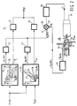
- FIG. 1 shows an embodiment of an electronic continuously variable transmission.
- the transmission 1 comprises a primary shaft 2, on which a primary pulley in the shape of primary pulley halves 3 and 4 is provided, said pulley half 3 being fixedly mounted on the primary shaft 2 and said primary pulley half 4 being movable on the shaft 2.
- the axially movable pulley 4 is movable by exerting a hydraulic pressure in a cylinder space 5.
- the control of the pressure in the cylinder space 5 takes place by a primary control unit 6 connected to the cylinder space 5, the function of said control unit being to adjust the radius of a driving belt 7 provided between the pulley halves 3 and 4 by controlling the pressure in the cylinder space 5.
- the transmission 1 furthermore comprises a secondary shaft 8, on which a pulley having secondary pulley halves 9 and 10 is provided, said pulley half 9 being fixedly mounted on the shaft 8 and said pulley half 10 being movably provided on the shaft 8.
- the pulley half 10, which is axially movable on the shaft, is moved by exerting a pressure in a cylinder space 11 connected to secondary electronic control unit 12.
- the control units 6 and 12 respectively are connected to the cylinder spaces 5 and 11 respectively by means of lines 13 and 14 respectively.
- the tension in the driving belt 7, which is furthermore provided between the secondary pulley halves 9 and 10, is maintained in that the secondary electronic control unit 12 exerts a suitable pressure in the cylinder space 11.
- the transmission ratio or the tension force in the driving belt 7, as the case may be, is hydraulically influenced by the control units 6 and 12 respectively.
- the control units 6 and 12 contain primary and secondary moving means to be further discussed hereafter.
- Said moving means do not necessarily have to be designed for influencing the transmission ratio and the tension force in a hydraulic manner, but it is conceivable that said moving means are of an electro-mechanical nature, and for that purpose comprise electro-mechanical converters, so as to enable an influencing of the transmission ratio or the tension force, as the case may be, by moving the pulley halves 4 or 10, as the case may be.
- the electro-mechanical primary and secondary moving means may e.g. contain a worm wheel to be rotated, by means of which worm wheel the pulley halves 4 and 10 are moved in axial direction.
- the hydraulic version of the primary and secondary moving means will be explained in more detail hereafter.
- the transmission 1 furthermore contains a motor 15 coupled to the primary shaft 2, which motor is controlled by means of a throttle 16 coupled to an accelerator pedal (not shown), which receives an electric signal from a terminal ( ⁇ ), which is connected to the primary electronic control unit 6.
- the transmission 1 furthermore contains further electronic control means 17, which are connected to a terminal (T pr ) of the secondary electronic control unit 12.
- the output signal of said further control means 17 is led, via a command input (C), to clutch means 18 coupled to the secondary shaft 8.
- the clutch means 18 transmit the torque eventually controlled by the transmission to the wheels (not shown) of a vehicle.
- the clutch or lock-up means 18 are engaged or disengaged, as the case may be, by means of a signal on the command input (C), said signal being derived, by further electronic control means 17 yet to be explained, from a signal on the terminal (T pr ), which in turn can be derived from the control unit 12.
- the clutch or lock-up means 18 e.g. a torque converter
- the secondary pulley when seen in the driving direction. It will be apparent, however, that within the framework of the invention said means 18 may also be provided in another configuration or at another location in the transmission, e.g. on the primary shaft, without any problem.
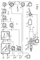
- FIG. 2 shows a fully elaborated preferred embodiment of the primary electronic control unit 6.
- the control unit 6 are connected to a terminal ( ⁇ ) and to a terminal (N s ), and contain first selection means 20 and second selection means 21, which are connected, via respective adjustable damping means 22 and 23, to the summing input 24 of a differentiator 25.
- Said differentiator 25 furthermore contains a differential input 26 and an output 27, which is coupled, via a PID-controller 28, to primary moving means 29.
- Said primary moving means 29, which are hydraulic moving means in the illustrated embodiment, have an ingoing line 30 and an outgoing line 13, in which the hydraulic pressure for the cylinder space 5 is generated.
- the line 13 is coupled, via a converter 31, to the differential input 26 of the differentiator 35.
- the selection means 20 and 21 respectively have outputs ( ⁇ E ) and ( ⁇ var ), which are interconnected via adjustable damping means 32 and 33 respectively, and which are connected to the terminal ( ⁇ ), which is connected to the throttle 16 containing adjusting means.
- an output signal N p (DV) is derived on the basis of the signal ( ⁇ ) in a manner to be further described hereafter, said output signal forming a measure for the desired value of the rpm of the primary shaft 2.
- Said signal is offered to the differentiator via either damping means 22 or 23, which reduces the variation in the signal it is supplied, to which differentiator a signal N p (MV), i.e. the measured value of the rpm of the primary shaft 2, is supplied, also via the differential input 26, on the basis of which the difference signal is made available to the output 27 in the differentiator 25.
- the primary moving means 29 are arranged such that they reduce a pressure P sec prevalent in the line 13, in such a manner that in said line a pressure P prim is prevalent, by means of which the pressure in the cylinder space 5, and thus the transmission ratio, is adjusted.
- a signal to be supplied to the differential input 26 is converted, said signal containing a measure for the measured value N p (MV), which is a measure for the primary rpm measured.
- the first selection means 20 contains a memory, in which characteristics are stored which contain data comprising the motor torque values (T m ) associated with the relevant position ( ⁇ ) of the accelerator pedal versus the values (N p ) of the rpm's of the primary shaft.
- T m motor torque values
- N p values of the rpm's of the primary shaft.
- the characteristic trend of said data is schematically illustrated in block 20.
- the selection means 20 will furthermore contain a memory, in which data are stored comprising the connection between the values of the rpm (N p ) of the primary shaft 2 and the corresponding adjustments of the engine throttle.
- the selection means 21 are selected, which contain a memory in which data are stored which comprise a desired connection between the value (N s ) of the rpm of the secondary shaft 8 and the value (N p ), which represents the rpm of the primary shaft 2.
- This connection is schematically illustrated in block 21.
- This curvilinear, parabolic connection which lies between extreme values of the transmission ratio i, which is defined as N p : N s , is also dependent on the manner in which, when the rpm of the secondary shaft 2, which is generally proportional to the vehicle speed, varies, the corresponding desired value N p (DV) of the rpm of the primary shaft varies in dependence on ( ⁇ ).
- the value (N s ) is derived from a signal present on a terminal (N s ), which is connected to means (not shown) for measuring the rpm of the secondary shaft, and which contains a measure for said rpm.
- the value of N p (DV) thus selected on the basis of N s is led to the control loop via the output of the selection means 21, in which circuit the primary moving means 29 are incorporated.
- Furthermore data will be stored in a memory of the selection means, which data represent the desired connection between N p (DV) and the corresponding throttle adjustment ⁇ var .
- the signal which contains a measure for ⁇ var is supplied to terminal ⁇ via the damping means 33.
- the manner in which the operating mode of the transmission is selected, by selecting the first selection means 20 or the second selection means 21, as the case may be, may take place either manually or in a manner whereby, when the accelerator pedal is influenced in an even manner, an automatic selection is made for the first selection means, and whereby in case of a so-called "kickdown" on the accelerator pedal the option of a normal or a sporting performance is automatically selected by the selection of the selecting means 21,
- the further selection of a desired normal or sporting performance, in case the selection means 21 have been selected may e.g. be done manually.
- the second selection means will thereby select such an N p (DV) with each N s that a constant transmission ratio is achieved.
- N p (DV) is a desirable addition, in particular when the transmission is used in vehicles.
- the driver of the vehicle would thereby have an option to interfere with the control, e.g. manually, by setting a desired transmission ratio N e /N s which is constantly set by second selection means 21, in that case by constant selection of the value N p (DV).
- the various set constants and time constants in the PID-controller 28 can be influenced by e.g.
- the various action in the controller 28 can be made dependent on the values of e.g. the parameters ⁇ , N s , N p (DV), ⁇ E or ⁇ var .
- the controller 28 may furthermore be self-learning.
- the converter 31 is arranged in such a manner that it could determine the rpm N p (MV) of the primary shaft 2 on the basis of the pressure P prim in the line 13, which pressure is proportional to the transmission ratio, given the known value N s of the rpm of the secondary shaft 8.
- FIG. 3 shows the podsible arrangement of the secondary electronic control unit 12.
- the control unit 12 contains memory/processing means 34 having an input connected to the terminal and an input connected to the terminal (N m ). Furthermore the means 34 have an output (T m ).
- the control unit 12 furthermore has first correction means 35, with a first input 36 connected to the terminal (T m ) and a second input 39 connected to an output 37 of a first arithmetic unit 38.
- Said arithmetic unit 38 has a first input 40 connected to the terminal (N m ) and a second input 41 connected to the terminal N p .
- the signal on the input 39 contains a measure for the quotient of N p and N m .
- the control unit 12 furthermore contains a second arithmetic unit 42 having a first input 43 connected to the terminal (N p ) and a second input 44 connected to a terminal (N s ).
- the arithmetic unit has an output 45, from which a signal can be derived which contains a measure for the transmission ratio, which is defined as the quotient of N p and N s .
- a third arithmetic unit 46 has two inputs 47 and 48, the first input 47 of which is connected to the terminal T pr and the second input 48 of which is connected to the output 45 of the second arithmetic unit 42.
- control unit 12 contains a fourth arithmetic unit 49 having an input 50 connected to the output 45 and an output 51, from which a signal can be derived which contains a measure for the radius R sec of the driving belt 7 between the secondary pulley halves 9 and 10, and a fifth arithmetic unit 52 having a first input 54 connected to an output 53 of the third arithmetic unit 46 and a second input 55 connected to the output 51. From an output 56 of the fifth arithmetic unit 52 a signal can be derived, in a manner to be explained hereafter, which contains a measure for the required pressure P sec , on the basis of which the tension in the driving belt 7 is controlled by adjusting the pressure in the cylinder space 11.
- the illustrated embodiment furthermore contains a sixth arithmetic unit 57 incorporated in the control unit 12, which has an input 58 and an output 59, and a seventh arithmetic unit 60 having a first input 61, a second input 62, and an output 63.
- the input 58 is connected to the terminal (N s )
- the second input 62 is connected to the output 59
- the first input 61 of the arithmetic unit 60 is coupled to the output 56 of the fifth arithmetic unit 52, via an arithmetic unit 64 incorporated in the control unit 12, said arithmetic unit 64 having a first input 65 connected to the output 56, a second input 66 and an output 67.
- Adjustable damping means 68 are provided between the output 67 and the input 61. Like the aforesaid adjustable damping means 22, 23, 32, 33 the adjustable damping means 68 contain electronic means, on the basis of which an amplitude variation in the input signal is reduced, whereby in general the reduction in a rising gradient of the input signal will be different from a reduction with regard to a decreasing gradient in the input signal in question.
- the output 63 of the seventh arithmetic unit may be coupled, via an adjustable limiter 168, to an input 69 of a differentiator 70.
- the differentiator 70 forms part of a control loop, in which there is furthermore incorporated a PID-controller 72 coupled to an output 71 of the differentiator 70, said PID-controller having an output 73 which is connected to secondary moving means 74.
- the moving means 74 are provided with an ingoing line 75, which is coupled to a pump (not shown) and an outgoing line 76.
- the pressure P sec (MV) in the line 76 is controlled in dependence on the output signal on the output 73, in that the line 76 is connected to a converter 77, which contains an output 78 which is connected to a differential input 79 of the differentiator 70.
- the converter 77 is arranged in such a way that it effects a conversion of the hydraulic pressure in the outgoing line 76 to a signal on the output 78, which signal will generally be electrical and which is suitable for being processed by the differentiator 70.
- the pressure P sec (MV) forms the value thus measured of the pressure in the cylinder space 11, by means of which the tension force in the driving belt 7 is controlled on the basis of the parameters ⁇ , N m , N p or N s . Also the actions in the PID-controller 72 are adjusted such that they ensure an optimum and stable influencing of the pressure P sec (MV).
- the starting point in the operation of the secondary electric control unit 12 is formed by the data stored in the memory of said control means, said data comprising the values T m associated with the motor torque values N m of the engine rpm, in dependence on the possible settings of the engine throttle 16.
- T m associated with the motor torque values N m of the engine rpm
- T pr On the basis of data stored in a memory of the first correction means 35, which data comprise the connection between the torque T pr produced at the primary pulley of the motor, and the quotient of N p and N m an estimate is made of T pr , which is supplied to the input 47.
- T pr and i On the basis of the signal supplied to the second input 48, which contains a measure for the transmission ratio, the product of T pr and i is determined in the third arithmetic unit 46, and said product is supplied to the input 54 in the shape of a signal T sec .
- a computation is carried out in the fifth arithmetic unit 52, the result of which is supplied to the input 65 in the shape of an estimate for P sec .
- a signal is supplied which corresponds with e.g. a pressure of 2 bar, which in the arithmetic unit 64 is added to the signal on the input 65 and which is then supplied to the input 61 of the arithmetic unit 60 via the adjustable damping means 68.
- T sec represents the torque to be supplied to the vehicle
- » is the coefficient of friction
- R sec is the secondary radius of the driving belt
- a s is the effective surface, with which the pressure in the secondary moving means is controlled by means of a plunger provided therein
- C is a constant.
- the arithmetic unit 60 subtracts the signal on the input 62 from the signal on the input 61, the difference being supplied to the output 63.
- the factor P sec (CENTR) will play an important role, in particular with higher secondary rpm's of the shaft 8.
- a desired secondary pressure P sec (DV) is supplied to the differentiator 70, said pressure being a function of the parameters ⁇ , N m , N p and N s .
- the circuit will be arranged in such a manner that when the signal on the output 73 is zero the secondary pressure will be maximal, in order that, irrespective of a possible failure in the functioning of the control means 12, the tension of the driving belt is controlled such that the functioning of the transmission 1, be it not optimal, is ensured.
- FIG. 4 shows the possible arrangement of the further electronic control means 17, and a part of the clutch/lock-up means 18.
- the further electronic control means 17 contain a ninth arithmetic unit 80 having an input 81 connected to the terminal T pr and an output 82.
- the output 82 is connected to a first input 83 of a tenth arithmetic unit 84, which furthermore has a second input 85 and an output 86.
- the signal on the input 85 represents an additional pressure, which is added to the signal P thr on the input 83, whereby the eventual sum is made available to the output 86.
- the output 86 is coupled to the terminal (C) via adjustable damping means 87 (if present) and a converter 88.
- Said converter 88 converts the desired value of the pressure P thr into a signal which is suitable for influencing a valve 89 incorporated in the block 18.
- the converter 88 will generally be provided with a suitably adjustable PID-controller for that purpose.
- the valve 89 has an ingoing line 90, in which a hydraulic pressure P sec is realised by means of a pump (not shown) and an outgoing line 91, in which a pressure influenced by means of the further electronic control means 17 is realised for a valve 92, which may e.g. be manually controlled.
- the signal P thr may also be used for engaging a clutch/torque converter 93. If required the engagement of the clutch/torque converter 93 may be made dependent on the operating mode connected with the "economical", "normal” or “sporting" driving style.
- the engagement of the clutch/lock-up of the torque converter 93 can furthermore be made dependent on certain requirements being met by the aforesaid parameters or on a combination of the aforesaid parameters.
- Said engagement may e.g. be made dependent on certain limits being exceeded, or the reverse, by the parameters or the parameter combinations.
- parameters or parameter combinations include: ⁇ , d ⁇ /dt, i, N s , N p , N m /N p , dN s /dt or for example the temperature of e.g. the brakes or the slip torque of the belt.
- the limiting values may be made dependent again on the specific operating mode which is required.
- valve 89 may be incorporated in a control loop, in which case the line 89 also must be connected to a converter (not shown), however, which is to be connected to a differentiator (not shown) to be provided between the adjustable damping means 87 and the converter 88.
- the previously explained memories in the means 20, 21, 34 and 35 may e.g. be in the shape of a rom, prom, an E-prom or an EE-prom.
- the electronically controlled continuously variable transmission explained above may be extended in a simple manner into an even more advanced transmission.
- suitable signals e.g. the secondary electronic control unit 12, said signals containing a measure for any torque variations caused by the motor or e.g. the road.
- Such torque variations may namely lead to undesirable slip of the driving belt 7 across the various pulley halves.
- Said slip may be prevented in that, even before said torque variations reach the transmission, the secondary pressure is influenced, and generally enhanced, in such a manner that such torque variations do not lead to said undesirable slip. It is necessary in that case that the possibility of torque variations occurring is recognized at an early stage. It is possible to anticipate the torque variations caused by the motor when the motor torque field of the motor used is known.
- This motor torque field is stored in the means 34 and is thus used in the embodiment of Figure 3 to realise a certain adaptation of the secondary pressure, given a certain variation in the position of the throttle and the change of the motor torque connected therewith.
- a normal operation of the transmission i.e. the drive position
- the various operating situations such as: “low”, “medium” or “overdrive”
- the secondary electronic control unit 12 may thus be arranged in such a manner that this fact is taken into account, so that the tension in the driving belt 7 is at all times optimally adapted to the torque to be transmitted.
- Indicators that are in principle suitable include:
- the above indicators are in principle usable, but they provide measuring magnitudes which occur substantially simultaneously with the occurring torque variations. Measuring magnitudes which on the other hand anticipate torque variations in the transmission include:
- Information that anticipates even further is provided by measuring the unevenness of the road surface by means of e.g. microwaves or laser-doppler sensors.
- Said sensors are blank contact transducers, which are already used with so-called active suspension systems. Since the information provided by said sensors anticipates so far ahead, ample computing time and control time is available so as to have the secondary pressure adjusted at the correct moment. It appears that even at a speed of 100 km/h a period of about 18 milliseconds is still available.
- Sensor means 94 of the type explained above are schematically indicated in Figure 3. In the illustrated embodiment of the secondary electronic control unit 12 said sensor means 94 are connected to a third input 95 of the seventh arithmetic unit 60, so as to influence the secondary pressure additionally by means of the signal on the third input.
- the electro-mechanical means explained above with reference to Figures 2, 3 and 4, viz. the primary moving means 29, the secondary moving means 74 and the valve 89 may, as already said before, be of electromechanical design.
- a preferred embodiment of such electromechanical means provided with reference numeral 96 is illustrated in Figure 5.
- the means 96 illustrated in this embodiment comprise a valve body 97, which is axially movable within a space 98 under the influence of a movable core 100 accommodated in a coil 99.
- the valve body 97 bears against a spring 101, whose bias can be set by means of an adjusting screw 102.
- the construction of the valve body 97 is such that said valve body narrows in the space 98, from an effective surface A1 to an effective surface A2, which is smaller than A1.
- Lines 103 and 104 terminate in the space 98, whose passages may be controlled by moving the valve body 97.
- a pump (not shown) may e.g. be connected to the line 103, whereby the line 104 can be used as a blow-off for the fluid to be delivered by the pump.
- By driving the coil 99 it is possible to influence the axial position, and thus the passage, so that in that case a pressure is effected in the line 103 which is dependent on the current through the coil 99. If a fluid pressure is present in the space 98 a net force against the spring force of the spring 101 will co-operate with the force exerted by the coil 99, and a required position of the valve body 97 will be adjusted on the basis of this equilibrium of forces.
- the net force produced by the hydraulic pressure in the space 98 works against the spring pressure, since the effective surface A1 is larger than the effective surface A2.
- the electro-mechanical means 96 thus work directly, i.e. they function as a direct converter of the electric current I into a required hydraulic pressure.
- the use of a pilot valve or an auxiliary valve, as was usual, has become redundant as a result of this direct control method.
- the electromechanical means 96 will be incorporated in a control loop, in order to reduce their sensitivity to the effect that the pressure in the space 98 has on control behaviour of said means, a converter 105 connected to the line 103 for converting the hydraulic pressure in the line 103 into a corresponding electric signal P(MV) being present in said control loop.
- Said control loop furthermore contains a differential amplifier 106 having two inputs, viz. P(MV) and P(DV), and one output 107, to which the coil 99 is connected. As long as the differential amplifier detects a differential signal between the measured value P(MV) and the required value P(DV), said amplifier will effect a current through the coil 99 so as to move the valve body 97, until an equilibrium has been adjusted and both signal are equal to each other.
- a very important advantage from a point of view of safety is that, in the unlikely event of a power failure, the electro-mechanical means automatically assume a position, under the influence of the spring, in which a safe high pressure is set. In that case the transmission keeps functioning in spite of the power failure.
- the electro-mechanical means may be designed such that in the event of a power failure a constant lower pressure is set. Besides the electro-mechanical means also additional control means may be provided which, only in the event of a power failure, set the high or low pressure adjusted by the electro-mechanical means to a required pressure level. Two possible embodiments are illustrated in Figures 6 and 7.
- FIG. 6 shows a primary electronic control unit 6 which, insofar as it corresponds with Figure 2, has been given the same numerals.
- the primary moving means 29 are again in the shape of hydraulic moving means and have an ingoing line 30 with a P sec and an outgoing line 13 with the set pressure P prim .
- Hydraulic medium can be discharged via an outgoing line 111.
- the valve body 112 will move to the right under the influence of the spring 113, as a result of which the ingoing line 30 is no longer in contact with the ingoing line 13.
- There is a connection between the line 13 and the line 111 so that hydraulic medium will flow from the line 13 via the line 111.
- control according to Figure 6 is furthermore provided with an on/off solenoid 114 and a safety valve 117.
- the safety valve 117 is placed in the line 13 of P prim .
- the on/off solenoid 114 is provided with an ingoing line 115 and an outgoing line 116, which is coupled to the safety valve 117.
- FIG. 7 shows a secondary electronic control unit which, insofar as it corresponds with Figure 2, has been given the same numerals.
- the moving means 74 are provided with an ingoing line 75, which is again coupled to a pump (not shown) and an outgoing line 76.
- the moving means 74 are designed such, however, that in the event of a power failure the connection between the ingoing line 75 (P sec ) and the outgoing line becomes maximal, because in the event of a power failure the valve body 121 is completely pushed to the right in Figure 7 under the influence of the spring 122.
- P sec is set to a safe pressure in the line 75, as a result of the large discharge of medium via the line 76. Said P sec cannot be optimal, however, e.g.
- a hydraulic auxiliary valve 123 is provided in the discharge line 76.
- Said auxiliary valve 123 has a valve body 124 and a spring 125. Furthermore the pressure of the discharge line 76 acts on the valve 124 at 126. Said pressure of the discharge line 76 at 126 acts against the spring 125. On the other hand the spring 125 is supported again at 127 by the pressure P sec in the line 75.
- electro-mechanical means may be provided with several supply and/or discharge lines, as well as with control edges.
- the valve body 97 itself may also serve as a core for the coil 99.
- the electro-mechanical means in particular those wherein the valve body is directly connected to the core of the coil or wherein the valve body itself functions as a core, instability of hysteresis may occur when the coil is driven with a certain current. According to the invention this can be largely prevented, however, by providing a dither frequency on the current.
- control may furthermore be self-learning, in such a manner that the driving current, without control steps, is directly taken to the required value, after which the control takes over the current adjustment.
Landscapes
- Engineering & Computer Science (AREA)
- Mechanical Engineering (AREA)
- Combustion & Propulsion (AREA)
- Chemical & Material Sciences (AREA)
- Transportation (AREA)
- General Engineering & Computer Science (AREA)
- Automation & Control Theory (AREA)
- Control Of Transmission Device (AREA)
- Valve Device For Special Equipments (AREA)
- Reduction Or Emphasis Of Bandwidth Of Signals (AREA)
- Gear-Shifting Mechanisms (AREA)
- Magnetically Actuated Valves (AREA)
- Earth Drilling (AREA)
- Valves And Accessory Devices For Braking Systems (AREA)
Abstract
Description
- The invention relates to an electronically controlled continuously variable transmission, provided with a driving belt, which is disposed between a primary pulley provided on a primary shaft, and a secondary pulley provided on a secondary shaft, whereby each pulley has corresponding conical pulley halves and at least one of said corresponding pulley halves is axially movable by means of primary and secondary moving means connected to a primary pulley half and a secondary pulley half respectively, which electronically controlled continuously variable transmission comprises an electronic control unit for adjusting the transmission ratio.
- Such a controlled continuously variable transmission is known from GB-A-2.058.257. This known transmission is provided with a hydraulic system comprising two valves controlling the flow to and from hydraulic cylinders of the movable pully halves of the primary and secondary pulley, to set the transmission ratio. The two valves are electronically controlled. Further the hydraulic system is provided with an accumulator to provide a constant pressure in the hydraulic system and accordingly provide a constant tension of the belt.
- The object of the invention is to provide a more efficient transmission.
- For that purpose the electronically controlled continuously variable transmission according to the invention is characterized by the features set out in the second part of claim 1.
- The advantage of the transmission according to the invention is that an improvement has been achieved with regard to the separation between the primary and the secondary electronic control units, the flexibility and the possibility of influencing the transmission ratio and the tension force in dependence on several parameters to be selected.
- As a result the transmission according to the invention has a considerably improved efficiency and an extended life.
- One embodiment of the electronic continuously variable transmission is according to the invention characterized in that the primary electronic control unit comprises selection means, in which mutually different data are stored in memories, said data relating to a certain optimum selection with regard to the operating mode of the transmission.
- The advantage of this embodiment is that it is made possible for the driver of a vehicle, in which the transmission is provided, to realise the performance he requires at a certain moment by a suitable selection of one of various selection means. The options to be selected comprise e.g. the possibility of driving with mimimal fuel consumption, with an enhanced accelerating power or e.g. with maximum comfort, whereby the variations in the transmission ratio are reduced as much as possible.
- In order to realise a minimal fuel consumption with a first option, whereby a minimum amount of exhaust fumes is produced, the transmission according to the invention is characterized in that a signal is supplied to an input of the first selection means, which signal contains a measure for the position of an accelerator pedal of an engine coupled to the transmission, and that on the basis of the type of engine an optimum selection for the momentaneously desired value of the rotational speed, hereinafter referred to as rpm, of the primary shaft is made from data stored in the memory, said data comprising the motor torque values associated with the relevant position of the accelerator pedal versus the values of the corresponding rpm's of the primary shaft, and that said selection is supplied to an output coupled to the primary moving means, so as to influence the transmission ratio.
- In a further embodiment the transmission according to the invention is characterized in that a signal is supplied to an input of the second selection means, which signal contains a measure for the position of an accelerator pedal of an engine coupled to the transmission, whereby on the basis of the signal and on the basis of a signal supplied to an input of the second selection means, which signal contains a measure for the rpm of the secondary shaft, an optimum selection for the momentaneously desired value of the rpm of the primary shaft is made from data stored in a memory of the second selection means, said data comprising a desired connection between the values of the rpm's of the secondary shaft and the primary shaft, and that said selection is supplied to an output coupled to the primary moving means, so as to influence the transmission ratio.
- The advantage of this further embodiment of the transmission according to the invention is that this second option by itself makes it possible again to differentiate as to the degree in which a sporting performance is required, by specifically establishing the required connection between the rpm's of the secondary shaft and the primary shaft. This required connection is preferably established in an electronical manner, so that it is not necessary to influence the position of the engine throttle by realising a certain shape of a cam coupled to the accelerator pedal.
- Preferably the transmission according to the invention is provided with adjustable damping means, which are connected between the output of the first or the second selection means and the primary moving means.
- The advantage of using adjustable damping means is that by reducing the degree of change in the signal carried to the primary moving means it is prevented that overly quick variations in the transmission ratio can occur. This prolongs the life of the transmission, since the amount of wear is reduced.
- Another preferred embodiment of the transmission is according the invention characterized in that the secondary electronic control unit contain memory means, in which data are stored which comprise values, associated with the motor torque values, of the rpm of the engine in dependence on the settings of the engine throttle, that the control unit has two inputs for supplying a signal containing a measure for the actual position of the throttle to the first input and for supplying a signal containing a measure for the actual rpm to the second input, as well as processing means connected to the memory means for delivering a further signal containing a measure for the torque produced by the engine to the output of the processing means, and that the output of the processing means is coupled to the secondary moving means for controlling the tension in the driving belt on the basis of the further signal.
- The advantage of this further embodiment of the transmission according to the invention is that the tension in the driving belt can be set in dependence on the estimated actual torque produced by the engine, so that said power can be transmitted by the transmission at all times, without any slip of the driving belt on the pulley halves.
- Another embodiment of the transmission according to the invention is characterized in that the secondary control unit contains first correction means provided with two inputs and one output and a first arithmetic unit provided with two inputs and one output, whereby the first input of the arithmetic unit is connected to the second input of the secondary control means, the second input of the arithmetic unit is connected to a terminal (Np), to which a signal is to be supplied which contains a measure for the value of the torque (Np) of the primary shaft and whereby at the output of the arithmetic unit connected to the second input of the first correction means a signal is generated, which contains a measure for the quotient of (Np) and (Nm), whereby the first input of the first correction means is connected to the output of the processing means, and whereby the output of the first correction means is coupled to the secondary moving means.
- The advantage of this embodiment of the transmission according to the invention is that at the output of the first correction means a signal is generated which is corrected for any slip, being the quotient of (Np) and (Nm), so that the slip is taken into account when the tension in the driving belt is being influenced. The accuracy of the estimate of the torque of the primary shaft has been enhanced by this measure, so that the tension force of the driving belt is adjusted accurately.
- Yet another embodiment of the transmission is according to the invention characterized in that the secondary control unit contains a second and a third arithmetic unit, each unit being provided with two inputs and one output, whereby the first input of the second arithmetic unit is connected to a terminal (Np), to which a signal is to be supplied which contains a measure for the value of the rpm (Np) of the primary shaft, and whereby the second input of the second arithmetic unit is connected to a terminal (Ns), to which a signal is to be supplied which contains a measure for the value of the rpm (Ns) of the secondary shaft, and a signal is generated, at the output of the second arithmetic unit connected to the second input of the third arithmetic unit, which contains a measure for the transmission ratio, whereby the first input of the third arithmetic unit is coupled to the output of the first correction means, and whereby the output of the third arithmetic unit is coupled to the secondary moving means.
- This embodiment of the transmission according to the invention makes it possible to render the tension force in the driving belt also dependent on the momentaneous transmission ratio. Since this leads to an average decrease of the tension force, the life of the driving belt is further prolonged.
- Yet another embodiment of the transmission is according to the invention characterized in that the secondary control unit contains a fourth arithmetic unit having one input and one output, and a fifth arithmetic unit having two inputs and one output, whereby the input of the fourth arithmetic unit is connected to the output of the second arithmetic unit, so as to generate a signal at the output of the fourth arithmetic unit which contains a measure for the secondary radius (Rs) of the driving belt, which is movable between the secondary pulley halves, whereby the output of the fourth arithmetic unit is connected to the second input of the fifth arithmetic unit and the first input of the fifth arithmetic unit is connected is connected to the output of the third arithmetic unit, and whereby the output of the fifth arithmetic unit is coupled to the secondary moving means.
- The advantage of this embodiment of the transmission according to the invention is that the estimate for the tension in the driving belt, given a factor to be incorporated in the fourth arithmetic unit, said factor depending on the concrete geometric design of the transmission, is controlled in co-dependence on the actual secondary radius of the driving belt.
- Yet another embodiment of the transmission is according to the invention characterized in that the secondary control unit contains a sixth arithmetic unit having one input and one output and a seventh arithmetic unit having two inputs and one output, whereby the input of the sixth arithmetic unit is connected to the terminal (Ns), the output of the sixth arithmetic unit is connected to the second input of the seventh arithmetic unit and the first input of the seventh arithmetic unit is coupled to the output of the third arithmetic unit, so as to reduce, with higher rpm's of the secondary shaft, the measure in the output signal of the seventh arithmetic unit which controls the tension force in the driving belt.
- The advantage of this embodiment of the transmission according to the invention is that in particular the wear of the driving belt occurring at higher rpm's, as a result of an overly high tension force, is reduced. In practice it appears namely that in particular with higher velocities of revolutions the tension force of the driving belt can be substantially reduced, as a result of which the amount of wear is further decreased.
- The invention and its further advantages will be further discussed with reference to the drawing, in which:
- Figure 1 is a diagrammatic illustration of an embodiment of the electronic continuously variable transmission according to the invention;
- Figure 2 shows a primary electronic control unit for use in the transmission according to Figure 1;
- Figure 3 shows a secondary electronic control unit for use in the transmission according to Figure 1;
- Figure 4 shows a further electronic control unit for use in the transmission according to Figure 1;
- Figure 5 shows a possible embodiment of electro-mechanical means for use in the transmission according to Figure 1;
- Figure 6 shows a further embodiment of primary electro-mechanical means for use in the transmission according to Figure 1, said means being provided with a safety valve; and
- Figure 7 shows a further embodiment of secondary electro-mechanical means for use in the transmission according to Figure 1, provided with a safety valve.
- Figure 1 shows an embodiment of an electronic continuously variable transmission. The transmission 1 comprises a
primary shaft 2, on which a primary pulley in the shape ofprimary pulley halves pulley half 3 being fixedly mounted on theprimary shaft 2 and saidprimary pulley half 4 being movable on theshaft 2. In the illustrated embodiment of the transmission 1 the axiallymovable pulley 4 is movable by exerting a hydraulic pressure in acylinder space 5. The control of the pressure in thecylinder space 5 takes place by aprimary control unit 6 connected to thecylinder space 5, the function of said control unit being to adjust the radius of adriving belt 7 provided between thepulley halves cylinder space 5. - The transmission 1 furthermore comprises a
secondary shaft 8, on which a pulley havingsecondary pulley halves pulley half 9 being fixedly mounted on theshaft 8 and saidpulley half 10 being movably provided on theshaft 8. Thepulley half 10, which is axially movable on the shaft, is moved by exerting a pressure in acylinder space 11 connected to secondaryelectronic control unit 12. - The
control units cylinder spaces lines driving belt 7, which is furthermore provided between thesecondary pulley halves electronic control unit 12 exerts a suitable pressure in thecylinder space 11. - The transmission ratio or the tension force in the
driving belt 7, as the case may be, is hydraulically influenced by thecontrol units control units pulley halves pulley halves - The transmission 1 furthermore contains a
motor 15 coupled to theprimary shaft 2, which motor is controlled by means of athrottle 16 coupled to an accelerator pedal (not shown), which receives an electric signal from a terminal (α), which is connected to the primaryelectronic control unit 6. - The transmission 1 furthermore contains further electronic control means 17, which are connected to a terminal (Tpr) of the secondary
electronic control unit 12. The output signal of said further control means 17 is led, via a command input (C), to clutch means 18 coupled to thesecondary shaft 8. The clutch means 18 transmit the torque eventually controlled by the transmission to the wheels (not shown) of a vehicle. The clutch or lock-up means 18 are engaged or disengaged, as the case may be, by means of a signal on the command input (C), said signal being derived, by further electronic control means 17 yet to be explained, from a signal on the terminal (Tpr), which in turn can be derived from thecontrol unit 12. - In the illustrated embodiment the clutch or lock-up means 18 (e.g. a torque converter) are provided behind the secondary pulley, when seen in the driving direction. It will be apparent, however, that within the framework of the invention said means 18 may also be provided in another configuration or at another location in the transmission, e.g. on the primary shaft, without any problem.
- Figure 2 shows a fully elaborated preferred embodiment of the primary
electronic control unit 6. Thecontrol unit 6 are connected to a terminal (α) and to a terminal (Ns), and contain first selection means 20 and second selection means 21, which are connected, via respective adjustable damping means 22 and 23, to thesumming input 24 of adifferentiator 25. Saiddifferentiator 25 furthermore contains adifferential input 26 and anoutput 27, which is coupled, via a PID-controller 28, to primary moving means 29. Said primary moving means 29, which are hydraulic moving means in the illustrated embodiment, have aningoing line 30 and anoutgoing line 13, in which the hydraulic pressure for thecylinder space 5 is generated. Theline 13 is coupled, via aconverter 31, to thedifferential input 26 of thedifferentiator 35. Besides outputs Np(DV) connected to the adjustable damping means 22 and 23 the selection means 20 and 21 respectively have outputs (βE) and (βvar), which are interconnected via adjustable damping means 32 and 33 respectively, and which are connected to the terminal (β), which is connected to thethrottle 16 containing adjusting means. - In the first and second selection means 20, 21 an output signal Np(DV) is derived on the basis of the signal (α) in a manner to be further described hereafter, said output signal forming a measure for the desired value of the rpm of the
primary shaft 2. Said signal is offered to the differentiator via either damping means 22 or 23, which reduces the variation in the signal it is supplied, to which differentiator a signal Np(MV), i.e. the measured value of the rpm of theprimary shaft 2, is supplied, also via thedifferential input 26, on the basis of which the difference signal is made available to theoutput 27 in thedifferentiator 25. The PID-controller 28, whose various actions can be adjusted in a suitable manner, influences the differential signal on theoutput 27 such that the primary moving means can be controlled by means of said signal. The primary moving means 29 are arranged such that they reduce a pressure Psec prevalent in theline 13, in such a manner that in said line a pressure Pprim is prevalent, by means of which the pressure in thecylinder space 5, and thus the transmission ratio, is adjusted. In theconverter 31, to which the signal Pprim is supplied, a signal to be supplied to thedifferential input 26 is converted, said signal containing a measure for the measured value Np(MV), which is a measure for the primary rpm measured. - The first selection means 20 contains a memory, in which characteristics are stored which contain data comprising the motor torque values (Tm) associated with the relevant position (α) of the accelerator pedal versus the values (Np) of the rpm's of the primary shaft. The characteristic trend of said data is schematically illustrated in
block 20. For each position (α) of the accelerator pedal an area around a desired value of the primary rpm can be indicated, within which the fuel take-up of the engine is minimal. Around this area further, so-called islands can be shown in the shape of more or less concentric areas, which indicate a gradually increasing fuel consumption. Thus an optimum selection of the momentaneously required value of the rpm of the primary shaft can be made in the selection means 20, and be supplied to the primary moving means 29 via the output Np(DV). If the measured value Np(MV) of the rpm of theprimary shaft 2 differs from the desired value Np(DV) the transmission ratio (i) is changed by the primary moving means 29 in such a manner that these two values correspond with one another. The selection means 20 will furthermore contain a memory, in which data are stored comprising the connection between the values of the rpm (Np) of theprimary shaft 2 and the corresponding adjustments of the engine throttle. When for an economical performance the selection means 20 have been selected, the value of the throttle adjustment (βE) corresponding herewith in the economical position will be determined on the basis of the optimum value Np(DV). This signal (βE) is supplied to the terminal via the dampingmeans 32. - When a normal performance or a sporting performance is required, the selection means 21 are selected, which contain a memory in which data are stored which comprise a desired connection between the value (Ns) of the rpm of the
secondary shaft 8 and the value (Np), which represents the rpm of theprimary shaft 2. This connection is schematically illustrated inblock 21. This curvilinear, parabolic connection which lies between extreme values of the transmission ratio i, which is defined as Np: Ns, is also dependent on the manner in which, when the rpm of thesecondary shaft 2, which is generally proportional to the vehicle speed, varies, the corresponding desired value Np(DV) of the rpm of the primary shaft varies in dependence on (β). The value (Ns) is derived from a signal present on a terminal (Ns), which is connected to means (not shown) for measuring the rpm of the secondary shaft, and which contains a measure for said rpm. The value of Np(DV) thus selected on the basis of Ns is led to the control loop via the output of the selection means 21, in which circuit the primary moving means 29 are incorporated. Furthermore data will be stored in a memory of the selection means, which data represent the desired connection between Np(DV) and the corresponding throttle adjustment βvar. The signal which contains a measure for βvar is supplied to terminal β via the dampingmeans 33. - The manner in which the operating mode of the transmission is selected, by selecting the first selection means 20 or the second selection means 21, as the case may be, may take place either manually or in a manner whereby, when the accelerator pedal is influenced in an even manner, an automatic selection is made for the first selection means, and whereby in case of a so-called "kickdown" on the accelerator pedal the option of a normal or a sporting performance is automatically selected by the selection of the selecting
means 21, The further selection of a desired normal or sporting performance, in case the selection means 21 have been selected, may e.g. be done manually. - Within the framework of this control it is also possible to influence this control in such a manner that a constant transmission ratio is set. The second selection means will thereby select such an Np(DV) with each Ns that a constant transmission ratio is achieved. This is a desirable addition, in particular when the transmission is used in vehicles. The driver of the vehicle would thereby have an option to interfere with the control, e.g. manually, by setting a desired transmission ratio Ne/Ns which is constantly set by second selection means 21, in that case by constant selection of the value Np(DV).
If required and necessary in practice the various set constants and time constants in the PID-controller 28 can be influenced by e.g. the selection of the first or the second selection means or by the degree to which a sporting performance is required. Possibly the various action in thecontroller 28 can be made dependent on the values of e.g. the parameters α, Ns, Np(DV), βE or βvar. Thecontroller 28 may furthermore be self-learning. - The
converter 31 is arranged in such a manner that it could determine the rpm Np(MV) of theprimary shaft 2 on the basis of the pressure Pprim in theline 13, which pressure is proportional to the transmission ratio, given the known value Ns of the rpm of thesecondary shaft 8. - Figure 3 shows the podsible arrangement of the secondary
electronic control unit 12. Thecontrol unit 12 contains memory/processing means 34 having an input connected to the terminal and an input connected to the terminal (Nm). Furthermore themeans 34 have an output (Tm). Thecontrol unit 12 furthermore has first correction means 35, with afirst input 36 connected to the terminal (Tm) and asecond input 39 connected to anoutput 37 of a firstarithmetic unit 38. Saidarithmetic unit 38 has afirst input 40 connected to the terminal (Nm) and asecond input 41 connected to the terminal Np. The signal on theinput 39 contains a measure for the quotient of Np and Nm. This quotient indicates any slip that occurs, when reduction means (not shown) are provided between themotor 15 and theprimary shaft 2. This quotient will generally be smaller than 1. Thecontrol unit 12 furthermore contains a second arithmetic unit 42 having a first input 43 connected to the terminal (Np) and asecond input 44 connected to a terminal (Ns). The arithmetic unit has an output 45, from which a signal can be derived which contains a measure for the transmission ratio, which is defined as the quotient of Np and Ns. A thirdarithmetic unit 46 has twoinputs first input 47 of which is connected to the terminal Tpr and thesecond input 48 of which is connected to the output 45 of the second arithmetic unit 42. Furthermore thecontrol unit 12 contains a fourtharithmetic unit 49 having aninput 50 connected to the output 45 and anoutput 51, from which a signal can be derived which contains a measure for the radius Rsec of the drivingbelt 7 between the secondary pulley halves 9 and 10, and a fiftharithmetic unit 52 having afirst input 54 connected to anoutput 53 of the thirdarithmetic unit 46 and asecond input 55 connected to theoutput 51. From anoutput 56 of the fifth arithmetic unit 52 a signal can be derived, in a manner to be explained hereafter, which contains a measure for the required pressure Psec, on the basis of which the tension in the drivingbelt 7 is controlled by adjusting the pressure in thecylinder space 11. - The illustrated embodiment furthermore contains a sixth
arithmetic unit 57 incorporated in thecontrol unit 12, which has aninput 58 and anoutput 59, and a seventharithmetic unit 60 having afirst input 61, asecond input 62, and anoutput 63. Theinput 58 is connected to the terminal (Ns), thesecond input 62 is connected to theoutput 59 and thefirst input 61 of thearithmetic unit 60 is coupled to theoutput 56 of the fiftharithmetic unit 52, via anarithmetic unit 64 incorporated in thecontrol unit 12, saidarithmetic unit 64 having afirst input 65 connected to theoutput 56, asecond input 66 and anoutput 67. Adjustable damping means 68 are provided between theoutput 67 and theinput 61. Like the aforesaid adjustable damping means 22, 23, 32, 33 the adjustable damping means 68 contain electronic means, on the basis of which an amplitude variation in the input signal is reduced, whereby in general the reduction in a rising gradient of the input signal will be different from a reduction with regard to a decreasing gradient in the input signal in question. Theoutput 63 of the seventh arithmetic unit may be coupled, via anadjustable limiter 168, to aninput 69 of adifferentiator 70. Thedifferentiator 70 forms part of a control loop, in which there is furthermore incorporated a PID-controller 72 coupled to anoutput 71 of thedifferentiator 70, said PID-controller having anoutput 73 which is connected to secondary moving means 74. The moving means 74 are provided with aningoing line 75, which is coupled to a pump (not shown) and anoutgoing line 76. The pressure Psec(MV) in theline 76 is controlled in dependence on the output signal on theoutput 73, in that theline 76 is connected to aconverter 77, which contains anoutput 78 which is connected to adifferential input 79 of thedifferentiator 70. Theconverter 77 is arranged in such a way that it effects a conversion of the hydraulic pressure in theoutgoing line 76 to a signal on theoutput 78, which signal will generally be electrical and which is suitable for being processed by thedifferentiator 70. The pressure Psec(MV) forms the value thus measured of the pressure in thecylinder space 11, by means of which the tension force in the drivingbelt 7 is controlled on the basis of the parameters α, Nm, Np or Ns. Also the actions in the PID-controller 72 are adjusted such that they ensure an optimum and stable influencing of the pressure Psec(MV). - The starting point in the operation of the secondary
electric control unit 12 is formed by the data stored in the memory of said control means, said data comprising the values Tm associated with the motor torque values Nm of the engine rpm, in dependence on the possible settings of theengine throttle 16. On the basis of the signals and Nm on the terminals in question of themeans 34 an estimate is made of the torque Tm produced by the motor, which estimate is supplied to theinput 36.Block 34 diagrammatically illustrates the relevant characteristics that play a role within this context. On the basis of data stored in a memory of the first correction means 35, which data comprise the connection between the torque Tpr produced at the primary pulley of the motor, and the quotient of Np and Nm an estimate is made of Tpr, which is supplied to theinput 47. On the basis of Tpr and on the basis of the signal supplied to thesecond input 48, which contains a measure for the transmission ratio, the product of Tpr and i is determined in the thirdarithmetic unit 46, and said product is supplied to theinput 54 in the shape of a signal Tsec. On the basis of the relation
arithmetic unit 52, the result of which is supplied to theinput 65 in the shape of an estimate for Psec. To thesecond input 66 of the eighth arithmetic unit 64 a signal is supplied which corresponds with e.g. a pressure of 2 bar, which in thearithmetic unit 64 is added to the signal on theinput 65 and which is then supplied to theinput 61 of thearithmetic unit 60 via the adjustable dampingmeans 68. To thesecond input 62 of said arithmetic unit 60 a signal Psec(CENTR) is supplied which is determined by the sixtharithmetic unit 57 by means of the signal Ns supplied thereto, on the basis of the relation
Tsec represents the torque to be supplied to the vehicle;
» is the coefficient of friction;
Rsec is the secondary radius of the driving belt;
As is the effective surface, with which the pressure in the secondary moving means is controlled by means of a plunger provided therein; and
C is a constant. - The
arithmetic unit 60 subtracts the signal on theinput 62 from the signal on theinput 61, the difference being supplied to theoutput 63. On account of the quadratic relation with regard to Ns the factor Psec (CENTR) will play an important role, in particular with higher secondary rpm's of theshaft 8. Eventually a desired secondary pressure Psec(DV) is supplied to thedifferentiator 70, said pressure being a function of the parameters β, Nm, Np and Ns. For safety reasons the circuit will be arranged in such a manner that when the signal on theoutput 73 is zero the secondary pressure will be maximal, in order that, irrespective of a possible failure in the functioning of the control means 12, the tension of the driving belt is controlled such that the functioning of the transmission 1, be it not optimal, is ensured. - Figure 4 shows the possible arrangement of the further electronic control means 17, and a part of the clutch/lock-up means 18. The further electronic control means 17 contain a ninth
arithmetic unit 80 having aninput 81 connected to the terminal Tpr and anoutput 82. For e.g. a fluid clutch thearithmetic unit 80 computes on the basis of the relation
Pthr is the hydraulic pressure required for operating the clutch/lock-up means 18;
» is the friction between the clutch plates;
A is the surface of the clutch plate;
n indicates the number of plates; and
R indicates the average radius. - The
output 82 is connected to afirst input 83 of a tenth arithmetic unit 84, which furthermore has asecond input 85 and anoutput 86. The signal on theinput 85 represents an additional pressure, which is added to the signal Pthr on theinput 83, whereby the eventual sum is made available to theoutput 86. Theoutput 86 is coupled to the terminal (C) via adjustable damping means 87 (if present) and aconverter 88. Saidconverter 88 converts the desired value of the pressure Pthr into a signal which is suitable for influencing avalve 89 incorporated in theblock 18. Theconverter 88 will generally be provided with a suitably adjustable PID-controller for that purpose. Thevalve 89 has aningoing line 90, in which a hydraulic pressure Psec is realised by means of a pump (not shown) and anoutgoing line 91, in which a pressure influenced by means of the further electronic control means 17 is realised for avalve 92, which may e.g. be manually controlled. The signal Pthr may also be used for engaging a clutch/torque converter 93. If required the engagement of the clutch/torque converter 93 may be made dependent on the operating mode connected with the "economical", "normal" or "sporting" driving style. With each of said selected driving styles the engagement of the clutch/lock-up of thetorque converter 93 can furthermore be made dependent on certain requirements being met by the aforesaid parameters or on a combination of the aforesaid parameters. Said engagement may e.g. be made dependent on certain limits being exceeded, or the reverse, by the parameters or the parameter combinations. Examples of parameters or parameter combinations include: α, dα/dt, i, Ns, Np, Nm/Np, dNs/dt or for example the temperature of e.g. the brakes or the slip torque of the belt. Also the limiting values may be made dependent again on the specific operating mode which is required. - If required the
valve 89 may be incorporated in a control loop, in which case theline 89 also must be connected to a converter (not shown), however, which is to be connected to a differentiator (not shown) to be provided between the adjustable damping means 87 and theconverter 88. - The previously explained memories in the
means - The electronically controlled continuously variable transmission explained above may be extended in a simple manner into an even more advanced transmission. Thus it is possible e.g. to supply suitable signals to e.g. the secondary
electronic control unit 12, said signals containing a measure for any torque variations caused by the motor or e.g. the road. Such torque variations may namely lead to undesirable slip of the drivingbelt 7 across the various pulley halves. Said slip may be prevented in that, even before said torque variations reach the transmission, the secondary pressure is influenced, and generally enhanced, in such a manner that such torque variations do not lead to said undesirable slip. It is necessary in that case that the possibility of torque variations occurring is recognized at an early stage. It is possible to anticipate the torque variations caused by the motor when the motor torque field of the motor used is known. This motor torque field is stored in themeans 34 and is thus used in the embodiment of Figure 3 to realise a certain adaptation of the secondary pressure, given a certain variation in the position of the throttle and the change of the motor torque connected therewith. When otherwise a distinction is made, with a normal operation of the transmission (i.e. the drive position) between the various operating situations, such as: "low", "medium" or "overdrive", it appears that dependent on the kind of operating situation the sensitivity for motor torque variations varies. It appears that the sensitivity of the transmission for motor torque variations is greatest in the "low" position. The secondaryelectronic control unit 12 may thus be arranged in such a manner that this fact is taken into account, so that the tension in the drivingbelt 7 is at all times optimally adapted to the torque to be transmitted. In practice such motor torque variations appear to be well-predictable from the moment the accelerator pedal is depressed. The time that lapses between the moment of acceleration and the moment at which the motor torque is built up generally amounts to a few tens of milliseconds. Another few tens of milliseconds later the torque of theprimary shaft 2 is equal to that of the motor. - On the other hand torque variations which originate in the road are unpredictable and therefore some form of indication is required, in order to be able to supply data to the various control means that contain a measure for the torque variations resulting from this. Indicators that are in principle suitable include:
- a) the torque occurring in the
secondary shaft 8; - b) the torsional rotation of the
secondary shaft 8; - c) the angular rotation of the wheels of the vehicle;
- d) the vertical (springing) movement of the wheels;
- e) the vertical bearing forces occurring in the wheel bearings in question.
- The above indicators are in principle usable, but they provide measuring magnitudes which occur substantially simultaneously with the occurring torque variations. Measuring magnitudes which on the other hand anticipate torque variations in the transmission include:
- a) the deformation of the tyres, which may e.g. be determined by means of strain gauges detecting the deformation of the rubber of the tyres so as to detect unevennesses in the road surface.
- b) the air pressure in the tyres;
- c) the horizontal bearing forces in the wheels;
- d) the reaction forces in the various supporting arms and reaction rods.
- Information that anticipates even further is provided by measuring the unevenness of the road surface by means of e.g. microwaves or laser-doppler sensors. Said sensors are blank contact transducers, which are already used with so-called active suspension systems. Since the information provided by said sensors anticipates so far ahead, ample computing time and control time is available so as to have the secondary pressure adjusted at the correct moment. It appears that even at a speed of 100 km/h a period of about 18 milliseconds is still available. Sensor means 94 of the type explained above are schematically indicated in Figure 3. In the illustrated embodiment of the secondary
electronic control unit 12 said sensor means 94 are connected to athird input 95 of the seventharithmetic unit 60, so as to influence the secondary pressure additionally by means of the signal on the third input. Thus a computation may be made in the sensor means 94, on the basis of the momentaneously available data as to possibly occurring torque variations. Said torque variations might lead to impermissible slip, on the basis of which it may be decided to influence the secondary pressure momentaneously, in order to reduce said possibly impermissible slip. - The electro-mechanical means explained above with reference to Figures 2, 3 and 4, viz. the primary moving means 29, the secondary moving means 74 and the
valve 89 may, as already said before, be of electromechanical design. A preferred embodiment of such electromechanical means provided withreference numeral 96 is illustrated in Figure 5. The means 96 illustrated in this embodiment comprise a valve body 97, which is axially movable within a space 98 under the influence of amovable core 100 accommodated in acoil 99. The valve body 97 bears against aspring 101, whose bias can be set by means of an adjustingscrew 102. The construction of the valve body 97 is such that said valve body narrows in the space 98, from an effective surface A1 to an effective surface A2, which is smaller than A1.Lines line 103, whereby theline 104 can be used as a blow-off for the fluid to be delivered by the pump. By driving thecoil 99 it is possible to influence the axial position, and thus the passage, so that in that case a pressure is effected in theline 103 which is dependent on the current through thecoil 99. If a fluid pressure is present in the space 98 a net force against the spring force of thespring 101 will co-operate with the force exerted by thecoil 99, and a required position of the valve body 97 will be adjusted on the basis of this equilibrium of forces. The net force produced by the hydraulic pressure in the space 98 works against the spring pressure, since the effective surface A1 is larger than the effective surface A2. Thus the hydraulic pressure in the space 98 is used to support the action of thecoil 99. The electro-mechanical means 96 thus work directly, i.e. they function as a direct converter of the electric current I into a required hydraulic pressure. The use of a pilot valve or an auxiliary valve, as was usual, has become redundant as a result of this direct control method. - The electromechanical means 96 will be incorporated in a control loop, in order to reduce their sensitivity to the effect that the pressure in the space 98 has on control behaviour of said means, a
converter 105 connected to theline 103 for converting the hydraulic pressure in theline 103 into a corresponding electric signal P(MV) being present in said control loop. Said control loop furthermore contains a differential amplifier 106 having two inputs, viz. P(MV) and P(DV), and oneoutput 107, to which thecoil 99 is connected. As long as the differential amplifier detects a differential signal between the measured value P(MV) and the required value P(DV), said amplifier will effect a current through thecoil 99 so as to move the valve body 97, until an equilibrium has been adjusted and both signal are equal to each other. - A very important advantage from a point of view of safety is that, in the unlikely event of a power failure, the electro-mechanical means automatically assume a position, under the influence of the spring, in which a safe high pressure is set. In that case the transmission keeps functioning in spite of the power failure.
- If such a high pressure is undesirable for a prolonged time, e.g. because it might result in damage to the transmission, the electro-mechanical means may be designed such that in the event of a power failure a constant lower pressure is set. Besides the electro-mechanical means also additional control means may be provided which, only in the event of a power failure, set the high or low pressure adjusted by the electro-mechanical means to a required pressure level. Two possible embodiments are illustrated in Figures 6 and 7.
- Figure 6 shows a primary
electronic control unit 6 which, insofar as it corresponds with Figure 2, has been given the same numerals. The primary moving means 29 are again in the shape of hydraulic moving means and have aningoing line 30 with a Psec and anoutgoing line 13 with the set pressure Pprim. Hydraulic medium can be discharged via anoutgoing line 111. In the event of a power failure thevalve body 112 will move to the right under the influence of thespring 113, as a result of which theingoing line 30 is no longer in contact with theingoing line 13. There is a connection between theline 13 and theline 111, so that hydraulic medium will flow from theline 13 via theline 111. As a result of this Pprim in theline 13 would quickly become lower in the event of a power failure, as a result of which the transmission would change down very quickly and the rpm would run up very fast. This is undesirable and is preferably avoided. For this purpose the control according to Figure 6 is furthermore provided with an on/offsolenoid 114 and asafety valve 117. Thesafety valve 117 is placed in theline 13 of Pprim. The on/offsolenoid 114 is provided with aningoing line 115 and anoutgoing line 116, which is coupled to thesafety valve 117. In the event of a power failure the on/offsolenoid 114 closes the connection between thelines line 116 to the safety valve is blacked out. Under the influence of thespring 118 thevalve body 119 of thesafety valve 117 will move to the right, so that theline 13 of Pprim is closed. As a result Pprim cannot become lower in the event of a power failure, except for a slight leakage in the control system, which is common. As a result of said leakage Pprim will decrease only slowly, the transmission will change down gradually and thus the engine rpm will also run up slowly. The driver will notice this and will have sufficient time to decelerate. Thus a safe primary electronic control is obtained, also in the event of a power failure. - Figure 7 shows a secondary electronic control unit which, insofar as it corresponds with Figure 2, has been given the same numerals. The moving means 74 are provided with an
ingoing line 75, which is again coupled to a pump (not shown) and anoutgoing line 76. In this case the moving means 74 are designed such, however, that in the event of a power failure the connection between the ingoing line 75 (Psec) and the outgoing line becomes maximal, because in the event of a power failure thevalve body 121 is completely pushed to the right in Figure 7 under the influence of thespring 122. In this case Psec is set to a safe pressure in theline 75, as a result of the large discharge of medium via theline 76. Said Psec cannot be optimal, however, e.g. to drive the transmission and thus the vehicle. In order to make it possible for the transmission to be driven even in the event of a power failure a hydraulicauxiliary valve 123 is provided in thedischarge line 76. Saidauxiliary valve 123 has avalve body 124 and aspring 125. Furthermore the pressure of thedischarge line 76 acts on thevalve 124 at 126. Said pressure of thedischarge line 76 at 126 acts against thespring 125. On the other hand thespring 125 is supported again at 127 by the pressure Psec in theline 75. - With normal use Psec at 127 will always be larger than the pressure in the
discharge line 76 at 126 so that, also under the influence of thespring 125, thevalve body 124 is mainly directed towards the right in Figure 7, so that thevalve body 124 will at all times allow a certain flow of hydraulic medium through theline 76. In the event of a power failure the pressure in theline 76, and at 126, will increase, as a result of which thevalve 124 will move to the left in Figure 7, thus further controlling the flow in theline 76 and thus also Psec in theline 75. Thus theauxiliary valve 123 has taken over the control of Psec in the event of a power failure, and sets it to such a low value that the tranmission and the vehicle can be driven, but that the transmission is not loaded by high pressure, which might lead to damage. - It will be apparent that within the framework of the invention several other embodiments for electro-mechanical means are conceivable. Thus the electro-mechanical means may be provided with several supply and/or discharge lines, as well as with control edges. Furthermore the valve body 97 itself may also serve as a core for the
coil 99. - With the electro-mechanical means, in particular those wherein the valve body is directly connected to the core of the coil or wherein the valve body itself functions as a core, instability of hysteresis may occur when the coil is driven with a certain current. According to the invention this can be largely prevented, however, by providing a dither frequency on the current.
- In the event of large changes in the required control current, e.g. by braking of the vehicle, the control may furthermore be self-learning, in such a manner that the driving current, without control steps, is directly taken to the required value, after which the control takes over the current adjustment.
Claims (25)
- An electronically controlled continuously variable transmission (1) provided with a driving belt (7), which is disposed between a primary pulley provided on a primary shaft (2) and a secondary pulley (9, 10) provided on a secondary shaft (8), whereby each pulley has corresponding conical pulley halves (3, 4 and 9, 10) and at least one of said corresponding pulley halves is axially movable by means of primary and secondary moving means (29 and 74) connected to a primary pulley half and a secondary pulley half respectively, which continously variable transmission comprises an electronic control unit (6) to adjust the transmission ratio,
characterized in the provision of a further electronic control unit (12) to control the tension in the driving belt (7), whereby the primary moving means (29) are coupled to said electronic control unit (6) and said secondary moving means (74) are coupled to said further electronic control unit (12) and whereby said electronic control units (6 and 12) are separate from one another. - A transmission according to claim 1, characterized in that the primary electronic control unit (6) comprises selection means (20, 21), in which mutually different data are stored in memories, said data relating to a certain optimum selection with regard to the operating mode of the transmission.
- A transmission according to claim 2, characterized in that a signal is supplied to an input of the first selection means (20), which signal contains a measure for the position (α) of an accelerator pedal of an engine coupled to the transmission, and that on the basis of the type of engine an optimum selection for the momentaneously desired value of the rotational speed of the primary shaft (2) is made from data stored in the memory, said data comprising the motor torque values associated with the relevant position of the accelerator pedal versus the values (Np) of the corresponding rotational speed of the primary shaft, and that said selection is supplied to an output coupled to the primary moving means (29), so as to influence the transmission ratio.
- A transmission according to claim 2 or 3, characterized in that a signal is supplied to an input of the second selection means (21), which signal contains a measure for the position (α) of an accelerator pedal of an engine coupled to the transmission, whereby on the basis of the signal and on the basis of a signal supplied to an input of the second selection means (21), which signal contains a measure for the rotational speed (Ns) of the secondary shaft (8), an optimum selection for the momentaneously desired value of the rotational speed of the primary shaft (2) is made from data stored in a memory of the second selection means (21), said data comprising a desired connection between the values of the rotational speed of the secondary shaft (8) and the rotational speed of the primary shaft (2), and that said selection is supplied to an output coupled to the primary moving means (29), so as to influence the transmission ratio.
- A transmission according to claim 3 or 4, characterized in that the transmission is provided with adjustable damping means (22, 23), which are connected between the output of the first or the second selection means (20, 21) and the primary moving means (29).
- A transmission according to any one of the claims 3 - 5, characterized in that on the basis of the required value of the rotational speed of the primary shaft (2) the actual throttle setting is selected from data stored in the memory of the respective selection means (20, 21), which data comprise the connection between the values of the rotational speed (Np) of the primary shaft (2) and the corresponding possible settings (β) of the engine throttle (16), which actual throttle setting is to be supplied to throttle adjusting means coupled to the selection means (20, 21).
- A transmission according to claim 6, characterized in that the transmission is provided with adjustable damping means (32, 33), which are connected between the output of the first or the second selection means (20, 21) and the throttle adjusting means.
- A transmission according to any one of the claims 1 - 7, characterized in that the secondary electronic control unit (12) contains memory means (34), in which data are stored which comprise values, associated with the motor torque values, of the rotational speed of the engine in dependence on the settings of the engine throttle (16), that the control unit (12) has two inputs for supplying a signal containing a measure for the actual position (β) of the throttle (16) to the first input and for supplying a signal (Nm) containing a measure for the actual rotational speed to the second input, as well as processing means (34) connected to the memory means (34) for delivering a further signal containing a measure for the torque produced by the engine to the output of the processing means (34), and that the output of the processing means (34) is coupled to the secondary moving means (74) for controlling the tension in the driving belt on the basis of the further signal.
- A transmission according to claim 8, characterized in that the secondary control unit (12) contains first correction means (35) provided with two inputs (36, 39) and one output and a first arithmetic unit (38) provided with two inputs (40, 41) and one output (37), whereby the first input (40) of the arithmetic unit (38) is connected to the second input of the secondary control unit (12), the second input (41) of the arithmetic unit (38) is connected to a terminal (Np), to which a signal is to be supplied which contains a measure for the value of the torque (Np) of the primary shaft (2) and whereby at the output (37) of the arithmetic unit (38) connected to the second input (39) of the first correction means (35) a signal is generated, which contains a measure for the quotient of (Np) and (Nm), whereby the first input (36) of the first correction means (35) is connected to the output of the processing means (34), and whereby the output of the first correction means (35) is coupled to the secondary moving means (74).
- A transmission according to claim 8 or 9, characterized in that the secondary control unit (12) contains a second (42) and a third (46) arithmetic unit, each unit being provided with two inputs and one output, whereby the first input (43) of the second arithmetic unit (42) is connected to a terminal (Np), to which a signal is to be supplied which contains a measure for the value of the rotational speed (Np) of the primary shaft (2), and whereby the second input (44) of the second arithmetic unit (42) is connected to a terminal (Ns), to which a signal is to be supplied which contains a measure for the value of the rotational speed (Ns) of the secondary shaft (8), and a signal is generated, at the output (45) of the second arithmetic unit (42) connected to the second input (48) of the third arithmetic unit (46), which contains a measure for the transmission ratio (i), whereby the first input (47) of the third arithmetic unit (46) is coupled to the output of the first correction means (35), and whereby the output (53) of the third arithmetic unit (46) is coupled to the secondary moving means (74).
- A transmission according to claim 10, characterized in that the secondary control unit (12) contains a fourth arithmetic unit (49) having one input (50) and one output (51), and a fifth arithmetic unit (52) having two inputs (54, 55) and one output (56), whereby the input (50) of the fourth arithmetic unit (49) is connected to the output (45) of the second arithmetic unit (42), so as to generate a signal at the output (51) of the fourth arithmetic unit (49) which contains a measure for the secondary radius (Rs) of the driving belt (7), which is movable between the secondary pulley halves, whereby the output (51) of the fourth arithmetic unit (49) is connected to the second input (55) of the fifth arithmetic unit (52) and the first input (54) of the fifth arithmetic unit (52) is connected to the output (53) of the third arithmetic unit (46), and whereby the output (56) of the fifth arithmetic unit (52) is coupled to the secondary moving means (74).
- A transmission according to claim 10 or 11, characterized in that the secondary control unit (12) contains a sixth arithmetic unit (57) having one input (58) and one output (59) and a seventh arithmetic unit (60) having two inputs (61, 62) and one output (63), whereby the input (58) of the sixth arithmetic unit (57) is connected to the terminal (Ns), the output (59) of the sixth arithmetic unit (57) is connected to the second input (62) of the seventh arithmetic unit (60) and the first input (61) of the seventh arithmetic unit (60) is coupled to the output (53) of the third arithmetic unit (46), so as to reduce, with higher rotational speeds of the secondary shaft (8), the measure in the output signal (63) of the seventh arithmetic unit (60) which controls the tension force in the driving belt (7).
- A transmission according to any one of the claims 8 - 12, characterized in that the secondary electronic control unit (12) contains at least one limiter, which is connected between the output of the processing means (34) and the secondary moving means (74).
- A transmission according to any one of the claims 8 - 13, characterized in hat the transmission contains an eighth arithmetic unit (64) coupled to the output of the processing means (34), said arithmetic unit having an input (65) and an output (67), said transmission also containing clutch means (18) coupled to the secondary shaft (8), which at the command of a switch signal on a command input (C) engage or disengage, that the input (65) of the eighth arithmetic unit (64) is coupled to the output (T) of the processing means (34) and that the command input (C) of the clutch means (18) is coupled to the output (67) of the eighth arithmetic unit (64).
- A transmission according to claim 14, characterized in that the transmission contains a limiter connected between the output (67) of the eighth arithmetic unit (64) and the input of the clutch means (18).
- A transmission according to any one of the preceding claims, characterized in that the secondary electronic control unit (12) contains sensor means coupled to the secondary moving means (74), so as to generate a signal containing a measure for undesirable torque variations which, emanating from the road surface or the engine, will reach the transmission, and that the secondary electronic control unit (12) is arranged in such a manner that before the torque variations reach the transmission the tension in the driving belt (7) has been adjusted accordingly.
- Electro-mechanical means (96) used in the transmission according to any one of the preceding claims, characterized in that said means (96) contain an axially moveable valve body (97), and a coil (99) having a movable core (100) which is connected to the valve body (97), whereby the position of the valve body (97) is influenced by driving the coil (99), so as to set one or more pressure levels.
- Electro-mechanical means (96) according to claim 17, characterized in that the valve body (97) also functions as a core and is partially located within the coil for that purpose.
- Electro-mechanical means (96) according to claim 17 or 18, characterized in that the valve body (97) has at least one surface (A1) in a space (98) to be filled with hydraulic fluid, so as to exert a hydraulic force on the valve body (97), which force, combined with the force produced by driving the coil (99), is utilized for influencing the position of the valve body (97) so as to set one or more pressure levels.
- Electro-mechanical means (96) according to any one of the claims 17 - 19, characterized in that said means (96) have a spring (101) coupled to the valve body (97), which pushes the valve body (97) in the direction of the position in which the highest pressure is set.
- Electro-mechanical means (96) according to any one of the claims 17 - 19, characterized in that the coil (99) provides a dither frequency on the current, so as to stabilize the electro-mechanical means (96).
- A transmission according to any one of the preceding claims, characterized in that the transmission is provided with additional control means (17), which in the event of a power failure influence the pressure set by the electro-mechanical means (96).
- A transmission according claim 22, characterized in that the additional control means comprise a first safety valve (117), which in the event of a power failure sets the pressure set by the electro-mechanical means (96) in order to influence the transmission ratio to be changed only gradually, so as to prevent abrupt changes in the transmission ratio.
- A transmission according to claim 22, characterized in that the additional control means comprise a second safety valve (123), which in the event of a power failure sets the pressure controlled by the electro-mechanical means (96) in order to influence the tension in the driving belt (7) to a required pressure.
- A transmission according to any one of the claims 22 - 24, characterized in that said additional control means also comprise an on/off solenoid (114).
Priority Applications (1)
| Application Number | Priority Date | Filing Date | Title |
|---|---|---|---|
| EP19940200110 EP0595793A3 (en) | 1990-04-12 | 1991-03-08 | Electro-mechanical hydraulic pressure control means |
Applications Claiming Priority (2)
| Application Number | Priority Date | Filing Date | Title |
|---|---|---|---|
| NL9000860A NL9000860A (en) | 1990-04-12 | 1990-04-12 | ELECTRONICALLY CONTROLLED CONTINUOUSLY VARIABLE TRANSMISSION. |
| NL9000860 | 1990-04-12 |
Related Child Applications (1)
| Application Number | Title | Priority Date | Filing Date |
|---|---|---|---|
| EP94200110.8 Division-Into | 1991-03-08 |
Publications (2)
| Publication Number | Publication Date |
|---|---|
| EP0451887A1 EP0451887A1 (en) | 1991-10-16 |
| EP0451887B1 true EP0451887B1 (en) | 1995-06-07 |
Family
ID=19856912
Family Applications (2)
| Application Number | Title | Priority Date | Filing Date |
|---|---|---|---|
| EP19940200110 Withdrawn EP0595793A3 (en) | 1990-04-12 | 1991-03-08 | Electro-mechanical hydraulic pressure control means |
| EP91200513A Expired - Lifetime EP0451887B1 (en) | 1990-04-12 | 1991-03-08 | Electronically controlled continuously variable transmission |
Family Applications Before (1)
| Application Number | Title | Priority Date | Filing Date |
|---|---|---|---|
| EP19940200110 Withdrawn EP0595793A3 (en) | 1990-04-12 | 1991-03-08 | Electro-mechanical hydraulic pressure control means |
Country Status (9)
| Country | Link |
|---|---|
| US (2) | US5337628A (en) |
| EP (2) | EP0595793A3 (en) |
| JP (2) | JP3247895B2 (en) |
| KR (1) | KR0145420B1 (en) |
| AT (1) | ATE123452T1 (en) |
| CA (1) | CA2039215A1 (en) |
| DE (1) | DE69110180T2 (en) |
| ES (1) | ES2074645T3 (en) |
| NL (1) | NL9000860A (en) |
Cited By (20)
| Publication number | Priority date | Publication date | Assignee | Title |
|---|---|---|---|---|
| EP0565144A1 (en) * | 1992-04-06 | 1993-10-13 | Van Doorne's Transmissie B.V. | Continuously variable transmission with control system |
| EP0574968A1 (en) * | 1992-06-15 | 1993-12-22 | Van Doorne's Transmissie B.V. | Method for influencing the driving behaviour of a vehicle with a continuously variable transmission |
| US5846156A (en) * | 1996-03-26 | 1998-12-08 | Robert Bosch Gmbh | Arrangement for adjusting the gear ratio of a continuously adjustable transmission |
| US5871411A (en) * | 1994-04-02 | 1999-02-16 | Robert Bosch Gmbh | Slip controller for a continuously variable transmission |
| US5885178A (en) * | 1995-06-22 | 1999-03-23 | Robert Bosch Gmbh | Electro-hydraulic control means for controlling a hydraulic pressure in a continuously variable loop transmission and the loop transmission containing same |
| GB2329433A (en) * | 1997-09-18 | 1999-03-24 | Rover Group | Electrohydraulic control system for a continuously-variable transmission of a vehicle |
| US5913746A (en) * | 1996-03-20 | 1999-06-22 | Robert Bosch Gmbh | System for adjusting the gear ratio of a continuously variable transmission |
| US6050913A (en) * | 1994-12-28 | 2000-04-18 | Robert Bosch Gmbh | System for adjusting the tension of the belt drive of a belt transmission |
| US6080080A (en) * | 1997-09-30 | 2000-06-27 | Robert Bosch Gmbh | Device and method for adjusting the transmission ratio of a CVT |
| US6146294A (en) * | 1996-09-19 | 2000-11-14 | Robert Bosch Gmbh | Method and device for the operation of a flexible drive mechanism |
| US6168546B1 (en) | 1997-03-26 | 2001-01-02 | Robert Bosch Gmbh | Device and method for controlling the transmittable torque in a CVT |
| WO2001004517A1 (en) * | 1999-07-10 | 2001-01-18 | Robert Bosch Gmbh | System for hydraulic transmission regulation of a cvt |
| EP1243817A1 (en) | 2001-03-23 | 2002-09-25 | Van Doorne's Transmissie B.V. | Continuously variable transmission having an accurate pressure control system |
| US6547692B1 (en) | 1999-06-12 | 2003-04-15 | Robert Bosch Gmbh | System for adjusting the tension of the continuous belt component of a CVT |
| US6599207B1 (en) | 1999-06-30 | 2003-07-29 | Robert Bosch Gmbh | System for hydraulically adjusting the transmission of a CVT |
| US6623388B1 (en) | 1998-12-22 | 2003-09-23 | Robert Bosch Gmbh | System for adjusting the voltage of a wrapped component of an infinitely variable speed transmission |
| GB2392214A (en) * | 1999-09-24 | 2004-02-25 | Borgwarner Inc | Belt CVT with failsafe and pulley adjusters. |
| US6917868B2 (en) | 2002-03-16 | 2005-07-12 | Robert Bosch Gmbh | Method and device for adjusting a torque output of a power train of a motor vehicle |
| DE10246422B4 (en) * | 2002-03-16 | 2021-02-04 | Robert Bosch Gmbh | Method for setting a torque output of a drive train of a motor vehicle |
| US11130501B2 (en) * | 2017-07-04 | 2021-09-28 | Baidu Online Network Technology (Beijing) Co., Ltd. | System, method and apparatus for controlling autonomous driving vehicle |
Families Citing this family (55)
| Publication number | Priority date | Publication date | Assignee | Title |
|---|---|---|---|---|
| NL9000860A (en) * | 1990-04-12 | 1991-11-01 | Doornes Transmissie Bv | ELECTRONICALLY CONTROLLED CONTINUOUSLY VARIABLE TRANSMISSION. |
| DE4411553A1 (en) * | 1994-04-02 | 1995-10-05 | Bosch Gmbh Robert | Device for sensing a rotational movement and an axial displacement of a body |
| JP3411707B2 (en) * | 1995-03-02 | 2003-06-03 | 本田技研工業株式会社 | Control device for belt type continuously variable transmission |
| NL1001279C2 (en) * | 1995-09-25 | 1997-03-26 | Doornes Transmissie Bv | Continuously variable transmission. |
| DE19602033C2 (en) * | 1996-01-20 | 2000-06-21 | Telefunken Microelectron | Method for controlling continuously variable transmissions of motor vehicles |
| DE19602032C2 (en) * | 1996-01-20 | 2000-06-15 | Telefunken Microelectron | Method for controlling continuously variable transmissions of motor vehicles |
| DE19610216A1 (en) * | 1996-03-15 | 1997-09-18 | Bosch Gmbh Robert | Control system for continuously variable transmission for automobile |
| DE19611431B4 (en) * | 1996-03-22 | 2008-02-21 | Robert Bosch Gmbh | Automatic translation adjustment system |
| DE19632747A1 (en) | 1996-08-14 | 1998-02-19 | Zahnradfabrik Friedrichshafen | Method for pressure control of a CVT |
| BE1010758A3 (en) * | 1996-11-21 | 1999-01-05 | Vcst Nv | Method and equipment for controlling the transmission unit of a motor vehicle |
| JP3457488B2 (en) * | 1996-11-25 | 2003-10-20 | 株式会社日立製作所 | Automotive control device |
| DE19649483B4 (en) * | 1996-11-29 | 2008-06-19 | Robert Bosch Gmbh | Device and method for automatic transmission adjustment |
| JP3422227B2 (en) * | 1997-07-16 | 2003-06-30 | 日産自動車株式会社 | Control device for continuously variable transmission |
| EP0937914B1 (en) | 1998-02-23 | 2004-12-01 | Van Doorne's Transmissie B.V. | Continuously variable transmission |
| DE19928292A1 (en) * | 1998-12-22 | 2000-06-29 | Bosch Gmbh Robert | System for adjusting the tension of the belt part of a belt transmission |
| DE19920378C2 (en) * | 1999-05-04 | 2002-11-07 | Zahnradfabrik Friedrichshafen | Automatically controlled transmission |
| DE19943939A1 (en) * | 1999-09-14 | 2001-03-15 | Volkswagen Ag | Emergency control for a motor vehicle |
| US6634982B2 (en) * | 1999-12-24 | 2003-10-21 | Aisin Aw Co., Ltd. | Automatic speed changer controller, automatic speed changer control method, and recording medium having program for method recorded thereon |
| DE19963783B4 (en) * | 1999-12-30 | 2012-01-19 | Robert Bosch Gmbh | Device and method for controlling an adjustment of a switching operation in an automated, continuously variable transmission |
| ATE259950T1 (en) * | 2000-05-03 | 2004-03-15 | Doornes Transmissie Bv | CONTINUOUSLY VARIABLE TRANSMISSION WITH VARIABLE RATIO SPREAD |
| JP2001330135A (en) * | 2000-05-23 | 2001-11-30 | Toyota Motor Corp | Control device for belt type continuously variable transmission |
| DE60011066T2 (en) | 2000-06-30 | 2004-10-14 | Van Doorne's Transmissie B.V. | Infinitely variable transmission and control process for it |
| JP3589198B2 (en) * | 2000-12-25 | 2004-11-17 | トヨタ自動車株式会社 | Drive system controller |
| DE10101356A1 (en) * | 2001-01-13 | 2002-07-25 | Bosch Gmbh Robert | System for setting the contact pressure of a continuously variable transmission |
| JP2003049934A (en) * | 2001-08-03 | 2003-02-21 | Toyota Motor Corp | Pulley thrust control device of belt-type continuously variable transmission |
| DE10163842B4 (en) * | 2001-12-22 | 2020-06-18 | Robert Bosch Gmbh | Device and method for determining the transmission ratio of a continuously variable belt transmission and control circuit |
| EP1333198B1 (en) * | 2002-01-26 | 2004-07-07 | Ford Global Technologies, LLC | Control method for a continuously variable vehicle transmission |
| US6832975B2 (en) | 2002-03-16 | 2004-12-21 | Robert Bosch Gmbh | Method for controlling an internal combustion engine |
| DE10222664B4 (en) * | 2002-05-22 | 2004-04-29 | Robert Bosch Gmbh | Method for controlling the operating mode of an automatic transmission stage and a clutch working together with the automatic transmission stage |
| JP4107484B2 (en) * | 2002-09-27 | 2008-06-25 | ジヤトコ株式会社 | Shift control device for V-belt continuously variable automatic transmission |
| JP2004125066A (en) * | 2002-10-02 | 2004-04-22 | Jatco Ltd | Shift controller for continuously variable transmission |
| US7214153B2 (en) * | 2003-07-18 | 2007-05-08 | Borgwarner Inc. | Method of changing the duty cycle frequency of a PWM solenoid on a CAM phaser to increase compliance in a timing drive |
| DE10354705A1 (en) * | 2003-11-22 | 2005-06-30 | Zf Transmission Technologies L.L.C., Batavia | Method for setting an optimal contact pressure on the discs of a variator of a continuously variable transmission |
| JP2006200549A (en) | 2005-01-18 | 2006-08-03 | Fujitsu Ten Ltd | Control method for continuously variable transmission and its device |
| JP2006234146A (en) * | 2005-02-28 | 2006-09-07 | Jatco Ltd | Pulley thrust controller of v-belt driven variable transmission |
| JP5000146B2 (en) * | 2006-02-10 | 2012-08-15 | ボルグワーナー・モールステック・ジャパン株式会社 | Hydraulic tensioner |
| JP2007232147A (en) * | 2006-03-02 | 2007-09-13 | Yamaha Motor Co Ltd | Vehicle |
| JP5097410B2 (en) * | 2006-04-04 | 2012-12-12 | 株式会社リコー | Image forming apparatus and image forming method |
| NL1032577C2 (en) | 2006-09-26 | 2008-03-27 | Bosch Gmbh Robert | Continuously variable transmission with a hydraulic control system and method for controlling it. |
| JP5037954B2 (en) * | 2007-01-15 | 2012-10-03 | ヤマハ発動機株式会社 | Belt type continuously variable transmission and vehicle |
| US8098054B2 (en) * | 2007-10-10 | 2012-01-17 | John Alexander Verschuur | Optimal load controller method and device |
| US7955217B2 (en) * | 2007-11-30 | 2011-06-07 | Caterpillar Inc. | Power train control system |
| DE102007058954A1 (en) * | 2007-12-07 | 2009-06-10 | Rolls-Royce Deutschland Ltd & Co Kg | Gas turbine oil supply system and method of operating a gas turbine bearing oil supply |
| KR100949902B1 (en) * | 2008-07-28 | 2010-03-26 | 콘티넨탈 오토모티브 시스템 주식회사 | Apparatus for driving solenoid valve |
| JP4911156B2 (en) * | 2008-10-16 | 2012-04-04 | トヨタ自動車株式会社 | Control device for continuously variable transmission |
| JP5171799B2 (en) * | 2008-12-18 | 2013-03-27 | 日産自動車株式会社 | Control device for belt type continuously variable transmission |
| US9360088B2 (en) | 2011-09-22 | 2016-06-07 | Borgwarner Inc. | Chain drive tensioner spring force control mechanism |
| TWI487859B (en) * | 2012-09-28 | 2015-06-11 | Loong Chiang Hu | Speed Control and Automatic Control System of Stepless Speed Regulator |
| WO2014099291A1 (en) | 2012-12-18 | 2014-06-26 | Borgwarner Inc. | Tensioner with spring force control in a second bore |
| CN105899850B (en) | 2013-03-07 | 2018-06-08 | 博格华纳公司 | Stretcher with spring force control |
| DE102014203383A1 (en) * | 2014-02-25 | 2015-08-27 | Zf Friedrichshafen Ag | Drive arrangement with a current adjustment unit |
| US10247304B2 (en) | 2014-03-03 | 2019-04-02 | Jatco Ltd | Control device for continuously variable transmission for use in vehicles |
| CN106062430B (en) * | 2014-03-03 | 2018-06-26 | 加特可株式会社 | The control device of infinitely variable speed device for vehicles |
| DE102017200404A1 (en) * | 2017-01-12 | 2018-07-12 | Zf Friedrichshafen Ag | Method for operating a device for adjusting an actuating pressure of a switching element of a transmission |
| CN111601985A (en) | 2018-01-31 | 2020-08-28 | 博格华纳公司 | Variable force tensioner arm with cap coil spring |
Family Cites Families (41)
| Publication number | Priority date | Publication date | Assignee | Title |
|---|---|---|---|---|
| BE754257Q (en) * | 1968-10-14 | 1970-12-31 | Mac Valves Inc | REVERSE VALVE, ESPECIALLY ELECTROMAGNETIC ACTUATED |
| US3688607A (en) * | 1971-05-26 | 1972-09-05 | Gen Motors Corp | Transmission and control |
| US3754482A (en) * | 1971-05-28 | 1973-08-28 | Gen Motors Corp | Method and apparatus for controlling torque capacity in torque transmitting devices |
| DE2329364A1 (en) * | 1973-06-08 | 1975-01-02 | Bosch Gmbh Robert | AUTOMATIC TRANSMISSION FOR MOTOR VEHICLES |
| US4007826A (en) * | 1976-04-02 | 1977-02-15 | Stephens-Adamson, Inc. | Dual pressure take-up apparatus and system for dual belt conveyor-elevator |
| EP0055518B1 (en) * | 1980-12-26 | 1986-02-19 | Hitachi, Ltd. | Solenoid valve |
| US4425620A (en) * | 1981-01-28 | 1984-01-10 | Steiger Tractor, Inc. | Electrical control for power shift transmission |
| US4598611A (en) * | 1982-05-21 | 1986-07-08 | Aisin Seiki Kabushiki Kaisha | Low power control system and method for a power delivery system having a continuously variable ratio transmission |
| US4459878A (en) * | 1982-05-21 | 1984-07-17 | Aisin Seiki Kabushiki Kaisha | Control system and method for a power delivery system having a continuously variable ratio transmission |
| JPS5926657A (en) * | 1982-08-04 | 1984-02-10 | Toyota Motor Corp | Control apparatus for vehicle equipped with stepless transmission type power transmitting mechanism |
| JPS59197658A (en) * | 1983-04-26 | 1984-11-09 | Mazda Motor Corp | Drive controller for car |
| JPS6073206U (en) * | 1983-10-24 | 1985-05-23 | 三菱電機株式会社 | Electromagnetic solenoid for hydraulic control |
| US4593581A (en) * | 1984-02-24 | 1986-06-10 | Aisin Seiki Kabushiki Kaisha | Microprocessor controlled system and method for increasing the fuel flow to the prime mover of a power delivery system having a continuously variable ratio transmission upon a commanded increase in power delivery |
| US4662605A (en) * | 1985-01-30 | 1987-05-05 | G. W. Lisk Company, Inc. | Spool drive for pressure regulating, proportional solenoid valve |
| US4718308A (en) * | 1985-03-29 | 1988-01-12 | Borg-Warner Automotive, Inc. | Hydraulic control system for continuously variable transmission |
| JPH0660700B2 (en) * | 1985-04-01 | 1994-08-10 | 株式会社日立製作所 | Closed loop proportional solenoid valve for hydraulic control |
| JPH0624895B2 (en) * | 1985-08-30 | 1994-04-06 | 富士重工業株式会社 | Line pressure control device for continuously variable transmission |
| JPS6277241A (en) * | 1985-09-30 | 1987-04-09 | Fuji Heavy Ind Ltd | Control device for continuously variable transmission |
| US4699025A (en) * | 1985-09-30 | 1987-10-13 | Aisin Seiki Kabushiki Kaisha | Method and apparatus for controlling a power delivery system having a continuously variable ratio transmission |
| JPS62143744A (en) * | 1985-12-19 | 1987-06-27 | Fuji Heavy Ind Ltd | Transmission gear ratio control of continuously variable transmission for vehicle |
| DE3602137C1 (en) * | 1986-01-24 | 1987-07-02 | Ford Werke Ag | Control valve system for a continuously variable conical pulley belt transmission, especially for motor vehicles |
| JPH0830529B2 (en) * | 1986-02-18 | 1996-03-27 | 富士重工業株式会社 | Controller for continuously variable transmission |
| EP0239365B1 (en) * | 1986-03-25 | 1990-12-05 | Fuji Jukogyo Kabushiki Kaisha | Transmission ratio control system for a continuously variable transmission |
| CA1293174C (en) * | 1986-07-24 | 1991-12-17 | General Motors Corporation | Solenoid operated fluid pressure regulator valve |
| US4854920A (en) * | 1986-08-26 | 1989-08-08 | Mitsubishi Denki Kabushiki Kaisha | Control device of non-stage transmission |
| US4982822A (en) * | 1986-12-01 | 1991-01-08 | Borg-Warner Corporation | Control system for controlling the line pressure in a continuously variable transmission |
| US4737882A (en) * | 1987-02-09 | 1988-04-12 | Honeywell Inc. | Proportional solenoid valve control circuit |
| US4811225A (en) * | 1987-03-13 | 1989-03-07 | Borg-Warner Automotive, Inc. | Ratio control technique for continuously variable transmission |
| JPH0694901B2 (en) * | 1987-06-02 | 1994-11-24 | 富士重工業株式会社 | Controller for continuously variable transmission with lock-up torque converter |
| JPS6460440A (en) * | 1987-08-31 | 1989-03-07 | Fuji Heavy Ind Ltd | Control device for constant speed traveling of vehicle with continuously variable transmission |
| US5056380A (en) * | 1988-08-30 | 1991-10-15 | Mazda Motor Corporation | Hydraulic control system for steplessly variable transmission |
| US5011458A (en) * | 1988-11-09 | 1991-04-30 | Kumm Industries, Inc. | Continuously variable transmission using planetary gearing with regenerative torque transfer and employing belt slip to measure and control pulley torque |
| JP2658432B2 (en) * | 1988-12-01 | 1997-09-30 | ダイキン工業株式会社 | Hydraulic control device |
| JPH0794207B2 (en) * | 1989-04-19 | 1995-10-11 | 日産自動車株式会社 | Drive force distribution controller for four-wheel drive vehicle |
| US4929121A (en) * | 1989-09-05 | 1990-05-29 | Caterpillar Paving Products Inc. | Control system for a road planer |
| US5031481A (en) * | 1989-12-08 | 1991-07-16 | Borg-Warner Automotive, Inc. | Electro-hydraulic control system for a dual-pass continuously variable transmission |
| NL9000860A (en) * | 1990-04-12 | 1991-11-01 | Doornes Transmissie Bv | ELECTRONICALLY CONTROLLED CONTINUOUSLY VARIABLE TRANSMISSION. |
| US5148722A (en) * | 1990-08-17 | 1992-09-22 | Chrysler Corporation | Method for invoking a shutdown on default |
| US5083481A (en) * | 1990-09-17 | 1992-01-28 | Ford Motor Company | Electronically controlled automatic transmission |
| JP2937268B2 (en) * | 1991-01-22 | 1999-08-23 | 本田技研工業株式会社 | Control device for belt type continuously variable transmission |
| US5222901A (en) * | 1991-03-18 | 1993-06-29 | Marine Brokers, Inc. | Redundant marine engine control system |
-
1990
- 1990-04-12 NL NL9000860A patent/NL9000860A/en not_active Application Discontinuation
-
1991
- 1991-03-08 EP EP19940200110 patent/EP0595793A3/en not_active Withdrawn
- 1991-03-08 EP EP91200513A patent/EP0451887B1/en not_active Expired - Lifetime
- 1991-03-08 AT AT91200513T patent/ATE123452T1/en not_active IP Right Cessation
- 1991-03-08 ES ES91200513T patent/ES2074645T3/en not_active Expired - Lifetime
- 1991-03-08 DE DE69110180T patent/DE69110180T2/en not_active Expired - Fee Related
- 1991-03-27 CA CA002039215A patent/CA2039215A1/en not_active Abandoned
- 1991-03-28 US US07/676,623 patent/US5337628A/en not_active Expired - Lifetime
- 1991-03-28 KR KR1019910004850A patent/KR0145420B1/en not_active IP Right Cessation
- 1991-04-11 JP JP10511791A patent/JP3247895B2/en not_active Expired - Lifetime
-
1994
- 1994-03-01 US US08/203,551 patent/US5431602A/en not_active Expired - Lifetime
-
2000
- 2000-09-22 JP JP2000289056A patent/JP3342865B2/en not_active Expired - Lifetime
Cited By (25)
| Publication number | Priority date | Publication date | Assignee | Title |
|---|---|---|---|---|
| US5366416A (en) * | 1992-04-06 | 1994-11-22 | Van Doorne's Transmissie B.V. | Continuously variable transmission with control system |
| EP0565144A1 (en) * | 1992-04-06 | 1993-10-13 | Van Doorne's Transmissie B.V. | Continuously variable transmission with control system |
| EP0574968A1 (en) * | 1992-06-15 | 1993-12-22 | Van Doorne's Transmissie B.V. | Method for influencing the driving behaviour of a vehicle with a continuously variable transmission |
| US5545105A (en) * | 1992-06-15 | 1996-08-13 | Van Doorne's Transmissie B.V. | Method for influencing the driving behaviour of a vehicle with a continuously variable transmission |
| US5871411A (en) * | 1994-04-02 | 1999-02-16 | Robert Bosch Gmbh | Slip controller for a continuously variable transmission |
| US6050913A (en) * | 1994-12-28 | 2000-04-18 | Robert Bosch Gmbh | System for adjusting the tension of the belt drive of a belt transmission |
| US5885178A (en) * | 1995-06-22 | 1999-03-23 | Robert Bosch Gmbh | Electro-hydraulic control means for controlling a hydraulic pressure in a continuously variable loop transmission and the loop transmission containing same |
| US5913746A (en) * | 1996-03-20 | 1999-06-22 | Robert Bosch Gmbh | System for adjusting the gear ratio of a continuously variable transmission |
| US5846156A (en) * | 1996-03-26 | 1998-12-08 | Robert Bosch Gmbh | Arrangement for adjusting the gear ratio of a continuously adjustable transmission |
| US6146294A (en) * | 1996-09-19 | 2000-11-14 | Robert Bosch Gmbh | Method and device for the operation of a flexible drive mechanism |
| US6168546B1 (en) | 1997-03-26 | 2001-01-02 | Robert Bosch Gmbh | Device and method for controlling the transmittable torque in a CVT |
| GB2329433A (en) * | 1997-09-18 | 1999-03-24 | Rover Group | Electrohydraulic control system for a continuously-variable transmission of a vehicle |
| US6080080A (en) * | 1997-09-30 | 2000-06-27 | Robert Bosch Gmbh | Device and method for adjusting the transmission ratio of a CVT |
| US6623388B1 (en) | 1998-12-22 | 2003-09-23 | Robert Bosch Gmbh | System for adjusting the voltage of a wrapped component of an infinitely variable speed transmission |
| US6547692B1 (en) | 1999-06-12 | 2003-04-15 | Robert Bosch Gmbh | System for adjusting the tension of the continuous belt component of a CVT |
| US6599207B1 (en) | 1999-06-30 | 2003-07-29 | Robert Bosch Gmbh | System for hydraulically adjusting the transmission of a CVT |
| WO2001004517A1 (en) * | 1999-07-10 | 2001-01-18 | Robert Bosch Gmbh | System for hydraulic transmission regulation of a cvt |
| US6547693B1 (en) | 1999-07-10 | 2003-04-15 | Robert-Bosch Gmbh | System for hydraulic transmission regulation of a CVT |
| GB2392214A (en) * | 1999-09-24 | 2004-02-25 | Borgwarner Inc | Belt CVT with failsafe and pulley adjusters. |
| GB2392214B (en) * | 1999-09-24 | 2004-04-07 | Borgwarner Inc | Continuously variable belt drive system |
| WO2002077493A1 (en) | 2001-03-23 | 2002-10-03 | Van Doorne's Transmissie B.V. | Continuously variable transmission having an accurate pressure control system |
| EP1243817A1 (en) | 2001-03-23 | 2002-09-25 | Van Doorne's Transmissie B.V. | Continuously variable transmission having an accurate pressure control system |
| US6917868B2 (en) | 2002-03-16 | 2005-07-12 | Robert Bosch Gmbh | Method and device for adjusting a torque output of a power train of a motor vehicle |
| DE10246422B4 (en) * | 2002-03-16 | 2021-02-04 | Robert Bosch Gmbh | Method for setting a torque output of a drive train of a motor vehicle |
| US11130501B2 (en) * | 2017-07-04 | 2021-09-28 | Baidu Online Network Technology (Beijing) Co., Ltd. | System, method and apparatus for controlling autonomous driving vehicle |
Also Published As
| Publication number | Publication date |
|---|---|
| CA2039215A1 (en) | 1991-10-13 |
| EP0595793A2 (en) | 1994-05-04 |
| ES2074645T3 (en) | 1995-09-16 |
| JPH04228966A (en) | 1992-08-18 |
| ATE123452T1 (en) | 1995-06-15 |
| US5431602A (en) | 1995-07-11 |
| EP0595793A3 (en) | 1994-06-15 |
| US5337628A (en) | 1994-08-16 |
| KR0145420B1 (en) | 1998-08-01 |
| EP0451887A1 (en) | 1991-10-16 |
| JP2001116135A (en) | 2001-04-27 |
| JP3247895B2 (en) | 2002-01-21 |
| DE69110180D1 (en) | 1995-07-13 |
| KR910018700A (en) | 1991-11-30 |
| JP3342865B2 (en) | 2002-11-11 |
| DE69110180T2 (en) | 1995-10-19 |
| NL9000860A (en) | 1991-11-01 |
Similar Documents
| Publication | Publication Date | Title |
|---|---|---|
| EP0451887B1 (en) | Electronically controlled continuously variable transmission | |
| US5176234A (en) | Method of regulating the operation of automatic clutches | |
| US5976054A (en) | Shift shock reducing apparatus of CVT equipped vehicle | |
| KR100925298B1 (en) | System and method for the setting of an engine torque and a gearbox ratio in a vehicle with a continuously variable gearbox | |
| EP0153798A1 (en) | Torque converter clutch control | |
| US4658360A (en) | Method and apparatus for controlling continuously variable transmission for vehicle | |
| US5947862A (en) | Device for controlling the gear ratio of a continuously variable transmission | |
| JP3358381B2 (en) | Control device for continuously variable automatic transmission | |
| US4641553A (en) | Control system and method for a power delivery system having a continuously variable ratio transmission | |
| EP0893627B1 (en) | Control system for continuously variable transmission | |
| US5283738A (en) | Process and device for controlling a clutch | |
| US5788599A (en) | Continuously variable transmission system for vehicle | |
| JP4624028B2 (en) | Control device for continuously variable transmission | |
| JP5145407B2 (en) | System for tension setting of a winding member in a winding transmission | |
| US5219055A (en) | Lock-up clutch pressure control device | |
| KR940001731B1 (en) | Hydraulic control device for lock up clutch | |
| US6679805B2 (en) | Control system and continuously variable transmission provided therewith | |
| JPH09329228A (en) | Automatic continuously variable transmission | |
| JP3505839B2 (en) | Control device for continuously variable transmission | |
| JP3435618B2 (en) | Transmission control device for continuously variable automatic transmission | |
| JP3397033B2 (en) | Transmission control device for continuously variable automatic transmission | |
| JP3074395B2 (en) | Hydraulic control device for automatic transmission | |
| JPH08178000A (en) | Controller of continuously variable automatic transmission | |
| JPH04258569A (en) | Control device for automatic transmission | |
| JPH08177998A (en) | Continuously variable automatic transmission |
Legal Events
| Date | Code | Title | Description |
|---|---|---|---|
| PUAI | Public reference made under article 153(3) epc to a published international application that has entered the european phase |
Free format text: ORIGINAL CODE: 0009012 |
|
| 17P | Request for examination filed |
Effective date: 19910308 |
|
| AK | Designated contracting states |
Kind code of ref document: A1 Designated state(s): AT BE CH DE ES FR GB IT LI NL SE |
|
| 17Q | First examination report despatched |
Effective date: 19930715 |
|
| GRAA | (expected) grant |
Free format text: ORIGINAL CODE: 0009210 |
|
| AK | Designated contracting states |
Kind code of ref document: B1 Designated state(s): AT BE CH DE ES FR GB IT LI NL SE |
|
| REF | Corresponds to: |
Ref document number: 123452 Country of ref document: AT Date of ref document: 19950615 Kind code of ref document: T |
|
| XX | Miscellaneous (additional remarks) |
Free format text: TEILANMELDUNG 94200110.8 EINGEREICHT AM 18/01/94. |
|
| REF | Corresponds to: |
Ref document number: 69110180 Country of ref document: DE Date of ref document: 19950713 |
|
| ITF | It: translation for a ep patent filed |
Owner name: STUDIO CONS. BREVETTUALE S.R.L. |
|
| ET | Fr: translation filed | ||
| PG25 | Lapsed in a contracting state [announced via postgrant information from national office to epo] |
Ref country code: SE Effective date: 19950907 |
|
| REG | Reference to a national code |
Ref country code: ES Ref legal event code: FG2A Ref document number: 2074645 Country of ref document: ES Kind code of ref document: T3 |
|
| PGFP | Annual fee paid to national office [announced via postgrant information from national office to epo] |
Ref country code: AT Payment date: 19960304 Year of fee payment: 6 |
|
| PLBE | No opposition filed within time limit |
Free format text: ORIGINAL CODE: 0009261 |
|
| STAA | Information on the status of an ep patent application or granted ep patent |
Free format text: STATUS: NO OPPOSITION FILED WITHIN TIME LIMIT |
|
| PGFP | Annual fee paid to national office [announced via postgrant information from national office to epo] |
Ref country code: CH Payment date: 19960521 Year of fee payment: 6 |
|
| 26N | No opposition filed | ||
| PG25 | Lapsed in a contracting state [announced via postgrant information from national office to epo] |
Ref country code: AT Effective date: 19970308 |
|
| PG25 | Lapsed in a contracting state [announced via postgrant information from national office to epo] |
Ref country code: CH Effective date: 19970331 Ref country code: LI Effective date: 19970331 |
|
| REG | Reference to a national code |
Ref country code: CH Ref legal event code: PL |
|
| REG | Reference to a national code |
Ref country code: GB Ref legal event code: IF02 |
|
| PGFP | Annual fee paid to national office [announced via postgrant information from national office to epo] |
Ref country code: BE Payment date: 20070323 Year of fee payment: 17 Ref country code: ES Payment date: 20070323 Year of fee payment: 17 |
|
| PGFP | Annual fee paid to national office [announced via postgrant information from national office to epo] |
Ref country code: IT Payment date: 20070605 Year of fee payment: 17 |
|
| BERE | Be: lapsed |
Owner name: *VAN DOORNE'S TRANSMISSIE B.V. Effective date: 20080331 |
|
| PG25 | Lapsed in a contracting state [announced via postgrant information from national office to epo] |
Ref country code: BE Free format text: LAPSE BECAUSE OF NON-PAYMENT OF DUE FEES Effective date: 20080331 |
|
| REG | Reference to a national code |
Ref country code: ES Ref legal event code: FD2A Effective date: 20080310 |
|
| PGFP | Annual fee paid to national office [announced via postgrant information from national office to epo] |
Ref country code: NL Payment date: 20090324 Year of fee payment: 19 |
|
| PGFP | Annual fee paid to national office [announced via postgrant information from national office to epo] |
Ref country code: GB Payment date: 20090324 Year of fee payment: 19 |
|
| PG25 | Lapsed in a contracting state [announced via postgrant information from national office to epo] |
Ref country code: ES Free format text: LAPSE BECAUSE OF NON-PAYMENT OF DUE FEES Effective date: 20080310 |
|
| PG25 | Lapsed in a contracting state [announced via postgrant information from national office to epo] |
Ref country code: IT Free format text: LAPSE BECAUSE OF NON-PAYMENT OF DUE FEES Effective date: 20080308 |
|
| PGFP | Annual fee paid to national office [announced via postgrant information from national office to epo] |
Ref country code: DE Payment date: 20090525 Year of fee payment: 19 |
|
| PGFP | Annual fee paid to national office [announced via postgrant information from national office to epo] |
Ref country code: FR Payment date: 20090318 Year of fee payment: 19 |
|
| REG | Reference to a national code |
Ref country code: NL Ref legal event code: V1 Effective date: 20101001 |
|
| GBPC | Gb: european patent ceased through non-payment of renewal fee |
Effective date: 20100308 |
|
| REG | Reference to a national code |
Ref country code: FR Ref legal event code: ST Effective date: 20101130 |
|
| PG25 | Lapsed in a contracting state [announced via postgrant information from national office to epo] |
Ref country code: NL Free format text: LAPSE BECAUSE OF NON-PAYMENT OF DUE FEES Effective date: 20101001 Ref country code: FR Free format text: LAPSE BECAUSE OF NON-PAYMENT OF DUE FEES Effective date: 20100331 |
|
| PG25 | Lapsed in a contracting state [announced via postgrant information from national office to epo] |
Ref country code: DE Free format text: LAPSE BECAUSE OF NON-PAYMENT OF DUE FEES Effective date: 20101001 |
|
| PG25 | Lapsed in a contracting state [announced via postgrant information from national office to epo] |
Ref country code: GB Free format text: LAPSE BECAUSE OF NON-PAYMENT OF DUE FEES Effective date: 20100308 |