EP0449402A2 - Verfahren um ein Expertensystem zurückzuspulen - Google Patents
Verfahren um ein Expertensystem zurückzuspulen Download PDFInfo
- Publication number
- EP0449402A2 EP0449402A2 EP91300517A EP91300517A EP0449402A2 EP 0449402 A2 EP0449402 A2 EP 0449402A2 EP 91300517 A EP91300517 A EP 91300517A EP 91300517 A EP91300517 A EP 91300517A EP 0449402 A2 EP0449402 A2 EP 0449402A2
- Authority
- EP
- European Patent Office
- Prior art keywords
- execution
- breakpoint
- state
- rule
- history
- Prior art date
- Legal status (The legal status is an assumption and is not a legal conclusion. Google has not performed a legal analysis and makes no representation as to the accuracy of the status listed.)
- Withdrawn
Links
Images


Classifications
-
- G—PHYSICS
- G06—COMPUTING; CALCULATING OR COUNTING
- G06N—COMPUTING ARRANGEMENTS BASED ON SPECIFIC COMPUTATIONAL MODELS
- G06N5/00—Computing arrangements using knowledge-based models
- G06N5/04—Inference or reasoning models
-
- G—PHYSICS
- G06—COMPUTING; CALCULATING OR COUNTING
- G06F—ELECTRIC DIGITAL DATA PROCESSING
- G06F11/00—Error detection; Error correction; Monitoring
- G06F11/07—Responding to the occurrence of a fault, e.g. fault tolerance
- G06F11/14—Error detection or correction of the data by redundancy in operation
- G06F11/1402—Saving, restoring, recovering or retrying
- G06F11/1415—Saving, restoring, recovering or retrying at system level
- G06F11/1438—Restarting or rejuvenating
Definitions
- This invention relates generally to computer systems, and more particularly to such systems adapted to exploit the information accessing capabilities of electronic data processing equipment to permit a user to solve problems.
- Such systems commonly referred to as expert systems are typically used to draw conclusions from a set of observations or to propose and confirm hypotheses in order to achieve a desired goal. They employ rules as their basic components and manipulate the rules using a control procedure, such as forward-chaining or backward-chaining, in order to solve a particular problem.
- the process is commonly described as inferencing, and processors performing such processes are referred to as inference engines.
- Rules are statements of the form "IF condition, THEN action, ELSE action.”
- the condition stipulates one or more facts that must be true for the rule to be applied.
- the action parts state which actions should be taken when the rule is true or false. Actions for the true and false cases are found in the THEN and ELSE parts, respectively.
- the condition and actions frequently refer to variables which represent information about the state of the problem solution. Thus, the action in one rule might assign a value to a variable which is used in the condition or action of another rule.
- rule firing the processing of rules, called herein rule firing, is extrapolated by repeatedly checking to see if rule conditions are true. A set of initial variable values is matched against the rule conditions. As rule conditions become true, the appropriate rule actions are executed and the resulting variable values are matched. This match-execution cycle is repeated until certain stopping conditions are met or until no rule actions can be executed.
- the rules are used to establish values for selected variables identified as goal variables.
- a set of variables are initially established as goals.
- Rules whose actions assign values to these variables are viewed as sources.
- the conditions in these rules may themselves contain variables. If these variables have values, the rules may be evaluated to obtain values for the goals. If these variables do not have values, they are established as subgoals and additional rules are used as sources. This procedure continues until conditions can be evaluated and the effects of the rule actions ripple back through the chain of source rules, eventually assigning values to the original goal variables.
- Typical prior art systems providing explanation facilities include Knowledge Tool, a product available from IBM, and TEIRESIAS.
- Knowledge Tool uses forward-chaining and allows a user to single step through the inferencing process.
- This product referred to as a debugger, causes the process to halt at the end of the match-execution cycle and presents limited state information.
- Some static information is available before and after system execution, but such information is necessarily limited.
- TEIRESIAS described in detail in Part 2 of KNOWLEDGE-BASED SYSTEMS IN ARTIFICIAL INTELLIGENCE, R. Davis and D. Lenat, McGraw-Hill, 1982, applies to backward-chaining systems. Limited state information can be obtained when execution halts while awaiting input of a variable value from a user. If a variable is changed, execution is restarted from the beginning, generally involving the unnecessary repetition of a large amount of processing.
- a method of rolling back the state of an expert system in which an inference engine is operable in response to user input to process a set of inference rules comprising the steps of providing resettable inferencing and execution stacks for said inference engine, providing version queues for variables included in the expert system, wherein entries are added thereto whenever a variable is updated, providing resettable queues for all inferencing sets, wherein entries are added thereto whenever the sets are updated, determining a desired roll back execution state, and resetting the resettable stacks and queues to a state no later than the desired executable state, and deleting all entries in the variable version queues which are later than the desired executable state.
- a computer system of the type including an inference engine adapted to process a set of inference rules in response to user input, characterised by one or more history stacks arranged to store information representing the state of said inference engine at selected points during execution, a history queue matching each history stack, said history queue containing a plurality of entries corresponding to entries popped from a matched said stack during execution, means for determining a desired roll back execution state, and means for reversing stack operations for said stack until the desired roll back execution state is reached, wherein stack entries which were pushed onto said stack during execution are popped therefrom, and entries which were popped from said stack during execution are obtained from the corresponding history queue and pushed thereonto.
- Figure 1 is a block diagram of a system 10 for executing and debugging a rule-based expert system program. It includes an inference engine 12 which performs inferencing operations based on the status of rules 14 and variables 16 in a knowledge base 18 .
- a debugger 20 is connected to the inference engine 12 , and causes operation of the inference engine 12 to halt at selected times in order to allow a user to find errors in the knowledge base 18 .
- Both the inference engine 12 and debugger 20 communicate with the user through a user interface 19 , which is preferably a package for controlling output of information on a display and for accepting information as input from the user on a keyboard or mouse.
- the inference engine can obtain values for variables from outside the expert system. Values can be obtained from procedure calls 21 to procedures written in languages such as C or LISP. Values can also be obtained by making queries to a database 22 , or by querying a user directly 23 . Such user queries are generally obtained by executing a procedure which displays the identity of the desired information to the user, and accepts one or more values from the user interface 19 . Values obtained from procedure calls 21 , database accesses 22 and user queries 23 are generally stored into the knowledge base 18 . However, it is possible in some systems to perform, for example, a procedure call each time the variable value is needed, allowing the expert system a certain amount of real-time interaction with events occurring in the real world.
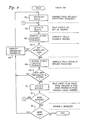
- FIG. 1 shows a high level block diagram of the debugging process.
- a debugging session using a preferred debugger is broken into three phases. These are a pre-consultation phase 24 , a consultation phase 26 , and a post-consultation phase 28 .
- the pre-consultation phase 24 the user can select the particular expert system (set of rules and variables) to be used.
- the user can program the inference engine 12 to operate in the forward-chaining or backward-chaining mode, and may display a static structure graph of the interrelationship between the variables and rules of the expert system, called a rule/variable network. Such a graph is described in more detail in connection with Figure 7 .
- the user may also examine the relationship between the rules and variables in the knowledge base 18 by invoking HOW and WHY explanation facilities. These facilities are described in more detail in connection with Figure 8 . If desired, the user can completely exit the debugger during the pre-consultation phase 24 . When a user is ready to observe the operation of the expert system, control is passed to the consultation phase 26 .
- the user may observe execution of the expert system.
- Selected breakpoints can be established which interrupt execution of the inference engine 12 when selected conditions, or sets of conditions, occur. Values of variables and rules may be changed during the consultation phase, and the inferencing steps used to set variables to their current values can be examined.
- the execution state of the inference engine can be rolled back to a prior intermediate state and execution restarted from such earlier point.
- the user may end the consultation phase 26 before any inferencing is performed, and return control to the pre-consultation phase 24 .
- This can be useful, if, for example, the user changes his mind about the rule set 14 to be used, or about whether forward or backward chaining should be used.
- the consultation phase 26 passes control to the post-consultation phase 28 when normal inferencing completes or when an explicit command to end consultation is given by the user while execution has been halted at a breakpoint.
- the user can access the various explanation facilities available during the consultation phase 26 .
- the user may also decide to reconsult or undo certain portions of the inferencing performed during the consultation phase 26, which has the effect of returning control to the consultation phase 26 and reinitiating the inferencing process.
- the user is allowed to exit the debugger from the post-consultation phase 28 .
- a block diagram illustrates flow of control within the consultation phase 26 .
- a pre-inferencing phase 30 is entered.
- control can be returned to the pre-consultation phase 24 .
- the user is able to access the general breakpoint processing commands described in more detail in Figure 8 .
- the user is allowed to define breakpoints which will halt execution of the inference engine 12 .
- the user is also allowed to specify whether inferencing will be performed in a normal execution mode, or in a single-step mode.
- Single-step mode causes the inference engine 12 to break to the debugger 20 after each inferencing event.
- Inferencing step 32 represents the actual inferencing performed by the inference engine 12 on the knowledge base 18 .
- control passes to the post consultation phase 28 .
- a significant inferencing activity occurs which causes a breakpoint condition to be reached, control is passed to a breakpoint processor 34 .
- the user is allowed to examine the status and history of the execution in the breakpoint processor 34 .
- breakpoint processing is complete, execution resumes and control is returned to the inferencing step 32 .
- Execution can be caused to proceed normally from the breakpoint, or single-step execution can be initiated from the breakpoint processor 34 .
- execution can be reinitiated from the beginning or rolled back to a prior intermediate state 36 when control is returned to the inferencing step 32 .
- the user is allowed to end the consultation prior to completing execution, causing control to be passed to the post-consultation phase 28 . Since variables and rules can be changed from within the breakpoint processor 34 , it is possible to place the consultation into an inconsistent state. In other words, if a variable value has been used during an inferencing step, and its value is now changed by the breakpoint processor, certain inferencing steps may need to be invalidated as being inconsistent with the current state of the knowledge base. If desired, the user can allow execution to proceed with an inconsistent state by returning control directly to inferencing step 32 . Preferably, in most cases, the recent inferencing activity will be undone and the knowledge base and inference engine reset to a consistent state 36 .
- Resetting the state 36 causes only as many inferencing steps to be undone as are required to back up to a point just prior to the point at which the changed variable or rule was first used. In many cases, this will be only a relatively short distance back into the inferencing process, and will be much more efficient than restarting the entire process from the beginning and redoing a large number of intermediate inferences.
- control is then returned to inferencing step 32 .
- inferencing steps can be undone from the post-consultation phase 28 , causing control to pass to the state reset step 36 .
- Figure 4 illustrates processing steps which occur within the inference engine 12 when it has been selected to operate in the backward-chaining mode. Also shown are various locations within the inferencing process during which breakpoints can be encountered. In a preferred embodiment, each time an inferencing activity occurs which could generate a breakpoint, a procedure call is made to a procedure within the debugger 20 which determines whether or not any breakpoint conditions are satisfied. If so, a breakpoint is generated and control passed to the breakpoint processor 34 . If not, control is returned to the inferencing process, which continues execution.
- An inferencing step begins by establishing goals 38 . At this point, one of the goals (variables) is not resolved. A breakpoint can be set to halt execution at this stage if a variable is selected as a goal. The next step is to activate a source 40 . This means that a rule is chosen as an active source in order to resolve a goal. A procedure call is made to the debugger in order to determine whether a breakpoint has been set for the condition that the chosen rule has been activated.
- the next step is to process the left hand side of the rule and evaluate its premises 42 .
- Variables contained on the left hand side of a rule may or may not actually be needed to process that rule, but a breakpoint can be set to halt execution when selected variables are found in the left hand side of an active rule.
- the next step is to determine whether any variables on the left hand side, which are needed in processing the active rule, are still unresolved 44 . If any remain unresolved, the unresolved variables required to process the rule are identified 46 and control is returned to step 38 to establish one of such variables as a goal.
- the left hand side of the rule is actually evaluated. Breakpoints can be generated at this time if the value of a variable is actually needed to evaluate the left hand side of the rule.
- a rule's premises After a rule's premises have been evaluated 48 , its actions are checked for references to unresolved variables 49 . If any references yet remain unresolved, the variables involved should be identified 46 and one of the unresolved variables selected as a goal 38 . Once the variables are resolved, breakpoints can be generated based upon whether or not the rule left hand sides are true or false. At this point, the actions on the rule's right hand side are executed 50 . A breakpoint can be defined to occur if the value of a selected variable changes at this stage.
- the next step is to determine whether any more sources remain 51 . If all sourcing activities for a selected variable have been completed 51 , the breakpoint corresponding to the variable's resolution may occur. If not, additional sources may be activated 40 . The entire process is repeated until there are no more unresolved goals 52 , at which time the inferencing process has come to an end.
- Figure 5 shows the inferencing activities performed by inference engine 12 when forward-chaining has been selected.
- the various breakpoints which may be selected are also shown.
- determination of whether a breakpoint has been reached is accomplished by performing a procedure call each time an inferencing activity is completed which can give rise to a breakpoint, and a comparison of the current state is made with the conditions of any defined breakpoints.
- the first step is to evaluate the premises of all rules that are affected by the initial data 54 .
- a breakpoint can be defined to occur based upon whether the value of the variable is possibly or actually needed.
- a breakpoint can also be generated when a rule is added to the conflict set.
- a breakpoint may be defined for a rule which is just about to be fired. The firing of a rule 62 may cause the value of one or more variables to change. Breakpoints can be defined to halt execution when a variable value is changed as a result of a rule firing.
- the effects of firing a rule are propagated to the rest of the knowledge base by identifying which rules are affected by the changed variables. This will cause the premises of affected rules to be reevaluated at step 54 . Once all the affected rules are identified as needing reevaluation in step 64 , any rule instantiation whose referenced variables have changed is removed from the conflict set. A breakpoint can be defined to occur when a rule is removed from the conflict set.
- the user can halt inferencing asynchronously.
- This can be implemented by having the user enter a break interrupt command from a keyboard or mouse input device.
- a procedure call is made to any debugger procedure in order to determine whether a breakpoint condition has occurred, a check is made to see whether a user has entered such a break command. If such is the case, the breakpoint processor is invoked just as if a predefined breakpoint had been reached.
- one of the functions which can be performed by the breakpoint processor is to roll back the execution of the system to a previous state. This may be needed when a rule or variable is changed which has already been used during execution in order to ensure consistent execution of the system. The user can roll execution of the system back to any desired state at any time.
- Figure 6(a) shows how information necessary for resetting the execution state is saved.
- Inferencing events 66 , 68 correspond to the events described in connection with Figures 4 and 5 . Only two inferencing events are shown in Figure 6(a) , although more will actually exist.
- Each inferencing event 66 , 68 is made up of a number of execution actions.
- the execution actions are atomic actions taken by the inference engine to perform its various activities.
- Inference event 66 is made up of execution actions 70 and 72
- inference event 68 is made up of execution action 74 and 76 .
- the number of execution actions necessary to perform a single inference event depends upon the event, and may vary from a single execution action to as many as are necessary to define a particular inference event.
- the records placed in queues 78 and 80 contain a complete description of the actions taken for each action and event. Each record placed into the queues can be removed, and its effects undone. In order to roll the system back to a prior state, it is necessary only to remove the appropriate number of records from the execution history queue 78 and inference history queue 80 in a last-in-first-out order. As each record is removed, its effects are undone, so that the execution history of the system progresses backwards through intermediate states.
- a set of debug queues 82 is preferably maintained by the system. Separate queues are maintained for each rule and each variable. Each time a variable is used or changed, an identifier of such event is added to its associated queue. Each time a rule is selected as a source in backward-chaining or added to the conflict set in forward-chaining, records are added to appropriate queues to identify when such events occurred and the variables which were involved in such selection. Whenever a rule fires, the values for all variables referenced in the clauses which were used to select that rule for firing are placed into the firing history queue for that rule.
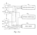
- Figure 6(b) illustrates in more detail the mechanisms by which information is saved to allow the state of the expert system to be rolled back.
- Inference engine 12 is preferably implemented as a state machine inference engine 150 . This is a state machine which continuously loops through a fairly simple execution cycle. During each cycle, the inference engine 150 pops a record off of an execution stack 152 , and adds a copy of the record to the execution history queue 78 . The record added to the execution history queue 78 contains a current value of a counter which is incremented each time the execution cycle is performed. Therefore, the execution history queue 78 will contain a sequence of consecutively numbered records representing a history of the records which occurred on the top of the execution stack 152 .
- Each record on the execution stack 152 contains information identifying the current state in which the inference engine 150 should be.
- the inference engine 150 calls the necessary code to perform activities associated with that state.
- the code for each execution state examines the values of relevant information, makes any changes which are required, and computes the next state which should be entered.
- a record for the next execution state is then pushed onto the execution stack, and the cycle completes.
- Typical execution states for the inference engine 150 include "check rule premise,” “fire rule consequent,” “obtain value,” “add to conflict set,” and “remove from conflict set.” These execution states correspond to the atomic actions 70 , 72 , 74 , 76 described in connection with Figure 6(a) .
- the forward-chaining and backward-chaining inference processes are also preferably modelled as finite-state machines. Each process consists of a cycle of inferencing states, each of which in turn can be performed by performing a sequence of execution states.
- the inference states corresponds to states 66 and 68 of Figure 6(a) .
- Typical inference states include "match,” “execute,” “obtain value,” and "fire rule.”
- the number of execution states needed to perform a single inference state depends upon the complexity of the actions needed to perform the inference state. For example, the "match" state of the match-execute cycle in the forward-chaining process is made up of a number of "check rule premise" and "add to conflict set” execution states.
- the number required during execution depends upon the number and values of the terms in the left hand side of a particular rule.
- the firing of a rule in the forward-chaining process involves two execution states, "remove from conflict set” and "fire rule consequent.”
- the firing of a rule in the backward-chaining process also preferably involves two states: “check rule premise” and "fire rule consequent.”
- an inference state is pushed onto the inference stack 154 .
- a record is popped from the inference stack and copied to the inference history queue 80 in much the same manner as execution records are copied to the execution history queue 78 .
- Each inference record copied to the inference history queue 80 contains a time stamp indicating the current execution state number in the same manner as is stored with the execution records in the execution history queue 78 .
- a call is made to a breakpoint procedure to determine whether a breakpoint has, in fact, been encountered.
- a record is placed into a breakpoint queue 156 .
- the record placed into the breakpoint queue 156 indicates the current execution state number at the time it is placed onto the queue 156 .
- the record also indicates the type of breakpoint for which it is being generated. For example, if a potential rule firing breakpoint is reached, this fact is identified on the record placed into the breakpoint queue 156 .
- a complete history of all changes made to the variables 16 is retained in a version history queue associated with each variable. This history is in addition to the debug queue history which indicates when a variable was used, when it became a goal, etc.
- a record is added to the associated version history queue which includes the new value of the variable and the current execution state number. As above, the execution state number functions as a time stamp to indicate when the various variables changed value.
- a rule history queue is associated with each rule 14 . Each time a rule is used during an execution state, an associated record is placed in the rule history queue for that rule. As before, the current execution state number is used as a time stamp.
- Each set of various kinds are often utilised during execution of that expert system. These sets are collections of elements which may be modified from time to time.
- the inference engine 150 accesses such sets 158 , and adds a record to a set history queue 160 each time the set is modified.
- each record in the set history queue 160 an contain either a complete copy of the modified set 158 , or can include only a listing of all of the elements which were added to and deleted from the set 158 .
- An example of such a set 158 is the conflict set used in forward-chaining. As rules are added to or removed from the conflict set, this activity is reflected in the set history queue 160 . As occurs in the cases described above, the current execution state number is used as a time stamp for each record added to the set history queue 160 in order to provide a time history for activities performed on that set.
- the execution stack 152 is rebuilt by running the inference engine 150 in reverse. All stack operations to the execution stack 152 are inverted, so that previous pushes to the execution stack 152 cause a record to be popped, and previous pops cause the last record in the execution history queue 78 to be pushed onto the execution stack 152 . This reverse process continues, with the execution state number decreasing as each execution state is retrieved from the history queue 78 and pushed onto the stack 152 , until the desired execution state number has been reached.
- a similar process is performed on the inference stack 154 and for each set 158 .
- the execution state number during the reverse process is equal to the execution history number stored with the last record on each of the inference history queue 80 and set history queue 160 , that record is removed from the queue.
- the records are placed onto the inference stack 154 .
- the associated set 158 is updated according to the values stored in the set history queue record.
- Each version history queue is simply scanned for the latest version having a time stamp less than or equal to the execution state number to which the roll back is being performed. All versions having a later time stamp are simply discarded.
- the history queues for the various rules 14 are rolled back in the same manner as the variable version history queues.
- the breakpoint queue 156 can also be rolled back by simply discarding all records on the queue later than the selected roll back point. However, the breakpoint queue 156 can be gainfully put to use for another purpose. It can be used to define roll back states in much the same manner as breakpoints are defined when the inference engine 150 is executing in the forward direction. For example, in forward-chaining, a reverse breakpoint could be defined as the time when a rule is added to the conflict set, or removed therefrom. The breakpoint queue is then scanned from the end toward the beginning, with checks being made at each possible breakpoint. For the above example, the set history queue 160 would be checked for the conflict set at each possible related breakpoint and a quick determination made as to when the desired breakpoint is actually reached in the reverse direction. Once that breakpoint has been identified, the corresponding execution state number is identified and the remainder of the system rolled back to that execution state.
- the debugger allows the user to modify variable values at a breakpoint. This can place the inference engine into an inconsistent state, inasmuch as the previous value of that variable may have already been used in earlier inferencing steps. In many cases, it would be desirable to roll the inference engine back to a state which is consistent with all of the changes made during the breakpoint session, and restart execution from there.
- the roll back mechanism just described can be used to reset the expert system to any earlier state once a previous consistent state has been identified. A technique will now be described for determining such a last consistent state when roll back to a consistent state is desired.
- Smarter techniques result in a shorter roll back, but require more computational resources to determine the appropriate execution state to which the roll back should be performed.
- the first approach is, in effect, the same as that used by prior art expert system debuggers. This approach is to restart the entire consultation from the beginning whenever a change is made to a rule or variable during a debugging session. In many cases, this would require the performance of a large amount of redundant computation, since the change which has been made may have no effect upon execution of the expert system until immediately prior to the breakpoint at which its value was changed.
- the next approach is to go back to the earliest time at which a changed variable or rule could have been used. In the preferred system, this is the approach used whenever a change is made to a variable.
- variable was ever a goal. This can be determined by scanning the debug queue for the variable from the beginning, looking for a record indicating that the rule was selected as a goal. If the variable was ever selected as a goal, the immediately proceeding execution state is the last consistent state to which the inference engine must be returned.
- the earliest point at which the changed rule could he been used is the earliest point at which it could have entered the conflict set. Determining this point preferably includes the determination of minimal firing sets for the changed rule. For many rules, it is not necessary for all variables on the left hand side to be defined before that rule can fire. For example, in a rule having a left hand side of the form: (A and B) or (C and D) it is possible for the rule to fire when only A and B are defined, and also when only C and D are defined. Thus, A and B together form an element in a minimal firing set for the rule, as do C and D together.
- a fourth approach is similar to that just described, but also involves actually looking at the values of the variables involved on the left hand side, and determining whether the variable values actually cause the left hand side to enter the conflict set. Although such determination can result in a later calculated consistent state, requiring less roll back to be performed, it is significantly more complex than the determination just described and is not therefore preferred for reasons of efficiency. In certain systems, depending upon the values of the various variables and the structure of the rules, significant savings can be realised by performing the more complex testing. In such systems, using variable values to determine the last consistent state after a rule is changed could be justified.
- the histories of the various variables and rules can be used to trace the changes which occur in variables and the points at which rules were used. This allows the user to step back through the history of a selected rule or variable one step at a time in order to determine the causes of errors.
- a debugging tool which is preferably provided by the preferred embodiment is a graphical display of a rule/variable network.
- An example of a simple such display is shown in Figure 7(a) .
- Figure 7(a) is a graphical representation of a knowledge base having four rules 84 , 86 , 88 , 90 and nine variables 92 - 108 .
- Variables used in a rule's condition are connected to the left hand side of the rule box, and variables about which conclusions are made in a rule's action are connected to the right hand side of the rule.
- rule 84 uses variables 92 and 94 to draw a conclusion about variable 102
- rule 88 uses variables 98 and 100 to draw conclusions about variables 96 and 106 .
- the network of Figure 7(a) is used in each of the pre-consultation, consultation, and post-consultation modes. Use of the network varies somewhat depending on which mode the system is in.
- the static rule/variable network as shown in Figure 7(a) is used in the pre-consultation mode to illustrate the static dependencies between the various rules and variables in the knowledge base. This can be utilised by the user to determine which rules will be affected by changing various variables, and which variables will be affected by changing various rules.
- a form of animation is provided for the rule/variable network to indicate visually the progress of events within the inferencing process.
- various indicia can be used to illustrate graphically the progression of the inferences performed by the expert system.
- Changes in colour or shading can be used to indicate the status of the rules and variables. If a colour display is provided, changes in colour can be provided for the graphical elements representing the rules and variables. If a monochrome display is provided, changes in shading can be used.
- FIGS 7(b) - 7(i) illustrate a preferred scheme for representing changes in a monochrome graphical display.
- Each variable node 162 within the rule/variable network has a corresponding offset variable node 164 .
- the offset variable node 164 is partially obscured by the overlying variable node 162 , and is used only to help indicate status changes of the variable node 162 .
- Each rule node 166 also has an offset rule node 168 which functions in a similar manner.
- hatching in a single direction indicates that a node is coloured gray, while cross-hatching indicates that a node is coloured black on a monochrome display.
- variable node 162 and offset variable node 164 are black for every variable in the network. This situation is shown in Figure 7(b) . Assuming backward chaining is being used by the inference engine, the offset variable node 164 becomes gray whenever the variable it represents is selected as a goal. This is illustrated in Figure 7(c) . When a variable receives a value, the variable node 162 is also coloured gray as shown in Figure 7(d) . When the variable is resolved, the variable node 162 remains gray and the offset variable node 164 becomes white as shown in Figure 7(e) .
- the rule nodes 166 and offset rule nodes 168 are also black initially as shown in Figure 7(g) .
- the offset rule node 168 becomes gray while the rule node 166 remains black as shown in Figure 7(h) .
- the rule node 166 also becomes gray as shown in Figures 7(i) .
- a similar animation technique is used when the underlying inference engine is performing forward-chaining. Variables do not become goals in forward-chaining, so no offset variable node is used. When a variable is assigned a value, a variable node 169 turns from black to gray, resulting in the display shown in Figure 7(f) . In the forward-chaining case, the offset rule node 168 becomes gray when a rule enters the conflict set, giving the display shown in Figure 7(h) , and the rule node 166 turns gray when the rule is fired as shown in Figure 7(i) .
- Some variables have values initially assigned to the knowledge base.
- the nodes corresponding to these variables are initially assigned the graphic values used for variables which receive values.
- the offset variable node 164 will be white while the variable node 162 is gray.
- the offset variable node 164 will initially be black and the variable node 162 is gray.
- An animated display such as described above allows a user to observe the general flow of the inferencing process without being confused by the many details which occur at each step. If the inferencing process starts to take a direction which the user knows is incorrect, he can asynchronously interrupt execution and determine the cause of the problem.
- the rule/variable network will statically display the final status of all the rules and variables in the knowledge base.
- the user is able to view graphically which variables were used as goals and received values, and which rules were fired.
- a variable will be involved in a cycle. For a backward-chaining inference engine, this occurs when a variable is found on the left hand side of a rule used in a subgoal for resolution of that variable.
- a cycle would occur in Figure 7(a) if, for example, the nodes for VAR4 98 and VAR7 104 actually represented the same variable.
- the usual round node 162 is placed to the right in the rule/variable network to indicate that it is a goal, and a diamond-shaped symbol is used to indicate a split variable node 170 .
- the round node 169 is shaded as the offset node 164
- the diamond shaped node 170 is shaded as the variable node 162 .
- the same display technique is used in the forward-chaining case.
- a procedure call is also made to a display manager to change the appropriate node of the display. Changes are made to the display regardless of whether or not a breakpoint is actually defined to occur at that time.
- Figure 8 illustrates a diagram of the various events which can occur when the breakpoint processor 34 is invoked at a breakpoint.
- the condition which caused execution of the inference engine to halt is displayed 110 for the information of the user.
- the breakpoint processor then gets an input from the user 112 , and performs one of a variety of actions depending upon the user's selection.
- the user is allowed to view and edit the breakpoints 114 which will halt execution of the inference engine.
- a menu can be presented to the user to allow him to add, edit, and delete multiple breakpoints at one time.
- the user may also elect to view and edit the rules 116 within the knowledge base, or to view and edit the variables 118 . If a user edits a rule or variable which has been used, a consistency analysis is preferably performed automatically by the system. A preferred method for checking consistency was described above. If the change puts the system into an inconsistent state, the user is signaled. The user will have the opportunity to roll execution back to a consistent state if desired.
- the user may perform a detailed rule trace 120 , which presents detailed information about a particular rule firing. Namely, the values of all variables referenced and the truth values for each premise condition are shown. This level of detail is not provided by prior art explanation facilities, but is necessary for debugging.
- the user can elect to be shown why a variable value is needed 122 , or how a value was obtained 124 .
- the WHY inquiry 122 displays the reasons that the control procedure (forward or backward chaining) might need a value for a particular variable, or how that variable's value might ripple through the various rule and variable interactions.
- the HOW inquiry 124 displays how the control procedure would go about trying to determine a value for a particular variable.
- the WHY inquiry is essentially a forward looking question, and asks "why do I need this information?"
- the HOW command is essentially a backward looking question, and asks "how did things get to be this way?"
- both the HOW and WHY inquiries can be used to determine both past and future usages for a rule or variable.
- the WHY inquiry 122 shows where a variable has been used (past) and where it might yet be used (future).
- the debug queues are used to obtain the past information, while the static rule/variable network is used for future case, just as occurs during the pre-consultation phase.
- the HOW inquiry 124 also uses the debug queues to obtain the past information showing how a variable received its current value or a rule was caused to fire.
- the HOW inquiry 124 relies on the static rule/variable network to answer queries regarding events that have not yet occurred, in a manner similar to the WHY inquiry 122 .
- the HOW and WHY inquiries can be used only to find the possible steps which might be taken by the inference engine.
- the user may choose to exit the breakpoint processor 34 in several different ways.
- the user may begin or continue single step execution 126 of the inference engine. Control will return to the breakpoint processor 34 after a single step is completed.
- the user may end the consultation phase prematurely, and go directly to the post-consultation phase 128 .
- the user may also cause an exit from the breakpoint processor and a return to normal execution 130 , or may cause the system to restart execution from the very beginning 132 .
- the execution state may be rolled back 134 to a selected state or one defined by a reverse breakpoint. This will often be done after the consistency analysis 119 indicates that a change has introduced an inconsistency, and the option of rolling back directly to the last consistent state is provided to the user.
- the rule-based debugger described above allows a user to obtain detailed information about the progress of the expert system program. Breakpoints can be set and changed dynamically, and changes can be made to rules and variable values in order to observe the effect of such changes on the overall execution of the system.
- the same debugger can be used to support both forward-chaining and backward-chaining on a knowledge base, and consistent interactions with the user are used in both cases.
- Detailed information regarding the history of the execution is available to the user in several forms, and the execution state can be rolled back to a previous intermediate state. This latter capability allows changes to be made to rules and variables without requiring that inferencing be restarted from the very beginning.
- the debugger described above can be used with such an expert system. It is designed to provide useful debugging information when the ordering of events is not known in advance. Since this situation is encountered in parallel processing systems, generally, the debugger described above can be used, with proper modifications, with such systems. Breakpoints can be defined for each process separately, and the debugger is invoked when one of them is reached. Depending on the system design, remaining processes can also be halted or can continue.
- a tool analogous to the rule/variable network can be used to illustrate graphically the relationships between processes using messages or shared variables. The ability to examine the execution history of the various processes is useful for debugging parallel systems in much the same manner that it is useful for debugging rule-based systems.
Landscapes
- Engineering & Computer Science (AREA)
- Theoretical Computer Science (AREA)
- Physics & Mathematics (AREA)
- General Physics & Mathematics (AREA)
- General Engineering & Computer Science (AREA)
- Computing Systems (AREA)
- Evolutionary Computation (AREA)
- Data Mining & Analysis (AREA)
- Computational Linguistics (AREA)
- Mathematical Physics (AREA)
- Software Systems (AREA)
- Artificial Intelligence (AREA)
- Quality & Reliability (AREA)
- Debugging And Monitoring (AREA)
- Control Or Security For Electrophotography (AREA)
Applications Claiming Priority (2)
| Application Number | Priority Date | Filing Date | Title |
|---|---|---|---|
| US47083190A | 1990-01-26 | 1990-01-26 | |
| US470831 | 1990-01-26 |
Publications (2)
| Publication Number | Publication Date |
|---|---|
| EP0449402A2 true EP0449402A2 (de) | 1991-10-02 |
| EP0449402A3 EP0449402A3 (en) | 1993-05-12 |
Family
ID=23869231
Family Applications (1)
| Application Number | Title | Priority Date | Filing Date |
|---|---|---|---|
| EP19910300517 Withdrawn EP0449402A3 (en) | 1990-01-26 | 1991-01-23 | Method for rolling back an expert system |
Country Status (2)
| Country | Link |
|---|---|
| EP (1) | EP0449402A3 (de) |
| JP (1) | JPH0772866B2 (de) |
Cited By (2)
| Publication number | Priority date | Publication date | Assignee | Title |
|---|---|---|---|---|
| US5903885A (en) * | 1995-09-27 | 1999-05-11 | U.S. Philips Corporation | Data processing apparatus event cause determination |
| GB2418755A (en) * | 2004-10-04 | 2006-04-05 | Agilent Technologies Inc | Error handling using a structured state tear down |
Families Citing this family (2)
| Publication number | Priority date | Publication date | Assignee | Title |
|---|---|---|---|---|
| JP4390858B2 (ja) * | 1996-10-04 | 2009-12-24 | フィッシャー コントロールズ インターナショナル リミテッド ライアビリティー カンパニー | 分散型制御機能を有するプロセス制御ネットワークをデバッグし、チューニングする方法および機器 |
| JP2005165600A (ja) * | 2003-12-02 | 2005-06-23 | Nec Corp | トランザクション処理システム、トランザクション処理方法およびプログラム |
Citations (1)
| Publication number | Priority date | Publication date | Assignee | Title |
|---|---|---|---|---|
| EP0163096A1 (de) * | 1984-04-26 | 1985-12-04 | BBC Brown Boveri AG | Einrichtung zur Rettung eines Rechnerzustandes |
Family Cites Families (1)
| Publication number | Priority date | Publication date | Assignee | Title |
|---|---|---|---|---|
| JPH01251237A (ja) * | 1988-03-31 | 1989-10-06 | Toshiba Corp | 推論システム |
-
1990
- 1990-12-26 JP JP2406911A patent/JPH0772866B2/ja not_active Expired - Lifetime
-
1991
- 1991-01-23 EP EP19910300517 patent/EP0449402A3/en not_active Withdrawn
Patent Citations (1)
| Publication number | Priority date | Publication date | Assignee | Title |
|---|---|---|---|---|
| EP0163096A1 (de) * | 1984-04-26 | 1985-12-04 | BBC Brown Boveri AG | Einrichtung zur Rettung eines Rechnerzustandes |
Non-Patent Citations (2)
| Title |
|---|
| IBM TECHNICAL DISCLOSURE BULLETIN. vol. 31, no. 5, 10 October 1988, NEW YORK US pages 151 - 154 , XP34949 'Visual debugger for Prolog' * |
| IECON '89. 15TH ANNUAL CONFERENCE OF IEEE INDUSTRIAL ELECTRONICS SOCIETY vol. 4, 6 November 1989, PHILADELPHIA US pages 715 - 720 , XP130578 A. NAKAMURA ET AL.: 'Display monitor intelligent adjusting system: DIAS' * |
Cited By (3)
| Publication number | Priority date | Publication date | Assignee | Title |
|---|---|---|---|---|
| US5903885A (en) * | 1995-09-27 | 1999-05-11 | U.S. Philips Corporation | Data processing apparatus event cause determination |
| GB2418755A (en) * | 2004-10-04 | 2006-04-05 | Agilent Technologies Inc | Error handling using a structured state tear down |
| US7246276B2 (en) | 2004-10-04 | 2007-07-17 | Agilent Technologies, Inc. | Error tolerant modular testing of services |
Also Published As
| Publication number | Publication date |
|---|---|
| EP0449402A3 (en) | 1993-05-12 |
| JPH0689177A (ja) | 1994-03-29 |
| JPH0772866B2 (ja) | 1995-08-02 |
Similar Documents
| Publication | Publication Date | Title |
|---|---|---|
| US5140671A (en) | Expert system debugger | |
| US5170464A (en) | Method for rolling back an expert system | |
| US5167012A (en) | Method for performing consistency checks | |
| US5297150A (en) | Rule-based method for testing of programming segments | |
| US5535389A (en) | Business process objects with associated attributes such as version identifier | |
| US5838975A (en) | Method for testing and debugging computer programs | |
| EP0413485B1 (de) | Leistungsverbesserungsgerät für auf Regeln beruhendes Expertensystem | |
| US5402526A (en) | Interruptibility/priority control scheme for artificial intelligence software shell | |
| US8336032B2 (en) | Implementing enhanced template debug | |
| US5598511A (en) | Method and apparatus for interpreting data and accessing on-line documentation in a computer system | |
| JPH05197556A (ja) | エキスパート・システム及びエキスパート・システムのエキスプラネーシヨン発生方法 | |
| JP2005527916A (ja) | 作業リスト予報のためのシステムおよび方法 | |
| US5398304A (en) | Control process for artificial intelligence software shell | |
| JP2814691B2 (ja) | 推論方法に基づく故障診断方法 | |
| EP0439343A2 (de) | Verfahren um ein Expertensystem zu betreiben und Rechnersystem dafür | |
| Teitelman | Automated programmering: the programmer's assistant | |
| Montanari et al. | Contextual occurrence nets and concurrent constraint programming | |
| US5072405A (en) | RETE network with provisional satisfaction of node conditions | |
| EP0449402A2 (de) | Verfahren um ein Expertensystem zurückzuspulen | |
| Schroeder et al. | Distributed diagnosis by vivid agents | |
| EP0439342A2 (de) | Betriebsverfahren von einem Expertensystem und Rechnersystem dafür | |
| EP0439341A2 (de) | Bilddarstellung für ein Expertensystem | |
| US5390286A (en) | Reticular discrimination network for specifying real-time conditions | |
| Bauer | A Basis for the Acquisition of Procedures from Protocols | |
| Hale et al. | Towards a model of programmers' cognitive processes in software maintenance: A structural learning theory approach for debugging |
Legal Events
| Date | Code | Title | Description |
|---|---|---|---|
| PUAI | Public reference made under article 153(3) epc to a published international application that has entered the european phase |
Free format text: ORIGINAL CODE: 0009012 |
|
| AK | Designated contracting states |
Kind code of ref document: A2 Designated state(s): DE FR GB |
|
| 17P | Request for examination filed |
Effective date: 19911112 |
|
| PUAL | Search report despatched |
Free format text: ORIGINAL CODE: 0009013 |
|
| AK | Designated contracting states |
Kind code of ref document: A3 Designated state(s): DE FR GB |
|
| STAA | Information on the status of an ep patent application or granted ep patent |
Free format text: STATUS: THE APPLICATION HAS BEEN WITHDRAWN |
|
| 18W | Application withdrawn |
Withdrawal date: 19960923 |