EP0448610B1 - Process and installation for the control of electro-mechanical converters - Google Patents
Process and installation for the control of electro-mechanical converters Download PDFInfo
- Publication number
- EP0448610B1 EP0448610B1 EP90900794A EP90900794A EP0448610B1 EP 0448610 B1 EP0448610 B1 EP 0448610B1 EP 90900794 A EP90900794 A EP 90900794A EP 90900794 A EP90900794 A EP 90900794A EP 0448610 B1 EP0448610 B1 EP 0448610B1
- Authority
- EP
- European Patent Office
- Prior art keywords
- dependent
- transformer
- moment
- instantaneous values
- rotation
- Prior art date
- Legal status (The legal status is an assumption and is not a legal conclusion. Google has not performed a legal analysis and makes no representation as to the accuracy of the status listed.)
- Expired - Lifetime
Links
Images


Classifications
-
- G—PHYSICS
- G01—MEASURING; TESTING
- G01R—MEASURING ELECTRIC VARIABLES; MEASURING MAGNETIC VARIABLES
- G01R31/00—Arrangements for testing electric properties; Arrangements for locating electric faults; Arrangements for electrical testing characterised by what is being tested not provided for elsewhere
- G01R31/34—Testing dynamo-electric machines
- G01R31/343—Testing dynamo-electric machines in operation
Definitions
- the invention relates to a method for controlling electromechanical transducers for the purpose of generating a predetermined force or torque curve, in particular for reducing angle-dependent torque fluctuations in electric motors, in which time-dependent or position-dependent (path or angle of rotation-dependent) data records are stored in a function memory and are dependent on distance or angle of rotation traveled during operation, or called up in a timed manner and linked in an arithmetic circuit unit with an input variable to instantaneous values, and in which, depending on the instantaneous values, voltages or currents with a corresponding time- or position-dependent curve shape into the electrical connections of the converter.
- an arrangement for performing such a method is the subject of the present invention.
- an electric motor is its concentricity (or the uniform force curve of an electromechanical converter). It affects both the accuracy and the stability of a drive system. In order to suppress the disturbing torque pulsations in motors, the cause must first be localized.
- Four factors are essentially responsible for the torque fluctuations: Even when the armature is de-energized, permanent magnetic torque fluctuations can occur in motors with permanent magnetic excitation or in motors with iron parts with high remanence induction, triggered by the interaction between the permanent magnetic materials and the winding slots or other ferromagnetic parts.
- a rotation of the rotor leads to fluctuations in the total energy of the magnetic circuit and thus to angle-dependent torques with alternating stable and unstable extreme values.
- the electromagnetic torque fluctuations result from the interaction between the armature current coating and the magnetic field.
- the electromagnetic fluctuations are a result of the special magnetic field distribution in the air gap, the winding arrangement and the armature current curve shape depending on the rotor angle.
- Torque pulsations in the motor can also have mechanical causes.
- the mechanical torque fluctuations are triggered, for example, by asymmetrical tensioning of the motor shaft, such as axis misalignment in couplings, eccentric bearing seats, etc. They can also result from the load coupled to the motor (or converter in general).
- the proportion of permanent magnetic torque fluctuations can be eliminated, for example, by using an ironless winding combined with a ring-shaped iron yoke (example: bell-armature motors).
- a ring-shaped iron yoke example: bell-armature motors
- a strong one Reduction is achieved by tapering the iron sheet stack, for example by a groove division, as well as by a suitable design of the magnet shape and the groove, tooth or pole shoe geometry.
- Drive motors that are designed for stationary speeds are often equipped with an additional flywheel (e.g. turntable).
- the electromagnetic pole sensitivity can be structurally influenced, for example, by a choice of the winding design adapted to the air gap field and the current curve, and thus also by an inclination of the slot pitch.
- the reluctant torque fluctuations can be greatly reduced, among other things, by using rotationally symmetrically arranged soft and hard magnetic materials.
- Another possibility to improve the synchronization is the electrical compensation of the torque pulsations.
- one provides automatic control device for improved synchronization, run-up or positioning.
- the demands placed on the controller for adaptive control parameters, speed and stability cannot always be met satisfactorily with this method. It is therefore advisable to relieve the controller of the regulation of the pendulum torques and to generate the current harmonics required for constant torque based on a characteristic curve that was determined in advance from the motor data.
- a method that is frequently used in brushless DC motors is to vary the ratio of the on and off area of the square-wave control.
- an improved synchronization characteristic is achieved (references 1 to 3).
- the present invention is based on the object of proposing a method and an arrangement for controlling electromechanical transducers for the purpose of generating a predetermined force or torque curve, in which all, at least the most important and most evident, relate to the force or torque curve components and possibly also other disturbance variables in other directions are taken into account, in particular in order to achieve good concentricity in electric motors, no structural measures having to be taken on the motor for this purpose.
- the method according to the invention have the advantage that there is a simpler construction of the converter with lower tolerance requirements, and that in the event of a reduction in the position-dependent force and torque fluctuations in electric motors, noise is reduced and special flywheels in the drives can be eliminated .
- the data sets that take into account the force or torque curve of the converter and, if applicable, the load can either be calculated from the given construction and material data, or they are calculated indirectly from parameters and / or characteristic curves measured on a sample. In the first case, no test bench is required, and no other measurements are required.
- An expedient arrangement for carrying out the method according to the invention is characterized by a functional memory with one memory section for each influence to be taken into account for storing the assigned data record, an arithmetic circuit unit for linking data records read from the memory sections with at least one input variable and for combining the linking results into instantaneous values , a position or timer assigned to the electromechanical transducer for controlling the position or time-dependent reading of the data in the functional memory, and a power controller for impressing voltages or currents into the electrical connections of the transducer in accordance with the instantaneous values.
- a multi-phase converter e.g. a multi-phase electric motor
- data records can be stored for each of the individual phases and corresponding instantaneous values can be derived therefrom, corresponding function memories, arithmetic circuit units and power controllers or corresponding sections being provided for each of the phases, or these being operated in time-division multiplex.
- asymmetries and other deviations between the individual phases of the converter can be taken into account.
- electromechanical transducer is understood to mean any transducer which produces a mechanical effect from an electrical current or a voltage or vice versa, e.g. electromagnetic transducers, piezoelectric transducers, electrical transducers, thermal transducers. Of particular importance are rotating electric motors and generators (ideal brake) as well as linear motors, but also loudspeaker drive systems, relays, actuators and pulling magnets.
- the first term of the torque equation contains the electromagnetic torque component. It is determined by the interaction between the magnetic coil fluxes and the associated armature currents.
- the electromagnetic component consists of a constant useful torque and a superimposed pulsation torque.
- the second term from the torque equation describes the reluctance torque.
- a change in the motor inductance as a function of the angle leads, in conjunction with the armature currents, to a resulting moment which, depending on the supply and design, consists of a constant useful torque and pulsation torque.
- the third term from the torque equation shows the permanent magnetic and the mechanical part. Due to the interaction between armature grooves and permanent magnets, this generates cogging moments and thus disturbing pulsations.
- the size of these four components is influenced by the principle and the engine design.
- phase voltage characteristic for one phase of the motor is shown in FIG. 3.
- the induced voltages were recorded at a very high speed (5000 rpm), so that disturbances due to speed fluctuations are negligible. If these measurements have to be made at lower speeds, an additional flywheel would be required. If this motor is fed with the phase current curves determined according to the flow diagram according to FIG. 2, the torque curve is very uniform without fluctuations. Any residual disturbances can be detected by a measurement and eliminated by appropriately adapted current curves in a second step or in additional subsequent steps.
- the ordinal number of the current harmonics is determined so that they interact with the largest voltage harmonics (basic harmonics).
- the disturbance torques that arise from the interaction of the calculated current harmonics with voltage components, the atomic number of which Fundamental harmonics deviate, are calculated and eliminated step by step through an iterative correction process.
- the permanent magnetic cogging torque from the torque equation (Eq. 1-15) is a function of the rotor angle ⁇ .
- T r T r ( ⁇ ); (3 -1)
- this part is independent of the current.
- the torque curve can be determined via a field calculation or directly via a measurement.
- the route via the (numerical) field calculations sometimes leads to very uncertain results.
- the effects of these effects are directly included in a torque measurement. Two methods are available for torque measurement:
- the derivation of the system of equations for the compensation of the permanent magnetic and mechanical torque component begins with the representation of the dynamic equation of motion for the measuring system according to FIG. 5.
- the drive servo motor is controlled via a controllable voltage source in such a way that the permanent magnetic tilting moments of the currentless test motor are just overcome at the lowest possible speed will.
- the torque that occurs can be measured in the steady state via the armature current of the drive motor.
- T f (I ( ⁇ )); (3 -2)
- the measurable torque consists of three components, which are considered below.
- the cogging torque T r is triggered by a superimposition of the permanent magnetic torque fluctuations, the mechanical torque fluctuations and the speed-independent friction torque component.
- T 2 ( ⁇ ) can depend linearly or strongly non-linearly on the speed. Influencing variables are bearing and brush friction, air friction, eddy current and hysteresis braking torques.
- the current curve can alternatively be determined on the basis of a harmonic analysis.
- phase current curves can be seen from the flow diagram according to FIG. 6 (with the parts of FIGS. 6a, 6b and 6c).
- the measurements on the engine required for the calculation are carried out fully automatically on a measuring and test stand, so that the engine can then be operated and tested with the determined correction curve.
- FIG. 7 shows, for a motor phase, the current curve determined in the iterative method according to the flow diagram according to FIG. 6 in a standardized form for the compensation of permanent magnetic and mechanical torque fluctuations.
- 8 and 9 show curves for the standstill torque before and after the electronic correction.
- 10 now shows an exemplary embodiment in a schematic representation of an arrangement for actuating electromechanical converters, in the present case an electric motor.
- 10 contains a motor controller 10, an arithmetic circuit unit 20, a function memory 30 and a power supply for the motor 3, which in the present example consists of a current controller 5, an output stage 6, a DC voltage supply 7 and a current measuring device 4.
- the arithmetic circuit unit contains two multipliers 21 and 22 and a logic circuit in the form of an accumulator (summer) 23, the output signal of which controls the current regulator 5.
- the function memory 30 contains two curve memories 31 and 32 in the present case, so that two different terms can be taken into account. Should other terms, e.g. B.
- the arithmetic circuit unit 20 and the functional memory 30 are still to be expanded by the corresponding elements.
- the links may not be multiplicative and additive, as shown in Fig. 10, but if necessary by corresponding other functional links.
- each of the memory sections can be divided into several parts so that different data records can be stored for each influencing variable. These different data records are then selected by an input variable 33.
- the motor controller 10 contains a torque control 11, a speed controller 12 and a position controller 13, the output signals of which are optionally applied to an input 25 of the arithmetic circuit unit 20 via a changeover switch, as well as a speed and direction of rotation detection 14.
- a changeover switch as well as a speed and direction of rotation detection 14.
- an input 24 is provided for the arithmetic circuit unit.
- the motor 3 is coupled to an angle encoder 2 in order to deliver corresponding angular position signals both for the function memory 30 and for the motor controller 10.
- Input variable 33 decides on the selection of special curves to take various operating states into account (non-linear operation due to iron saturation and armature reaction, temperature ) and motor operating modes (e.g. uniform operation or pulsating operation as stepper motor).
- the following input variables are of interest for the circuit arrangement: manipulated variables for the amplitudes of the stored nominated curves or the curve generator, possibly a signal variable which enables the curves to be read out depending on the time or depending on the rotor position, control or signal variables for selecting the curves and possibly for changing the curves Curve shape especially with non-linear motor characteristics, where the curve shape has to be adjusted according to the operating state.
- control variables for an arithmetic circuit unit 20 can also occur, for example, which control the sequence of the linking of manipulated variables and curves or change the linking function in accordance with the operating state of the engine.
- the output variables are digital, analog or other signal quantities which, if necessary, impress the motor phases via a power controller, defined currents or voltages in order to improve the concentricity of the motor or the operating characteristics in general.
- the data for curves which lead to the compensation of the individual types of torque fluctuations are stored in the function memory 30.
- the data can be saved in the form of tables, regulations (e.g. limitation of the maximum current amplitude), equations or functions.
- regulations e.g. limitation of the maximum current amplitude
- equations or functions e.g. limitation of the maximum current amplitude
- the function memory 30 can also be replaced by curve generators which generate the defined curves.
- An arithmetic circuit unit 20 now links the curve amplitudes provided as a function of time or rotor angle to the input manipulated variables according to defined functions.
- the current curve values calculated for a rotor revolution of the individual phases for reducing the electromagnetic torque fluctuation (curve memory 32) and the permanent magnetic including the mechanical fluctuation (curve memory 31) are separated and stored in standardized form.
- the current curve of the curve memory 31 is read out in accordance with the rotor angle ⁇ and multiplied by a current amplitude i A (input 24).
- the amplitude i A is chosen so that the permanent magnetic torque fluctuations are minimal.
- the amplitude i A is also contained in the stored data set. For motors with an unsaturated iron circuit and negligible armature reaction, the amplitude can be kept constant. Otherwise, the value must be updated according to the circumstances.
- the current curve generated in this way flows unchanged into the individual phase windings, regardless of the operating state of the motor and thus compensates for the permanent magnetically and mechanically caused torque pulsations.
- a third path or further paths consisting of an additional memory section and a logic element (not shown), can be added to the circuit according to FIG. 10, which the Reduction of the reluctant fluctuations allowed by appropriate current profiles.
- the electrical circuit can be implemented in various ways. For example, it can be constructed purely in terms of hardware from analog and / or digital modules, or it can also be implemented in software using a computer program.
- a torque control as well as a position, speed or acceleration control can now be superimposed on the electrical circuit.
- the overall circuit has the structure of a cascade control.
- a speed controller 12 is internally subordinate to the position controller 13 in the motor controller 10, and a current controller 5 is subordinate to this externally.
- the main difference to other position, speed, acceleration and torque controls lies in the fact that due to the selected current curve control any torque fluctuations are suppressed even in the beginning and thus the superimposed control loops are relieved very much.
- the controllers are only to be designed for a fine correction. There is no need for a controller to impress a torque.
- the proposed electronic circuit is suitable for controlling motors with any current curve. If you add an additional frequency-controllable pulse generator parallel to the angle encoder 2, this circuit is suitable for universal operation of all types of small electric motors, i.e. also for externally controlled and non-position-controlled motors, such as general synchronous motors, stepper motors, asynchronous motors etc. For the feedback Operation one switches the angle encoder 2 and for the controlled operation the pulse generator in the electrical circuit.
Landscapes
- Physics & Mathematics (AREA)
- General Physics & Mathematics (AREA)
- Control Of Electric Motors In General (AREA)
- Control Of Ac Motors In General (AREA)
Abstract
Description
Die Erfindung betrifft ein Verfahren zur Ansteuerung elektromechanischer Wandler zwecks Erzeugung eines vorgegebenen Kraft- bzw. Drehmomentverlaufs, insbesondere zur Verminderung winkelabhängiger Drehmomentschwankungen in Elektromotoren, bei dem in einem Funktionsspeicher zeit- oder positionsabhängige (weg- bzw. drehwinkelabhängige) Datensätze gespeichert werden, die abhängig vom im Betrieb zurückgelegten Weg bzw. Drehwinkel oder zeitgesteuert abgerufen und in einer arithmetischen Schaltungseinheit mit einer Eingangsgröße zu Augenblickswerten verknüpft werden, und bei dem abhängig von den Augenblickswerten Spannungen oder Ströme mit entsprechender zeit- oder positionsabhängiger Kurvenform in die elektrischen Anschlüsse des Wandlers eingeprägt werden. Darüber hinaus ist eine Anordnung zur Durchführung eines solchen Verfahrens Gegenstand der vorliegenden Erfindung.The invention relates to a method for controlling electromechanical transducers for the purpose of generating a predetermined force or torque curve, in particular for reducing angle-dependent torque fluctuations in electric motors, in which time-dependent or position-dependent (path or angle of rotation-dependent) data records are stored in a function memory and are dependent on distance or angle of rotation traveled during operation, or called up in a timed manner and linked in an arithmetic circuit unit with an input variable to instantaneous values, and in which, depending on the instantaneous values, voltages or currents with a corresponding time- or position-dependent curve shape into the electrical connections of the converter. In addition, an arrangement for performing such a method is the subject of the present invention.
Eine wichtige Eigenschaft z. B. eines Elektromotors ist seine Rundlaufgüte (bzw. der gleichförmige Kraftverlauf eines elektromechanischen Wandlers). Sie beeinflußt sowohl die Genauigkeit als auch die Stabilität eines Antriebssystems. Um die störenden Drehmomentpulsationen bei Motoren unterdrücken zu können, bedarf es zunächst einer Lokalisierung der Ursache. Vier Faktoren sind im wesentlichen für die Drehmomentschwankungen verantwortlich:
Bereits bei stromlosem Anker können bei Motoren mit permanentmagnetischer Erregung oder auch bei Motoren mit Eisenteilen hoher Remanenzinduktion, permanentmagnetische Drehmomentschwankungen entstehen, ausgelöst durch die Wechselwirkung zwischen den permanentmagnetischen Materialien und den Wicklungsnuten oder anderen ferromagnetischen Teilen. Eine Drehung des Rotors führt zu Schwankungen der Gesamtenergie des magnetischen Kreises und somit zu winkelabhängigen Drehmomenten mit wechselnd stabilen und instabilen Extremwerten.An important property e.g. B. an electric motor is its concentricity (or the uniform force curve of an electromechanical converter). It affects both the accuracy and the stability of a drive system. In order to suppress the disturbing torque pulsations in motors, the cause must first be localized. Four factors are essentially responsible for the torque fluctuations:
Even when the armature is de-energized, permanent magnetic torque fluctuations can occur in motors with permanent magnetic excitation or in motors with iron parts with high remanence induction, triggered by the interaction between the permanent magnetic materials and the winding slots or other ferromagnetic parts. A rotation of the rotor leads to fluctuations in the total energy of the magnetic circuit and thus to angle-dependent torques with alternating stable and unstable extreme values.
Im Gegensatz dazu resultieren die elektromagnetischen Drehmomentschwankungen aus der Wechselwirkung zwischen dem Ankerstrombelag und dem Magnetfeld. Die elektromagnetischen Schwankungen sind ein Resultat der speziellen Magnetfeldverteilung im Luftspalt, der Wicklungsanordnung, sowie der Ankerstromkurvenform in Abhängigkeit vom Rotorwinkel.In contrast, the electromagnetic torque fluctuations result from the interaction between the armature current coating and the magnetic field. The electromagnetic fluctuations are a result of the special magnetic field distribution in the air gap, the winding arrangement and the armature current curve shape depending on the rotor angle.
Eine winkelabhängige Änderung der Motorinduktivität, wie sie beispielsweise bei ungleichförmigem Luftspalt, bei partieller Eisensättigung, bei einer bezüglich des magnetischen Leitwertes ungleichförmigen Materialverteilung und anderen Effekten auf-tritt, führt im Verein mit den Ankerströmen zu reluktanten Drehmomentschwankungen.An angle-dependent change in the motor inductance, such as occurs with a non-uniform air gap, partial iron saturation, a non-uniform material distribution with regard to the magnetic conductance and other effects, leads to reluctant torque fluctuations in combination with the armature currents.
Drehmomentpulsationen im Motor können auch mechanische Ursachen haben. Die mechanischen Drehmomentschwankungen, wie wir sie der Einfachheit im folgenden nennen wollen, werden beispielsweise ausgelöst durch unsymmetrische Verspannungen der Motorwelle, wie Achsenversatz bei Kupplungen, exzentrische Lagersitze etc. Sie können auch von der mit dem Motor (oder allgemein Wandler) gekuppelten Last herrühren.Torque pulsations in the motor can also have mechanical causes. The mechanical torque fluctuations, as we want to call them for simplicity below, are triggered, for example, by asymmetrical tensioning of the motor shaft, such as axis misalignment in couplings, eccentric bearing seats, etc. They can also result from the load coupled to the motor (or converter in general).
In der Regel treten alle vier genannten Drehmomentschwankungsarten gemeinsam im Elektromotor auf, jedoch meist mit unterschiedlicher Größenordnung der einzelnen Komponenten. Es gibt Fälle, in denen einzelne Komponenten gegenüber den anderen vernachlässigbar sind.As a rule, all four types of torque fluctuation mentioned occur together in the electric motor, but mostly with different sizes of the individual components. There are cases in which individual components are negligible compared to the others.
Es sind bereits Anstrengungen unternommen worden, die Rundlaufgüte von Elektromotoren durch konstruktive Maßnahmen zu verbessern.Efforts have already been made to improve the concentricity of electric motors by constructive measures.
Der Anteil der permanentmagnetischen Drehmomentschwankungen läßt sich beispielsweise durch die Verwendung einer eisenlosen Wicklung kombiniert mit einem ringförmigen Eisenrückschluß eliminieren (Beispiel: Glockenankermotoren). Bereits eine starke Reduktion wird erreicht durch die Schrägung des Eisenblechpaketes, z.B. um eine Nutteilung, sowie durch eine geeignete Gestaltung der Magnetform und der Nut-, Zahn- oder der Polschuhgeometrie. Antriebsmotoren, die für stationäre Drehzahlen ausgelegt sind, werden häufig mit einer zusätzlichen Schwungmasse ausgerüstet (z.B. Plattenspieler).The proportion of permanent magnetic torque fluctuations can be eliminated, for example, by using an ironless winding combined with a ring-shaped iron yoke (example: bell-armature motors). Already a strong one Reduction is achieved by tapering the iron sheet stack, for example by a groove division, as well as by a suitable design of the magnet shape and the groove, tooth or pole shoe geometry. Drive motors that are designed for stationary speeds are often equipped with an additional flywheel (e.g. turntable).
Die elektromagnetische Polfühligkeit läßt sich konstruktiv beispielsweise durch eine dem Luftspaltfeld und der Stromkurve angepaßte Wahl der Wicklungsauslegung günstig beeinflussen, und somit auch durch eine Schrägung der Nutteilung.The electromagnetic pole sensitivity can be structurally influenced, for example, by a choice of the winding design adapted to the air gap field and the current curve, and thus also by an inclination of the slot pitch.
Die reluktanten Drehmomentschwankungen lassen sich unter anderem durch Verwendung von rotationssymmetrisch angeordneten weich- und hartmagnetischen Werkstoffen stark reduzieren.The reluctant torque fluctuations can be greatly reduced, among other things, by using rotationally symmetrically arranged soft and hard magnetic materials.
Diese bekannten konstruktiven Maßnahmen zur Verbesserung der Rundlaufgüte bzw. entsprechende Maßnahmen zum Erreichen eines gleichförmigen Kraftverlaufes eines allgemeinen, elektromechanischen Wandlers (z.B. Linearmotor, Lautsprecher o.dgl.) stoßen jedoch an Grenzen, ohne eine völlige Gleichförmigkeit zu erreichen. Darüber hinaus bedeuten solche konstruktiven Maßnahmen häufig eine Verteuerung der Konstruktion, zusätzliche Toleranzprobleme oder eine Verschlechterung der Daten solcher Elektromotoren oder Wandler.However, these known constructive measures to improve the concentricity or corresponding measures to achieve a uniform force curve of a general, electromechanical converter (e.g. linear motor, loudspeaker or the like) reach their limits without achieving complete uniformity. In addition, such constructive measures often mean that the construction is made more expensive, additional tolerance problems or a deterioration in the data of such electric motors or converters.
Eine andere Möglichkeit, den Gleichlauf zu verbessern, ist die elektrische Kompensation der Drehmomentpulsationen. Im einfachsten Fall sorgt eine selbsttätige Regeleinrichtung für verbesserten Gleichlauf, Hochlauf oder Positionierung. Die an den Regler gestellten Forderungen nach adaptiven Regelparametern, Schnelligkeit und Stabilität lassen sich jedoch mit dieser Methode nicht immer zufriedenstellend erfüllen. Es bietet sich deshalb an, den Regler von der Ausregelung der Pendelmomente zu entlasten und die für konstantes Drehmoment erforderlichen Stromoberschwingungen nach einer Kennlinie zu erzeugen, die aus den Motordaten im voraus ermittelt wurden.Another possibility to improve the synchronization is the electrical compensation of the torque pulsations. In the simplest case, one provides automatic control device for improved synchronization, run-up or positioning. However, the demands placed on the controller for adaptive control parameters, speed and stability cannot always be met satisfactorily with this method. It is therefore advisable to relieve the controller of the regulation of the pendulum torques and to generate the current harmonics required for constant torque based on a characteristic curve that was determined in advance from the motor data.
Eine bei bürstenlosen DC-Motoren häufig angewandte Methode ist die Variation des Verhältnisses von Ein- und Ausschaltbereich der Rechteckansteuerung. Durch eine entsprechende Wahl des Einschaltbereiches der verschiedenen Phasen wird eine verbesserte Gleichlaufcharakteristik erzielt (Literaturstellen 1 bis 3).A method that is frequently used in brushless DC motors is to vary the ratio of the on and off area of the square-wave control. By an appropriate choice of the switch-on range of the different phases, an improved synchronization characteristic is achieved (
Eine universelle und noch besser angepaßte Ansteuerung erhält man durch Superposition definierter Stromharmonischen (Literaturstellen 4 bis 9). Die erforderlichen Summenstromkurven können hierbei stark von einer Sinus- oder Rechteckform abweichen. Ohne äußere Eingriffe am Motor läßt sich hiermit rein elektronisch die Gleichlaufgüte erheblich verbessern. Dem Motorentwickler eröffnet sich nun die Freiheit, den Antrieb nach anderen Gesichtspunkten zu optimieren (z.B. günstigere Fertigungsmethoden). Nicht verschwiegen werden soll jedoch der hierfür nötige höhere Aufwand an Steuer- und Leistungselektronik. Die jüngsten Fortschritte in der Mikroelektronik und bei den Leistungstransistoren erleichtern heute die Realisierung solcher hochwertigen Servoantriebssysteme erheblich.A universal and even better adapted control is obtained by superposition of defined current harmonics (references 4 to 9). The required total current curves can deviate greatly from a sine or rectangular shape. Without external intervention on the motor, the quality of synchronization can be significantly improved purely electronically. The motor developer now has the freedom to optimize the drive according to other criteria (e.g. cheaper manufacturing methods). However, the higher expenditure on control and power electronics required for this should not be concealed. The recent advances in microelectronics and power transistors today make it easier to implement such high-quality servo drive systems considerably.
Bisherige Arbeiten zu dem letztgenannten Themenkreis beschränken sich lediglich auf die elektronische Kompensation der elektromagnetischen Drehmomentschwankungen. Dies ist in der Regel für einen Elektroantrieb nur ausreichend, wenn das erzeugte Nutzdrehmoment sehr viel größer ist als die übrigen winkelabhängigen Störpulsationen. Im allgemeinen ist diese Voraussetzung nicht gegeben. Erwünscht ist hier vielmehr ein Antrieb, der über den gesamten Drehmomentbereich winkelunabhängig konstantes Moment liefert, d.h. eine gleichzeitige Reduktion permanentmagnetischer, elektromagnetischer, reluktanter und mechanischer Drehmomentschwankungen oder einer Auswahl aus diesen, falls eine oder mehrere Komponenten vernachlässigbar sind.Previous work on the latter topic has been limited to the electronic compensation of the electromagnetic torque fluctuations. As a rule, this is only sufficient for an electric drive if the useful torque generated is much larger than the other angle-dependent interference pulsations. In general, this requirement is not met. Rather, what is desired here is a drive that delivers constant torque over the entire torque range regardless of the angle, i.e. a simultaneous reduction of permanent magnetic, electromagnetic, reluctant and mechanical torque fluctuations or a selection from these if one or more components are negligible.
Außerdem ist es aus der EP-A-180 083 bereits bekannt, ein definiertes winkelabhängiges Drehmoment durch entsprechende Ansteuerung mit Strömen besonderer Kurvenform zu erzeugen. Bei dieser bekannten Maßnahme werden jedoch nur reluktante Drehmomentschwankungen reduziert, und zwar auch nicht sehr weitgehend, da die verwendeten Ansteuerkurven symmetrisch trapezförmig oder sinusförmig mit abgeflachtem Maximalbereich ausgebildet sind.In addition, it is already known from EP-A-180 083 to generate a defined angle-dependent torque by appropriate control with currents of a special curve shape. In this known measure, however, only reluctant torque fluctuations are reduced, and not to a great extent either, since the control curves used are designed symmetrically trapezoidal or sinusoidal with a flattened maximum range.
Der vorliegenden Erfindung liegt die Aufgabe zugrunde, ein Verfahren sowie eine Anordnung zur Ansteuerung elektromechanischer Wandler zwecks Erzeugung eines vorgegebenen Kraft- bzw. Drehmomentverlaufs vorzuschlagen, bei dem alle, zumindest die wichtigsten und am stärksten in Erscheinung tretenden, sich auf den Kraft- bzw. Drehmomentverlauf auswirkenden Komponenten sowie gegebenenfalls auch andere Störgrößen in anderen Richtungen berücksichtigt werden, um insbesondere eine gute Rundlaufgüte bei Elektromotoren zu erzielen, wobei hierzu keine konstruktiven Maßnahmen am Motor vorgenommen werden müssen.The present invention is based on the object of proposing a method and an arrangement for controlling electromechanical transducers for the purpose of generating a predetermined force or torque curve, in which all, at least the most important and most evident, relate to the force or torque curve components and possibly also other disturbance variables in other directions are taken into account, in particular in order to achieve good concentricity in electric motors, no structural measures having to be taken on the motor for this purpose.
Die Aufgabe wird durch die Merkmale der Ansprüche 1,3,4 und 15 gelöst.The object is achieved by the features of
Diese Aufgabe wird bei einem Verfahren der eingangs genannten Art dadurch gelöst, daß in dem Funktionsspeicher mehrere verschiedene, aus dem Kraft- bzw. Drehmomentverlauf des Wandlers und gegebenenfalls einer angeschlossenen Last ermittelte, verschiedene Einflüsse berücksichtigende Datensätze, insbesondere in Form von Tabellen, Vorschriften, Gleichungen oder Funktionen, gespeichert werden, daß diese Datensätze positionsabhängig (z.B. bei einem selbstgesteuerten Synchronmotor) oder zeitabhängig (z.B. bei einem Schrittmotor) aus dem Funktionsspeicher abgerufen und getrennt nach den Einflüssen satzweise mit mindestens je einer Eingangsgröße verknüpft werden, und daß diese so erhaltenen Verknüpfungsergebnisse zu den positions- bzw. zeitabhängigen Augenblickswerten zusammengesetzt werden.This object is achieved in a method of the type mentioned at the outset in that in the functional memory a plurality of different data records, taking into account various influences, determined from the force or torque curve of the converter and, if appropriate, a connected load, in particular in the form of tables, regulations, equations or functions, are saved so that these data records are retrieved from the function memory depending on the position (e.g. in the case of a self-controlled synchronous motor) or time-dependent (e.g. in the case of a stepper motor) and linked to at least one input variable in each case separately according to the influences, and that the resulting link results are obtained the position or time-dependent instantaneous values are put together.
Das erfindungsgemäße Verfahren, sowie eine entsprechende Anordnung, haben den Vorteil, daß sich ein einfacherer Aufbau des Wandlers bei geringeren Toleranzanforderungen ergibt, und daß sich im Falle der Verminderung der positionsabhängigen Kraft- und Drehmomentschwankungen bei Elektromotoren Geräuschminderungen ergeben und besondere Schwungmassen in den Antrieben entfallen können.The method according to the invention, as well as a corresponding arrangement, have the advantage that there is a simpler construction of the converter with lower tolerance requirements, and that in the event of a reduction in the position-dependent force and torque fluctuations in electric motors, noise is reduced and special flywheels in the drives can be eliminated .
Je nach der Motorbauart ist es zur Vereinfachung der Ansteuerung möglich, nur einige der Einflüsse auf den Kraft- bzw. Drehmomentverlauf zu berücksichtigen. Bei einem elektromagnetischen Wandler werden jedoch vorzugsweise einer der Einflüsse a), c) oder d), oder wenigstens zwei der nachfolgenden Einflüsse berücksichtigt:
- a) elektromagnetische Einflüsse,
- b) reluktante Einflüsse,
- c) permanentmagnetische und mechanische Einflüsse,
- d) mechanische Einflüsse (im Wandler und gegebenenfalls auch der angeschlossenen Last).
- a) electromagnetic influences,
- b) reluctant influences,
- c) permanent magnetic and mechanical influences,
- d) mechanical influences (in the converter and possibly also the connected load).
Haben einer oder mehrere der Einflüsse bei der entsprechenden Wandlerbauart nur einen geringen Einfluß auf den Kraft- bzw. Drehmomentverlauf, so können diese dann unberücksichtigt bleiben.If one or more of the influences with the corresponding converter type have only a slight influence on the force or torque curve, these can then be disregarded.
Um auch in anderen Richtungen als die Nutzkraft oder das Nutzdrehmoment auftretende Störkräfte kompensieren zu können, hier sind bei Rotationsmotoren besonders die radialen und die axialen Störkräfte zu erwähnen, kann dies durch Einprägung von zusätzlihen, speziellen Spannungs- oder Stromkomponenten berücksichtigt werden.In order to be able to compensate for disturbing forces occurring in directions other than the useful force or the useful torque, the radial and axial disturbing forces are particularly worth mentioning in the case of rotary motors, this can be taken into account by impressing additional, special voltage or current components.
Die den Kraft- bzw. Drehmomentverlauf des Wandlers und gegebenenfalls der Last berücksichtigenden Datensätze können entweder aus den gegebenen Konstruktions- und Materialdaten berechnet werden, oder sie werden aus an einem Muster gemessenen Parametern und/oder Kennlinien indirekt berechnet. Im ersten Fall ist weder ein Prüfstand erforderlich noch sind sonstige Messungen erforderlich.The data sets that take into account the force or torque curve of the converter and, if applicable, the load can either be calculated from the given construction and material data, or they are calculated indirectly from parameters and / or characteristic curves measured on a sample. In the first case, no test bench is required, and no other measurements are required.
Es ist jedoch auch möglich, die den Kraft- bzw. Drehmomentverlauf des Wandlers und gegebenenfalls der Last berücksichtigenden Datensätze durch Meßläufe zur Optimierung zwecks Erreichens des beliebig vorgegebenen Kraft- bzw. Drehmomentverlaufs eines Musters auf einem Meß- und Prüfstand zu ermitteln. Für diese Lösung ist zwar ein Prüfstand erforderlich, sie ermöglicht jedoch unabhängig von Herstellungs- und Materialtoleranzen einen individuellen Feinabgleich, was durch Berechnungen nicht möglich ist. Für diese Lösung gibt es zwei Verfahren, und zwar das direkte (Messen, Ermittlung der Datensätze, Betrieb des Wandlers mit den Datensätzen) sowie das iterative Verfahren, bei dem den Schritten des direkten Verfahrens sich die erneute Messung, die Korrektur der Datensätze und der Betrieb des Wandlers mit den korrigierten Werten anschließt, wobei diese anschließenden Schritte beliebig oft wiederholt werden.However, it is also possible to determine the data sets that take into account the force or torque curve of the converter and, if applicable, the load by measuring runs for optimization in order to achieve the desired force or torque curve of a sample on a measuring and test stand. A test bench is required for this solution, but it enables individual fine adjustment regardless of manufacturing and material tolerances, which is not possible through calculations. There are two methods for this solution, namely the direct one (measuring, determining the data sets, operation of the converter with the data sets) and the iterative method, in which the steps of the direct method involve the renewed measurement, the correction of the data sets and the operation of the converter with the corrected values, these subsequent steps being repeated as often as desired.
Eine zweckmäßige Anordnung zur Durchführung des erfindungsgemäßen Verfahrens ist gekennzeichnet durch einen Funktionsspeicher mit je einem Speicherabschnitt pro zu berücksichtigenden Einfluß zur Speicherung des zugeordneten Datensatzes, eine arithmetische Schaltungseinheit zum Verknüpfen von aus den Speicherabschnitten ausgelesenen Datensätzen mit je mindestens einer Eingangsgröße und zum Zusammenfassen der Verknüpfungsergebnisse zu Augenblickswerten, einen dem elektromechanischen Wandler zugeordneten Positions- oder Zeitgeber zur Steuerung des positions- oder zeitabhängigen Auslesens der Daten im Funktionsspeicher, und einen Leistungssteller zum Einprägen von Spannungen oder Strömen in die elektrischen Anschlüsse des Wandlers entsprechend den Augenblickswerten.An expedient arrangement for carrying out the method according to the invention is characterized by a functional memory with one memory section for each influence to be taken into account for storing the assigned data record, an arithmetic circuit unit for linking data records read from the memory sections with at least one input variable and for combining the linking results into instantaneous values , a position or timer assigned to the electromechanical transducer for controlling the position or time-dependent reading of the data in the functional memory, and a power controller for impressing voltages or currents into the electrical connections of the transducer in accordance with the instantaneous values.
Handelt es sich um einen mehrphasigen Wandler, z.B. einen mehrphasigen Elektromotor, so können für jede der einzelnen Phasen Datensätze abgespeichert und hieraus entsprechende Augenblickswerte abgeleitet werden, wobei für jede der einzelnen Phasen entsprechende Funktionsspeicher, arithmetische Schaltungseinheiten und Leistungssteller bzw. entsprechende Abschnitte, vorgesehen sind, oder diese im Zeitmultiplex betrieben werden. In einem solchen Fall können Unsymmetrien und andere Abweichungen zwischen den einzelnen Phasen des Wandlers berücksichtigt werden. Eine einfachere Lösung besteht jedoch darin, wenn für alle Phasen gemeinsame Datensätze abgespeichert sind und entweder für die einzelnen Phasen diese Datensätze phasenversetzt ausgelesen und durch die arithmetischen Schaltungseinheiten zu Augenblickswerten für die einzelnen Phasen verknüpft werden, oder daß aus diesen gemeinsamen Datensätzen gemeinsame Augenblickswerte abgeleitet werden und eine Phasenschiebereinheit vorgesehen ist, die aus den gemeinsamen Augenblickswerten die um die entsprechenden Phasenwinkel verschobenen Augenblickswerte für alle Phasen ableitet. Diese letztere Lösung erfordert einen geringeren Aufwand, kann jedoch Unsymmetrien zwischen den einzelnen Phasen nicht berücksichtigen wie die erste Lösung.Is it a multi-phase converter, e.g. a multi-phase electric motor, data records can be stored for each of the individual phases and corresponding instantaneous values can be derived therefrom, corresponding function memories, arithmetic circuit units and power controllers or corresponding sections being provided for each of the phases, or these being operated in time-division multiplex. In such a case, asymmetries and other deviations between the individual phases of the converter can be taken into account. A simpler solution is, however, if common data sets are stored for all phases and either these data sets are read out of phase for the individual phases and linked to instantaneous values for the individual phases by the arithmetic circuit units, or common instantaneous values are derived from these common data sets and a phase shifter unit is provided which derives from the common instantaneous values the instantaneous values shifted by the corresponding phase angle for all phases. This latter solution requires less effort, but cannot take asymmetries between the individual phases into account like the first solution.
Weitere vorteilhafte Ausgestaltungen der Erfindung sind weiteren Unteransprüchen zu entnehmen.Further advantageous refinements of the invention can be found in further subclaims.
Die Erfindung wird nachfolgend anhand von Ausführungsbeispielen unter Bezug auf die beigefügten Zeichnungen näher erläutert.The invention is explained in more detail below on the basis of exemplary embodiments with reference to the accompanying drawings.
Es zeigen:
- Fig. 1
- das Ersatzschaltbild eines permanentmagneterregten Synchronmotors;
- Fig. 2
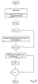
- ein Flußdiagramm zur Ermittlung der Phasenströme für den Elektromotor zwecks Reduktion der elektromagnetischen Drehmomentschwankungen;
- Fig. 3
- eine Darstellung der induzierten Spannung in einer Phase eines vierphasigen Motors in normierter Form;
- Fig. 4
- das Schaltbild einer Einrichtung für die direkte Messung des Stillstandsmomentes eines Mustermotors;
- Fig. 5
- das Schaltbild für eine indirekte Messung des Stillstandsmomentes eines Mustermotors;
- Fig. 6
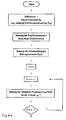
- ein Flußdiagramm zur iterativen Bestimmung der Phasenströme für die Reduktion der permanentmagnetischen und mechanischen Drehmomentschwankungen eines Motors, aufgeteilt in drei Teile (Fig. 6a, 6b und 6c);
- Fig. 7
- eine Darstellung der nach dem Flußdiagramm der Fig. 6 iterativ ermittelten Stromkurve für eine Phase in normierter Form;
- Fig. 8
- eine Darstellung der permanentmagnetischen und mechanischen Drehmomentschwankungen des Prüfmotors im Stillstand vor einer elektronischen Korrektur (ohne Reibungsmoment);
- Fig. 9
- eine Darstellung der Drehmomentschwankungen ähnlich wie in Fig. 8, jedoch nach der elektronischen Korrektur;
- Fig. 10
- das Blockschaltbild in vereinfachter Darstellung einer Anordnung zur Ansteuerung eines elektromechanischen Wandlers in Form eines Elektromotors; und
- Fig. 11a-c
- Darstellungen der Phasenstromkurven des Prüfmotors im stromlosen Zustand, bei einem
Strom von 0,1 A bzw. bei einemStrom von 0,5 A.
- Fig. 1
- the equivalent circuit diagram of a permanent magnet excited synchronous motor;
- Fig. 2
- a flowchart for determining the phase currents for the electric motor for the purpose of reducing the electromagnetic torque fluctuations;
- Fig. 3
- a representation of the induced voltage in a phase of a four-phase motor in a standardized form;
- Fig. 4
- the circuit diagram of a device for the direct measurement of the standstill torque of a sample motor;
- Fig. 5
- the circuit diagram for an indirect measurement of the standstill torque of a sample motor;
- Fig. 6
- a flow diagram for iterative determination of the phase currents for the reduction of the permanent magnetic and mechanical torque fluctuations of a motor, divided into three parts (Fig. 6a, 6b and 6c);
- Fig. 7
- a representation of the current curve determined iteratively according to the flow diagram of FIG. 6 for a phase in standardized form;
- Fig. 8
- a representation of the permanent magnetic and mechanical torque fluctuations of the test motor at a standstill before an electronic correction (without frictional torque);
- Fig. 9
- a representation of the torque fluctuations similar to Figure 8, but after the electronic correction.
- Fig. 10
- the block diagram in a simplified representation of an arrangement for controlling an electromechanical converter in the form of an electric motor; and
- Figures 11a-c
- Representation of the phase current curves of the test motor in the de-energized state, at a current of 0.1 A or at a current of 0.5 A.
Unter dem Begriff "elektromechanischer Wandler" sind beliebige Wandler zu verstehen, die aus einem elektrischen Strom oder einer Spannung eine mechanische Wirkung hervorrufen oder umgekehrt, z.B. elektromagnetische Wandler, piezoelektrische Wandler, Elektretwandler, Thermowandler. Von besonderer Bedeutung sind rotierende Elektromotoren und Generatoren (ideale Bremse) sowie Linearmotoren, aber auch Lautsprecherantriebssysteme, Relais, Stellglieder und Zugmagneten.The term "electromechanical transducer" is understood to mean any transducer which produces a mechanical effect from an electrical current or a voltage or vice versa, e.g. electromagnetic transducers, piezoelectric transducers, electrical transducers, thermal transducers. Of particular importance are rotating electric motors and generators (ideal brake) as well as linear motors, but also loudspeaker drive systems, relays, actuators and pulling magnets.
Da auch das mechanische Verhalten von mit den Wandlern gekuppelten Lasten (z.B. rotierende und allgemeine Hebel- und sonstige Getriebe) den Kraftoder Drehmomentverlauf beeinflussen, können auch diese in Kombination mit den Wandlern berücksichtigt werden.Since the mechanical behavior of loads coupled to the transducers (e.g. rotating and general lever and other gears) also influence the force or torque curve, these can also be taken into account in combination with the transducers.
Auch können sich Kraftschwankungen in anderen Richtungen als die Nutzkraft oder das Nutzmoment auswirken und werden bei Bedarf berücksichtigt. Dies gilt z.B. für axiale oder radiale Störkräfte in rotierenden Wandlern, die sich nicht direkt, sondern indirekt auf das Betriebsverhalten auswirken oder zusätzlichen Verschleiß oder Geräusche verursachen.Force fluctuations in other directions than the useful power or the useful torque can also have an effect and are taken into account if necessary. This applies e.g. For axial or radial interference forces in rotating transducers that do not have a direct but indirect effect on the operating behavior or cause additional wear or noise.
Zunächst sollen anhand des elektrischen Ersatzschaltbildes nach Fig. 1 das Drehmoment bzw. die Drehmomentschwankungen aus der Motorenergiebilanz hergeleitet werden. Die Drehmomentgleichung für das Ersatzschaltbild nach Fig. 1 lautet wie folgt: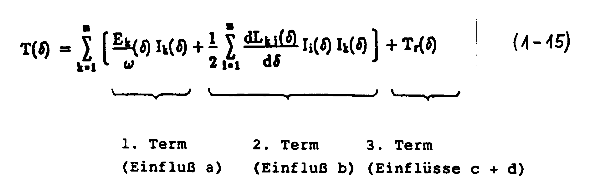
Hierbei sind
- T
- das resultierende Drehmoment
- Tr
- die Summe aus den permanentmagnetischen und den mechanischen Momentenschwankungen,
- E
- die induzierte Phasenspannung,
- I
- der Phasenstrom
- L
- die Motorinduktivität,
- ω
- die Rotorwinkelgeschwindigkeit,
- δ
- der Rotorwinkel,
- m
- Phasenzahl und
- i,k
- Laufvariable für die Motorphasen.
Here are
- T
- the resulting torque
- T r
- the sum of the permanent magnetic and mechanical torque fluctuations,
- E
- the induced phase voltage,
- I.
- the phase current
- L
- the motor inductance,
- ω
- the rotor angular velocity,
- δ
- the rotor angle,
- m
- Phase number and
- i, k
- Run variable for the motor phases.
Wie man aus der Drehmomentgleichung erkennen kann, trägt die Stromänderungsgeschwindigkeit nicht zur Drehmomentbildung bei. Das Gesamtdrehmoment besteht aus vier Anteilen:
- a) der elektromagnetischen Komponente,
- b) der reluktanten Komponente,
- c) der permanentmagnetischen Komponente, und
- d) der mechanischen Komponente.
- a) the electromagnetic component,
- b) the reluctant component,
- c) the permanent magnetic component, and
- d) the mechanical component.
Der erste Term der Drehmomentgleichung beinhaltet den elektromagnetischen Drehmomentanteil. Er wird bestimmt durch die Wechselwirkung zwischen den magnetischen Spulenflüssen und den zugehörigen Ankerströmen. Der elektromagnetische Anteil besteht aus einem konstanten Nutzmoment, sowie einem überlagerten Pulsationsmoment.The first term of the torque equation contains the electromagnetic torque component. It is determined by the interaction between the magnetic coil fluxes and the associated armature currents. The electromagnetic component consists of a constant useful torque and a superimposed pulsation torque.
Der zweite Term aus der Drehmomentgleichung beschreibt das Reluktanzmoment. Eine winkelabhängige Änderung der Motorinduktivität, wie sie beispielsweise bei ungleichförmigem Luftspalt auftritt, führt im Verein mit den Ankerströmen zu einem resultierenden Moment, welches abhängig von der Speisung und Konstruktion aus einem konstanten Nutzmoment und Pulsationsmoment besteht.The second term from the torque equation describes the reluctance torque. A change in the motor inductance as a function of the angle, as occurs, for example, in the case of a non-uniform air gap, leads, in conjunction with the armature currents, to a resulting moment which, depending on the supply and design, consists of a constant useful torque and pulsation torque.
Der dritte Term aus der Drehmomentgleichung zeigt den permanentmagnetischen und den mechanischen Anteil. Dieser erzeugt aufgrund der Wechselwirkung zwischen Ankernuten und Permanentmagneten Rastmomente und somit störende Pulsationen. Die Größe dieser vier Komponenten wird durch das Prinzip und die Motorkonstruktion beeinflußt.The third term from the torque equation shows the permanent magnetic and the mechanical part. Due to the interaction between armature grooves and permanent magnets, this generates cogging moments and thus disturbing pulsations. The size of these four components is influenced by the principle and the engine design.
Isoliert man den elektromagnetischen Drehmomentanteil aus der Drehmomenthauptgleichung (1-15) von den übrigen Komponenten, so ergibt sich:
Zur gewünschten Bedingung
![]()
sollen nun die Beziehungen für die erforderlichen Phasenströme hergeleitet werden.If the electromagnetic torque component from the main torque equation (1-15) is isolated from the other components, the following results:
On the desired condition
![]()
the relationships for the required phase currents are now to be derived.
Das Gleichungssystem (2 -1...2) ist in seiner bisherigen Form unterbestimmt. Eine zweckmäßige Zusatzbedingung kann aufgestellt werden. Hier wurde die Forderung nach minimalen Wicklungsverlusten gewählt:
Zur Lösung dieser Extremwertaufgabe mit m Variablen und der Nebenbedingung (Gleichung 2 -1 und -2) ermittelt man die notwendigen Bedingungen mit Hilfe des Lagrangeschen Multiplikators λ aus folgendem Ansatz:
Dieser Ansatz gilt für eine unabhängige Steuerung der Phasenströme. Eine weitere Zusatzbedingung, zum Beispiel die Forderung
erfordert die Einführung eines weiteren Lagrangeschen Multiplikators. Durch diese Zusatzbedingung kann jedoch die Verlustleistung ansteigen.The system of equations (2 -1 ... 2) is undetermined in its previous form. An appropriate additional condition can be set up. Here the requirement for minimal winding losses was chosen:
To solve this extreme value problem with m variables and the constraint (equations 2 -1 and -2), the necessary conditions are determined using the Lagrangian multiplier λ from the following approach:
This approach applies to independent control of the phase currents. Another additional condition, for example the claim
requires the introduction of another Lagrangian multiplier. However, this additional condition can increase the power loss.
Hieraus gewinnt man
![]()
und
Gleichung (-6) eingesetzt in die Drehmomentgleichung (-1) führt zu
Der Lagrangesche Multiplikator ist somit bestimmt durch
Aus den Beziehungen (-6) und (-8) erhält man die gewünschten Stromgleichungen der Phasen k=1...m zur Reduktion der elektromagnetischen Drehmomentschwankungen:
Diese Phasenströme können in einem rechnergesteuerten Motorprüfstand (der später noch erläutert wird) nach dem Flußdiagramm nach Fig. 2 ermittelt werden. Für das Beispiel eines 2-poligen elektronisch kommutierten Motors mit vier Phasen sind die Stromkurvenformen zur Reduktion der elektromagnetischen Drehmomentschwankung ermittelt worden. Es wurde hierbei ein Motor als Beispiel ausgewählt, der sowohl sehr hohe elektromagnetische als auch permanentmagnetische Drehmomentpulsationen aufweist.You win from this
![]()
and
Equation (-6) inserted in the torque equation (-1) leads to
The Lagrangian multiplier is thus determined by
The desired current equations of the phases k = 1 ... m for reducing the electromagnetic torque fluctuations are obtained from the relationships (-6) and (-8):
These phase currents can be determined in a computer-controlled engine test bench (which will be explained later) according to the flow chart in FIG. 2. For the example of a 2-pole electronically commutated motor with four phases, the current waveforms for reducing the electromagnetic torque fluctuation have been determined. A motor was selected as an example, which has both very high electromagnetic and permanent magnetic torque pulsations.
Die Phasenspannungscharakteristik für eine Phase des Motors ist in Fig. 3 gezeigt. Die induzierten Spannungen wurden bei sehr hoher Drehzahl (5000 U/min) aufgenommen, so daß Störeinflüsse aufgrund von Drehzahlschwankungen vernachlässigbar sind. Falls diese Messungen bei niedrigeren Drehzahlen vorgenommen werden müssen, so wäre eine zusätzliche Schwungmasse erforderlich. Wird dieser Motor mit den nach dem Flußdiagramm nach Fig. 2 bestimmten Phasenstromkurven gespeist, so ergibt sich ein sehr gleichmäßiger Drehmomentverlauf ohne Schwankungen. Eventuelle Reststörungen können durch eine Messung entdekt werden und durch entprechend angepaßte Stromkurven in einem zweiten Schritt oder in zusätzlichen nachfolgenden Schritten eliminiert werden.The phase voltage characteristic for one phase of the motor is shown in FIG. 3. The induced voltages were recorded at a very high speed (5000 rpm), so that disturbances due to speed fluctuations are negligible. If these measurements have to be made at lower speeds, an additional flywheel would be required. If this motor is fed with the phase current curves determined according to the flow diagram according to FIG. 2, the torque curve is very uniform without fluctuations. Any residual disturbances can be detected by a measurement and eliminated by appropriately adapted current curves in a second step or in additional subsequent steps.
Neben dem vorstehend beschriebenen Verfahren zur Berechnung der Motorphasenströme ist es auch möglich, ein Verfahren anzuwenden, das auf der harmonischen Analyse beruht. Zur Kompensation der einzelnen Drehmomentoberschwingungen wird die Ordnungszahl der Stromharmonischen so bestimmt, daß diese mit der größten Spannungsharmonischen (Grundharmonische) zusammenwirken. Die dabei auftretenden Störmomente, die aus der Wechselwirkung der berechneten Stromharmonischen mit Spannungskomponenten entstehen, deren Ordnungszahl von der Grundharmonischen abweicht, werden berechnet und durch einen iterativen Korrekturprozeß schrittweise eliminiert.In addition to the method described above for calculating the motor phase currents, it is also possible to use a method based on the harmonic analysis. To compensate for the individual torque harmonics, the ordinal number of the current harmonics is determined so that they interact with the largest voltage harmonics (basic harmonics). The disturbance torques that arise from the interaction of the calculated current harmonics with voltage components, the atomic number of which Fundamental harmonics deviate, are calculated and eliminated step by step through an iterative correction process.
Ein Vergleich der beiden Berechnungsmethoden zeigt, daß praktisch die gleichen Ergebnisse erzielt werden, wobei die schnellere und in der Lösungsstruktur einfachere Methode das direkte, zuerst beschriebene Verfahren ist.A comparison of the two calculation methods shows that practically the same results are achieved, the faster and simpler method in the solution structure being the direct method described first.
Das permanentmagnetische Rastmoment aus der Drehmomentgleichung (Gl. 1-15) ist eine Funktion des Rotorwinkels δ.
![]()
Im Gegensatz zu den elektromagnetischen Drehmomentpulsationen ist dieser Teil stromunabhängig. Die Bestimmung des Momentenverlaufes kann über eine Feldberechnung oder direkt über eine Messung erfolgen. Der Weg über die (numerischen) Feldberechnungen führt aus den bereits erwähnten Gründen teilweise zu sehr unsicheren Ergebnissen. Hinzu kommt die Unkenntnis der Vorgeschichte der Rotormagnete, die infolge zu hoher thermischer Belastung oder zu großer Ankerrückwirkung bereits partiell teilentmagnetisiert sein können. Die Auswirkung dieser Effekte werden bei einer Drehmomentmessung direkt miterfaßt. Zwei Verfahren bieten sich zur Drehmomentmessung an:


![]()
In contrast to the electromagnetic torque pulsations, this part is independent of the current. The torque curve can be determined via a field calculation or directly via a measurement. For the reasons already mentioned, the route via the (numerical) field calculations sometimes leads to very uncertain results. Added to this is the lack of knowledge of the previous history of the rotor magnets, which may already be partially demagnetized due to excessive thermal stress or excessive armature reaction. The effects of these effects are directly included in a torque measurement. Two methods are available for torque measurement:
Die Funktionsblöcke der beiden Varianten sind in den Figuren 4 und 5 einander gegenübergestellt. Ein Vergleich der vorstehenden Tabelle führt zu dem Resultat, daß je nach Schwerpunkt der Prioritäten beide Verfahren ihre Berechtigung haben.The functional blocks of the two variants are compared with one another in FIGS. 4 and 5. A comparison of the above table leads to the result that depending on the focus of the priorities, both methods are justified.
Für die nachfolgende Beschreibung wird das Verfahren der dynamischen Drehmomentmessung gewählt. Weitere Einzelheiten zu dem Prüfstand sind einer Patentanmeldung mit dem Titel "Meß- und Prüfstand für elektromechanishe Wandler" (gleicher Erfinder, gleicher Anmelder, gleicher Anmeldetag) zu entnehmen.The procedure for dynamic torque measurement is selected for the following description. Further details on the test stand can be found in a patent application entitled "Measuring and test stand for electromechanical transducers" (same inventor, same applicant, same filing date).
Die Herleitung des Gleichungssystems für die Kompensation des permanentmagnetischen und mechanischen Drehmomentanteils beginnt mit der Darstellung der dynamischen Bewegungsgleichung für das Meßsystem nach Fig. 5. Der Antriebsservomotor wird über eine regelbare Spannungsquelle so gesteuert, daß bei möglichst kleiner Drehzahl die permanentmagnetischen Kippmomente des stromlosen Prüfmotors gerade überwunden werden. Das auftretende Moment läßt sich im stationären Zustand über den Ankerstrom des Antriebsmotors messen.
![]()
Für einen DC-Glockenankermotor mit sehr hoher Kollektorlamellenzahl ist der Zusammenhang zwischen Moment und Ankerstrom mit sehr guter Näherung linear. Die Gleichung 3 -2 vereinfacht sich unter der Verwendung der Drehmomentkonstanten kT zu:
![]()
Das meßbare Drehmoment setzt sich aus drei Komponenten zusammen, die im folgenden betrachtet werden.The derivation of the system of equations for the compensation of the permanent magnetic and mechanical torque component begins with the representation of the dynamic equation of motion for the measuring system according to FIG. 5. The drive servo motor is controlled via a controllable voltage source in such a way that the permanent magnetic tilting moments of the currentless test motor are just overcome at the lowest possible speed will. The torque that occurs can be measured in the steady state via the armature current of the drive motor.
![]()
For a DC bell-armature motor with a very high number of collectors, the relationship between torque and armature current is linear with a very good approximation. Equation 3-2 is simplified using the torque constant k T to:
![]()
The measurable torque consists of three components, which are considered below.
Den ersten Term bildet das winkelabhängige Drehmoment:
![]()
Das Rastmoment Tr wird ausgelöst durch eine Überlagerung der permanentmagnetischen Momentschwankungen, der mechanischen Momentschwankungen, sowie des drehzahlunabhängigen Reibungsmomentanteils.The first term is the angle-dependent torque:
![]()
The cogging torque T r is triggered by a superimposition of the permanent magnetic torque fluctuations, the mechanical torque fluctuations and the speed-independent friction torque component.
Der zweite Term wird durch drehzahlabhängige Momentanteile bestimmt:
![]()
Je nach Motorausführung und Betriebsbereich kann die Funktion T2(ω) linear oder auch stark nicht linear von der Drehzahl abhängen. Einflußgrößen sind Lager- und Bürstenreibung, Luftreibung, Wirbelstrom- und Hysteresebremsmomente.The second term is determined by speed-dependent torque components:
![]()
Depending on the motor version and operating range, the function T 2 (ω) can depend linearly or strongly non-linearly on the speed. Influencing variables are bearing and brush friction, air friction, eddy current and hysteresis braking torques.
Der dritte Term schließlich ist das Beschleunigungsmoment, abhängig vom Massenträgheitsmoment des gesamten rotierenden Systems.
mit
- Jp:
- Trägheitsmoment des Prüfmotors,
- Jb:
- Trägheitsmoment der Bremse,
- Jo:
- sonstige Trägheitsmomente (z.B.Kupplung, Winkelgeber).
With
- J p :
- Moment of inertia of the test motor,
- J b :
- Moment of inertia of the brake,
- J o:
- other moments of inertia (e.g. coupling, angle encoder).
Die Drehmomentbilanz aus den Gleichungen ( 3 -2, -4, -5 und -6) lautet somit:
Umgeformt ergibt sich das winkelabhängige Rastmoment zu:
Für die Kompensation der permanetmagnetischen und mechanischen Drehmomentschwankungen ist deshalb folgende Bedingungsgleichung zu erfüllen:
![]()
Die Beziehung für die das elektromagnetische Kompensationsmoment Tc erzeugende Phasenströme läßt sich unter Verwendung von Gleichung ( 2 -9) herleiten. Die exakte Lösung unter der Nebenbedingung minimaler Verluste lautet:
mit Tr (δ) gemäß Gleichung (3 -8).The torque balance from equations (3 -2, -4, -5 and -6) is therefore:
Formed, the angle-dependent cogging torque results in:
For the compensation of the permanent magnetic and mechanical torque fluctuations, the following condition equation must therefore be met:
![]()
The relationship for the phase currents generating the electromagnetic compensation torque T c can be derived using equation (2 -9). The exact solution under the condition of minimal losses is:
with T r (δ) according to equation (3 -8).
Wie bei der Kompensation der elektromagnetischen Drehmomentschwankungen kann auch hier alternativ die Stromkurve auf der Grundlage einer harmonischen Analyse ermittelt werden.As with the compensation of the electromagnetic torque fluctuations, the current curve can alternatively be determined on the basis of a harmonic analysis.
Die Ablauffolge der Berechnung der Phasenstromkurven ist aus dem Flußdiagramm nach Fig. 6 (mit den Teilen Fig. 6a, 6b und 6c) ersichtlich. Die zur Berechnung erforderlichen Messungen am Motor werden auf einem Meß- und Prüfstand vollautomatisch durchgeführt, so daß im Anschluß daran der Motor mit der ermittelten Korrekturkurve betrieben und getestet werden kann.The sequence of the calculation of the phase current curves can be seen from the flow diagram according to FIG. 6 (with the parts of FIGS. 6a, 6b and 6c). The measurements on the engine required for the calculation are carried out fully automatically on a measuring and test stand, so that the engine can then be operated and tested with the determined correction curve.
Fig. 7 zeigt für eine Motorphase die in dem iterativen Verfahren nach dem Flußdiagramm nach Fig. 6 ermittelte Stromkurve in normierter Form zur Kompensation von permanentmagnetischen und mechanischen Drehmomentschwankungen. Die Fig. 8 und 9 zeigen Kurven für das Stillstandsdrehmoment vor bzw. nach der elektronischen Korrektur.FIG. 7 shows, for a motor phase, the current curve determined in the iterative method according to the flow diagram according to FIG. 6 in a standardized form for the compensation of permanent magnetic and mechanical torque fluctuations. 8 and 9 show curves for the standstill torque before and after the electronic correction.
Fig. 10 zeigt nun ein Ausführungsbeispiel in schematischer Darstellung eine Anordnung zur Ansteuerung elektromechanischer Wandler, im vorliegenden Fall eines Elektromotors. Die Schaltungsanordnung nach Fig. 10 enthält einen Motorcontroller 10, eine arithmetische Schaltungseinheit 20, einen Funktionsspeicher 30 sowie eine Leistungsversorgung für den Motor 3, die im vorliegenden Beispiel aus einem Stromregler 5, einer Endstufe 6, einer Gleichspannungsstromversorgung 7 und einer Strommeßvorrichtung 4 besteht. Die arithmetische Schaltungseinheit enthält zwei Multiplizierer 21 und 22 sowie eine Verknüpfungsschaltung in Form eines Akkumulators (Summierers) 23, dessen Ausgangssignal den Stromregler 5 ansteuert. Der Funktionsspeicher 30 enthält im vorliegenden Fall zwei Kurvenspeicher 31 und 32, so daß zwei verschiedene Terme berücksichtigt werden können. Sollten noch weitere Terme, z. B. zur Kompensation von reluktanten oder in andere Richtungen als die Nutzkraft oder das Nutzdrehmoment wirkende Störeinflüsse, verarbeitet werden müssen, so sind die arithmetische Schaltungseinheit 20 und der Funktionsspeicher 30 noch um die entsprechenden Elemente zu erweitern. In einem solchen Fall erfolgen die Verknüpfungen möglicherweise nicht multiplikativ und additiv, wie in Fig. 10 gezeigt, sondern gegebenenfalls durch entsprechende andere funktionelle Verknüpfungen.10 now shows an exemplary embodiment in a schematic representation of an arrangement for actuating electromechanical converters, in the present case an electric motor. 10 contains a
Auch wenn in der Schaltungsanordnung nach Fig. 10 in dem Funktionsspeicher 30 pro Einflußgröße nur je ein Speicherabschnitt 31, 32 gezeigt sind, so kann jeder der Speicherabschnitte in mehrere Teile unter-gliedert sein, damit pro Einflußgröße verschiedene Datensätze gespeichert werden können. Diese verschiedenen Datensätze werden dann durch eine Eingangsgröße 33 ausgewählt.Even if only one
Der Motorcontroller 10 enthält im vorliegenden Fall eine Drehmomentsteuerung 11, einen Drehzahlregler 12 und einen Positionsregler 13, deren Ausgangssignale über einen Umschalter wahlweise an einen Eingang 25 der arithmetischen Schaltungseinheit 20 gelegt werden, sowie eine Drehzahl- und Drehrichtungserkennung 14. Darüber hinaus ist noch ein Eingang 24 für die arithmetische Schaltungseinheit vorgesehen. Der Motor 3 ist mit einem Winkelencoder 2 gekuppelt, um sowohl für den Funktionsspeicher 30 als auch für den Motorcontroller 10 entsprechende Winkelpositionssignale zu liefern.In the present case, the
Stellvertretend für eine Vielzahl von Korrekturoder Steuergliedern (Eingangsgrößen) ist der Eingang 26 oder 27 gezeichnet für eine mögliche Bewertung der Multiplikationsfaktoren 24 bzw. 25. Die Eingangsgröße 33 entscheidet über die Auswahl spezieller Kurven zur Berücksichtigung verschiedener Betriebszustände (nichtlinearer Betrieb aufgrund Eisensättigung und Ankerrückwirkung, Temperatur) und Motorbetriebsarten (z. B. gleichförmiger Betrieb oder pulsierender Betrieb als Schrittmotor).Representing a large number of correction or control elements (input variables),
Folgende Eingangsgrößen sind für die Schaltungsanordnung interessant: Stellgrößen für die Amplituden der gespeicherten nominierten Kurven oder des Kurvengenerators, gegebenenfalls eine Signalgröße, die das Auslesen der Kurven zeitabhängig oder in Abhängigkeit der Rotorstellung ermöglicht, Steuer- oder Signalgrößen zur Auswahl der Kurven und eventuell zur Veränderung der Kurvenform insbesondere bei nichtlinearer Motorcharakteristik, wo entsprechend dem Betriebszustand die Kurvenform anzupassen ist. Weiterhin können beispielsweise noch Steuergrößen für eine arithmetische Schaltungseinheit 20 auftreten, die den Ablauf der Verknüpfung von Stellgrößen und Kurven steuern oder die Verknüpfungsfunktion entsprechend dem Betriebszustand des Motors ändern. Als Ausgangsgrößen entstehen digitale, analoge oder sonstige Signalgrößen, die gegebenenfalls über einen Leistungssteller, definierte Ströme oder Spannungen den Motorphasen einprägen, um die Rundlaufgüte des Motors oder allgemein die Betriebscharakteristik zu verbessern.The following input variables are of interest for the circuit arrangement: manipulated variables for the amplitudes of the stored nominated curves or the curve generator, possibly a signal variable which enables the curves to be read out depending on the time or depending on the rotor position, control or signal variables for selecting the curves and possibly for changing the curves Curve shape especially with non-linear motor characteristics, where the curve shape has to be adjusted according to the operating state. Furthermore, control variables for an
Im Funktionsspeicher 30 sind die Daten für Kurven abgelegt, die zur Kompensation der einzelnen Drehmomentschwankungsarten führen. Die Daten können in Form von Tabellen, Vorschriften (z.B. Begrenzung der maximalen Stromamplitude), Gleichungen oder Funktionen abgespeichert werden. Je nach Symmetrie des magnetischen und elektrischen Kreises ist es nötig, die Kurven für alle Phasen getrennt oder nur je eine Kurve pro Drehmomentschwankungsart abzulegen. Im letzteren Fall werden die Kurven um den Phasenverschiebungswinkel versetzt ausgelesen. An die Stelle der Funktionsspeicher 30 können auch Kurvengeneratoren treten, die die definierten Kurven erzeugen.The data for curves which lead to the compensation of the individual types of torque fluctuations are stored in the
Eine arithmetische Schaltungseinheit 20 verknüpft nun die zeit- oder rotorwinkelabhängig zur Verfügung gestellten Kurvenamplituden mit den Eingangsstellgrößen nach definierten Funktionen. Im vorliegenden Fall sind die Verknüpfungsglieder 21, 22 bzw. Addierglieder 23; für die Berücksichtigung anderer Einflußgrößen sind jedoch u. U. andere Verknüpfungen notwendig.An
In der Schaltungsanordnung nach Fig. 10 werden die für eine Rotorumdrehung berechneten Stromkurvenwerte der einzelnen Phasen zur Reduktion der elektromagnetischen Drehmomentschwankung (Kurvenspeicher 32) und der Permanentmagnetischen einschließlich der mechanischen Schwankung (Kurvenspeicher 31) getrennt und in normierter Form abgelegt.In the circuit arrangement according to FIG. 10, the current curve values calculated for a rotor revolution of the individual phases for reducing the electromagnetic torque fluctuation (curve memory 32) and the permanent magnetic including the mechanical fluctuation (curve memory 31) are separated and stored in standardized form.
Entsprechend dem Rotorwinkel φ wird die Stromkurve des Kurvenspeichers 31 ausgelesen und mit einer Stromamplitude iA (Eingang 24) multipliziert. Die Amplitude iA ist so gewählt, daß die permanentmagnetischen Drehmomentschwankungen minimal werden. Auch die Amplitude iA ist im abgespeicherten Datesatz enthalten. Bei Motoren mit ungesättigtem Eisenkreis und vernachlässigbarer Ankerrückwirkung kann die Amplitude konstant gehalten werden. Anderenfalls ist der Wert entsprechend den Gegebenheiten nachzuführen. Die auf diese Weise erzeugte Stromkurve fließt unverändert in die einzelnen Phasenwicklungen, unabhängig vom Betriebszustand des Motors und kompensiert somit die permanentmagnetisch und mechanisch verursachten Drehmomentpulsationen.The current curve of the
Unter der Voraussetzung, daß der Motor eine lineare Strom-Drehmomentcharakteristik besitzt, was bei permanentmagneterregten Motoren in der Regel gegeben ist, kann nun der Stromkurve
![]()
die eigentliche Betriebskurve additiv überlagert werden. Sie entsteht durch das Produkt aus der Regler-Stromamplitude mit der für die Kompensation der elektromagnetischen Drehmomentschwankungen bestimmten Stromkurve B(φ):
![]()
Zeigt der betreffende Motor ein nichtlineares Verhalten, so ist es zweckmäßig, verschiedene Kurven pro Drehmomentschwankungsart für verschiedene Betriebsbereiche einzusetzen. Dies kann beispielsweise dadurch erfolgen, daß man abhängig vom Betriebszustand des Motors einen Kurvenauswahlschalter realisiert, der über einen Eingang 33 die entsprechenden Abschnitte der Speicherabschnitte 31, 32 usw. auswählt. Oder die Kurven werden geeignet verändert, so daß sie besser an den jeweiligen Betriebszustand angepaßt sind. Eine Anpassung kann aber auch über eine Veränderung der Eingangsstellgrößen 26, 27 erfolgen.Provided that the motor has a linear current-torque characteristic, which at given permanent magnet motors, the current curve can now
![]()
the actual operating curve are additively superimposed. It results from the product of the controller current amplitude with the current curve B (φ) intended for the compensation of the electromagnetic torque fluctuations:
![]()
If the motor in question shows non-linear behavior, it is advisable to use different curves for each type of torque fluctuation for different operating ranges. This can be done, for example, by implementing a curve selection switch depending on the operating state of the engine, which selects the corresponding sections of the
Für den Fall, daß die reluktanten Drehmomentschwankungen oder noch andere Einflüsse nicht vernachlässigbar sind, kann der Schaltung nach Fig. 10 noch ein dritter Pfad oder noch weitere Pfade, bestehend aus einem zusätzlichen Speicherabschnitt und einem Verknüpfungsglied (nicht gezeigt), hinzugefügt werden, der die Reduktion der reluktanten Schwankungen durch entsprechende Stromverläufe erlaubt.In the event that the reluctant torque fluctuations or other influences are not negligible, a third path or further paths, consisting of an additional memory section and a logic element (not shown), can be added to the circuit according to FIG. 10, which the Reduction of the reluctant fluctuations allowed by appropriate current profiles.
Aus der eingangs angeführten Drehmomentengleichung geht hervor, daß dieser Term von den Selbst- und Gegeninduktivitäten sowie von den einzelnen Phasenströmen abhängig sein kann. Es ist möglich, die nötige Information für die Stromkurvengenerierung als Datensätze in Form von Tabellenwerten, Vorschriften, Gleichungen oder Funktionen abzulegen, oder die Information direkt aus dem jeweiligen Betriebszustand zu errechnen.It can be seen from the torque equation mentioned at the beginning that this term can depend on the self-inductance and mutual inductance as well as on the individual phase currents. It is possible to store the necessary information for the generation of the current curve as data records in the form of table values, regulations, equations or functions, or to calculate the information directly from the respective operating state.
Die Realisation der elektrischen Schaltung kann auf verschiedene Weisen erfolgen. Sie kann beispielsweise rein hardwaremäßig aus analogen und/oder digitalen Bausteinen aufgebaut sein, oder sie kann auch softwaremäßig durch ein Rechnerprogramm realisiert werden. Der elektrischen Schaltung kann nun zusätzlich eine Momentensteuerung, sowie eine Positions-, Drehzahl- oder Beschleunigungsregelung überlagert werden. Im gezeigten Fall hat die Gesamtschaltung die Struktur einer Kaskadenregelung. Dem Positionsregler 13 ist im Motorcontroller 10 intern ein Drehzahlregler 12 und diesem extern ein Stromregler 5 unterlagert.The electrical circuit can be implemented in various ways. For example, it can be constructed purely in terms of hardware from analog and / or digital modules, or it can also be implemented in software using a computer program. A torque control as well as a position, speed or acceleration control can now be superimposed on the electrical circuit. In the case shown, the overall circuit has the structure of a cascade control. A
Der wesentliche Unterschied zu anderen Positions-, Drehzahl-, Beschleunigungs- und Momentenregelungen liegt darin begründet, daß aufgrund der gewählten Stromkurvensteuerung eventuelle Momentenschwankungen bereits im Ansatz unterdrückt und somit die überlagerten Regelkreise sehr stark entlastet werden. Die Regler sind lediglich noch für eine Feinkorrektur auszulegen. Für die Einprägung eines Drehmomentes kann ein Regler ganz entfallen.The main difference to other position, speed, acceleration and torque controls lies in the fact that due to the selected current curve control any torque fluctuations are suppressed even in the beginning and thus the superimposed control loops are relieved very much. The controllers are only to be designed for a fine correction. There is no need for a controller to impress a torque.
Durch diese vorgestellten Maßnahmen wird das Betriebsverhalten des Motors bezüglich Momenten- und somit auch Drehzahlschwankungen wesentlich verbessert. Weitere Verbesserungen sind geringere Geräuschentwicklung, bessserer Wirkungsgrad und geringere Betriebstemperaturen.Through these measures presented, the operating behavior of the engine with respect to torque and thus speed fluctuations is significantly improved. Other improvements include lower noise, better efficiency and lower operating temperatures.
Die vorgeschlagene elektronische Schaltung eignet sich zur Ansteuerung von Motoren mit beliebigen Stromkurven. Fügt man parallel zum Winkelencoder 2 einen zusätzlichen in der Frequenz steuerbaren Pulsgenerator hinzu, so eignet sich diese Schaltung für den universellen Betrieb von allen elektrischen Kleinmotorenarten, also auch für fremdgesteuerte und nicht positionsgesteuerte Motoren, wie allgemeine Synchronmotoren, Schrittmotoren, Asynchronmotoren etc. Für den rückgekoppelten Betrieb schaltet man den Winkelencoder 2 und für den gesteuerten Betrieb den Pulsgenerator in den elektrischen Kreis.The proposed electronic circuit is suitable for controlling motors with any current curve. If you add an additional frequency-controllable pulse generator parallel to the
Die Fig. 11a, 11b und 11c zeigen nun für eine Phase Stromkurven zur Erzielung verschiedener Konstant-Nenndrehmomente, wie sie z.B. mittels der Schaltungsanordnung nach Fig. 10 an den Motor 3 gelegt werden. Diese Kurven berücksichtigen beide Anteile von Drehmomentschwankungen, nämlich die elektromagnetischen und die permanentmagnetischen Schwankungen. Es werden Phasenstromkurven für drei verschiedene Betriebszustände des Motors 3 gezeigt, und zwar für den stromlosen Zustand (Fig. 11a) für einen Stom von 0,1 A (Fig. 11b) und für einen Strom von 0,5 A (Fig. 11c). Es ergibt sich dabei ein sehr gleichmäßiger Drehmomentverlauf ohne Schwankungen.11a, 11b and 11c now show current curves for one phase in order to achieve different constant nominal torques, such as are applied to the
-
1. Hanitsch, R., Lindner, J.
Scheibenläufermotoren mit Seltenerdmagneten,Techn.Rundschau, 14. Juni 19831. Hanitsch, R., Lindner, J.
Disc rotor motors with rare earth magnets, Technical Review, June 14, 1983 -
2. N.N.
General Purpose Motion Control IC: HCTL 1000, Druckschrift der Firma Hewlett Packard, Nov. 19852. NN
General Purpose Motion Control IC: HCTL 1000, printed by Hewlett Packard, Nov. 1985 -
3. Braun, W.
Die harmonische Steuerung von selbstgeführten Wechselrichtern zur Speisung von Käfigläufermotoren mit Unterdrückung der massgebenden Stromoberschwingungen, Diss. Universität Stuttgart, 19723. Braun, W.
The harmonic control of self-commutated inverters for feeding squirrel-cage motors with suppression of the relevant current harmonics, Diss. Universität Stuttgart, 1972 -
4. Le-Huy, Perret, Feuillet
Minimization of Torque Ripple in Brushless DC-Motor Drives, Industry Applications, IEEE, 28/19854. Le-Huy, Perret, Feuillet
Minimization of Torque Ripple in Brushless DC-Motor Drives, Industry Applications, IEEE, 28/1985 -
5. Bolton, H., Ashen, R.
Influence of Motor Design and Feed-Current Waveform on Torque Ripple in Brushless DC-Drives, IEE Proceedings, Vol. 131, No. 3, May 19845. Bolton, H., Ashen, R.
Influence of Motor Design and Feed-Current Waveform on Torque Ripple in Brushless DC-Drives, IEE Proceedings, Vol. 131, No. 3, May 1984 -
6. Grotstollen, H.
Die Unterdrueckung der Oberwellendrehmomente von Synchronmotoren durch Speisung mit oberschwingungsbehaftetem Strom, Archiv fuer Elektrotechnik, 67 (1984)6. Grotstollen, H.
Suppression of harmonic torques in synchronous motors by supplying them with harmonic current, Archiv für Elektrotechnik, 67 (1984) -
7. Weschta, A.
Pendelmomente von permanentmagneterregten Synchron-Servomotoren, etz Archiv, Bd. 5(1983) H. 47. Weschta, A.
Pendulum moments of permanent magnet excited synchronous servomotors, etz Archiv, Vol. 5 (1983) H. 4 -
8. Schröder, M.
Einfach anzuwendendes Verfahren zur Unterdrückung der Pendelmomente dauermagneterregter Synchronmaschinen, etz Archiv, Bd. 10 (1988) H. 18. Schröder, M.
Easy-to-use method for suppressing the pendulum moments of permanent magnet excited synchronous machines, etz Archiv, Vol. 10 (1988) H. 1 -
9. Schröder, M.
Hochtouriger bürstenloser Positionierantrieb mit extrem geringer Momenten-welligkeit, Diss., Universität Stuttgart, 19869. Schröder, M.
High-speed brushless positioning drive with extremely low torque ripple, diss., University of Stuttgart, 1986
Claims (19)
- A process for controlling electromagnetic transformers for the purpose of producing a predetermined power and moment of rotation characteristic, in particular for the reduction of angle-dependent moment of rotation fluctuations in electric motors,
in which in a function memory (30) are stored time-dependent or position-dependent (dependent on the path and angle of rotation) data sets, which are fetched in dependence on the path and angle of rotation covered in operation or in a time-controlled manner and in an arithmetic switching unit (20) are connected to an input variable to provide instantaneous values,
in which in dependence on the instantaneous values voltages or currents having a corresponding time-dependent or position-dependent curve shape are inputted into the electrical connections of the transformer (3),
characterised in that in the function memory (30) are stored several different data sets taking into consideration different influences determined from the power and moment of rotation characteristic of the transformer (3) and if necessary of a connected load, in particular in the form of tables, rules, equations or functions,
in that these data sets are fetched from the function memory (30) in dependence on position or time and are separately connected according to the influences in sets to at least one input variable (24, 25, 26, 27),
and in that these connecting results obtained in this manner are collated to form the position- and time-dependent instantaneous values. - A process according to Claim 1 for controlling electromagnetic transformers (3),
characterised in that at least two of the subsequent variables influencing the power and moment of rotation characteristic of the transformer (3) and if necessary the connected load are taken into consideration:a) electromagnetic influences,b) reluctance influences,c) permanent magnetic influences,d) mechanical influences (in the transformer and if necessary also the connected load). - A process for controlling electromagnetic transformers for the purpose of producing a predetermined force and moment of rotation characteristic, in particular for the reduction of angle-dependent moment of rotation fluctuations in electric motors,
in which in a function memory (30) are stored position-dependent (dependent on the path and angle of rotation) data sets, which are fetched in dependence on the path and angle of rotation in operation or in a time-controlled manner and in an arithmetic switching unit (20) are connected to an input variable to provide instantaneous values, and
in which in dependence on the instantaneous values voltages or currents having corresponding time- or position-dependent curve shape are inputted into the electrical connections of the transformer (3),
characterised in that in the function memory (30) is stored a data set, which is determined from the power and moment of rotation characteristic of the transformer (3) and takes into consideration the permanent magnetic effects of the transformer,
in that this data set is fetched from the function memory (30) in a position-dependent or time-dependent manner and is connected to at least one input variable (24, 25, 26, 27),
and in that the connection results obtained in this manner represent the position-dependent and time-dependent instantaneous values. - A process for controlling electromechanical transformers (3) for the purpose of producing a predetermined force and moment of rotation characteristic, in particular for the reduction of angle-dependent moment of rotation fluctuations in electric motors,
in which in a function memory (30) are stored position-dependent (dependent on the path and the angle of rotation) data sets, which are fetched in dependence on the path and angle of rotation covered in operation or in a time-controlled manner and in an arithmetical switching unit (20) are connected to an input variable to provide instantaneous values, and
in which in dependence on the instantaneous values voltages or currents having corresponding time- or position-dependent curve shape are inputted into the electrical connections of the transformer (3),
characterised in that in the function memory a data set, which is determined from the force and moment of rotation characteristic of the transformer and if necessary the connected load, and which takes into consideration the mechanical influences, is fetched in dependence on position on time from the function memory and is connected to at least one input variable (24, 25, 26),
and in that these connection results obtained in this manner represent the position- and time-dependent instantaneous values. - A process according to one of Claims 1 to 4,
characterised in that not only an input of current or voltage components for the desired useful power or for the useful moment occurs, but in addition an input of current or voltage components occurs for the compensation of disturbance powers or moments, the directions of which differ from the direction of the useful power and useful moment respectively. - A process according to Claim 5 for an electric motor (3),
characterised in that the input of these voltages or currents taking into consideration the disturbance powers or moments in other directions is performed at least partly via auxiliary windings. - A process according to one of Claims 1 to 6,
characterised in that the data sets taking into consideration the power and moment of rotation characteristic of the transformer (3) and if necessary of the load are only calculated from the given constructional and material data. - A process according to one of Claims 1 to 6,
characterised in that the data sets taking into consideration the power and moment of rotation characteristic of the transformer (3) and if necessary of the load are calculated from parameters and/or characteristic curves measured on a model. - A process according to one of Claims 1 to 6,
characterised in that the data sets taking into consideration the power and moment of rotation characteristic of the transformer (3) and if necessary the load are determined by test runs for optimisation for the purpose of achieving the predetermined power and moment of rotation characteristic of a model on a measuring and test stand. - A process according to Claim 7, 8 or 9 in conjunction with Claim 2 or 4,
characterised in that in addition to the influences of the transformer (3) the influences of a load coupled with the transformer are further taken into consideration. - A process according to one or more of Claims 1 to 10,
characterised in that at least one of the input variables (24, 25, 26, 27) is a constant or in operating states such as non-linear transformer characteristic, iron saturation, armature reaction, etc is a variable adapted to these effects. - A process according to one or more of Claims 1 to 10,
characterised in that at least one of the input variables (24, 25, 26, 27) is a command variable, e.g. for a power, moment, moment of rotation, acceleration and/or position regulation or control. - A process according to Claim 11 or 12,
characterised in that the input variables (24, 25, 26, 27) can be switched over. - A process according to one or more of the preceding Claims,
characterised in that several data sets are provided per influence, which can be selected by a further input variable (26, 27) in dependence on the operating state, in particular to take into consideration non-linear transformer characteristics, iron saturation, armature reaction, etc, and/or to change the operational behaviour of the transformer (3). - An arrangement for performing the process according to one or more of the preceding Claims,
characterised by a function memory (30) having one memory section (31, 32) per influence to be taken into consideration for the storage of the associated data set,
an arithmetical switching unit (20) for connecting data sets read out of the memory sections with at least one input variable (24, 25, 26) and for collating the connection results to provide instantaneous values,
a position or timing unit (2) associated with the electromechanical transformer (3) for controlling the position-dependent and time-dependent reading-out operation of the data in the function memory, and
an output stage (6) for inputting voltages or currents into the electrical connections of the transformer (3) corresponding to the instantaneous values. - An arrangement according to Claim 15,
characterised in that the arithmetical switching unit (20) contains multiplication elements (21, 22) for connecting the read-out data sets with at least one input variable (24, 25, 26, 27) and also addition/subtraction elements (23) for the nonevaluated or evaluated collation of the multiplication results. - An arrangement according to Claim 15 or 16 for a multi-phase transformer (3),
characterised in that for each of the individual phases are stored corresponding data sets and in conjunction with the input variables (24, 25, 26, 27) corresponding instantaneous values are derived,
and in that for each of the individual phases corresponding function memories (30), arithmetic switching units (20) and power output stages (6) are provided or they are operated in the time multiplex. - An arrangement according to Claim 15 or 16 for a multi-phase transformer (3),
characterised in that data sets common to all phases are stored,
and in that for the individual phases these data sets are read out with phase shifting and are connected by the arithmetical switching units (20) in conjunction with the input variables (24, 25, 26, 27) to provide instantaneous values for the individual phases. - An arrangement according to Claim 15 or 16 for a multiphase transformer (3),
characterised in that data sets common to all phases are stored and from them are derived common instantaneous values,
and in that a phase shift unit is provided, which from the common instantaneous values derives the instantaneous values for all phases shifted by the corresponding phase angle.
Applications Claiming Priority (11)
| Application Number | Priority Date | Filing Date | Title |
|---|---|---|---|
| CH4643/88 | 1988-12-15 | ||
| CH464488 | 1988-12-15 | ||
| CH464388 | 1988-12-15 | ||
| CH4644/88 | 1988-12-18 | ||
| CH76389 | 1989-03-02 | ||
| CH763/89 | 1989-03-02 | ||
| CH1523/89 | 1989-04-21 | ||
| CH152389 | 1989-04-21 | ||
| DE3930898 | 1989-09-15 | ||
| DE3930898 | 1989-09-15 | ||
| PCT/EP1989/001545 WO1990007229A1 (en) | 1988-12-15 | 1989-12-15 | Process and installation for the control of electro-mechanical converters |
Publications (2)
| Publication Number | Publication Date |
|---|---|
| EP0448610A1 EP0448610A1 (en) | 1991-10-02 |
| EP0448610B1 true EP0448610B1 (en) | 1994-06-29 |
Family
ID=27508887
Family Applications (2)
| Application Number | Title | Priority Date | Filing Date |
|---|---|---|---|
| EP90900794A Expired - Lifetime EP0448610B1 (en) | 1988-12-15 | 1989-12-15 | Process and installation for the control of electro-mechanical converters |
| EP89123200A Withdrawn EP0377854A1 (en) | 1988-12-15 | 1989-12-15 | Test and measurement stand for an electromechanical converter |
Family Applications After (1)
| Application Number | Title | Priority Date | Filing Date |
|---|---|---|---|
| EP89123200A Withdrawn EP0377854A1 (en) | 1988-12-15 | 1989-12-15 | Test and measurement stand for an electromechanical converter |
Country Status (4)
| Country | Link |
|---|---|
| US (1) | US5274313A (en) |
| EP (2) | EP0448610B1 (en) |
| DE (1) | DE58907988D1 (en) |
| WO (1) | WO1990007229A1 (en) |
Families Citing this family (17)
| Publication number | Priority date | Publication date | Assignee | Title |
|---|---|---|---|---|
| US5638051A (en) * | 1991-10-25 | 1997-06-10 | Siemens Aktiengesellschaft | Method and apparatus for monitoring an electrical drive |
| JP3066622B2 (en) * | 1992-08-04 | 2000-07-17 | 本田技研工業株式会社 | Synchronous motor controller for electric vehicles |
| DE69226532D1 (en) * | 1992-12-30 | 1998-09-10 | Ansaldo Energia Spa | Rotor short circuit detector |
| US5485071A (en) * | 1993-08-09 | 1996-01-16 | Bi; Chao | Method and apparatus for establishing a reference current for use in operating a synchronous motor |
| JPH07170777A (en) * | 1993-12-14 | 1995-07-04 | Fuji Electric Co Ltd | Vibration suppressing controller for motor |
| US5886493A (en) * | 1995-02-16 | 1999-03-23 | The Kansai Electric Power Co., Inc. | Synchronous machine excitation control device for absorbing harmonics superposed onto fundamental current |
| US5621294A (en) * | 1995-11-21 | 1997-04-15 | Universal Instruments Corporation | Apparatus and method for force compensation in a variable reluctance motor |
| JP3806985B2 (en) * | 1996-08-21 | 2006-08-09 | 株式会社ニコン | Stepping motor drive device |
| US5886489A (en) * | 1996-12-04 | 1999-03-23 | International Business Machines Corporation | Apparatus and method for reducing spindle power and acoustic noise in a disk drive |
| FI112891B (en) * | 1998-09-04 | 2004-01-30 | Kone Corp | Method for Controlling a Powered Motor |
| GB0109643D0 (en) * | 2001-04-19 | 2001-06-13 | Isis Innovation | System and method for monitoring and control |
| US6480130B1 (en) * | 2001-06-28 | 2002-11-12 | Honeywell International Inc. | Method for improving repeatability and removing hysteresis from electromechanical actuators |
| US7117754B2 (en) * | 2002-10-28 | 2006-10-10 | The Curators Of The University Of Missouri | Torque ripple sensor and mitigation mechanism |
| WO2004082482A1 (en) * | 2003-03-20 | 2004-09-30 | Matsushita Electric Industrial Co. Ltd. | Ultrasonic probe and ultrasonographic device |
| JP2005033959A (en) * | 2003-07-10 | 2005-02-03 | Fanuc Ltd | Motor and its control |
| DE102004001932B4 (en) * | 2004-01-14 | 2009-10-01 | Minebea Co., Ltd. | Method for controlling an electronically commutated motor and motor control |
| EP2706420B1 (en) * | 2012-09-05 | 2015-03-18 | Siemens Aktiengesellschaft | Method for operating an automation device |
Family Cites Families (22)
| Publication number | Priority date | Publication date | Assignee | Title |
|---|---|---|---|---|
| DE1954089A1 (en) * | 1969-10-28 | 1971-05-06 | Siemens Ag | Device for generating a quantity proportional to the torque of an induction machine |
| US3839665A (en) * | 1970-03-30 | 1974-10-01 | A Gabor | Apparatus measuring relative velocity of movable members including means to detect velocity from the position encoder |
| DE2420166A1 (en) * | 1974-04-25 | 1975-11-13 | Siemens Ag | Electrical machine angular displacement sensor - has two probes using Hall generators or inductive coils with differential amplifiers and pulse former |
| DE2737372C3 (en) * | 1977-08-18 | 1980-08-14 | Max-Planck-Gesellschaft Zur Foerderung Der Wissenschaften E.V., 3400 Goettingen | Device for generating a periodic reciprocating rectilinear movement of a component at a substantially constant speed |
| US4228396A (en) * | 1978-05-26 | 1980-10-14 | Dataproducts Corporation | Electronic tachometer and combined brushless motor commutation and tachometer system |
| DE2834740A1 (en) * | 1978-08-08 | 1980-02-21 | Franz Vertriebs Gmbh | Drive for record player - has motor rotating with tachogenerator carrying microcomputer, which scans stored sine-cosine function |
| US4205383A (en) * | 1978-11-13 | 1980-05-27 | Bakanovich Eduard A | Method of testing objects for random actions thereon and digital simulator-computer system for effecting same |
| IT1165014B (en) * | 1979-03-27 | 1987-04-22 | Innocenti Santeustacchio Spa | GEOMETRIC CONTROL SYSTEM, TO INCREASE THE ACCURACY OF A MACHINE TOOL, PARTICULARLY OF A LARGE DIMENSION MACHINE TOOL |
| US4270074A (en) * | 1979-10-22 | 1981-05-26 | The Singer Company | Brushless DC motor control utilizing a ROM |
| US4429262A (en) * | 1980-09-12 | 1984-01-31 | Technicare Corporation | Three phase motor oscillatory servo control |
| US4447771A (en) * | 1981-08-31 | 1984-05-08 | Kollmorgen Technologies Corporation | Control system for synchronous brushless motors |
| US4559485A (en) * | 1981-08-31 | 1985-12-17 | Kollmorgen Technologies Corporation | Control systems for AC induction motors |
| JPS59123482A (en) * | 1982-12-29 | 1984-07-17 | Fanuc Ltd | Control system for synchronous motor |
| EP0180083B1 (en) * | 1984-10-19 | 1990-08-22 | Kollmorgen Corporation | Control systems for variable reluctance electrical machines |
| JPH0667258B2 (en) * | 1985-08-12 | 1994-08-24 | 松下電器産業株式会社 | Brushless motor |
| JPS63314195A (en) * | 1987-01-30 | 1988-12-22 | Nippon Digital Equip Kenkyu Kaihatsu Center Kk | Method and device for driving 3-phase dc brushless motor |
| US4841184A (en) * | 1987-06-23 | 1989-06-20 | Mechanical Technology Incorporated | Velocity and imbalance observer control circuit for active magnetic bearing or damper |
| US4814677A (en) * | 1987-12-14 | 1989-03-21 | General Electric Company | Field orientation control of a permanent magnet motor |
| US4884016A (en) * | 1988-08-23 | 1989-11-28 | Aerotech, Inc. | Closed loop torque angle control of synchronous motor |
| JPH0295192A (en) * | 1988-09-29 | 1990-04-05 | Sony Corp | Rotation control circuit for hall motor |
| US5023528A (en) * | 1988-10-27 | 1991-06-11 | Advanced Engineering Systems, Operation & Products, Inc. | Method of three-phase winding motor control of rotary motor-driven linear actuators, linear motor-actuated carriages, and similar systems, and apparatus for practicing the same |
| US4999534A (en) * | 1990-01-19 | 1991-03-12 | Contraves Goerz Corporation | Active vibration reduction in apparatus with cross-coupling between control axes |
-
1989
- 1989-12-15 EP EP90900794A patent/EP0448610B1/en not_active Expired - Lifetime
- 1989-12-15 WO PCT/EP1989/001545 patent/WO1990007229A1/en active IP Right Grant
- 1989-12-15 EP EP89123200A patent/EP0377854A1/en not_active Withdrawn
- 1989-12-15 DE DE58907988T patent/DE58907988D1/en not_active Expired - Fee Related
- 1989-12-15 US US07/681,511 patent/US5274313A/en not_active Expired - Fee Related
Also Published As
| Publication number | Publication date |
|---|---|
| WO1990007229A1 (en) | 1990-06-28 |
| US5274313A (en) | 1993-12-28 |
| EP0377854A1 (en) | 1990-07-18 |
| EP0448610A1 (en) | 1991-10-02 |
| DE58907988D1 (en) | 1994-08-04 |
Similar Documents
| Publication | Publication Date | Title |
|---|---|---|
| EP0448610B1 (en) | Process and installation for the control of electro-mechanical converters | |
| EP0151296B1 (en) | Control circuit for a stepper motor | |
| DE3941553A1 (en) | METHOD AND ARRANGEMENT FOR CONTROLLING ELECTROMECHANICAL CONVERTERS | |
| DE69731578T2 (en) | Brushless motor control device and device for detecting the armature position of such a motor | |
| DE60029548T2 (en) | Regulation for a brushless machine | |
| DE2341761C3 (en) | Circuit arrangement for operating a track-bound traction vehicle with a synchronous linear motor | |
| DE4437793C2 (en) | Method and device for controlling an electric motor | |
| DE69930114T2 (en) | MOTOR CONTROL DEVICE | |
| DE69818585T2 (en) | Method for regulating torque fluctuations of a motor with permanent magnets inside and a controller using this method | |
| DE112009001282B4 (en) | Turning angle detector | |
| DE3504681C2 (en) | ||
| EP3134964B1 (en) | Method and device for torque ripple reduction of a dc motor | |
| EP0762625A1 (en) | Electric drive | |
| DE2758423A1 (en) | ELECTRIC DRIVE | |
| DE2803839C2 (en) | ||
| WO2020064420A1 (en) | Reducing interference noises and/or vibrations during the operation of an electric machine | |
| DE2612721B2 (en) | Circuit arrangement for regulating the speed and the angular position of the rotor of a DC motor | |
| EP0690556B1 (en) | Stop recognizing of inverter controlled motor without speed sensor by restarting | |
| DE60036679T2 (en) | Control for a switched reluctance machine | |
| DE3740712A1 (en) | ACCELERATION CONTROL DEVICE | |
| DE19503492A1 (en) | Adjustment and control system drive and position measurement device | |
| DE2914495A1 (en) | CIRCULAR SHORE DRIVE | |
| EP0469177A1 (en) | Method and device for restarting an induction motor | |
| DE60038648T2 (en) | Control process for a rotating machine and device for supplying this machine | |
| EP1127278B1 (en) | Device and method for generating a partially synthesized signal with very good dynamic quality for the acceleration of a rotor in an electrical drive mechanism |
Legal Events
| Date | Code | Title | Description |
|---|---|---|---|
| PUAI | Public reference made under article 153(3) epc to a published international application that has entered the european phase |
Free format text: ORIGINAL CODE: 0009012 |
|
| 17P | Request for examination filed |
Effective date: 19910601 |
|
| AK | Designated contracting states |
Kind code of ref document: A1 Designated state(s): CH DE FR GB IT LI NL SE |
|
| 17Q | First examination report despatched |
Effective date: 19920615 |
|
| RBV | Designated contracting states (corrected) |
Designated state(s): DE GB IT |
|
| GRAA | (expected) grant |
Free format text: ORIGINAL CODE: 0009210 |
|
| AK | Designated contracting states |
Kind code of ref document: B1 Designated state(s): DE GB IT |
|
| ITF | It: translation for a ep patent filed |
Owner name: FIAMMENGHI FIAMMENGHI RACHELI |
|
| REF | Corresponds to: |
Ref document number: 58907988 Country of ref document: DE Date of ref document: 19940804 |
|
| GBT | Gb: translation of ep patent filed (gb section 77(6)(a)/1977) |
Effective date: 19940802 |
|
| RAP2 | Party data changed (patent owner data changed or rights of a patent transferred) |
Owner name: PAPST LICENSING GMBH |
|
| ITTA | It: last paid annual fee | ||
| REG | Reference to a national code |
Ref country code: GB Ref legal event code: 732E |
|
| PLBE | No opposition filed within time limit |
Free format text: ORIGINAL CODE: 0009261 |
|
| STAA | Information on the status of an ep patent application or granted ep patent |
Free format text: STATUS: NO OPPOSITION FILED WITHIN TIME LIMIT |
|
| 26N | No opposition filed | ||
| REG | Reference to a national code |
Ref country code: GB Ref legal event code: IF02 |
|
| PGFP | Annual fee paid to national office [announced via postgrant information from national office to epo] |
Ref country code: GB Payment date: 20041203 Year of fee payment: 16 |
|
| PGFP | Annual fee paid to national office [announced via postgrant information from national office to epo] |
Ref country code: DE Payment date: 20050125 Year of fee payment: 16 |
|
| PG25 | Lapsed in a contracting state [announced via postgrant information from national office to epo] |
Ref country code: IT Free format text: LAPSE BECAUSE OF NON-PAYMENT OF DUE FEES;WARNING: LAPSES OF ITALIAN PATENTS WITH EFFECTIVE DATE BEFORE 2007 MAY HAVE OCCURRED AT ANY TIME BEFORE 2007. THE CORRECT EFFECTIVE DATE MAY BE DIFFERENT FROM THE ONE RECORDED. Effective date: 20051215 Ref country code: GB Free format text: LAPSE BECAUSE OF NON-PAYMENT OF DUE FEES Effective date: 20051215 |
|
| PG25 | Lapsed in a contracting state [announced via postgrant information from national office to epo] |
Ref country code: DE Free format text: LAPSE BECAUSE OF NON-PAYMENT OF DUE FEES Effective date: 20060701 |
|
| GBPC | Gb: european patent ceased through non-payment of renewal fee |
Effective date: 20051215 |