EP0448385B1 - Sheet handling apparatus - Google Patents
Sheet handling apparatus Download PDFInfo
- Publication number
- EP0448385B1 EP0448385B1 EP91302444A EP91302444A EP0448385B1 EP 0448385 B1 EP0448385 B1 EP 0448385B1 EP 91302444 A EP91302444 A EP 91302444A EP 91302444 A EP91302444 A EP 91302444A EP 0448385 B1 EP0448385 B1 EP 0448385B1
- Authority
- EP
- European Patent Office
- Prior art keywords
- pick
- sheet
- suction
- note
- electronic control
- Prior art date
- Legal status (The legal status is an assumption and is not a legal conclusion. Google has not performed a legal analysis and makes no representation as to the accuracy of the status listed.)
- Expired - Lifetime
Links
Images


Classifications
-
- B—PERFORMING OPERATIONS; TRANSPORTING
- B65—CONVEYING; PACKING; STORING; HANDLING THIN OR FILAMENTARY MATERIAL
- B65H—HANDLING THIN OR FILAMENTARY MATERIAL, e.g. SHEETS, WEBS, CABLES
- B65H3/00—Separating articles from piles
- B65H3/08—Separating articles from piles using pneumatic force
- B65H3/0808—Suction grippers
- B65H3/0891—Generating or controlling the depression
-
- B—PERFORMING OPERATIONS; TRANSPORTING
- B65—CONVEYING; PACKING; STORING; HANDLING THIN OR FILAMENTARY MATERIAL
- B65H—HANDLING THIN OR FILAMENTARY MATERIAL, e.g. SHEETS, WEBS, CABLES
- B65H2701/00—Handled material; Storage means
- B65H2701/10—Handled articles or webs
- B65H2701/19—Specific article or web
- B65H2701/1912—Banknotes, bills and cheques or the like
Definitions
- This invention relates to a sheet separating apparatus for removing sheets one by one from a stack of sheets.
- the invention has application, for example, to a currency note picking apparatus for extracting notes from a currency cassette used in an automated teller machine (ATM).
- ATM automated teller machine
- a user inserts a customer identifying card into the machine and then enters certain data (such as codes, quantity of currency required or to be paid in, type of transaction, etc.) upon one or more keyboards associated with the machine.
- the machine will then process the transaction, update the user's account to reflect the current transaction, dispense cash, when requested, extracted from one or more currency cassettes mounted in the machine, and return the card to the user as part of a routine operation.
- a sheet separating apparatus for removing sheets one by one from a stack of sheets held in a container, including pump means for continuously generating a reduced pressure in operation, suction means connectable to said pump means and pivotably movable between first and second positions, said suction means serving, when moved from said first position to said second position, to withdraw part of an end sheet of said stack away from the remainder of said stack by applying a suction force to said end sheet, and to position said part for engagement by transport means arranged to remove said end sheet from said container, valve means for connecting said pump means to said suction means , and timing means responsive to the position of said suction means relative to said container and serving to control the operation of said valve means whereby said pump means communicates with said suction means during movement of said suction means from said first position to said second position, characterized in that said valve means is electrically operated, and said timing means generates timing signals indicative of the position of said suction means relative to said container, said timing signals serving to control the operation of said valve means, and in that the apparatus includes
- Each pick mechanism 12 includes a tubular member 30 which extends between, and is rotatably mounted with respect to, side walls 32 and 34 of the framework 16.
- Two conventional pick arms 36 each incorporating a rubber suction pad 38, are secured on each tubular member 30, each pick arm 36 communicating with the interior of the associated tubular member 30.
- Corresponding ends of the tubular members 30 project beyond the side wall 34, and are each connected by a respective swivel elbow connector 40 to a respective rubber tube 42 having an internal diameter of 4 millimetres.
- the connectors 40 provide substantially air-tight connections between the tubular members 30 and the rubber tubes 42, while permitting pivotal movement of the tubular members 30 relative to the connectors 40.
- the oscillatory movement of the levers 48 brings about an oscillatory pivotal movement of the assemblies of the tubular members 30 and the associated pick arms 36 so as to cause each pick arm 36 to move between the positions respectively shown in Fig. 2 and Fig. 8B.
- the oscillatory movement of either of the assemblies of the tubular members 30 and associated pick arms 36 is effective to pick currency notes 18 one by one from the stack of currency notes 18 held in the associated currency cassette 14.
- the pump 156 is operated by an eccentrically mounted shaft 158 driven by the drive shaft 160 of the motor 66.
- the eccentrically mounted shaft 158 passes through, and is a rotatable fit with respect to, a central opening 162 in a yoke 164, upper and lower portions 166 and 168 of the yoke 164 being respectively connected to upper and lower rubber diaphragms 170 and 172.
- An upper rubber gasket 174 having integral flap valves 176 (Fig. 5A) and 178 (Fig. 5B) is mounted above the upper diaphragm 170, and a lower rubber gasket 180 having integral flap valves 182 (Fig. 5B) and 184 (Fig.
- the collector of the transistor 206 is connected to one terminal of the solenoid 148 of the associated valve 140, the other terminal of the solenoid 148 being connected to a +24V voltage supply.
- the electronic control means 202 applies a high signal PICK to the AND gate 198 over the line 200, the output of the AND gate 198 goes high in response to the output of the comparator 192 going high when the leading edge of the relevant opaque strip 70 is sensed by the phototransistor sensor 73.
- the transistor 206 is turned on so as to energize the solenoid 148.
- energization of the solenoid 148 will cause reduced pressure to be applied to the tubular member 30 of the associated pick mechanism 12 so that the suction pads 38 will apply a suction force to the first note 18′ of the associated stack of notes 18.
- the electronic control means 202 applies a high signal PICK to the line 200 associated with the selected pick mechanism 12 when the relevant sensor 73 is sensing a transparent portion of the associated timing disc 68.
- energization of the solenoid 148 of the selected pick mechanism 12 is always initiated by the sensing of the leading edge of the opaque strip 70 of the associated timing disc 68.
- the note 18′ Shortly after the note 18′ becomes disengaged from the suction pads 38, the note 18′ is gripped between the rolls 74 and the high portions 84 of the cam rolls 78 as shown in Fig. 8D.
- the rolls 74 and 78 pull the note 18′ away from the respective cassette 14 until the leading edge of the note 18′ enters the nip of the rolls 88 and 90 of the associated transport mechanism 86, after which the note 18′ is pulled completely out of the cassette 14 and fed to the stacking wheel 102 in the manner previously described.
- the electrically operated valves 140 enable the application of reduced pressure to the suction pads 38 of a selected pick mechanism 12 to be delayed by different amounts in response to changing operational requirements.
- the electrically operated valves 140 enable an increased suction force to be applied to the end note 18′ of a stack from time to time, as may be required, for example, in the event of a pick failure occurring, or in the event of the temperature in the interior of the cash dispenser unit 10 falling below a predetermined minimum temperature specification.
- the use of the electrically operated valves 140 makes it possible for the electronic control means 202 to decrease the suction force, for example in the event that it is found that there is a tendency for two notes to be picked in the course of a pick operation. As a result of this ability to vary the applied suction force, the reliability of the note picking apparatus described above is significantly enhanced compared with known note picking apparatuses.
Description
- This invention relates to a sheet separating apparatus for removing sheets one by one from a stack of sheets.
- The invention has application, for example, to a currency note picking apparatus for extracting notes from a currency cassette used in an automated teller machine (ATM). As is well known, in operation of an ATM a user inserts a customer identifying card into the machine and then enters certain data (such as codes, quantity of currency required or to be paid in, type of transaction, etc.) upon one or more keyboards associated with the machine. The machine will then process the transaction, update the user's account to reflect the current transaction, dispense cash, when requested, extracted from one or more currency cassettes mounted in the machine, and return the card to the user as part of a routine operation.
- One known kind of sheet separating apparatus is represented by a currency note picking mechanism which incorporates pivotably mounted vacuum operated pick arms disposed adjacent an associated currency cassette, the pick arms being arranged to draw part of an end note of a stack of notes in the cassette away from the remainder of the stack, by applying suction force to the end note, and to position said part for engagement by transport means arranged to remove the end note from the cassette. The pick arms are pneumatically connected to a piston operated vacuum pump via mechanical timing means. Since the reduced pressure generated by the piston operated pump varies in a periodic manner, precise mechanical timing is required to ensure that maximum suction force is applied by the pick arms when needed. Some problems have been experienced with this known apparatus in that timing drift may occur, due to component manufacturing variations and wear, resulting in possible failure to pick a currency note.
- U.K Patent Application 2085411 A discloses a currency note picking apparatus including pivotably mounted suction heads pneumatically connected via a mechanical timing valve to a vane pump which in operation continuously generates a reduced pressure. The timing valve is mounted to operate in synchronism with the swinging movement of the suction heads and is arranged to control the time at which reduced pressure is applied to the suction heads. Although this apparatus avoids problems due to periodically varying reduced pressure, it has the disadvantages that the mechanical valve requires precise construction, and that the timing of the operation of the mechanical valve is not readily adjustable so that problems are likely to be experienced in maintaining reliable operation in the face of changing operational requirements.
- It is an object of the present invention to provide a sheet separating apparatus for removing sheets one by one from a stack, which apparatus alleviates the aforementioned disadvantages and problems experienced with known sheet separating apparatuses.
- According to the invention there is provided a sheet separating apparatus for removing sheets one by one from a stack of sheets held in a container, including pump means for continuously generating a reduced pressure in operation, suction means connectable to said pump means and pivotably movable between first and second positions, said suction means serving, when moved from said first position to said second position, to withdraw part of an end sheet of said stack away from the remainder of said stack by applying a suction force to said end sheet, and to position said part for engagement by transport means arranged to remove said end sheet from said container, valve means for connecting said pump means to said suction means , and timing means responsive to the position of said suction means relative to said container and serving to control the operation of said valve means whereby said pump means communicates with said suction means during movement of said suction means from said first position to said second position, characterized in that said valve means is electrically operated, and said timing means generates timing signals indicative of the position of said suction means relative to said container, said timing signals serving to control the operation of said valve means, and in that the apparatus includes electronic control means arranged, during a sheet picking operation, to initiate operation of said pump means and subsequently to enable said valve means to be operated by a timing signal generated by said timing means and to vary the time interval between the operation of said pump means and the operation of said valve means , whereby the suction force applied by said suction means to said end sheet may be varied.
- One embodiment of the invention will now be described by way of example with reference to the accompanying drawings, in which:
- Fig. 1 is a schematic side elevational view of a cash dispenser unit of an ATM incorporating a currency note picking apparatus in accordance with the invention, with parts of the picking apparatus being omitted;
- Fig. 2 is an enlarged part sectional side elevational view of part of the cash dispenser unit of Fig. 1, shown partly broken away and showing additional details of the note picking apparatus;
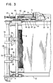
- Fig. 3 is an underneath view of part of the apparatus shown in Fig. 2;
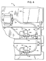
- Fig. 4 is a side view of part of the note picking apparatus showing means for applying reduced pressure to pick mechanisms of the apparatus;
- Figs. 5A and 5B are sectional views of a diaphragm pump incorporated in the note picking apparatus, these views showing different operational positions of operating parts of the pump;
- Fig. 6 is a circuit diagram of means for operating solenoid operated valves incorporated in the note picking apparatus;
- Fig. 7 is a schematic block diagram illustrating electrical interconnections between parts of the note picking apparatus; and
- Figs 8A to 8D are schematic views illustrating different stages in a cycle of operation of each of the pick mechanisms.
- Referring to Fig. 1, the
cash dispenser unit 10 shown therein includes twosimilar pick mechanisms 12 arranged one above the other and respectively associated with twocurrency cassettes 14 which are removably mounted in a supportingframework 16 of thedispenser 10. Each of thecassettes 14 is arranged to contain a stack ofcurrency notes 18, corresponding long edges of which are supported on ahorizontal support plate 20 mounted in thecassette 14. The twocassettes 14 respectively containnotes 18 of different denominations. - Referring now additionally to Figs. 2 and 3, the stack of
notes 18 in eachcassette 14 is urged by a spring loaded pusher member 22 (Fig. 1) towards a stop member 24 (Fig. 2) mounted at the front end (left hand end with reference to Figs. 1 to 3) of thecassette 14. An opening 26 (Fig. 2) is formed in the front end of eachcassette 14, the opening 26 being normally closed by conventional shutter means (not shown) when thecassette 14 is not mounted in thedispenser unit 10. When acassette 14 is mounted in its correct operational position in thedispenser unit 10, the relevant shutter means is automatically retracted away from its closed position so as to enablecurrency notes 18 to be extracted through theopening 26 by theassociated pick mechanism 12.Brushes 28 are provided at the front end of thesupport plate 20 of eachcassette 14 for a purpose which will be explained later. - Each
pick mechanism 12 includes atubular member 30 which extends between, and is rotatably mounted with respect to,side walls framework 16. Twoconventional pick arms 36, each incorporating arubber suction pad 38, are secured on eachtubular member 30, eachpick arm 36 communicating with the interior of the associatedtubular member 30. Corresponding ends of thetubular members 30 project beyond theside wall 34, and are each connected by a respectiveswivel elbow connector 40 to arespective rubber tube 42 having an internal diameter of 4 millimetres. It should be understood that theconnectors 40 provide substantially air-tight connections between thetubular members 30 and therubber tubes 42, while permitting pivotal movement of thetubular members 30 relative to theconnectors 40. - A
gear segment 44 is secured to that part of eachtubular member 30 projecting beyond theside wall 34, thegear segment 44 being in cooperative engagement with atoothed end portion 46 of a first arm of a respectivebell crank lever 48 which is pivotably mounted on astud 50 secured to the outer surface of thewall 34. Eachlever 48 is urged to rotate in an anticlockwise direction with reference to Fig. 2 by means of aspring 52 the ends of which are respectively attached to theside wall 34 and to the end of the second arm of thelever 48. Astud 54 is secured to one side of eachlever 48, thestud 54 engaging in acam track 56 formed in an associated cam member 58 (Fig. 3). Eachcam member 58 is secured to arespective gear wheel 60 which is rotatably mounted on arespective shaft 62 projecting from the outer surface of theside wall 34. Thegear wheels 60 are driven by agear mechanism 64 operated by a main drive electric motor 66 (Figs. 4, 5A, 5B and 7). In operation, with themotor 66 energized, thegear wheels 60 are rotated in a clockwise direction with reference to Fig. 2. This rotation of thegear wheels 60 brings about an oscillatory pivotal movement of thelevers 48 by virtue of the engagement of thestuds 54 in thecam tracks 56, thesprings 52 holding thestuds 54 in engagement with the inner edges of thecam tracks 56. By virtue of the engagement of thegear segments 44 with thetoothed portions 46 of thelevers 48, the oscillatory movement of thelevers 48 brings about an oscillatory pivotal movement of the assemblies of thetubular members 30 and the associatedpick arms 36 so as to cause eachpick arm 36 to move between the positions respectively shown in Fig. 2 and Fig. 8B. As will be explained in more detail later, the oscillatory movement of either of the assemblies of thetubular members 30 and associatedpick arms 36 is effective to pickcurrency notes 18 one by one from the stack ofcurrency notes 18 held in the associatedcurrency cassette 14. - A
timing disc 68 is secured to that face of eachgear wheel 60 remote from the associatedcam member 58. Eachtiming disc 68 is for the most part transparent but incorporates an arcuateopaque strip 70 extending around just over half the periphery of thedisc 68. Eachtiming disc 68 is associated with optical sensing means, comprising anLED 72 and a cooperatingphototransistor sensor 73 which is arranged to sense theopaque strip 70. In operation, as each assembly of agear wheel 60 and the associatedcam member 58 andtiming disc 68 rotates in response to energization of themotor 66, theassociated sensor 73 generates output signals in response to the sensing of the leading and trailing edges of the associatedopaque strip 70. It should be understood that the signals generated by each of thesensors 73 provide indications as to the precise positions of the associatedpick arms 36 at the times when these signals are generated. Also, it should be noted that one revolution of thetiering disc 68 corresponds to six revolutions of the drive shaft 160 (Figs. 5A and 5B) of theelectric motor 66, one revolution of thetiming disc 68 taking about 240 milliseconds. - Each
pick mechanism 12 also includes a first set ofrolls 74 secured on adrive shaft 76, and a second set of rolls 78 (hereinafter referred to as cam rolls) which are secured on adrive shaft 80 in cooperative relationship with respect to therolls 74, and whose peripheries compriselow portions 82 andhigh portions 84. Thedrive shafts side walls gear mechanism 64 so that in operation therolls 74 and thecam rolls 78 respectively rotate in clockwise and anticlockwise directions with reference to Fig. 2, therolls 74 and thecam rolls 78 making two revolutions for each revolution of thetiming discs 68. In the course of a pick operation, the lower long edge of thefirst currency note 18′ of the stack ofnotes 18 in therelevant cassette 14 is pulled partly out of thecassette 14 by therespective pick arms 36 and is fed between thelow portions 82 of therespective cam rolls 78 and the associatedrolls 74. Thenote 18′ is thereafter pulled completely out of thecassette 14 by virtue of being gripped between thehigh portions 84 of thecam rolls 78 and therolls 74. - The
cash dispenser unit 10 includes twonote transport mechanisms 86 respectively associated with the twopick mechanisms 12. Eachtransport mechanism 86 includes guide means 87 and sets offeed rolls associated pick mechanism 12 along arespective feed path 98 towards afurther transport mechanism 100 positioned above themechanisms 86. Thetransport mechanism 100 serves to feed currency notes one by one to aconventional stacking wheel 102. The sets ofcam rolls 78 and cooperatingrolls 74 of eachpick mechanism 12 feed a picked currency note to cooperating sets ofrolls rolls rolls respective transport mechanism 86. The upper one of thetransport mechanisms 86 additionally includes two further sets of cooperatingrolls 104 for accepting a currency note fed upwardly out of thelower transport mechanism 86 and for feeding this note to the cooperatingrolls upper mechanism 86, from where the note is fed to thetransport mechanism 100. Further optical sensing means comprising anLED 106 and a cooperatingphototransistor sensor 108 are mounted adjacent eachpick mechanism 12 for the purpose of sensing the leading edge of a picked currency note fed by the cooperatingrolls pick mechanism 12 to the cooperatingrolls respective transport mechanism 86. - Referring now particularly to Fig. 1, the
stacking wheel 102 is arranged to rotate continuously in operation in an anticlockwise direction. Means (not shown) are provided between theupper transport mechanism 86 and thestacking wheel 102 for detecting any multiple feeding of notes and for detecting any invalid or torn note. Thestacking wheel 102 comprises a plurality ofstacking plates 110 spaced apart in parallel relationship along thestacker wheel shaft 112, eachstacking plate 110 incorporating a series ofcurved tines 114. Thetines 114 of thestacking plates 110 pass betweenportions 116 of a rockably mountedstripper plate assembly 118. In operation, each note fed by thetransport mechanism 100 to the stackingwheel 102 enters betweenadjacent tines 114 and is carried partly around the axis of the stackingwheel 102, the note being stripped from thewheel 102 by theportions 116 and being stacked against belt means 120 with a long edge of the note resting on thestripper plate assembly 118. The belt means 120 cooperates with belt means 122 normally held in the position shown in Fig. 1. When a bundle ofnotes 18˝ (or possibly a single note only) to be dispensed to a user in response to a cash withdrawal request has been stacked against the belt means 120, the belt means 122 is rocked in a clockwise direction so as to trap the bundle ofnotes 18˝ between the belt means 120 and the belt means 122. It should be understood that in the course of this rocking movement separate belts making up the belt means 122 pass between adjacent pairs of the stackingplates 110. - Assuming that none of the notes in the
bundle 18˝ have been rejected for any reason, the belt means 120 and 122 are operated so as to drive thebundle 18˝ to a pair of drive belt means 126 and 128. The belt means 126 and 128 serve to drive thebundle 18˝ through anote exit slot 130 in ahousing 132 of the ATM to a position where thebundle 18˝ can be collected by the user of the ATM, ashutter 134 which serves to close theslot 130 when the ATM is not in operation having previously been retracted to an open position. It should be understood that the belt means 120 and 122 are mounted in resilient relationship relative to each other and the belt means 126 and 128 are also mounted in resilient relationship relative to each other, so that bundles of notes of varying thickness can be held between, and fed by, the belt means 120 and 122 and the belt means 126 and 128. If a multiple feeding has been detected in the course of stacking the bundle ofnotes 18˝ against the belt means 120, or if one or more of the notes in thebundle 18˝ have been rejected for any other reason, then thestripper plate assembly 118 is rocked into the position shown in chain outline in Fig. 1, and the belt means 120 and 122 are operated to feed thebundle 18˝ in a direction opposite to the normal feed direction, thebundle 18˝ being deposited in areject note container 136 via an opening in the top thereof. - Referring now additionally to Fig. 4, that end of each of the
rubber tubes 42 remote from the associatedswivel elbow connector 40 is connected to aninlet port 138 of a respective solenoid operatedvalve 140. A suitable valve for use as thevalve 140 is aseries 34 valve supplied by Webber Electro Components Limited of Bristol, England. Eachvalve 140 also has avent port 142, and anoutlet port 144 connected to arespective rubber tube 146 having an internal diameter of 6 millimetres. When thesolenoid 148 of eachvalve 140 is in a de-energized condition, theoutlet port 144 is closed and thevent port 142 is open, theinlet port 138 being connected to the atmosphere via thevent port 142. When thesolenoid 148 is in an energized condition, theoutlet port 144 is open and thevent port 142 is closed, theinlet port 138 communicating with the associatedrubber tube 146 via theoutlet port 144. Those ends of therubber tubes 146 remote from thevalves 140 are connected via aconnector 150 and afurther rubber tube 152 to aninlet port 154 of adiaphragm pump 156 which is operated by theelectric motor 66. It should be understood that, in operation, reduced pressure can be applied by thepump 156 to thetubular member 30 of a selected one of thepick mechanisms 12 by energization of thesolenoid 148 of the associatedvalve 140. - As shown in Figs 5A and 5B, the
pump 156 is operated by an eccentricallymounted shaft 158 driven by thedrive shaft 160 of themotor 66. The eccentricallymounted shaft 158 passes through, and is a rotatable fit with respect to, acentral opening 162 in ayoke 164, upper andlower portions yoke 164 being respectively connected to upper andlower rubber diaphragms upper rubber gasket 174 having integral flap valves 176 (Fig. 5A) and 178 (Fig. 5B) is mounted above theupper diaphragm 170, and alower rubber gasket 180 having integral flap valves 182 (Fig. 5B) and 184 (Fig. 5A) is mounted below thelower diaphragm 172. When theshaft 158 rotates through 180° from the position shown in Fig. 5B to the position shown in Fig. 5A, theflap valves flap valves diaphragm 170 drawing air into thepump 156 from theinlet port 154 via theflap valve 176, and thediaphragm 172 expelling air from afirst outlet vent 186 of thepump 156 via theflap valve 184. When theshaft 158 rotates through a further 180° from the position shown in Fig. 5A to the position shown in Fig. 5B, theflap valves flap valves diaphragm 172 drawing air into thepump 156 from theinlet port 154 via theflap valve 182, and thediaphragm 170 expelling air from asecond outlet vent 188 of thepump 156 via theflap valve 178. Thus, in operation, a reduced pressure is continuously generated at theinlet port 154 in response to rotation of theshaft 158. - Each
pick mechanism 12 is associated with a respective electrical circuit (Fig. 6) in which are included theLED 72 and thephototransistor 73 associated with thepick mechanism 12. The collector electrode of thephototransistor 73 is connected via aresistor 190 to a +5V voltage supply and is also connected to a first input terminal of acomparator 192, a second input terminal of which is connected to an intermediate point of a potential divider formed by tworesistors 194 connected between the +5V voltage supply and ground. In operation, when theopaque strip 70 of the associatedtiming disc 68 is interposed between theLED 72 and thephototransistor 73, the voltage at the collector of thephototransistor 73 goes high, thereby causing a high signal to appear on aline 196 connected to the output of thecomparator 192. Theline 196 is connected to a first input of an ANDgate 198, a second input of which is connected to aline 200 connected to electronic control means 202 (see also figs. 4 and 7) of thecash dispenser unit 10. The output of the ANDgate 198 is connected via aresistor 204 to the gate of atransistor 206. The collector of thetransistor 206 is connected to one terminal of thesolenoid 148 of the associatedvalve 140, the other terminal of thesolenoid 148 being connected to a +24V voltage supply. When the electronic control means 202 applies a high signal PICK to the ANDgate 198 over theline 200, the output of the ANDgate 198 goes high in response to the output of thecomparator 192 going high when the leading edge of the relevantopaque strip 70 is sensed by thephototransistor sensor 73. Upon the output of the ANDgate 198 going high, thetransistor 206 is turned on so as to energize thesolenoid 148. As previously explained, energization of thesolenoid 148 will cause reduced pressure to be applied to thetubular member 30 of the associatedpick mechanism 12 so that thesuction pads 38 will apply a suction force to thefirst note 18′ of the associated stack ofnotes 18. It should be understood that the electronic control means 202 applies a high signal PICK to theline 200 associated with the selectedpick mechanism 12 when therelevant sensor 73 is sensing a transparent portion of the associatedtiming disc 68. Thus, energization of thesolenoid 148 of the selectedpick mechanism 12 is always initiated by the sensing of the leading edge of theopaque strip 70 of the associatedtiming disc 68. - The operation of the
cash dispenser unit 10 will now be described with additional reference to Fig. 7 and Figs. 8A to 8D. This operation is controlled by the electronic control means 202. When the main ATM processor (not shown) sends a request to the electronic control means 202 that one or more currency notes are to be dispensed by thedispenser unit 10 in response to a cash withdrawal request by a user of the ATM, the control means 202 sends a signal to themotor 66 so as to switch on themotor 66 and cause the assemblies of thegear wheels 60,cams 58 andtiming discs 68 to commence to rotate. After a delay of 250 milliseconds (which corresponds to slightly more than one revolution of eachtiming disc 68, or six revolutions of thedrive shaft 160 of the motor 66), the control means 202 applies a high signal PICK over therelevant line 200 to the ANDgate 198 associated with a selected one of thepick mechanisms 12. Upon thephototransistor 73 sensing the leading edge of theopaque strip 70 of thetiming disc 68 of the selectedpick mechanism 12 with a high signal present on theline 200, the output of the ANDgate 198 goes high so as to energize thesolenoid 148 of therelevant valve 140. - At this time, the
timing disc 68 and thepick arms 36 of the selectedpick mechanism 12 are in the positions shown in Fig. 8A, thesuction pads 38 having just come into contact with thefirst note 18′ of the stack ofnotes 18 held in the associatedcassette 14 in the course of a pivotal movement of thepick arms 36 in an anticlockwise direction. Thesuction pads 38 form a seal with thefirst note 18′, and since therelevant solenoid 148 has been energized so as to cause thepump 156 to apply a reduced pressure to therelevant tubular member 30, suction is applied by thesuction pads 38 to thefirst note 18′. Thereafter, thepick arms 36 continue to pivot a short amount in an anticlockwise direction. The positions of thepick arms 36 and thetiming disc 68 at the end of this pivotal movement are as shown in Fig. 8B, thepick arms 36 having pushed thefirst note 18′ a short distance into the interior of the associatedcassette 14. By this time, the seal between thesuction pads 38 and thefirst note 18′ has been consolidated by virtue of the suction force applied to thefirst note 18′ by thesuction pads 38 continuing to build up as thephototransistor 73 continues to sense theopaque strip 70 of thetiming disc 68. Typically, at this time the reduced pressure applied to thesuction pads 38 is about half an atmosphere. - Next, in response to continued rotational movement of the
relevant gear wheel 60, thepick arms 36 undergo a pivotal movement in a clockwise direction until they reach the position shown in Fig. 8C. During this pivotal movement, thephototransistor 73 continues to sense theopaque strip 70 so that reduced pressure continues to be applied to thesuction pads 38 via thetubular member 30. Because of this applied reduced pressure, thepick arms 36 apply a suction force to thefirst note 18′ so as to pull the lower part of thenote 18′ out of the associatedcassette 14 until the lower end of thenote 18′ comes into contact with the set ofrolls 74 as shown in Fig. 8C. It should be understood that, as the lower end of thenote 18′ is approaching therolls 74, thelow portions 82 of the cam rolls 78 are facing therolls 74 so that the cam rolls 78 do not interfere with the movement of thenote 18′. At the stage of operation of therelevant pick mechanism 12 illustrated in Fig. 8C, the trailing end of theopaque strip 70 has reached thephototransistor 73 thereby causing therelevant solenoid 148 to become de-energized so that reduced pressure ceases to be applied to thesuction pads 38. Accordingly, at this time thesuction pads 38 become disengaged from thenote 18′, while at the same time thehigh portions 84 of the cam rolls 78 are about to come into cooperative relationship with therolls 74. Shortly after thenote 18′ becomes disengaged from thesuction pads 38, thenote 18′ is gripped between therolls 74 and thehigh portions 84 of the cam rolls 78 as shown in Fig. 8D. Therolls note 18′ away from therespective cassette 14 until the leading edge of thenote 18′ enters the nip of therolls transport mechanism 86, after which thenote 18′ is pulled completely out of thecassette 14 and fed to the stackingwheel 102 in the manner previously described. - After the
note 18′ has been fed to the nip of therolls relevant line 200 goes low so that no further reduced pressure is applied to thesuction pads 38 until such time as a further signal PICK is applied by the electronic control means 202 to the relevant ANDgate 198 over theline 200. It should be understood that, for the whole of the time that thenote 18′ is gripped between therolls phototranistor 73 is sensing the transparent part of thetiming disc 68 so that reduced pressure is not applied to thesuction pads 38. After thenote 18′ has been fed to the stackingwheel 102, the electronic control means 202 may cause a series of further pick operations to be carried out in each of which a currency note is picked from one or other of thecassettes 14 in response to the application of a signal PICK to the appropriate ANDgate 198. The electronic control means 202 monitors the outputs of the two pickednote sensors 108 every 3 milliseconds during a pick operation, and by monitoring these outputs the control means 202 ascertains when the correct number and denomination of notes, in accordance with the cash withdrawal request made by the user of the ATM, have been picked from thecassettes 14. Upon the control means 202 ascertaining that the correct number and denomination of currency notes have been picked from thecassettes 14, the control means 202 returns thecash dispenser unit 10 to its quiescent condition by de-energizing themotor 66 and holding the voltages on thelines 200 at a low level. When these last-mentioned voltages are at a low level, both thesolenoids 148 are held in a de-energized condition, with theinlet ports 138 of thevalves 140 being disconnected from theoutlet ports 144 and being connected to the atmosphere via thevent ports 142. With thecash dispenser unit 10 in its quiescent condition, thepick arms 36 of each of thepick mechanisms 12 are in the position shown in Fig. 2 in which they are fully retracted with respect to the stack ofnotes 18 held in the associatedcassette 14. - When the
first note 18′ is being picked from the associatedcassette 14, it is possible, due to a certain amount of porosity of thefirst note 18′, for the second note of the stack ofnotes 18 to commence to be drawn away from the remainder of the stack together with thefirst note 18′. Thebrushes 28 will normally prevent the second note being drawn out of thecassette 14 together with thefirst note 18′, since, in the event of the first and second notes commencing to be drawn out of thecassette 14, thebrushes 28 flex the lower ends of these notes, thereby interrupting the application of suction force to the second note and so permitting the second note to fall back into its correct position in thecassette 14. - With reference to Fig. 7, the
cash dispenser unit 10 includes in the vicinity of the pick mechanisms 12 a temperature indicating means 208 having an output connected to the electronic control means 202. In operation, there appears on the output of the temperature indicating means 208 a signal indicative of the temperature in the interior of theunit 10. If the temperature indicated by the indicating means 208 is below a predetermined minimum temperature specification stored in the control means 202, then, following the initiation of a pick operation, the control means 202 applies a signal PICK to the relevant ANDgate 198 after a delay of 500 milliseconds following the energization of themotor 66, compared with a normal delay of 250 milliseconds if the indicated temperature is at or above the minimum temperature specification. This increased delay enables a stronger vacuum (ie. pressure reduced more than normal) to be built up in thetubes 146 connected to theoutlet ports 144 of thevalves 140 by the time the signal PICK is applied to the relevant ANDgate 198, so that a stronger suction force is applied by therelevant suction pads 38 to thefirst note 18′ in the associatedcassette 14 when therelevant solenoid 148 is energized. This increased suction force compensates for the fact that as thesuction pads 38 are at a lower temperature than normal they are less flexible than normal and
so require to apply a stronger suction force in order to make an effective seal with thefirst note 18′. - If, following the initiation of a pick operation, the output of the relevant note picked
sensor 108 indicates that no note has been picked and fed to the stackingwheel 102 within a predetermined time, then the electronic control means 202 determines that there has been a pick failure. When the control means 202 determines that there has been a pick failure, the control means 202 terminates the current pick operation, by de-energizing themotor 66 and terminating the signal PICK on therelevant line 200, and then initiates a first retry pick operation. In the first retry pick operation, the control means 202 applies a signal PICK to the relevant ANDgate 198 after a delay of 1.2 seconds following the energization of themotor 66. Accordingly, in the first retry pick operation, a stronger vacuum will be applied to therelevant suction pads 38 compared with the vacuum which was applied in the pick operation which resulted in pick failure. As a result, a stronger suction force will be applied by therelevant suction pads 38 to thefirst note 18′ so that there is a good possibility that the first retry pick operation will be successful, resulting in thefirst note 18′ being picked from therelevant cassette 14 and fed to the stackingwheel 102. - If the first retry pick operation is not successful, then the control means 202 will initiate a second retry pick operation. In the second retry pick operation, the control means 202 applies a signal PICK to the relevant AND
gate 198 after a delay of 10 seconds following the energization of themotor 66 so that an even stronger vacuum will be applied to therelevant suction pads 38. Thus, even though the first retry pick operation was unsuccessful, there is a reasonable chance that the second retry pick operation will be successful. If the second retry pick operation is unsuccessful, the control means 202 will initiate a third retry pick operation, again using a delay of ten seconds, and if the third retry pick operation is unsuccessful the control means 202 will render therelevant pick mechanism 12 non-operational and will generate a signal to the effect that thispick mechanism 12 requires attention by bank or service personnel. - Possible causes of a pick failure are that the
first note 18′ has become excessively porous through long usage, or that, in the region of thefirst note 18′ where thesuction pads 38 make contact, thenote 18′ is folded or torn or has holes therein, so that an effective vacuum seal is not established at the surface of thenote 18′. If a pick failure occurs due to such defect in thefirst note 18′, then, when a stronger vacuum is applied by thesuction pads 38 to thefirst note 18′ in the course of a retry pick operation, it is possible for a strong suction force to be applied through thefirst note 18′ to the next note in the stack, resulting in both notes being drawn out of therelevant cassette 14, this suction force being effective to overcome the action of thebrushes 28. The two notes thus drawn out of thecassette 14 and fed to the stackingwheel 102 will be detected by the multiple feeding detect means (not shown) previously referred to and will be deposited in thereject note container 136. The defective note having been cleared from therelevant cassette 14, normal picking of notes from thiscassette 14 can now be resumed. - If one of the note picked
sensors 108 provides an indication to the control means 202 that a note has been left interposed between theLED 106 and thesensor 108, possibly as a result of a jam occurring in therelevant pick mechanism 12, then this is another situation where the control means 202 will render thepick mechanism 12 non-operational and will generate a signal to the effect that thispick mechanism 12 requires attention by bank or service personnel. - The note picking apparatus described above has the advantage that it is highly reliable in operation. One reason for this reliability is that the
diaphragm pump 156 continuously applies a reduced pressure to thesuction pads 38 of thepick arms 36 of the selectedpick mechanism 12 during the whole of the relevant pivotal movement of thepick arms 36, thereby substantially avoiding the risk of theend note 18′ dropping off thepick arms 36 during this movement. In contrast, in operation of a known vacuum operated note picking apparatus in which a piston vacuum pump is used as the vacuum source, the suction force generated by the pump decays to zero during each cycle of the pump so that precise mechanical timing must be maintained to ensure that an adequate reduced pressure is applied to the suction pads of the pick arms of the selected pick mechanism during the whole of the relevant pivotal movement of the pick arms. - Another important reason for the reliability of the note picking apparatus described above is that for each
pick mechanism 12 there is used an electrically operatedvalve 140 for controlling the application of suction force to thesuction pads 38 of therelevant pick arms 36, operation of thevalve 140 being controlled by signals from timing means (timing disc 68) which rotates in synchronism with the oscillatory movement of thepick arms 36, so that the timing signals provide an indication of the position of thepick arms 36 relative to the associatedcassette 14. Thus, eachtiming disc 68 represents a simple means for ensuring that a suction force is always applied to, and removed from, thefirst note 18′ in the relevant stack at the correct times. In addition, as explained hereinbefore, the electrically operatedvalves 140 enable the application of reduced pressure to thesuction pads 38 of a selectedpick mechanism 12 to be delayed by different amounts in response to changing operational requirements. Thus, the electrically operatedvalves 140 enable an increased suction force to be applied to theend note 18′ of a stack from time to time, as may be required, for example, in the event of a pick failure occurring, or in the event of the temperature in the interior of thecash dispenser unit 10 falling below a predetermined minimum temperature specification. Also, the use of the electrically operatedvalves 140 makes it possible for the electronic control means 202 to decrease the suction force, for example in the event that it is found that there is a tendency for two notes to be picked in the course of a pick operation. As a result of this ability to vary the applied suction force, the reliability of the note picking apparatus described above is significantly enhanced compared with known note picking apparatuses. - The reliability of the note picking apparatus described above is also enhanced by virtue of the fact that the internal diameters of the connecting
tubes 146 on the pump side of thevalves 140 is greater than the internal diameters of the connectingtubes 42 connected to thetubular members 30, since this arrangement enables a suction force to become available at thesuction pads 38 of the selectedpick mechanism 12 within a very short time interval after the opening of the associatedvalve 140. - In a modified version of the note picking apparatus described above, instead of the
diaphragm pump 156 there could be used a vane pump which, in operation, also continuously generates a reduced pressure at an inlet port thereof.
Claims (7)
- A sheet separating apparatus for removing sheets one by one from a stack of sheets (18) held in a container (14), including pump means (156) for continuously generating a reduced pressure in operation, suction means (36) connectable to said pump means and pivotably movable between first and second positions, said suction means serving, when moved from said first position to said second position, to withdraw part of an end sheet (18′) of said stack away from the remainder of said stack by applying a suction force to said end sheet, and to position said part for engagement by transport means (74,78,86) arranged to remove said end sheet from said container (14), valve means (140) for connecting said pump means (156) to said suction means (36), and timing means (68,73) responsive to the position of said suction means (36) relative to said container (14) and serving to control the operation of said valve means (140) whereby said pump means communicates with said suction means during movement of said suction means from said first position to said second position, characterized in that said valve means (140) is electrically operated, and said timing means (68,73) generates timing signals indicative of the position of said suction means (36) relative to said container (14), said timing signals serving to control the operation of said valve means, and in that the apparatus includes electronic control means (202) arranged, during a sheet picking operation, to initiate operation of said pump means (156) and subsequently to enable said valve means (140) to be operated by a timing signal generated by said timing means (68, 73) and to vary the time interval between the operation of said pump means (156) and the operation of said valve means (140), whereby the suction force applied by said suction means (36) to said end sheet (18′) may be varied.
- An apparatus according to claim 1, characterized by electrical temperature indicating means (208) for indicating the temperature of the interior of the apparatus in the vicinity of said suction means (36), the output of said temperature indicating means (208) being connected to said electronic control means (202), and said time interval being arranged to be varied by said electronic control means in dependence on the temperature indicated by said temperature indicating means.
- An apparatus according to either claim 1 or claim 2, characterized by sheet picked sensing means (108) arranged to sense whether a sheet has been successfully picked from said container (14) during a sheet picking operation, the output of said sheet picked sensing means being connected to said electronic control means (202), and said electronic control means (202) being arranged to initiate a first retry pick operation in the event that said sheet picked sensing means (108) provides an indication that a sheet has not been successfully picked from said container, said electronic control means being arranged to increase said time interval in said first retry pick operation compared with said time interval in the immediately preceding unsuccessful pick operation.
- An apparatus according to claim 3, characterized in that said electronic control means (202) is arranged to initiate a second retry pick operation in the event that said sheet picked sensing means (108) provides an indication that a sheet has not been successfully picked from said container (14) during said first retry pick operation, said electronic control means being arranged to increase said time interval in said second retry pick operation compared with said time interval in said first retry pick operation.
- An apparatus according to any one of said preceding claims, characterized in that said valve means (140) includes a first port (138) connected via first tube means (42) to said suction means (36), a second port (144) connected via second tube means (146) to said pump means (156), and a third port (142) connected to the atmosphere, said first port communicating with said second port and said third port being closed when said valve means (140) is in an operated condition, and said first port communicating with said third port and said second port being closed when said valve means is in a non-operated condition.
- An apparatus according to claim 5, characterized in that the internal diameter of said second tube means (146) is greater than the internal diameter of said first tube means (42).
- An apparatus according to any one of the preceding claims, characterized by gate means (198) to a first input of which timing signals from said timing means (68,73) are applied during a sheet picking operation, and to a second input of which an enabling signal from said electronic control means (202) is applied during a sheet picking operation, the output of said gate means (198) serving to control the operation of said valve means (140).
Applications Claiming Priority (2)
| Application Number | Priority Date | Filing Date | Title |
|---|---|---|---|
| GB9006542 | 1990-03-23 | ||
| GB909006542A GB9006542D0 (en) | 1990-03-23 | 1990-03-23 | Sheet separating apparatus |
Publications (3)
| Publication Number | Publication Date |
|---|---|
| EP0448385A2 EP0448385A2 (en) | 1991-09-25 |
| EP0448385A3 EP0448385A3 (en) | 1991-10-16 |
| EP0448385B1 true EP0448385B1 (en) | 1995-08-23 |
Family
ID=10673131
Family Applications (1)
| Application Number | Title | Priority Date | Filing Date |
|---|---|---|---|
| EP91302444A Expired - Lifetime EP0448385B1 (en) | 1990-03-23 | 1991-03-20 | Sheet handling apparatus |
Country Status (5)
| Country | Link |
|---|---|
| US (1) | US5112040A (en) |
| EP (1) | EP0448385B1 (en) |
| CA (1) | CA2032775C (en) |
| DE (1) | DE69112246T2 (en) |
| GB (1) | GB9006542D0 (en) |
Families Citing this family (12)
| Publication number | Priority date | Publication date | Assignee | Title |
|---|---|---|---|---|
| GB9517796D0 (en) * | 1995-08-31 | 1995-11-01 | At & T Global Inf Solution | A bank note scanner |
| GB9518346D0 (en) * | 1995-09-08 | 1995-11-08 | At & T Global Inf Solution | Sheet separating apparatus |
| GB9525106D0 (en) * | 1995-12-08 | 1996-02-07 | At & T Global Inf Solution | Sheet separating apparatus |
| US5871209A (en) * | 1996-03-01 | 1999-02-16 | Currency Systems International, Inc. | Cassette based document handling system |
| US5996314A (en) * | 1996-05-22 | 1999-12-07 | Currency Systems International, Inc. | Currency strapping machine |
| GB9611344D0 (en) * | 1996-05-31 | 1996-08-07 | Ncr Int Inc | Improved transaction terminal |
| SE9803616D0 (en) * | 1998-10-22 | 1998-10-22 | Nybohov Dev Ab | Banknote Handling Machine |
| JP3863412B2 (en) * | 2001-11-16 | 2006-12-27 | 東北リコー株式会社 | Paper feeder / printer |
| WO2005098767A1 (en) * | 2004-03-29 | 2005-10-20 | Streamline Innovations Gmbh | Note validating and storage assembly and method |
| GB0427693D0 (en) * | 2004-12-17 | 2005-01-19 | Ncr Int Inc | An automated teller machine |
| US20070023500A1 (en) * | 2005-07-29 | 2007-02-01 | Deraedt Peter W | Note validating and storage assembly and method |
| JP4950812B2 (en) * | 2007-08-29 | 2012-06-13 | 株式会社東芝 | Paper sheet take-out device |
Family Cites Families (14)
| Publication number | Priority date | Publication date | Assignee | Title |
|---|---|---|---|---|
| US4090702A (en) * | 1972-04-26 | 1978-05-23 | Heidelberger Druckmaschinen Ag | Suction air control device for use with sheet feeds |
| JPS5273468A (en) * | 1975-12-16 | 1977-06-20 | Oki Electric Ind Co Ltd | Feeding system for sort of paper |
| DK151867C (en) * | 1978-02-07 | 1988-06-27 | Malmoehus Invest Ab | TRANSPORT MODULE FOR TRANSPORT AND CREATION OF FLEXIBLE, EQUIPPING MATERIALS |
| CH626589A5 (en) * | 1978-02-15 | 1981-11-30 | Ferag Ag | |
| JPS5748543A (en) * | 1980-09-04 | 1982-03-19 | Laurel Bank Mach Co Ltd | Attraction and drawing-out apparatus of paper sheet processing machine |
| DE3211610C2 (en) * | 1982-03-30 | 1985-04-18 | Agfa-Gevaert Ag, 5090 Leverkusen | Device for removing a sheet from a stack |
| US4591140A (en) * | 1983-03-12 | 1986-05-27 | Agfa-Gevaert Aktiengesellschaft | Arrangement for separating and transporting uppermost sheets of a stack of sheets or sheet-like objects |
| US4709991A (en) * | 1983-04-26 | 1987-12-01 | Seiko Epson Kabushiki Kaisha | Liquid crystal display with barrier layer to reduce permeability |
| US4513957A (en) * | 1983-05-03 | 1985-04-30 | Ncr Corporation | Item dispensing system |
| US4524691A (en) * | 1984-01-11 | 1985-06-25 | Graphic Arts Technical Innovators, Inc. | Envelope feeder for printing press with timing circuit for suction cups, feed roller and flywheel |
| US4712784A (en) * | 1985-05-31 | 1987-12-15 | Rca Corporation | Adjustable vacuum pad |
| JPH0823665B2 (en) * | 1985-12-02 | 1996-03-06 | 株式会社東芝 | Sheet film transport device |
| US4730823A (en) * | 1986-11-28 | 1988-03-15 | International Business Machines Corporation | Adaptive document feed pick mechanism |
| JPH01181636A (en) * | 1988-01-13 | 1989-07-19 | Seiko Instr & Electron Ltd | Paper transfer unit for image recording device |
-
1990
- 1990-03-23 GB GB909006542A patent/GB9006542D0/en active Pending
- 1990-07-26 US US07/557,817 patent/US5112040A/en not_active Expired - Lifetime
- 1990-12-20 CA CA002032775A patent/CA2032775C/en not_active Expired - Fee Related
-
1991
- 1991-03-20 EP EP91302444A patent/EP0448385B1/en not_active Expired - Lifetime
- 1991-03-20 DE DE69112246T patent/DE69112246T2/en not_active Expired - Fee Related
Also Published As
| Publication number | Publication date |
|---|---|
| GB9006542D0 (en) | 1990-05-23 |
| CA2032775C (en) | 1995-01-17 |
| US5112040A (en) | 1992-05-12 |
| DE69112246T2 (en) | 1996-04-18 |
| EP0448385A3 (en) | 1991-10-16 |
| DE69112246D1 (en) | 1995-09-28 |
| EP0448385A2 (en) | 1991-09-25 |
Similar Documents
| Publication | Publication Date | Title |
|---|---|---|
| US5719383A (en) | Transaction terminal and method of maintaining acceptable operation of the transaction terminal | |
| EP0448385B1 (en) | Sheet handling apparatus | |
| US5183140A (en) | Torque limiting mechanism for use in a drive system | |
| US5597996A (en) | Cash dispensing apparatus (ATM) and method for separating rejected bank notes | |
| EP0616963B1 (en) | Sheet handling apparatus | |
| EP0499458B1 (en) | Sheet handling apparatus | |
| US11945672B2 (en) | Single item removal | |
| US5110105A (en) | Sheet handling apparatus | |
| JPS6139259B2 (en) | ||
| US4739982A (en) | Sheet separating apparatus | |
| CA2046568A1 (en) | Torque limiting mechanism for use in a drive system | |
| US4516899A (en) | Sheet feeding apparatus | |
| EP0486251B1 (en) | Sheet handling apparatus | |
| JP3114144B2 (en) | Sheet separation device | |
| EP0486252B1 (en) | Torque limiting mechanism for use in a drive system | |
| JPS586838Y2 (en) | Paper sheet stacking device | |
| JPH09202466A (en) | Sheet separator | |
| JP3219431B2 (en) | Sheet handling equipment | |
| KR20000025371A (en) | Apparatus and method for detecting note remaining amount in cash automatic dispenser | |
| US20070139524A1 (en) | Method of determining the cause of an error state in an apparatus | |
| EP0810561A1 (en) | Improved transaction terminal | |
| JPH04302079A (en) | Paper handling apparatus | |
| JPS5842915B2 (en) | Jidouyokinki | |
| JPH04352087A (en) | Torque restricting mechanism used for driving system |
Legal Events
| Date | Code | Title | Description |
|---|---|---|---|
| PUAI | Public reference made under article 153(3) epc to a published international application that has entered the european phase |
Free format text: ORIGINAL CODE: 0009012 |
|
| PUAL | Search report despatched |
Free format text: ORIGINAL CODE: 0009013 |
|
| AK | Designated contracting states |
Kind code of ref document: A2 Designated state(s): DE FR GB |
|
| AK | Designated contracting states |
Kind code of ref document: A3 Designated state(s): DE FR GB |
|
| 17P | Request for examination filed |
Effective date: 19920312 |
|
| 17Q | First examination report despatched |
Effective date: 19940518 |
|
| RAP1 | Party data changed (applicant data changed or rights of an application transferred) |
Owner name: NCR INTERNATIONAL INC. |
|
| RAP1 | Party data changed (applicant data changed or rights of an application transferred) |
Owner name: AT&T GLOBAL INFORMATION SOLUTIONS INTERNATIONAL IN |
|
| GRAA | (expected) grant |
Free format text: ORIGINAL CODE: 0009210 |
|
| AK | Designated contracting states |
Kind code of ref document: B1 Designated state(s): DE FR GB |
|
| REF | Corresponds to: |
Ref document number: 69112246 Country of ref document: DE Date of ref document: 19950928 |
|
| ET | Fr: translation filed | ||
| PLBE | No opposition filed within time limit |
Free format text: ORIGINAL CODE: 0009261 |
|
| STAA | Information on the status of an ep patent application or granted ep patent |
Free format text: STATUS: NO OPPOSITION FILED WITHIN TIME LIMIT |
|
| 26N | No opposition filed | ||
| REG | Reference to a national code |
Ref country code: FR Ref legal event code: CD |
|
| REG | Reference to a national code |
Ref country code: GB Ref legal event code: IF02 |
|
| PGFP | Annual fee paid to national office [announced via postgrant information from national office to epo] |
Ref country code: GB Payment date: 20021220 Year of fee payment: 13 |
|
| PGFP | Annual fee paid to national office [announced via postgrant information from national office to epo] |
Ref country code: FR Payment date: 20030129 Year of fee payment: 13 |
|
| REG | Reference to a national code |
Ref country code: GB Ref legal event code: 746 Effective date: 20030114 |
|
| PGFP | Annual fee paid to national office [announced via postgrant information from national office to epo] |
Ref country code: DE Payment date: 20030310 Year of fee payment: 13 |
|
| REG | Reference to a national code |
Ref country code: FR Ref legal event code: D6 |
|
| PG25 | Lapsed in a contracting state [announced via postgrant information from national office to epo] |
Ref country code: GB Free format text: LAPSE BECAUSE OF NON-PAYMENT OF DUE FEES Effective date: 20040320 |
|
| PG25 | Lapsed in a contracting state [announced via postgrant information from national office to epo] |
Ref country code: DE Free format text: LAPSE BECAUSE OF NON-PAYMENT OF DUE FEES Effective date: 20041001 |
|
| GBPC | Gb: european patent ceased through non-payment of renewal fee |
Effective date: 20040320 |
|
| PG25 | Lapsed in a contracting state [announced via postgrant information from national office to epo] |
Ref country code: FR Free format text: LAPSE BECAUSE OF NON-PAYMENT OF DUE FEES Effective date: 20041130 |
|
| REG | Reference to a national code |
Ref country code: FR Ref legal event code: ST |