EP0447531B1 - Process and device for the three-dimensional optical measurement, especially of teeth in patients' buccal cavities - Google Patents
Process and device for the three-dimensional optical measurement, especially of teeth in patients' buccal cavities Download PDFInfo
- Publication number
- EP0447531B1 EP0447531B1 EP90915117A EP90915117A EP0447531B1 EP 0447531 B1 EP0447531 B1 EP 0447531B1 EP 90915117 A EP90915117 A EP 90915117A EP 90915117 A EP90915117 A EP 90915117A EP 0447531 B1 EP0447531 B1 EP 0447531B1
- Authority
- EP
- European Patent Office
- Prior art keywords
- partial views
- probe
- optical systems
- light
- light source
- Prior art date
- Legal status (The legal status is an assumption and is not a legal conclusion. Google has not performed a legal analysis and makes no representation as to the accuracy of the status listed.)
- Expired - Lifetime
Links
Images


Classifications
-
- G—PHYSICS
- G01—MEASURING; TESTING
- G01S—RADIO DIRECTION-FINDING; RADIO NAVIGATION; DETERMINING DISTANCE OR VELOCITY BY USE OF RADIO WAVES; LOCATING OR PRESENCE-DETECTING BY USE OF THE REFLECTION OR RERADIATION OF RADIO WAVES; ANALOGOUS ARRANGEMENTS USING OTHER WAVES
- G01S17/00—Systems using the reflection or reradiation of electromagnetic waves other than radio waves, e.g. lidar systems
- G01S17/88—Lidar systems specially adapted for specific applications
- G01S17/89—Lidar systems specially adapted for specific applications for mapping or imaging
-
- A—HUMAN NECESSITIES
- A61—MEDICAL OR VETERINARY SCIENCE; HYGIENE
- A61C—DENTISTRY; APPARATUS OR METHODS FOR ORAL OR DENTAL HYGIENE
- A61C13/00—Dental prostheses; Making same
- A61C13/0003—Making bridge-work, inlays, implants or the like
-
- A—HUMAN NECESSITIES
- A61—MEDICAL OR VETERINARY SCIENCE; HYGIENE
- A61C—DENTISTRY; APPARATUS OR METHODS FOR ORAL OR DENTAL HYGIENE
- A61C9/00—Impression cups, i.e. impression trays; Impression methods
- A61C9/004—Means or methods for taking digitized impressions
- A61C9/0046—Data acquisition means or methods
- A61C9/0053—Optical means or methods, e.g. scanning the teeth by a laser or light beam
-
- G—PHYSICS
- G01—MEASURING; TESTING
- G01B—MEASURING LENGTH, THICKNESS OR SIMILAR LINEAR DIMENSIONS; MEASURING ANGLES; MEASURING AREAS; MEASURING IRREGULARITIES OF SURFACES OR CONTOURS
- G01B11/00—Measuring arrangements characterised by the use of optical techniques
- G01B11/24—Measuring arrangements characterised by the use of optical techniques for measuring contours or curvatures
Definitions
- the invention relates to a method and a device for three-dimensional optical measurement of surfaces or bodies, in particular teeth or groups of teeth in the oral cavity of patients, according to the preambles of claims 1 and 4 to 6.
- Such a device is known from EP-A1 0278 882, which measures the surface of teeth by means of a so-called triangulation method for the purpose of producing dental prostheses.
- a stripe pattern is projected onto the tooth to be measured and this is then viewed from a parallax angle.
- the topography of the measured tooth can be calculated from the deformations of the stripe pattern observed.
- the so-called Cerec system from Siemens also uses the triangulation process to deal with the computer-assisted production of ceramic inlays for teeth.
- a tooth or group of teeth is measured in that the dentist manually positions the probe within the patient's oral cavity one after the other in different positions relative to the tooth in order to record overlapping partial views of the tooth, which are then combined into one by means of the computer Overall picture. Due to its manual handling by the dentist, the probe is in indefinite positions during the acquisition of the various partial views, which are not in a defined relationship to each other. As a result, the individual partial views can only be put together to form an overall picture that correctly represents the topography of the measured tooth if calibration bodies are fastened in the oral cavity or on the teeth of the patient in such a way that they can be measured with each partial view in order for the computer to determine the correct one Allow the individual partial views to be assigned to one another.
- this object is achieved in that the illumination of the individual partial views and the recording of the respectively reflected light patterns is carried out: either successively by means of the at least two optics, which for this purpose are successively shifted within the probe into defined positions assigned to the individual partial views be, or at the same time or in succession with more than two optics, which are fixed within the probe in fixed positions assigned to the individual partial views, the probe being held in a single position and thus defined with respect to the mutual association of the individual partial views.
- the principle of triangulation is preferably used, whereby a stripe pattern is projected onto the individual partial views by means of one lens and the stripe pattern reflected in each case, deformed in accordance with the topography of the measured partial view, is recorded and used as the basis for generating the electrical data signals .
- the advantages of this triangulation method compared to the interferometric moiré method include in that no coherent light is required and no speckle patterns occur.
- the phase shift principle is used, in which a stripe pattern with a brightness distribution that can be represented by a sine curve, each with a different phase, is projected onto each partial view at least three times and the reflected stripe pattern is recorded. Since the equation of each sinusoid contains three unknowns, namely the basic brightness, the brightness contrast and the phase of the respective wavefront, the three recordings used serve to determine the phase sought, with the same phases representing points of the same height on the measured body.
- the advantage over the static strip pattern projecting method lies in the continuous, areal information in contrast to discrete contour lines. This enables resolutions to be achieved that are in the range of a few micrometers.
- a device In order to carry out the method variant with simultaneous illumination of the individual partial views and the recording of the respectively reflected light pattern, a device is provided in which the number of the two optics assigned to each other at a fixed distance is equal to the number of partial views and their arrangement within the probe is fixed and the same mutual arrangement of Is partial views, wherein one of the two optics assigned to each other in pairs is connected to the light source and the other to the image sensor.
- a device in which the number of optics is equal to the number of partial views and their arrangement within the probe is fixed and the mutual arrangement of the partial views is the same, a multiplexer for pairwise simultaneous connection of two optics to the light source or to the image sensor is provided. Either adjacent or non-adjacent optics can be provided for this connection.
- the successive illumination of the individual partial views and the recording of the respectively reflected strip pattern can be carried out according to the third method variant with a device in which the at least two optics assigned to one another at a fixed distance in defined steps corresponding to the width of the partial views within the probe along a path the mutual arrangement of the partial views associated path can be moved and connected to the light source or to the image sensor via a multiplexer.
- the optics are preferably arranged or displaceable along a circular path or a cylindrical path.
- the light source and the image sensor are expediently arranged outside the probe.
- an LCD matrix light modulator is arranged between the light source and the probe for generating a stripe pattern for projection onto the individual partial views.
- An arrangement of the light source in a video projector is favorable.
- the multiplexer is preferably an optical muliplexor with a prism and / or mirror arrangement.
- the optical multiplexer can be connected to the light source or the image sensor via optical phase cables.
- the image sensor is preferably a CCD camera.
- the probe is used to project the light is formed in and for receiving the reflected light patterns from opposite directions.
- the computer comprises means for converting the electrical data signals into coordinates.
- the coordinates can be spherical coordinates, for example for the measurement of a single tooth, or cylindrical coordinates, for example for the measurement of groups of teeth.
- Such co-ordinates ensure that overlapping measuring surfaces can be averaged in such a way that they merge into one another largely without paragraphs. In this way, ambiguities in the measurements are excluded.
- the computer comprises a matrix memory for storing the coordinates.
- the light source is expediently a color light source or at least one color field is connected downstream of it. If, for example, a red filter or red light is used, a clear distinction can be made, for example, between the red gums and the white teeth when measuring teeth.
- the device shown in FIG. 1 comprises an oral probe 1 that can be inserted into the oral cavity of a patient, a video projector 2 with a light source 3 in the form of an incandescent lamp, a red filter 4 and an LCD matrix light modulator 5, both of which are arranged in the beam path of the projector , an image sensor 6 in the form of a CCD camera, a computer 7 and an optical fiber cable connection 8 between the mouth probe 1 and the video projector 2 and the CCD camera 6.
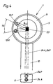
- the mouth probe 1, shown enlarged in FIG. 4, consists of a probe part 9 and a handle part 10.
- the probe part 9 comprises a rotating ring 11, which can be rotated step by step by means of a program-controlled rotary drive (not shown), in which two micro-optics of identical design in the form of a lens 12 each with a fixed, however, adjustable angular distance 13 are arranged.
- One of the lenses serves as a taking lens 12A and the other projection lens 12P.
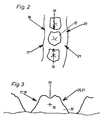
- the rotating ring 11 can be rotated step by step in each case by a defined angular amount 14 in preferably six defined positions. Six positions are selected because it is advantageous for complete three-dimensional measurement of a tooth 15 to take six partial views 16-21 from obliquely above, as shown in FIGS. 2 and 3.
- the angular amount 14 and thus the partial views to be recorded can be changed as desired using the program control.
- the angular distance 13 for adjusting the parallax angle 22 between the projection lens 12P and the taking lens 12A can also be changed.
- An optical multiplexer 23 in the probe part 9 is used for the optical coupling of both lenses 12A, 12P, each with an optical fiber cable 24A or 24P, which pass through the handle part 10 and the subsequent fiber cable connection 8.
- the fiber cable 24P connects the projection lens 12P to the video projector 2 via the multiplexer 23, while the fiber cable 24A also connects the recording lens 12A to the CCD camera 6 via the multiplexer 23.
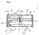
- the rotary ring 11 comprises two turntables 25, 26 which are mounted on the edge so that the area of their axis of rotation is free of mechanical fittings.
- the shooting lens 12A is arranged in the turntable 25 and the projection lens 12P, not shown here, is arranged in the turntable 26, both offset by the parallax angle 22.
- the motor drives 27, 28 for the turntables 25, 26, which are only indicated here, are program-controlled and take place either via a toothed belt system from the outside or by miniature stepper motors. Such drives are known to the person skilled in the art and need not be explained in more detail here.
- the multiplexer 23 comprises two deflection prisms / mirror arrangements, each of which is assigned to one of the turntables 25, 26.
- the arrangement assigned to the turntable 25 consists of two deflecting prisms or mirrors 29, 30, 30 mounted on the turntable 25 and a further deflecting prism or mirror, which is attached to a transparent support 32 rigidly arranged between the two turntables 25, 26.
- the arrangement associated with the turntable 26 consists of two deflection prisms or mirrors 33, 34 mounted on the turntable 26 and a further deflection prism or mirror 35 which is fastened on the transparent support 32.
- the deflection prisms or mirrors 31, 35 are arranged in the axis of rotation of the rotating ring 11 and are optically connected to the fiber cables 24A and 24P.
- the deflection prisms or mirrors 30, 34 are located in the axis of rotation of the rotary ring 11, whereby they are assigned to the deflection prisms or mirrors 31 and 35, respectively.
- the deflection prisms or mirrors 29, 33 are assigned to the objectives 12A and 12P.
- the device according to FIGS. 1, 4 and 5 works according to the triangulation and phase shift method. Both methods are known and are not explained in more detail here.
- the computer 7 digitally generates a certain, programmable stripe pattern, which is digitally stored in a projection image memory, not shown, and converted into a video signal for controlling the LCD matrix light modulator 5 in the video projector 2 via a digital / analog interface, also not shown.
- This LCD matrix light modulator 5 is irradiated with the light emitted by the incandescent lamp in order to modulate it point by point with high resolution and a large number of possible gray levels.
- the modulated light is projected via the imaging optics of the video projector 2, the optical fiber cable 24P, the deflecting prism / mirror arrangement 35, 34, 33 and the projection objective 12P onto the respectively set partial view of the tooth 15 to be measured in the form of a stripe pattern.
- the corresponding beam path is designated in FIG. 5 with the reference symbol 36.
- the recording lens 12A records the reflected or deformed light or stripe pattern, which is deformed in accordance with the topography of the respective partial view of the tooth 15 to be measured and is perceptible on the basis of the observation at the parallax angle 22, and conducts it along the beam path designated by reference number 37 in FIG. 5 the deflection prisms / mirror arrangement 29, 30, 31 and the optical fiber cable 24A of the CCD camera 6, which converts it into electrical data signals which are stored in the computer in For example, spherical coordinates, the origin of which is determined by the axis of rotation of the rotating ring 11 and is preferably inside or below the tooth, are converted and stored in a matrix memory.
- the above-described recording is repeated twice and the total measured values determined are evaluated in the computer. Subsequently, the two lenses 12A, 12P are successively transferred into the remaining five positions by correspondingly rotating the rotary ring 11 by the angular amount 14, in order to repeat the above-described recordings three times for each partial view.
- the data determined as a whole either serve to display an overall image comprising all of the partial views taken on a monitor and / or after correction by the dentist to control a grinding / milling device (not shown), for example in order to produce a tooth inlay or onlay.
- the oral probe 1 is preferably held in place by the patient's counterbite.
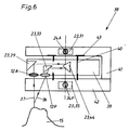
- FIG. 6 shows an oral probe 38 which differs from the oral probe 1 only in the construction details described below, but otherwise has the same function.
- the rotating ring 11 comprises a single turntable 39, which is rotatably supported by means of an axis of rotation 40 in a U-shaped arrangement 41 with a transparent leg 42 and can be driven by the drive 43.
- the objectives 12A, 12P and the associated deflecting prisms or mirrors 29 and 33 are fastened outside the axis of rotation.
- the oral probe 38 instead of the two deflecting prisms or mirrors 30, 34 according to the oral probe 1, the oral probe 38 only uses a single deflecting prism or mirror 44, which the deflecting prisms or which are also fixed in the axis of rotation, but stationary in the opposite legs of the U-shaped arrangement 41 mirrors 31, 35 are assigned.
- the mouth probe 45 shown in FIG. 7 differs from the mouth probes 1 and 38 in the construction features described below.
- the probe part 9 is designed as a non-rotatable ring 46, in which the lens arrangement used in the oral probe according to FIG. 4, consisting of the taking lens 12A and the projection lens 12P, is arranged in multiple, preferably six times, along a circular path. For reasons of space, however, only ten lenses are shown here.
- the distances between the individual lenses 12 are optionally adjustable.
- the acquisition lenses are without the interposition of a multiplexer 12A via an optical fiber cable 24A and all projection objectives 12P via an optical fiber cable 24P each connected to the CCD camera 6 or the video projector 2.
- This mouth probe 45 allows all partial views 16 to 21 to be illuminated simultaneously with the stripe pattern and to record the reflected stripe pattern.
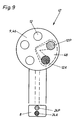
- the oral probe 47 shown in FIGS. 8 and 9 differs from the oral probe 45 in that, instead of five recording optics 12A and five associated projection optics 12P, it has only five, but preferably six or seven objectives 12, which are also at uniform intervals along a circular path are arranged on the non-rotatable ring 46.
- An optical multiplexer 48 which is only hinted at here and has basically the same structure as the prescribed multiplexer 23, connects two adjacent objectives 12 to the CCD camera 6 or the video projector 2 via the optical fiber cables 24A and 24P. In FIG. 8, the two serve the handle part 10 facing lenses as shooting lens 12A and projection lens 12P. After rotating counterclockwise by the amount of angle 14 into the position shown in FIG.
- the multiplexer 48 connects the lens used in the previous position for the projection, which is now used as the taking lens 12A, with the neighboring lens, which in this position as the projection lens 12P serves.
- the remaining lenses 12 are used in pairs to project the stripe pattern onto the remaining partial views and to record the reflected stripe patterns.
- no aids, such as calibration bodies, are required, since all partial views are recorded with great accuracy from precisely defined positions of the respective oral probe as well as the recording objectives 12A and projection objectives 12P and thus become one absolutely dimensioned 2D model can be computed computationally.
Landscapes
- Physics & Mathematics (AREA)
- Health & Medical Sciences (AREA)
- Engineering & Computer Science (AREA)
- General Physics & Mathematics (AREA)
- Veterinary Medicine (AREA)
- Electromagnetism (AREA)
- Life Sciences & Earth Sciences (AREA)
- Animal Behavior & Ethology (AREA)
- General Health & Medical Sciences (AREA)
- Public Health (AREA)
- Dentistry (AREA)
- Remote Sensing (AREA)
- Oral & Maxillofacial Surgery (AREA)
- Computer Networks & Wireless Communication (AREA)
- Epidemiology (AREA)
- Radar, Positioning & Navigation (AREA)
- Optics & Photonics (AREA)
- Dental Tools And Instruments Or Auxiliary Dental Instruments (AREA)
- Length Measuring Devices By Optical Means (AREA)
- Endoscopes (AREA)
Abstract
Description
Die Erfindung betrifft ein Verfahren und eine Vorrichtung zur dreidimensionalen optischen Vermessung von Oberflächen bzw. Körpern, insbesondere von Zähnen oder Zahngruppen in der Mundhöhle von Patienten, nach den Oberbegriffen der Patentansprüche 1 und 4 bis 6.The invention relates to a method and a device for three-dimensional optical measurement of surfaces or bodies, in particular teeth or groups of teeth in the oral cavity of patients, according to the preambles of
Aus der EP-A1 0278 882 ist eine derartige Vorrichtung bekannt, die mittels eines sog. Triangulationsverfahrens die Oberfläche von Zähnen zwecks Herstellung von Zahnprothesen vermißt. Bei dieser optischen dreidimensionalen Vermessung wird ein Streifenmuster auf den jeweils zu vermessenden Zahn projiziert und dieses ist dann unter einem Parallaxwinkel betrachtet. Aus den dabei beobachteten Verformungen des Streifenmusters läßt sich die Topographie des vermessenen Zahnes errechnen. Auch das sog. Cerec-System der Firma Siemens beschäftigt sich unter Verwendung des Triangulationsverfahrens mit der computergestützten Herstellung von Keramikinlays für Zähne. Die Vermessung eines Zahnes oder einer Zahngruppe erfolgt bei diesen bekannten Verfahren dadurch, daß der Zahnarzt die Sonde innerhalb der Mundhöhle des Patienten zeitlich nacheinander manuell in verschiedene Positionen relativ zum Zahn bringt, um einander überlappende Teilansichten des Zahnes aufzunehmen, die dann mittels des Rechners zu einem Gesamtbild zusammengesetzt werden. Aufgrund ihrer manuellen Handhabung durch den Zahnarzt befindet sich die Sonde während der Aufnahme der verschiedenen Teilansichten in unbestimmten Positionen, die nicht im definierten Verhältnis zueinander stehen. Infolgedessen können die einzelnen Teilansichten nur dann zu einem die Topographie des vermessenen Zahnes korrekt darstellenden Gesamtbild zusammengesetzt werden, wenn Kalibrationskörper in der Mundhöhle oder an den Zähnen des Patienten so befestigt werden, daß sie mit jeder Teilansicht mit vermessen werden können, um dem Rechner die korrekte Zuordnung der einzelnen Teilansichten zueinander zu ermöglichen.Such a device is known from EP-A1 0278 882, which measures the surface of teeth by means of a so-called triangulation method for the purpose of producing dental prostheses. In this optical three-dimensional measurement, a stripe pattern is projected onto the tooth to be measured and this is then viewed from a parallax angle. The topography of the measured tooth can be calculated from the deformations of the stripe pattern observed. The so-called Cerec system from Siemens also uses the triangulation process to deal with the computer-assisted production of ceramic inlays for teeth. In these known methods, a tooth or group of teeth is measured in that the dentist manually positions the probe within the patient's oral cavity one after the other in different positions relative to the tooth in order to record overlapping partial views of the tooth, which are then combined into one by means of the computer Overall picture. Due to its manual handling by the dentist, the probe is in indefinite positions during the acquisition of the various partial views, which are not in a defined relationship to each other. As a result, the individual partial views can only be put together to form an overall picture that correctly represents the topography of the measured tooth if calibration bodies are fastened in the oral cavity or on the teeth of the patient in such a way that they can be measured with each partial view in order for the computer to determine the correct one Allow the individual partial views to be assigned to one another.
Es ist Aufgabe der Erfindung, ein Verfahren und eine Vorrichtung der eingangs genannten Art so weiterzubilden, daß Vermessungen ohne Verwendung von Hilfsmitteln, wie beipsielsweise Kalibrierkörpern, einfacher, schneller und genauer durchgeführt werden können.It is an object of the invention to develop a method and a device of the type mentioned at the outset in such a way that measurements can be carried out more easily, quickly and precisely without the use of aids, such as calibration bodies.
Diese Aufgabe wird hinsichtlich des Verfahrens dadurch gelöst, daß die Beleuchtung der einzelnen Teilansichten und die Aufnahme der jeweils reflektierten Lichtmuster durchgeführt wird: entweder nacheinander mittels der wenigstens zwei Optiken, welche zu diesem Zweck innerhalb der Sonde aufeinanderfolgend in definierte, den einzelnen Teilansichten zugeordnete Positionen verschoben werden, oder gleichzeitig oder nacheinander mit mehr als zwei Optiken, die innerhalb der Sonde ortsfest in definierten, den einzelnen Teilansichten jeweils zugeordneten Positionen angebracht sind, wobei die Sonde in einer einzigen und damit bezüglich der gegenseitigen Zuordnung der einzelnen Teilansichten definierten Position gehalten wird.With regard to the method, this object is achieved in that the illumination of the individual partial views and the recording of the respectively reflected light patterns is carried out: either successively by means of the at least two optics, which for this purpose are successively shifted within the probe into defined positions assigned to the individual partial views be, or at the same time or in succession with more than two optics, which are fixed within the probe in fixed positions assigned to the individual partial views, the probe being held in a single position and thus defined with respect to the mutual association of the individual partial views.
Vorzugsweise wird nach dem Prinzip der Triangulation verfahren, wobei mittels jeweils einer Optik ein Streifenmuster auf die einzelnen Teilansichten projiziert und mittels einer anderen Optik das jeweils reflektierte, entsprechend der Topographie der jeweils vermessenen Teilansicht verformte Streifenmuster aufgenommen und als Grundlage zur Erzeugung der elektrischen Datensignale verwendet wird. Die Vorteile dieses Triangulationsverfahrens gegenüber dem interferometrischen Moiré-Verfahren besteht u.a. darin, daß kein kohärentes Licht erforderlich ist und keine Specklemuster auftreten.The principle of triangulation is preferably used, whereby a stripe pattern is projected onto the individual partial views by means of one lens and the stripe pattern reflected in each case, deformed in accordance with the topography of the measured partial view, is recorded and used as the basis for generating the electrical data signals . The advantages of this triangulation method compared to the interferometric moiré method include in that no coherent light is required and no speckle patterns occur.
Gemäß einer Weiterbildung des erfindungsgemäßen Verfahrens wird das Phasenshift-Prinzip angewendet, bei dem ein Streifenmuster mit einer durch eine Sinuskurve darstellbaren Helligkeitsverteilung mit jeweils verschiedener Phase wenigstens dreimal auf jede Teilansicht projiziert und das reflektierte Streifenmuster aufgenommen wird. Das die Gleichung jeder Sinuskurve drei Unbekannte, nämlich die Grundhelligkeit, den Helligkeitskontrast und die Phase der jeweiligen Wellenfront enthält, dienen die drei durchgeführten Aufnahmen zur Ermittlung der gesuchten Phase, wobei gleiche Phasen Punkte gleicher Höhe am vermessenen Körper darstellen. Der Vorteil gegenüber dem statische Streifenmuster projizierenden Verfahren liegt in der kontinuierlichen, flächenhaften Information im Gegensatz zu diskreten Konturlinien. Damit können Auflösungen erreicht werden, die im Bereich von wenigen Mikrometern liegen.According to a further development of the method according to the invention, the phase shift principle is used, in which a stripe pattern with a brightness distribution that can be represented by a sine curve, each with a different phase, is projected onto each partial view at least three times and the reflected stripe pattern is recorded. Since the equation of each sinusoid contains three unknowns, namely the basic brightness, the brightness contrast and the phase of the respective wavefront, the three recordings used serve to determine the phase sought, with the same phases representing points of the same height on the measured body. The advantage over the static strip pattern projecting method lies in the continuous, areal information in contrast to discrete contour lines. This enables resolutions to be achieved that are in the range of a few micrometers.
Zur Durchführung der Verfahrensvariante mit gleichzeitiger Beleuchtung der einzelnen Teilansichten und der Aufnahme der jeweils reflektierten Lichtmuster ist eine Vorrichtung vorgesehen, bei der dieZahl der jeweils zwei mit festgelegtem Abstand einander paarweise zugeordneten Optiken gleich der Anzahl der Teilansichten und ihre Anordnung innerhalb der Sonde ortsfest sowie gleich der gegenseitigen Anordnung der Teilansichten ist, wobei die eine der jeweils zwei einander paarweise zugeordneten Optiken an die Lichtquelle und die andere an den Bildsensor angeschlossen ist.In order to carry out the method variant with simultaneous illumination of the individual partial views and the recording of the respectively reflected light pattern, a device is provided in which the number of the two optics assigned to each other at a fixed distance is equal to the number of partial views and their arrangement within the probe is fixed and the same mutual arrangement of Is partial views, wherein one of the two optics assigned to each other in pairs is connected to the light source and the other to the image sensor.
Zur Durchführung der zweiten Verfahrensvariante mit aufeinanderfolgender Beleuchtung der einzelnen Teilansichten und der Aufnahme der jeweils reflektierten Lichtmuster ist eine Vorrichtung vorgesehen, bei der die Zahl der Optiken gleich der Anzahl der Teilansichten und ihre Anordnung innerhalb der Sonde ortsfest und gleich der gegenseitigen Anordnung der Teilansichten ist, wobei ein Multiplexer zum paarweisen gleichzeitigen Anschließen jeweils zweier Optiken an die Lichtquelle bzw. an den Bildsensor vorgesehen ist. Dabei können für diesen Anschluß entweder benachbarte oder nicht-benachtbart Optiken vorgesehen sein.In order to carry out the second method variant with successive illumination of the individual partial views and the recording of the respectively reflected light pattern, a device is provided in which the number of optics is equal to the number of partial views and their arrangement within the probe is fixed and the mutual arrangement of the partial views is the same, a multiplexer for pairwise simultaneous connection of two optics to the light source or to the image sensor is provided. Either adjacent or non-adjacent optics can be provided for this connection.
Die aufeinanderfolgende Beleuchtung der einzelnen Teilansichten und die Aufnahme der jeweils reflektierten Streifenmuster kann gemäß der dritten Verfahrensvariante mit einer Vorrichtung durchgeführt werden, bei der die wenigstens zwei mit festgelegtem Abstand einander paarweise zugeordneten Optiken in definierten, der Breite der Teilansichten entsprechenden Schritten innerhalb der Sonde entlang einer der gegenseitigen Anordnung der Teilansichten zugeordneten Bahn verschiebbar und über einen Multiplexer an die Lichtquelle bzw. an den Bildsensor anschließbar sind.The successive illumination of the individual partial views and the recording of the respectively reflected strip pattern can be carried out according to the third method variant with a device in which the at least two optics assigned to one another at a fixed distance in defined steps corresponding to the width of the partial views within the probe along a path the mutual arrangement of the partial views associated path can be moved and connected to the light source or to the image sensor via a multiplexer.
Vorzugsweise sind die Optiken entlang einer Kreisbahn oder einer Zylinderbahn angeordnet, bzw. verschiebbar.The optics are preferably arranged or displaceable along a circular path or a cylindrical path.
Zweckmäßigerweise sind die Lichtquelle und der Bildsensor außerhalb der Sonde angeordnet. Gemäß einer Weiterbildung der Erfindung ist zwischen der Lichtquelle und der Sonde ein LCD-Matrix-Lichtmodulator zum Erzeugen eines Streifenmusters zur Projektion auf die einzelnen Teilansichten angeordnet.The light source and the image sensor are expediently arranged outside the probe. According to a development of the invention, an LCD matrix light modulator is arranged between the light source and the probe for generating a stripe pattern for projection onto the individual partial views.
Günstig ist eine Anordnung der Lichtquelle in einem Videoprojektor.An arrangement of the light source in a video projector is favorable.
Vorzugsweise ist der Multiplexer ein optischer Muliplexor mit einer Prismen- und/oder Spiegelanordnung. Dabei kann der optische Multiplexer über optische Phaserkabel an die Lichtquelle bzw. den Bildsensor angeschlossen sein. Vorzugsweise ist der Bildsensor eine CCD-Kamera.The multiplexer is preferably an optical muliplexor with a prism and / or mirror arrangement. The optical multiplexer can be connected to the light source or the image sensor via optical phase cables. The image sensor is preferably a CCD camera.
Zur Vermessung von beispielsweise gegenüberstehenden Zähnen zwecks Anpassung ihrer beiden Kauflächen ist es zweckmäßig, wenn die Sonde zur Projektion des Lichtes in und zur Aufnahme der reflektierten Lichtmuster aus einander entgegengesetzten Richtungen ausgebildet ist.To measure opposing teeth, for example, in order to adapt their two occlusal surfaces, it is useful if the probe is used to project the light is formed in and for receiving the reflected light patterns from opposite directions.
Gemäß einer Weiterbildung der Erfindung umfaßt der Rechner Mittel zum Umrechnen der elektrischen Datensignale in Koordinaten. Dabei können die Koordinaten Kugelkoordinaten, beispielsweise für die Vermessung eines einzigen Zahnes, oder Zylinderkoordinaten, beispielsweise zur Vermessung von Zahngruppen, sein. Derartige Koodinaten gewährleisten, daß einander überlappende Meßflächen so gemittelt werden können, daß sie weitgehend absatzfrei ineinander übergehen. Auf diese Weise werden Mehrdeutigkeiten der Messungen ausgeschlossen. Dabei ist es günstig, wenn der Rechner einen Matrixspeicher zur Speicherung der Koordinaten umfaßt.According to a development of the invention, the computer comprises means for converting the electrical data signals into coordinates. The coordinates can be spherical coordinates, for example for the measurement of a single tooth, or cylindrical coordinates, for example for the measurement of groups of teeth. Such co-ordinates ensure that overlapping measuring surfaces can be averaged in such a way that they merge into one another largely without paragraphs. In this way, ambiguities in the measurements are excluded. It is advantageous if the computer comprises a matrix memory for storing the coordinates.
Zweckmäßigerweise ist die Lichtquelle eine Farblichtquelle oder wenigstens ein Farbfeld ist ihr nachgeschaltet. Wird beispielsweise ein Rotfilter oder Rotlicht verwendet, dann kann beispielsweise bei der Zahnvermessung eine deutliche Unterscheidung zwischen dem roten Zahnfleisch und dem weißen Zahn getroffen werden.The light source is expediently a color light source or at least one color field is connected downstream of it. If, for example, a red filter or red light is used, a clear distinction can be made, for example, between the red gums and the white teeth when measuring teeth.
Nachstehend ist die Erfindung anhand einiger Ausführungsbeispiele unter Bezugnahme auf die Zeichnung näher beschrieben. Es zeigen
Figur 1 eine schematische Darstellung eines zur Vermessung von Zähnen mittels einer Mundsonde vorgesehenen Ausführungsbeispiels der erfindungsgemäßen Vorrichtung,Figur 2 eine Draufsicht auf eine Gruppe von Zähnen,Figur 3 eine Seitenansicht der Zähne nachFigur 2,- Figur 4 eine Unteransicht der Mundsonde nach
Figur 1 als eine erste Variante, Figur 5 einen Querschnitt der Mundsonde nach Figur 4,Figur 6 einen Querschnitt einer zweiten Variante der Mundsonde, und- Figur 7 eine Unteransicht einer dritten Variante der Mundsonde, und
Figur 8 undFigur 9 je eine Unteransicht einer vierten Variante der Mundsonde.
- FIG. 1 shows a schematic illustration of an exemplary embodiment of the device according to the invention intended for measuring teeth by means of an oral probe,
- FIG. 2 shows a top view of a group of teeth,
- FIG. 3 shows a side view of the teeth according to FIG. 2,
- FIG. 4 shows a bottom view of the oral probe according to FIG. 1 as a first variant,
- FIG. 5 shows a cross section of the oral probe according to FIG. 4,
- Figure 6 shows a cross section of a second variant of the oral probe, and
- Figure 7 is a bottom view of a third variant of the oral probe, and
- 8 and 9 each show a bottom view of a fourth variant of the oral probe.
Die in Fig. 1 dargestellte Vorrichtung umfaßt eine in die Mundhöhle eines Patienten einführbare Mundsonde 1, einen Videoprojektor 2 mit einer Lichtquelle 3 in Form einer Glühlampe, einem Rotfilter 4 und einem LCD-Matrix-Lichtmodulator 5, die beide im Strahlengang des Projektors angeordnet sind, einen Bildsensor 6 in Form einer CCD-Kamera, einen Rechner 7 und eine optische Faserkabelverbindung 8 zwischen der Mundsonde 1 und dem Videoprojektor 2 sowie der CCD-Kamera 6.The device shown in FIG. 1 comprises an
Die in Fig. 4 vergrößert dargestellte Mundsonde 1 besteht aus einem Sondenteil 9 und einem Handgriffteil 10. Der Sondenteil 9 umfaßt einen mittels eines nicht gezeigten programmgesteuerten Drehantriebs schrittweise drehbaren Drehring 11, in welchem zwei gleichartig ausgebildete Mikrooptiken in Form je eines Objektivs 12 mit festgelegtem, jedoch verstellbarem Winkelabstand 13 angeordnet sind. Eines der Objektive dient als Aufnahmeobjektiv 12A und das andere Projektionsobjektiv 12P. Der Drehring 11 ist um jeweils einen definierten Winkelbetrag 14 in vorzugsweise sechs definierte Positionen schrittweise drehbar. Sechs Positionen sind deshalb gewählt, weil es zur vollständigen dreidimensionalen Vermessung eines Zahnes 15 vorteilhaft ist, sechs Teilansichten 16-21 von schräg oben aufzunehmen, wie dies in den Fig. 2 und 3 gezeigt ist. Der Winkelbetrag 14 und damit die jeweils aufzunehmenden Teilansichten können mittels der Programmsteuerung beliebig verändert werden. Ebenfalls verändert werden kann der Winkelabstand 13 zur Verstellung des Parallaxwinkels 22 zwischen dem Projektionsobjektiv 12P und dem Aufnahmeobjektiv 12A. Ein optischer Multiplexer 23 im Sondenteil 9 dient zur optischen Kupplung beider Objektive 12A, 12P mit je einem optischen Faserkabel 24A bzw. 24P, die den Handgriffteil 10 und die sich anschließende Faserkabelverbindung 8 durchlaufen. Das Faserkabel 24P verbindet über den Multiplexer 23 das Projektionsobjektiv 12P mit dem Videoprojektor 2, während das Faserkabel 24A ebenfalls über den Multiplexer 23 den Anschluß des Aufnahmeobjektivs 12A an die CCD-Kamera 6 herstellt.The
Gemäß Fig. 5 umfaßt der Drehring 11 zwei Drehteller 25, 26, die randseitig gelagert sind, so daß der Bereich ihrer Drehachse frei von mechanischen Einbauten ist. Im Drehteller 25 ist das Aufnahmeobjektiv 12A und im Drehteller 26 das hier nicht gezeigte Projektionsobjektiv 12P, beide um dem Parallaxwinkel 22 versetzt, angeordnet. Die hier lediglich angedeuteten motorischen Antriebe 27,28 für die Drehteller 25,26 sind programmgesteuert und erfolgen entweder über ein Zahnriemensystem von außen oder durch Miniatur-Schrittmotoren. Solche Antriebe sind dem Fachmann bekannt und brauchen hier nicht näher erläutert zu werden.5, the
Der Multiplexer 23 umfaßt zwei Umlenkprismen/Spiegelanordnungen, die je einem der Drehteller 25,26 zugeordnet sind. Die dem Drehteller 25 zugeordnete Anordnung besteht aus zwei auf dem Drehteller 25 montierten Umlenkprismen oder -spiegeln, 29,30 und einem weiteren Umlenkprisma oder -spiegel, das auf einem starr zwischen beiden Drehtellern 25,26 angeordneten durchsichtigen Träger 32 befestigt ist. Die dem Drehteller 26 zugeordnete Anordnung besteht aus zwei am Drehteller 26 montierten Umlenkprismen oder -spiegeln 33,34 und einem weiteren Umlenkprisma oder -spiegel 35, das auf dem durchsichtigen Träger 32 befestigt ist. Die Umlenkprismen oder - spiegel 31,35 sind in der Drehachse des Drehrings 11 angeordnet und optisch mit den Faserkabeln 24A bzw. 24P verbunden. Die Umlenkprismen oder -spiegel 30,34 befinden sich in der Drehachse des Drehringes 11, wobei sie den Umlenkprismen oder - spiegeln 31 bzw. 35 zugeordnet sind. Die Umlenkprismen oder -spiegel 29,33 sind den Objektiven 12A bzw. 12P zugeordnet.The
Die Vorrichtung gemäß den Fig. 1,4 und 5 arbeitet nach dem Triangulations- und Phasenshiftverfahren. Beide Verfahren sind bekannt und werden hier nicht näher erläutert.The device according to FIGS. 1, 4 and 5 works according to the triangulation and phase shift method. Both methods are known and are not explained in more detail here.
Der Rechner 7 erzeugt digital ein bestimmtes, programmierbares Streifenmuster, das in einem nicht gezeigten Projektionsbildspeicher digital gespeichert und über eine ebenfalls nicht gezeigte Digital/Analog-Schnittstelle in ein Videosignal zur Ansteuerung des LCD-Matrix-Lichtmodulators 5 im Videoprojektor 2 umgewandelt wird. Dieser LCD-Matrix-Lichtmodulator 5 wird mit dem von der Glühlampe ausgestrahlten Licht durchstrahlt, um dieses punktweise mit hoher Auflösung und einer großen Anzahl von möglichen Graustufen zu modulieren. Das modulierte Licht wird über die Abbildungsoptik des Videoprojektors 2, das optische Faserkabel 24P, die Umlenkprisma/Spiegelanordnung 35,34,33 und das Projektionsobjektiv 12P auf die jeweils eingestellte Teilansicht des zu vermessenden Zahnes 15 in Form eines Streifenmusters projiziert. Der entsprechende Strahlengang ist in Fig. 5 mit dem Bezugszeichen 36 bezeichnet. Das Aufnahmeobjektiv 12A nimmt das reflektierte und entsprechend der Topographie der jeweiligen Teilansicht des zu vermessenden Zahnes 15 verformte und aufgrund der Beobachtung unter dem Parallaxwinkel 22 wahrnehmbare Licht- oder Streifenmuster auf und leitet es entlang dem in der Fig. 5 mit dem Bezugszeichen 37 bezeichneten Strahlengang über die Umlenkprismen/Spiegelanordnung 29,30,31 und das optische Faserkabel 24A der CCD-Kamera 6 zu, die es in elektrische Datensignale umwandelt, die im Rechner in beispielsweise Kugelkoordinaten, deren Ursprung durch die Drehachse des Drehrings 11 bestimmt wird und vorzugsweise im Inneren des Zahnes oder unterhalb desselben liegt, umgerechnet und in einem Matrixspeicher abgelegt werden. Gemäß dem bereits beschriebenen Phasenshiftverfahren wird die vorbeschriebene Aufnahme zweimal wiederholt und die insgesamt ermittelten Meßwerte im Rechner ausgewertet. Anschließend werden die beiden Objektive 12A, 12P durch entsprechende Drehung des Drehrings 11 um den Winkelbetrag 14 nacheinander in die verbleibenden fünf Positionen überführt, um die vorbeschriebenen Aufnahmen für jede Teilansicht jeweils dreimal zu wiederholen. Die insgesamt ermittelten Daten dienen entweder zur Darstellung eines sämtliche aufgenommenen Teilansichten umfassenden Gesamtbildes auf einem Monitor und/oder nach evtl. Korrektur durch den Zahnarzt zur Steuerung einer nicht gezeigten Schleif/Fräseinrichtung, um beispielsweise ein Zahninlay oder -onlay herzustellen. Obwohl die gesamten Aufnahmen nur einen sehr kurzen Zeitraum erfordern, wird die Mundsonde 1 vorzugsweise währenddessen durch den Gegenbiß des Patienten an Ort und Stelle gehalten.The computer 7 digitally generates a certain, programmable stripe pattern, which is digitally stored in a projection image memory, not shown, and converted into a video signal for controlling the LCD
Fig. 6 zeigt eine Mundsonde 38, die sich von der Mundsonde 1 lediglich durch die nachstehend beschriebenen Konstruktionsdetails unterscheidet, im übrigen jedoch die gleiche Funktion aufweist. Der Drehring 11 umfaßt einen einzigen Drehteller 39, der mittels einer Drehachse 40 in einer U-förmigen Anordnung 41 mit einem durchsichtigen Schenkel 42 drehbar gelagert und mittels des Antriebs 43 antreibbar ist. Auf der dem durchsichtigen Schenkel 42 zugewandten Seite des Drehtellers 39 sind außerhalb der Drehachse die Objektive 12A, 12P und die zugeordneten Umlenkprismen oder -spiegel 29 bzw. 33 befestigt. Statt der zwei Umlenkprismen oder -spiegeln 30, 34 gemäß der Mundsonde 1 verwendet die Mundsonde 38 lediglich ein einziges Umlenkprisma oder -spiegel 44, welchem die ebenfalls in der Drehachse, jedoch stationär in den einander gegenüberliegenden Schenkeln der U-förmigen Anordnung 41 befestigten Umlenkprismen oder -spiegel 31,35 zugeordnet sind.FIG. 6 shows an
Die in Fig. 7 gezeigte Mundsonde 45 unterscheidet sich von den Mundsonden 1 und 38 durch die nachstehend beschriebenen Konstruktionsmerkmale. Der Sondenteil 9 ist als nicht drehbarer Ring 46 ausgebildet, in welchem die in der Mundsonde nach Fig. 4 verwendete Objektivanordnung bestehend aus dem Aufnahmeobjektiv 12A und dem Projektionsobjektiv 12P in mehrfacher, vorzugsweise sechsfacher Ausfertigung entlang einer Kreisbahn angeordnet ist. Aus Platzgründen sind hier jedoch nur zehn Objektive eingezeichnet. Die Abstände zwischen den einzelnen Objektiven 12 sind wahlweise verstellbar. Ohne Zwischenschaltung eines Multiplexers sind die Aufnahmeobjektive 12A über je ein optisches Faserkabel 24A und sämtliche Projektionsobjektive 12P über je ein optisches Faserkabel 24P an die CCD-Kamera 6 bzw. den Videoprojektor 2 angeschlossen. Diese Mundsonde 45 erlaubt es, sämtliche Teilansichten 16 bis 21 gleichzeitig mit dem Streifenmuster zu beleuchten und das reflektierte Streifenmuster aufzunehmen.The
Die in den Fig. 8 und 9 gezeigte Mundsonde 47 unterscheidet sich von der Mundsonde 45 dadurch, daß sie statt fünf Aufnahmeoptiken 12A und fünf zugeordneten Projektionsoptiken 12P lediglich fünf, vorzugsweise jedoch sechs oder sieben Objektive 12 aufweist, die ebenfalls mit gleichmäßigen Abständen entlang einer Kreisbahn auf dem nicht drehbaren Ring 46 angeordnet sind. Ein hier lediglich angedeuteter optischer Multiplexer 48 von prinzipiell gleichem Aufbau wie der vorgeschriebene Multiplexer 23 verbindet jeweils zwei benachbarte Objektive 12 über die optischen Faserkabel 24A und 24P mit der CCD-Kamera 6 bzw. dem Videoprojektor 2. In Fig. 8 dienen die zwei dem Handgriffteil 10 zugewandten Objektive als Aufnahmeobjektiv 12A und Projektionsobjektiv 12P. Nach Drehung um den Winkelbetrag 14 entgegen dem Uhrzeigersinn in die in Fig. 9 gezeigte Stellung verbindet der Multiplexer 48 das in der vorhergehenden Stellung zur Projektion dienende Objektiv, das nun als Aufnahmeobjektiv 12A eingesetzt wird, mit dem benachbarten Objektiv, das in dieser Stellung als Projektionsobjektiv 12P dient. Durch weitere schrittweise Drehung jeweils um den Winkelbetrag 14 werden die verbleibenden Objektive 12 jeweils paarweise zur Projektion des Streifenmusters auf die verbleibenden Teilansichten und zur Aufnahme der reflektierten Streifenmuster verwendet. Dabei sind ebenso wie bei dem Einsatz der vorbeschriebenen Mundsonden 1, 38 und 45 keinerlei Hilfsmittel, wie etwa Kalibrationskörper, erforderlich, da sämtliche Teilansichten mit großer Genauigkeit aus exakt definierten Positionen der jeweiligen Mundsonde sowie der Aufnahmeobjektive 12A und Projektionsobjektive 12P aufgenommen werden und somit zu einem absolut vermaßten 2D-Modell rechnerisch zusammengesetzt werden können.The
Claims (19)
- Process for the three-dimensional optical measurement of surfaces or bodies, in particular of teeth or tooth groups in the oral cavity of patients, with all the partial views of the body to be measured being illuminated with light emitted from a light source, in particular in the form of a striated pattern, with the aid of at least two optical systems associated with one another at a fixed distance in a probe, and the light patterns reflected from the partial views being imaged at a parallax angle corresponding to the distance between the two optical systems and being supplied to an image sensor which converts the light patterns into electrical data signals which are evaluated in a computer for the provision of a total image encompassing all the partial views and representing the measured body,
characterized in that
the illumination of the individual partial views and the imaging of the respectively reflected light patterns is carried out: either one after the other by means of the at least two optical systems, which for this purpose are displaced within the probe successively into defined positions associated with the individual partial views, or at the same time or after one another with more than two optical systems which are fitted within the probe in a fixed manner in defined positions respectively associated with the individual partial views, with the probe being held in a single position which is therefore defined with respect to the mutual association of the individual partial views. - Process according to claim 1,
characterized in that
the principle of triangulation is applied, in which by means of at least the one optical system a striated pattern is projected on to the individual partial views and by means of at least the other optical system the respectively reflected striated pattern formed corresponding to the topography of the respectively measured partial view is imaged and is used as the basis for generating the electrical data signals. - Process according to claim 1 or 2,
characterized in that
the phase shift principle is applied, where a striated pattern with a brightness distribution which can be represented by a sine curve with in each case displaced phase is projected at least three times on to each partial view and the reflected striated pattern is imaged. - Device for carrying out the process according to at least one of claims 1-3, having at least one light source (3) for emitting light, a probe (1) with at least two optical systems (12A, 12P), associated with one another at a fixed distance, for illuminating all the partial views of the body to be measured with the light, in particular in the form of a striated pattern, and for imaging the light patterns reflected from the partial views at a parallax angle corresponding to the distance between the optical systems, an image sensor (6) for converting the reflected light patterns into electrical data signals and a computer (7) for evaluating the electrical data signals for the purpose of providing a total image encompassing all the partial views and representing the measuring body,
characterized in that
the number of paired optical systems (12A, 12P), in each case with two optical systems associated with one another at a fixed distance, equals the number of partial views (16-21) and their arrangement within the probe (45) is fixed and is the same as the opposite arrangement of the partial views (16-21), and in that in each case one (12P) of the paired optical systems is connected to the light source (3) and the other one (12A) to the image sensor (6) (Figure 7). - Device for carrying out the process according to at least one of claims 1-3, having at least one light source (3) for emitting light, a probe (1) with at least two optical systems (12P, 12A), associated with one another at a fixed distance, for illuminating all the partial views of the body to be measured with the light, in particular in the form of a striated pattern, and for imaging the light patterns reflected from the partial views at a parallax angle corresponding to the distance between the optical systems, an image sensor (6) for converting the reflected light patterns into electrical data signals and a computer (7) for evaluating the electrical data signals for the purpose of providing a total image encompassing all the partial views and representing the measuring body,
characterized in that
the number of optical systems (12P, 12A) equals the number of partial views (16-21) and their arrangement within the probe (47) is fixed and equals the opposite arrangement of the partial views (16-21), and in that a multiplexer (48) is provided for the paired simultaneous connection of each two optical systems (12P, 12A) to the light source (3) and to the image sensor (6) (Figures 8 and 9). - Device for carrying out the process according to at least one of claims 1-3, having at least one light source (3) for emitting light, a probe (1) with at least two optical systems (12P, 12A), associated with one another at a fixed distance, for illuminating all the partial views of the body to be measured with the light, in particular in the form of a striated pattern, and for imaging the light patterns reflected from the partial views at a parallax angle corresponding to the distance between the optical systems, an image sensor (6) for converting the reflected light patterns into electrical data signals and a computer (7) for evaluating the electrical data signals for the purpose of providing a total image encompassing all the partial views and representing the measuring body,
characterized in that
the at least two optical systems (12A, 12P) in paired association with one another at a fixed distance can be displaced in defined steps corresponding to the width of the partial views (16-21) within the probe (1) along a path associated with the opposite arrangement of the partial views (16-21) and can be connected by way of a multiplexer (23) to the light source (3) and to the image sensor (6) (Figures 1, 4-6). - Device according to at least one of claims 4, 5 and 6,
characterized in that
the optical systems (12; 12A, 12P) are arranged and are displaceable along a circular path or cylindrical path. - Device according to at least one of claims 4 to 7,
characterized in that
the light source (3) and the image sensor (6) are arranged outside the probe (1, 38, 45, 47). - Device according to at least one of claims 4 to 8,
characterized in that
a LCD matrix light modulator (5) for generating a striated pattern for projection on to the individual partial views (16-21) is arranged between the light source (3) and the probe (1, 38, 45, 47). - Device according to claim 8 or 9,
characterized in that
the light source (3) is arranged in a video projector (2). - Device according to at least one of claims 4 to 10,
characterized in that
the multiplexer (23, 48) is an optical multiplexer with a deviating prism arrangement and/or mirror arrangement (29-31, 33-35, 44). - Device according to claim 11,
characterized in that
the optical multiplexer (23, 48) is connected by way of optical fibre cables (24A, 24P) to the light source (3) and the image sensor (6). - Device according to at least one of claims 4 to 12,
characterized in that
the image sensor (6) is a CCD camera. - Device according to at least one of claims 4 to 13,
characterized in that
the probe is constructed for projecting the light in and for imaging the reflected striated patterns from opposite directions. - Device according to at least one of claims 4 to 14,
characterized in that
the computer (7) comprises means for converting the electrical data signals into coordinates. - Device according to claim 15,
characterized in that
the coordinates are spherical coordinates. - Device according to claim 15,
characterized in that
the coordinates are cylindrical coordinates. - Device according to at least one of claims 15 to 17,
characterized in that
the computer (7) comprises a matrix memory for storing the coordinates. - Device according to at least one of claims 4 to 18,
characterized in that
the light source (3) is a colour-light source or in that at least one colour filter (4) is connected downstream.
Applications Claiming Priority (3)
| Application Number | Priority Date | Filing Date | Title |
|---|---|---|---|
| DE3933994A DE3933994A1 (en) | 1989-10-11 | 1989-10-11 | OPTICAL PROBE FOR ABSOLUTE 3-DIMENSIONAL MEASUREMENT OF INDIVIDUAL TEETH AND GROUPS OF TEETH IN THE ORAL CAVE |
| DE3933994 | 1989-10-11 | ||
| PCT/EP1990/001715 WO1991005520A1 (en) | 1989-10-11 | 1990-10-11 | Process and device for the three-dimensional optical measurement, especially of teeth in patients' buccal cavities |
Publications (2)
| Publication Number | Publication Date |
|---|---|
| EP0447531A1 EP0447531A1 (en) | 1991-09-25 |
| EP0447531B1 true EP0447531B1 (en) | 1994-04-20 |
Family
ID=6391289
Family Applications (1)
| Application Number | Title | Priority Date | Filing Date |
|---|---|---|---|
| EP90915117A Expired - Lifetime EP0447531B1 (en) | 1989-10-11 | 1990-10-11 | Process and device for the three-dimensional optical measurement, especially of teeth in patients' buccal cavities |
Country Status (4)
| Country | Link |
|---|---|
| EP (1) | EP0447531B1 (en) |
| JP (1) | JPH04504219A (en) |
| DE (1) | DE3933994A1 (en) |
| WO (1) | WO1991005520A1 (en) |
Families Citing this family (16)
| Publication number | Priority date | Publication date | Assignee | Title |
|---|---|---|---|---|
| DE4206836C2 (en) * | 1992-03-04 | 1994-07-14 | Kaltenbach & Voigt | Probe for the optical measurement of teeth |
| DE4213909A1 (en) * | 1992-04-28 | 1993-11-04 | Mtu Muenchen Gmbh | DEVICE FOR MEASURING EDGE PROFILES FROM EDGES |
| DE4218219C2 (en) * | 1992-06-03 | 1998-05-07 | Geyer Medizin Und Fertigungste | Device for the contactless measurement of a difficult to access, three-dimensional medical or dental object |
| DE4229466C2 (en) * | 1992-09-03 | 2001-04-26 | Kaltenbach & Voigt | Tooth measurement without calibration body |
| JPH06137841A (en) * | 1992-10-29 | 1994-05-20 | Nikon Corp | Ophthalmological measuring device |
| NL9301308A (en) | 1993-07-26 | 1995-02-16 | Willem Frederick Van Nifterick | Method of securing a dental prosthesis to implants in a patient's jawbone and using means thereof. |
| DE4325542A1 (en) * | 1993-07-29 | 1995-02-02 | Fraunhofer Ges Forschung | Method for three-dimensional measurement of inaccessible cavities |
| DE19536297C2 (en) * | 1995-09-29 | 2003-10-02 | Daimler Chrysler Ag | Method for the geometric calibration of 3D optical sensors for the three-dimensional measurement of objects and apparatus for this purpose |
| US6648640B2 (en) | 1999-11-30 | 2003-11-18 | Ora Metrix, Inc. | Interactive orthodontic care system based on intra-oral scanning of teeth |
| US7027642B2 (en) | 2000-04-28 | 2006-04-11 | Orametrix, Inc. | Methods for registration of three-dimensional frames to create three-dimensional virtual models of objects |
| ITCS20040012A1 (en) * | 2004-08-09 | 2004-11-09 | Calabrian High Tech Srl | New Technology for one-step Implant Prosthetics |
| DE102007054907A1 (en) * | 2007-11-15 | 2009-05-28 | Sirona Dental Systems Gmbh | Method for the optical measurement of objects using a triangulation method |
| DE102008054985B4 (en) | 2008-12-19 | 2012-02-02 | Sirona Dental Systems Gmbh | Method and device for optical measurement of three-dimensional objects by means of a dental 3D camera using a triangulation method |
| DE102012021185A1 (en) | 2012-10-30 | 2014-04-30 | Smart Optics Sensortechnik Gmbh | Method for 3D optical measurement of teeth with reduced point-spread function |
| DE102020008179B4 (en) | 2020-10-22 | 2023-10-26 | Smart Optics Sensortechnik Gmbh | Method and device for optical three-dimensional measurement of objects |
| DE102020127894B4 (en) | 2020-10-22 | 2022-09-22 | Smart Optics Sensortechnik Gmbh | Method and device for the optical three-dimensional measurement of objects |
Family Cites Families (3)
| Publication number | Priority date | Publication date | Assignee | Title |
|---|---|---|---|---|
| FR2610821B1 (en) * | 1987-02-13 | 1989-06-09 | Hennson Int | METHOD FOR TAKING MEDICAL IMPRESSION AND DEVICE FOR IMPLEMENTING SAME |
| GB8719951D0 (en) * | 1987-08-24 | 1987-09-30 | Lbp Partnership | Three-dimensional scanner |
| ATE76502T1 (en) * | 1988-10-18 | 1992-06-15 | Hasenclever Maschf Sms | METHOD AND DEVICE FOR DETERMINING THE GEOMETRY OF A BODY. |
-
1989
- 1989-10-11 DE DE3933994A patent/DE3933994A1/en not_active Withdrawn
-
1990
- 1990-10-11 EP EP90915117A patent/EP0447531B1/en not_active Expired - Lifetime
- 1990-10-11 JP JP2514123A patent/JPH04504219A/en active Pending
- 1990-10-11 WO PCT/EP1990/001715 patent/WO1991005520A1/en active IP Right Grant
Also Published As
| Publication number | Publication date |
|---|---|
| JPH04504219A (en) | 1992-07-30 |
| EP0447531A1 (en) | 1991-09-25 |
| WO1991005520A1 (en) | 1991-05-02 |
| DE3933994A1 (en) | 1991-05-08 |
Similar Documents
| Publication | Publication Date | Title |
|---|---|---|
| EP0447531B1 (en) | Process and device for the three-dimensional optical measurement, especially of teeth in patients' buccal cavities | |
| DE4218219C2 (en) | Device for the contactless measurement of a difficult to access, three-dimensional medical or dental object | |
| EP0299490B2 (en) | Method for producing dental prosthesis | |
| EP0923704B1 (en) | Optical imaging method and device | |
| EP2079981B1 (en) | Device and method for the contactless detection of a three-dimensional contour | |
| EP3154469B1 (en) | Measuring apparatus and method for three-dimensional measurement of an oral cavity | |
| DE10344922B4 (en) | All-scanner | |
| DE3829925A1 (en) | Optical probe for 3D measurement of teeth in the buccal cavity | |
| DE102011077564B4 (en) | Method for the optical three-dimensional measurement of a dental object | |
| DE602005004332T2 (en) | Method for providing data related to the oral cavity | |
| EP1805480B1 (en) | Method and device for detecting the contour data and/or optical characteristics of a three-dimensional semi-transparent object | |
| EP1757902B1 (en) | Method and apparatus for measuring the shape of a dental object | |
| DE4229466C2 (en) | Tooth measurement without calibration body | |
| WO1991013586A1 (en) | Process and device for measuring the dimensions of a space, in particular a buccal cavity | |
| EP1406555B1 (en) | Method and device for the there-dimensional determination and digitisation of a dental model | |
| EP1105067A1 (en) | Method for the computer-controlled production of dentures | |
| EP2846729B1 (en) | Method for measuring a dental situation | |
| DE3810455A1 (en) | Method and device for the contactless, three-dimensional measurement of an irregular body | |
| DE4206836C2 (en) | Probe for the optical measurement of teeth | |
| DE102011123028B3 (en) | Method for the optical three-dimensional measurement of a dental object | |
| DE4130238A1 (en) | Measuring vol., esp. interior of mouth with upper and lower dentures - projecting light into mouth via deflection device also used to deflect reflected light to evaluation device. | |
| DE102011123029B3 (en) | Method for the optical three-dimensional measurement of a dental object | |
| DE102012205800A1 (en) | Device for combining surface model and volume model of objects e.g. human skull during orthodontic treatment, has model registrant that is provided to align models relative to each other, such that coverage measurement is maximized | |
| DE10307209A1 (en) | Dental method for creating dimensional data for dental prostheses, whereby two or more pattern projection data sets relating to an object are combined using data set linking means for implying a movement between projection points |
Legal Events
| Date | Code | Title | Description |
|---|---|---|---|
| PUAI | Public reference made under article 153(3) epc to a published international application that has entered the european phase |
Free format text: ORIGINAL CODE: 0009012 |
|
| AK | Designated contracting states |
Kind code of ref document: A1 Designated state(s): CH FR IT LI |
|
| 17P | Request for examination filed |
Effective date: 19910724 |
|
| 17Q | First examination report despatched |
Effective date: 19930617 |
|
| GRAA | (expected) grant |
Free format text: ORIGINAL CODE: 0009210 |
|
| AK | Designated contracting states |
Kind code of ref document: B1 Designated state(s): CH FR IT LI |
|
| ITF | It: translation for a ep patent filed |
Owner name: JACOBACCI CASETTA & PERANI S.P.A. |
|
| ET | Fr: translation filed | ||
| PGFP | Annual fee paid to national office [announced via postgrant information from national office to epo] |
Ref country code: FR Payment date: 19941017 Year of fee payment: 5 |
|
| PGFP | Annual fee paid to national office [announced via postgrant information from national office to epo] |
Ref country code: CH Payment date: 19941121 Year of fee payment: 5 |
|
| PLBE | No opposition filed within time limit |
Free format text: ORIGINAL CODE: 0009261 |
|
| STAA | Information on the status of an ep patent application or granted ep patent |
Free format text: STATUS: NO OPPOSITION FILED WITHIN TIME LIMIT |
|
| 26N | No opposition filed | ||
| PG25 | Lapsed in a contracting state [announced via postgrant information from national office to epo] |
Ref country code: LI Effective date: 19951031 Ref country code: CH Effective date: 19951031 |
|
| REG | Reference to a national code |
Ref country code: CH Ref legal event code: PL |
|
| PG25 | Lapsed in a contracting state [announced via postgrant information from national office to epo] |
Ref country code: FR Effective date: 19960628 |
|
| REG | Reference to a national code |
Ref country code: FR Ref legal event code: ST |
|
| PG25 | Lapsed in a contracting state [announced via postgrant information from national office to epo] |
Ref country code: IT Free format text: LAPSE BECAUSE OF NON-PAYMENT OF DUE FEES;WARNING: LAPSES OF ITALIAN PATENTS WITH EFFECTIVE DATE BEFORE 2007 MAY HAVE OCCURRED AT ANY TIME BEFORE 2007. THE CORRECT EFFECTIVE DATE MAY BE DIFFERENT FROM THE ONE RECORDED. Effective date: 20051011 |