EP0446103A2 - Apparatus for picking up grass, dead leaves and the like - Google Patents
Apparatus for picking up grass, dead leaves and the like Download PDFInfo
- Publication number
- EP0446103A2 EP0446103A2 EP91400540A EP91400540A EP0446103A2 EP 0446103 A2 EP0446103 A2 EP 0446103A2 EP 91400540 A EP91400540 A EP 91400540A EP 91400540 A EP91400540 A EP 91400540A EP 0446103 A2 EP0446103 A2 EP 0446103A2
- Authority
- EP
- European Patent Office
- Prior art keywords
- tank
- mower
- axis
- trunk
- lawn
- Prior art date
- Legal status (The legal status is an assumption and is not a legal conclusion. Google has not performed a legal analysis and makes no representation as to the accuracy of the status listed.)
- Withdrawn
Links
Images


Classifications
-
- A—HUMAN NECESSITIES
- A01—AGRICULTURE; FORESTRY; ANIMAL HUSBANDRY; HUNTING; TRAPPING; FISHING
- A01D—HARVESTING; MOWING
- A01D43/00—Mowers combined with apparatus performing additional operations while mowing
- A01D43/06—Mowers combined with apparatus performing additional operations while mowing with means for collecting, gathering or loading mown material
- A01D43/077—Mowers combined with apparatus performing additional operations while mowing with means for collecting, gathering or loading mown material with auxiliary means, e.g. fans, for transporting the mown crop
-
- A—HUMAN NECESSITIES
- A01—AGRICULTURE; FORESTRY; ANIMAL HUSBANDRY; HUNTING; TRAPPING; FISHING
- A01D—HARVESTING; MOWING
- A01D2101/00—Lawn-mowers
-
- A—HUMAN NECESSITIES
- A01—AGRICULTURE; FORESTRY; ANIMAL HUSBANDRY; HUNTING; TRAPPING; FISHING
- A01D—HARVESTING; MOWING
- A01D34/00—Mowers; Mowing apparatus of harvesters
- A01D34/01—Mowers; Mowing apparatus of harvesters characterised by features relating to the type of cutting apparatus
- A01D34/412—Mowers; Mowing apparatus of harvesters characterised by features relating to the type of cutting apparatus having rotating cutters
- A01D34/63—Mowers; Mowing apparatus of harvesters characterised by features relating to the type of cutting apparatus having rotating cutters having cutters rotating about a vertical axis
Definitions
- the present invention relates to an apparatus for collecting grass, dead leaves and other soil from the soil.
- the device can be worn on a maintenance vehicle, on a tractor, it can be towed or even self-propelled.
- the supply duct In known devices, the supply duct, generally made of plastic, is relatively rigid. Unfortunately, this system allows only a small and insufficient displacement of the collector relative to the fan.
- the subject of the present invention is the use of a suction duct provided with at least one flexible sleeve. In a preferred form, this conduit is composed of a rigid wire forming a framework wound in the helical shape and embedded in a simple plastic envelope.
- the application of this ventilator technique relates to any device for collecting grass, dead leaves and other soil stains within the scope of the present invention.
- this or these springs will advantageously be replaced by an articulated tie rod for controlling the position of the hatch.
- This tiran is connected, on the one hand by means of an axis at one of its ends, to an arm secured to one of the support arms of the hatch, and on the other hand to the other end , rigidly to a door position lever.
- This tiran in the vicinity of its articulation will rest on a fixed stop judiciously positioned so as to prevent the closing of its articulation under the untimely action of the hatch and thus so as to prevent the accidental opening of the latter.
- the walls of the tank where the picked up product is stored are partially made of perforated sheets, or other systems of the same kind, so as to ensure the evacuation of the air rejected by the fan and carrying the picked up product. .
- this technique has the undesirable consequence of creating a cloud of dust all around the device.
- the object of the present invention is to avoid this cloud by using a tank with solid walls and by providing inside the tank, or communicating with the inside of the tank, a system for separating the air and the transported material. , it can be for example a cyclone.
- a baffle system separating the air from the solid particles it contains is preferably used. The outlet of this system will open to the air.
- An improvement to this improvement consists in connecting this outlet orifice to the air inlet in the collector of the product to be picked up by an adequate pipe.
- the air conveyed from the collection point to the tank partially circulates in a closed circuit serving as a carrier for the product to be picked up.
- these baffles will have the appearance of a drawer in the upper part of the tank and housed in a special compartment. By pulling this drawer we get rid of these baffles of the dust they retain.
- the opening in this compartment for the entry of air into these baffles is naturally inside the tank, while the exit opening to the outside can be connected by a suitable hose to the air inlet on the suction side.
- the air penetration orifice in these baffles is in an approximately horizontal plane. And the fact of extracting the drawer towards the outside makes it possible to successively rid all the baffles of the solid bodies accumulated by fall by gravity inside the very tank. This device allows the cleaning, if necessary, of the baffles during work without polluting the surface of the collection.
- the rotation for the discharge of the tank is naturally around an axis located in the vicinity of the upper edge on the side of the tank corresponding to the discharge, side which is therefore in the lower part at the time of emptying.
- the dumping angle is limited by the need to always keep the vertical lowered from the center of gravity of the empty tank on the side of the thrust axis of the jacks relative to the axis of rotation of the tank. Without this condition, after spillage, when the cylinders are retracted, the tank would descend to the emptying position without returning to its initial position. Therefore, the angle of discharge is kept within limits incompatible with a good flow of the product, especially when it is wet and adheres to the walls.
- the tank cover is mounted on a hinge secured to the tank itself.
- This hinge is located near the upper edge of the upper side of the tank in the emptying position.
- the cover At the time of the spill it opens under the sole effect of its own weight.
- This system has three main faults: firstly, the cover by its own weight contributes to reducing the angle of discharge. Secondly, in this system opening with its own weight, it can only open to the maximum vertically and thus it hinders the flow of the product to be drained.
- the reservoir is supplied by a conduit coming from the fan, at the time of setting up there is uncoupling of this conduit from the inlet mouth of the product in the reservoir. When returning to the work position, this coupling must be secured again.
- the present invention improves on all these points the elevation dumping technique.
- the guidance when the tank is raised is not done by slides or by the jacks themselves but by a system with articulated arms. Attached to the chassis, on each side of the tank and close to its upper part, but preferably higher than the dumping axis, two rotation points located on the same horizontal axis parallel to the dumping axis will be provided. These points are the fixed points of the articulated arms. In solidarity with the tank, two points of lifting and rotation will be spared, opposite the two points above. These two points, one on each side of the tank, are located on the same horizontal axis called the spill axis. This axis is located near the upper edge, but preferably clearly below, on the side of the tank discharge.
- Two identical arms connect these points two by two.
- a single lifting and rotating cylinder is used. It will naturally be located at the same distance from each of these arms.
- These two arms are securely connected to each other, by a welded tube for example, so as to ensure their identity and simultaneity of rotary movement.
- the lower part of the tank, by pads, rollers or rollers, one on each side, is supported on a guide, one on each side. These guides hold the tank in position for the duration of the lift.
- the thrust of the jack (s) lifts the tank maintained in its proper movement by, on the one hand the lifting arms which rotate upwards each around its fixed point, on the other hand by the two guides mentioned above.
- Two stops, one on each side of the tank limit the upward movement of these arms, using only partially the stroke of the jack (s). The remaining stroke will be used for the spill.
- This articulated lever system is simple to implement. It is mechanically very reliable.
- the two guides, a on each side of the tank, which determine the position of the bottom part of the tank are inclined from the bottom upwards on the side opposite the spill axis relative to the thrust axis of the cylinder (s).
- the lower part of the tank moves away from the jack (s) initiating the spill and decreasing the angle determined by the longitudinal axis of the jack (s) and the radius of rotation having its center l 'spill axis and for end the thrust axis of the cylinder (s).
- This system naturally improves the efficiency of the thrust of the jack (s) when the tank starts to rotate.
- the present invention consists in that the plane - or the planes or at least one of the planes if there are several - which contains at least two positions of the guide system of the bottom of the tank, forms an acute angle - or each one an acute angle - open upwards with the plane which contains the guidance system of the top of the tank or which contains at least two positions of this system and this whatever the guidance system, compass, slides, or other.
- these two planes are either parallel or converging upwards or merging.
- the present invention makes it possible to obtain a dumping angle of the reservoir ensuring the flow of the material collected under all conditions.
- the inevitable condition is that the tank has a rotation such that the lowered vertical of its center of gravity falls on the side opposite to the thrust axis of the jack (s) relative to the axis of rotation .
- the tank remains in the emptying position.
- the present invention consists in placing one or more return springs ensuring the rotation of the reservoir towards its initial position as soon as the pressure of the jack or jacks is zero or reversed and before lowering. This or these springs will advantageously have one end integral with the tank and the other with a fixed point of the top guide system whatever this system.
- a stop of this arm is positioned so as to stop its rotation at the moment when the spring must start to act.
- the present invention overcomes the nuisance created by the cover in its known embodiment.
- the cover no longer has its hinge secured to the tank but to the chassis.
- the tank being in the loading position, this hinge is located in the vicinity of the upper edge on the side of the tank opposite the axis of rotation for the discharge, but in the present invention it has a fixed position relative to the chassis of the 'apparatus.
- the closing or opening of the cover is controlled by a tie rod connected on the one hand to an arm secured to the cover on the other hand to one of the articulated lifting arm, support arm and guide from the top of the tank and this in one judicious point of this arm.
- the ratio of the length of the arm secured to the cover and the distance from the anchor point of the tie rod on the lifting arm to the point of rotation of the latter is such that the elevation to the stop of the tank corresponds to a about 90 ° opening of the cover.
- the positions of the lever arms are such that the cover opens first quickly to clear the passage of the tank and then finishes its stroke smoothly.
- the cover does not accompany the tank in its elevation and rotation movement and it is held mechanically and rigidly open or closed. This allows to provide on the side of the cover or better on top the inlet mouth in the tank of the picked up product.
- the object of the present invention is to overcome this drawback by installing a turnstile on the chassis of the apparatus which can receive several garbage bags: 2, 3, 4 or 5 or more. All bags are in place on the turnstile. The bottom of each bag rests on a lower support while the mouth of each bag is held in place and gaping by a conventional bagging device. The whole can turn manually around a central axis. Each bag passes successively, and is stopped there by dog clutch, in line with the outlet orifice of the product picked up and ejected by the fan.
- the chassis supporting the fan, its drive system and the storage tank and, for worn devices, chassis also intended to connect the assembly to the carrier, in these devices, the chassis is very complex.
- it is different depending on whether it is a tank device with drain hatch, a tank device with elevated drain or a device with a trash bag as a tank.
- the carrier has or has no PTO.
- PTO carriers it differs from one device to another depending on the speed of rotation of the PTO.
- For carriers with a standardized three-point hitch it differs from one device to another depending on the width of the carrier.
- the present invention relates to the design of a universal and simple chassis.
- this chassis is essentially composed of a tube, preferably square, of suitable section and of great thickness. At one end of this tube is attached the fan.
- the tube - fan connection is preferably made by bolts (in general 4).
- the fixing holes are oblong to allow the tension of the transmission belts.
- a third fixing point is obtained by one of the two rising parts fixed, preferably by welding, in the vicinity of the same middle part of the tube. These parts are each pierced with a hole intended to receive a third anchoring axis, in particular the third point of a standardized three-point hitch.
- an auxiliary motor connected to the fan by pulleys or belts one or more or a bearing block receiving the movement of the power take-off of the carrier through a cardan shaft and communicating it to the fan by a set of pulleys and belts.
- the present invention makes it possible to fix on the three points of any tractor a universal model of device chassis according to the invention whatever the width of the tractor.
- the chassis tube of the device is provided with two perforated plates intended to receive the standardized pins corresponding to the ball joints of the lifting arms.
- These pins are axes of a standardized diameter, one end of which is provided with a shoulder followed by a thread for fixing to the support and the other end of which is drilled to receive a stop pin.
- the two pins are mounted symmetrically with respect to the axis of the tractor, either oriented towards the outside, or oriented towards the inside.
- the pins are no longer symmetrically mounted on the plates but with the same orientation they are mounted oriented towards the fan for narrower tractors and opposite the fan for wider tractors.
- a thick ring can be inserted either on the side of the nut, which does not change the above adjustment, either on the side of the axis between the shoulder of the axis and the plate which increases the offset, on one side as on the other, already obtained by the above assembly.
- This simple, clever system therefore provides four lateral positions for attaching the device to the tractor. This is more than enough for all types of existing tractors. Naturally without departing from the scope of the invention one can imagine other offset systems.
- the known devices for collecting the lawn at the outlet of the mower have many drawbacks.
- the two main ones are, first that they are frequently the cause of untimely jams, and then that they are specific to each mower.
- the second certificate of addition filed on 05/01/90 to the Charpenet patent n ° 8612263 makes it possible to considerably reduce the risks of jamming.
- the means used is the constitution on the reception trunk, upstream of the area of penetration of the grass of an air intake directed towards the impact wall of the grass ejected by the mower, The orientation of this intake of air is likely to cause an effective sweeping of this wall.
- the present invention further improves this technique.
- the reception box, according to the invention is necessarily provided with a deflecting wall intended by its external face to cause and direct a flow of air outside the mower - or possibly the exhaust gases of the carrier tractor - towards the lawn impact wall, on the trunk, and by its inner side to initiate the necessary turn of the lawn towards the fan.
- this wall can also be the seat of an untimely pile of grass.
- the present invention consists in providing an uncharged air intake between this deflecting wall and the front face of the mower. Thus there is an air flow on each side of this wall.
- the one opposite the exit of the mower with respect to this wall protects the impact wall of the reception box.
- the one that occurs along this wall but on the exit side of the mower protects this deflector wall itself.
- this trunk whatever its characteristics, is always in the form of a box having a large opening which is positioned at the exit of the mower on the ejection side, and into which the mowed grass is engulfed .
- Another orifice in this trunk is in communication with the storage tank via an adequate hose and when necessary with a fan - for small machines this last element is not essential -.
- This chest is therefore necessarily equipped with a horizontal bottom wall and in the vicinity of the ground.
- this box is rigidly fixed to the mower without any possible adjustment, particularly in height, so that this wall, whatever the mowing height, naturally never touches the ground.
- this wall automatically moves away from the ground when the cutting height is increased. And the risk is there.
- the mowed lawn generally long, which justifies the cutting height, is piled up on the edge of this lower wall until the total obstruction of the entrance to the trunk.
- the reception box is not fixed to the casing of the mower in a single, non-adjustable position.
- the reception chest is adjustable in height relative to the mower.
- One can in particular use for fixing the trunk a series of holes arranged one above the other. Can also replace these holes with a light.
- a system of articulated arms will be used. Above the casing of the mower and integral with it there is a horizontal axis and parallel to the section of the outlet of the mower. This axis is the fixed axis of the joint. Above the trunk and integral with it, therefore which controls its position, there is another axis parallel to the first.
- An adjustable stop allows you to adjust the height of the trunk according to the height of the mowing.
- An improvement to this system consists in providing the trunk, either with a wear pad with heel, or with a front wheel adjustable in height.
- This last device has the advantage of having the receiving chest always perfectly adjusted in height with respect to the ground whatever the cutting height. The abovementioned stop then limits the low position of the boot only when the mower is raised. It is adjustable because the trunk is universal and must adapt to all forms of mower deck.
- the trunk can be held against the exit section of the mower by its own hanging weight that it is at the axis located above it. It is best to hold it mechanically and securely against this section.
- the useful height of the reception trunk is significantly greater than the highest height of the outlet section of known mowers, otherwise the edge of the upper horizontal wall of the trunk would become an obstacle to the passage of the lawn. Therefore the upper part of the trunk no longer opens into the mower outlet section but above. To avoid too much loss of suction through this passage, it will be obstructed.
- a simple means is the use of a vertical sheet of a length at least equal to the length of the entry section of the lawn into the trunk. This sheet is fixed above the exit section of the mower and in the same vertical plane.
- a construction tip consists in using one of the two vertical ends of this sheet to best guide the trunk vertically and hold it in place. It suffices to fix on the trunk adequate stops which will take support and guide on the sheet. Disassembly, which for cleaning should be easy and quick, will be done by lifting the trunk high enough for these stops to escape from the sheet.
- the axis above the trunk is replaced by two small axes identically positioned and integral with the trunk. They are positioned in the holes made at the corresponding end of the articulated arms. These axes may also be integral with each of the articulated arms and each positioned in suitable holes made in the parts connecting to the trunk.
- Both are oriented in the same direction - whatever it is -. This provides rapid attachment without a pin or bolt from the reception box to the mower.
- the axes are first fitted into their respective holes by a displacement of the trunk parallel to the exit section of the mower then the slides are introduced on the guide sheet. These slides by stops at the end of the sheet are also designed to prevent this displacement. Naturally if there is only one stop to obtain this result, it is located towards the edge of the sheet which is opposite to the origin of the movement mentioned above of the trunk parallel to the outlet section of the lawnmower. Thus the trunk is held in place against the outlet section of the mower in one direction by this stop and in the other by stop against the supports of the axes. Disassembly without any tools is instantaneous. It is therefore clever to equip the system with two axes of different lengths because it is easier to fit one axis then the other than both at the same time.
- the system for fixing the reception box to the mower is specific to each type of mower. And there are many.
- the anchor points available on the housing of the mower having any positions and this in the three dimensions each adaptation is in known devices specific to each type of mower. This is commercially a very big handicap.
- the reception chest is provided with a universal fixing device on the mower, that is to say which can be mounted without any transformation on all types of mower. No welding, no drilling, no specific part is necessary.
- a universal fixing device on the mower, that is to say which can be mounted without any transformation on all types of mower. No welding, no drilling, no specific part is necessary.
- several means are possible.
- On this sheet, or on this angle iron the parts which support the reception chest are fixed by any appropriate means. This device does not allow precise positioning adjustment.
- the procedure will be as follows: using any two holes in the housing of the mower, for example those released by removing the deflector, two legs bent at 90 ° are fixed on the housing. These legs, of flat iron for example, each have a large side positioned vertically and in which there is an oblong hole also oriented vertically. These tabs are locked on the mower housing so that the vertical plane or planes which contain the oblong holes are parallel to the plane of the lawn exit section of the mower. The position of these planes, either on the side of the exit section of the mower, or on the opposite side with respect to the fixing holes, is determined by the distance of these holes from this section.
- each screw head is adjustable both in height, by the oblong holes, and in distance from the outlet section plane of the mower by the thread.
- a slide inside which the screw heads can be locked in any suitable position is integral with the part on which the support parts of the reception chest are fixed.
- the slide is made of cold-formed steel of open rectangular section. The internal section of this profile is sufficient to accommodate the screw heads and the opening of the rectangle sufficient for the passage of the screw.
- a nut is used to lock each screw on the slide.
- this slide is integral with the vertical sheet positioned at the right of the outlet section of the mower and above the casing.
- this sheet is held firmly while being able to be positioned precisely positioning.
- the fixed axis supporting the articulated arms, to which the floating receiving chest is anchored is integral with this sheet.
- these flat irons are each located in a plane perpendicular to the sheet.
- a hole allows the passage of this axis.
- these flat bars are, between the sheet metal and the axis, pierced with a series of holes corresponding in pairs.
- holes are intended to receive a rod.
- This rod by choosing a pair of holes, serves as an adjustable stop for the articulated arms. This allows the lower position of the reception box to be adjusted when the mower is raised.
- these holes are arranged at regular intervals along an arc of a circle making it possible to obtain regular intervals for adjusting the low position of the trunk.
- the collector of the product to be collected is connected to the inlet sleeve of the fan, by a pipe, or a system of pipes fitted in a greenhouse on the sleeve of the manifold or of the fan. Clamps provide support. This arrangement is difficult and ineffective.
- the enveloping surface of the flexible pipe according to the present invention having a helical appearance, that is to say of threads, the present invention consists in providing the corresponding sleeve with this same appearance.
- the sleeve is male or female
- the outer surface of its envelope or the inner surface, over a determined length has a helical shape or a thread shape.
- the pitch of the sleeve naturally corresponds to the pitch of the flexible pipe. So the mounting is easy. We screw the pipe on the sleeve or vice versa.
- blowing duct is fixed to the fan by quick couplings - all types - which facilitates cleaning.
- the hinge of the cover still integral with the chassis, is lateral. Its axis is parallel to the direction of travel. It will be located right above the fan and on the other side of the lawn supply pipe relative to the tank.
- a swivel rod controls the opening and closing of the cover. This rod is integral at one of its ends with the end or better with the slightly extended end of the corresponding arm for lifting the reservoir. The other end of this rod is attached to the cover.
- the elevation of the tank controls the opening of the cover.
- the length of this rod and its anchoring points both on the cover and on the lifting arm of the tank are such that the elevation of the tank until the discharge corresponds to a total opening of the cover.
- FIG. 1 represents a fan produced according to the invention.
- Figure 2 shows a storage tank with hatch and mechanism.
- Figure 3 is a detailed view of the axis of the control lever.
- Figure 4 is a view of the air cleaning baffle system.
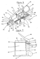
- Figure 5 is an elevated emptying storage tank with front cover and mechanism.
- Figure 6 is a view of a turnstile mechanism for garbage bags.
- Figure 7 is a view of the universal chassis.
- Figure 8 is a view of the floating receiving chest and its anchoring system.
- Figure 9 is a rear view during opening of the side opening system of the cover for drain tank in elevation.
- FIG. 1 represents a centrifugal fan A.
- a disc 2 On the axis 1 of the rotor carried by two bearings located behind the fan and not shown, is welded, in the example, a disc 2. On this disc are welded four identical blades 3. Each plane which contains each of these blades is parallel and external to the axis 1. According to the direction of rotation 4 each of these planes precedes the plane which is parallel to it and which contains the axis 1. Even if each plane which contains each blade intersects the circle 12 - or the main circle in the case of an ellipse - orifice for penetration of the material into the fan, each blade is entirely external to this circle 12.
- each plane which contains each blade is outside or at most tangent to this circle 12.
- the notches 9 in the flange 5 make it possible to lock this flange on the body of the fan. using the wing nuts 10.
- the rotor cage has for its internal section a spiral with two centers: the center 1 naturally and the center 11. These two centers, on parallel axes, are located in a plane parallel to the plane that contains the outer wall of the ejection duct.
- the free part between the rotor and the cage, in particular the crescent 13 is reduced to a minimum compatible with a sufficient ejection section 14.
- the section 14 of the fan is connected to the storage tank by the pipe F - in the drawing only is shown the part of this pipe coupled to the section 14 -.
- the pipe F - in the drawing only is shown the part of this pipe coupled to the section 14 -.
- For this it is fitted on the fan A up to the angle brackets 15.
- Two hooks 16, one on each side, lock it in place. To prevent these hooks 16 from opening unexpectedly, they each have a stop 17 for the parts 18, one on each side, which each rotate freely around their axis 19. To unhook the parts 18 are lifted, which releases the hooks 16.
- FIG. 2 represents an example of a reservoir B for storing the product collected with a drain flap.
- the hatch is shown closed in solid lines and open in dotted lines.
- the tank has, in the example, the parallelipiped shape and an inclined position. This facilitates construction.
- the lower face 20 is obstructed by the hatch 21.
- This hatch is suspended from the arms 22 and 23 by the articulations integral with the tank 24 and 25 on the one hand, and by the articulations 26 and 27 secured by the hatch on the other hand.
- the same arms 22 and 23 are found on the opposite side of the tank and symmetrically.
- the two arms 22 and (or) the two arms 23, are made integral with one another by a junction tube, welded for example.
- a lever arm 28 is secured to the arm 22.
- a tiran 29, articulated at 30 is hooked to the arm 28 by the axis 31. It is secured to the lever 32.
- Both are rotatable at 33.
- a stop 34 prevents the angle formed by the articulated arm at 30 from closing under the thrust of the axis 31, therefore prevents the inadvertent opening of the hatch. This stop is low enough so that the angle cannot be closed by displacement upwards of the articulation 30.
- the arm 29 is released from the stop 34. With the lever the part of the arm 29 which is attached to it rotates around 33. Thus a pull is made on the arm 28 via the axis 31 and the other part of the arm 29.
- the arm 22 rotates around its axis 24. It causes the hatch 21 to disengage which itself rotates the arm 23 around its axis 25.
- the length of the part of the arm 29 which rotates around the axis 33 is preferably such that 'A rotation slightly greater than 180 ° releases the hatch 21 completely from the opening 20 of the tank to position it in full opening - with dotted lines in the drawing -.
- This position is obtained by a judicious ratio of the respective lengths of the arms 22 and 23.
- the part of the tie rod 29 which is attached at 31 to the arm 28 then bears on the stop 34 thus preventing the fall of the hatch. It is then necessary to pull the lever 32 in the opposite direction to the arrow 35 to lower the hatch again.
- a judicious drawing consists in making so that the lowered vertical of the center of gravity of the hatch, when it is open, falls on the same side of the tank with respect to the axis 25. Thus by itself the hatch is held automatically opened.
- FIG. 3 shows a detail of the device of the axis 33 of rotation of the lever.
- this lever is adjustable in length and in angular and lateral position.
- the technique consists in using a secondary shaft 36 with a length at least equal to the maximum lateral offset desired. At the end of this shaft is fixed - preferably by welding - one of the parts of a clamping device 37 - in the example shown we use a standardized cable clamp -. This device is used to lock the lever 32 in the desired position. Its length is thus adjusted.
- this lever is made of round iron and it is seen at the end.
- This shaft 36 is itself blocked in an adequate position by a similar clamping device 38 - also a cable clamp in the example shown -.
- this cable clamp 38 integral with the arm 29 which is welded to one end of the axis 33.
- the tube 39, fixed to the reservoir serves as a bearing for the axis 33 .
- Figure 4 shows a top view and schematically a baffle device located at the top and inside a storage tank for the product collected.
- This tank can, in the use of this system, be provided full walls. This system separates the air from the product collected.
- a conduit 40 is provided in the upper part of the reservoir B or C, preferably at an angle which simplifies the manufacture.
- This conduit 40 is in communication at one of its ends by the passage 41 with the interior of the reservoir , and at the other end by passage 42 with the open air.
- a baffle system 43 forces the charged air which penetrates through the opening 41 to follow the path materialized by the arrows 44 to exit purified by the orifice 42.
- the internal baffle system advantageously has aspect of a drawer which is pulled by the handle 45 in the direction of the arrow 46 in order to extract the baffles and progressively rid them of the solid product retained by falling into the tank through the opening 41.
- a suitable pipe - not shown - is adapted connecting this orifice to the suction manifold.
- the device partially rotates in a closed circuit.
- the air carrying the product to be picked up is recycled.
- many other devices can be retained, and in particular it is in no way obligatory that the baffle device is located inside the tank.
- a cyclone device can advantageously be used.
- FIG. 5 represents a side view of the whole of the hydraulic device allowing the overflow in height of the tank C for storing the picked up product.
- the fan and the supply duct have not been shown.
- the whole is shown the movement in elevation being clearly initiated.
- a vertical post 48 is fixed, naturally there is the same symmetry on the other side of the tank C.
- These two arms 50 are rigidly linked together by the tube 51, a tube seen at the end and in dotted lines in the drawing.
- the tank C is fixed to its arms 50 by the axis 52, the lifting and dumping axis.
- the lower part of the reservoir C is guided by two rollers 53 - one on each side - which are integral with it.
- the arm 50 turns upwards around its axis 49 and this until the stop 59 - in the example an adjustable screw - two stops 59, one on each side.
- the rollers 53 guides from the bottom of the tank, climb along the posts 48 then the guides 54.
- the stop 59 which limits upward the movement of the arms 50, therefore of the axis 52, will allow the residual stroke to be used from the cylinder to the tank spill rotation.
- the axis 52 momentarily becomes a fixed point and the axis 58 will describe an arc of a radius equal to the fixed distance between the two axes 52 and 58 and of a value sufficient to ensure a total discharge of the reservoir.
- the tension spring 60 This has one of its ends attached to the reservoir in 61 and the other to the arm 50 via the small arm 62.
- This small arm 62 is rotatable about its axis 63 anchored on 50. Its other end is hooked at 64 to the spring 60, a stop 65 fixed on the arm 50 limits the rotation of the arm 62.
- the spring 60 attached to the reservoir at 61 accompanies this rotation without enter tension. It is only when the arm 62 bears against the stop 65 that the spring acts. This stop 65 is positioned so that this occurs a few degrees before the lowered vertical of the center of gravity of the tank C passes beyond the axis 52. In this way when the jack 55 begins its reentry, before the axis 52 does the same, the spring 60 recalls the reservoir C in position such that the vertical lowered from its center of gravity passes on the same side as the axis 58 relative to the axis 52. The end of the rotation of the reservoir It is then ensured by gravity. The roller 53 is supported on its guide 54 and the reservoir C descends to the filling position.
- the axis 66 of the cover 67 is not integral with the tank C but with the chassis 47 by means of the posts 48 and of the arm 68 which is welded to the post 48, naturally a set of parts on each side of the tank.
- This axis 66 attached to the cover by the part 69 therefore has a fixed position relative to the chassis.
- the part 69 is extended up to the axis 70.
- This axis is connected by the tiran 71 and the axis 72 to the arm 50.
- the upward movement of the arm 50 causes the opening of the cover 67.
- the ratio of distances between the axes 66 and 70 on the one hand, and 49 and 72 on the other hand is such that the rotation of the arm 50 up to the stop 59, corresponds to a total opening of the cover.
- the length of the tiran 71 is such that at the low filling position of the tank C corresponds a closure total and rigid of the cover 67. In this position the angle formed by the straight line which joins the axes 66 and 70 and the one which joins 72 and 70 is the most closed angle possible, while the angle formed by the right which joins the axes 49 and 72 and that which joins the axes 72 and 70 is an angle close to the right angle. This position allows rapid release of the cover 67 as soon as the reservoir C. is put up.
- the reservoir C fits into the cover 67.
- the top of the cover is provided of a certain height. On the blank of the cover taking advantage of this height, at best on the top is provided the orifice 73 for penetration of the product picked up and ejected by the fan A.
- Figure 6 shows a turnstile system attached to the frame 47 for four recovery bags.
- an arm 74 which carries the vertical axis 75. This axis receives the turnstile.
- a central tube 76 axis of the turnstile obstructed at its upper part is freely fitted on the axis 75.
- the closure of the tube 76 is supported on the upper end of the axis 75.
- a lower square frame 77 - in the example, for lightness in angles and mesh - is integral with the lower end of the tube 76. It is the lower support of the bags.
- An upper square frame 78, in angles, is integral with the upper end of the tube 76. It carries four conventional systems 79 for fixing the bags.
- FIG. 7 shows an example of a universal chassis. This is essentially composed of a square tube 47 of appropriate section and very thick. On this tube at one end, the fan A is fixed. Generally this fixing is done by bolts and oblong holes for the tension of the belts. In the example, the fan A is rotated by a power take-off, not shown, through the bearings 84, the pulley 85 and the belt 86. On each side of the bearings 84 and in their immediate vicinity two uprights 87 welded to the tube 47 can receive an upper axis 88 supporting the device.
- FIG. 8 represents a reception box D produced according to the invention and positioned according to the invention on the casing of the mower E.
- This trunk D has a height H significantly greater than the height h of the highest mower currently in use. This allows it to be adapted to any mower regardless of its height.
- the gaping opening between the top of the mower E and the upper wall of the trunk D due to this difference in height is obstructed by the sheet metal 102.
- the height of this sheet metal 102 is greater than H - h ′ (h ′ being the lowest height of the mower on the market).
- Its length is equal to the length of the opening for the entry of the lawn into the trunk D. This length is greater than the length of the section of the ejection opening of the mower having, on the market, the largest ejection width. This feature makes it possible to always obtain an air inlet orifice 101 whatever this width.
- This sheet 102 is mounted integral with the mower and it carries and guides the trunk D.
- This section 105 serves as a slide for the heads of the bolts 106.
- the nuts 107 allow these bolts 106 to be locked in the appropriate place. These bolts 106 are on the other hand locked between two nuts on the pieces 104 through the oblong holes of these pieces 104.
- the sheet 102 can be positioned ideally at the outlet of the adjustable mower as it is along the three axes.
- the axes 111 are of different lengths which allows the assembly to position them successively and not simultaneously.
- a swivel wheel 114 adjustable in height by the threaded rod 115 ensures perfect positioning of the trunk D relative to the ground, this trunk being free in height relative to the mower E.
- the rod 116 positioned in two of the adequate holes drilled in the arms 108 limit the downward movement of the trunk D when the mower is raised by a stop on this rod 116 of the arms 110. These holes, in the example five in number, on the parts 108, are judiciously drilled in an arc to obtain regular adjustment intervals.
- the trunk D which can oscillate around the axes 111 is held in place at the outlet of the mower therefore against the plate 102 by the slides 117.
- These U-shaped slides 117 are integral with the trunk D and use the vertical ends of the plate 102 as a guide.
- the profile 105 stops a few centimeters from the vertical edges of the sheet 102.
- the trunk D can freely go up and down relative to the mower but cannot move forward or in back from it or deviate from it.
- the end 99 of the box on which the flexible helical pipe is fitted and which will connect it to the fan has an external surface provided in relief with a thread pitch corresponding to the pitch of the pipe.
- the flexible hose can be easily screwed onto this end piece 99. The same applies to the other connections of the apparatus whether the flexible hose is male or female.
- FIG. 9 represents, during the maneuver and rear view, an example of a system for opening the side of the cover for a drain tank in elevation.
- the hinge 118 of the cover 119 is located above the fan A. Its axis is parallel to the direction of travel. This hinge 118 is integral with the chassis 47 by means of the corresponding post 48 on which the support 120 of the hinge 118 has been fixed. Naturally, the cover 119 has an opening 121 for entry towards the tank C of the grass ejected by the fan. A through the conduit F.
- the ball end 122 of the rod 123 for positioning the cover 119 is fixed, at the end of the corresponding lifting arm 50 - in the figure seen at the end - and preferably slightly beyond the axis 52 of anchoring the tank C on the arm 50.
- the other end 124 of the rod 123 also with ball 119 is integral with the cover 119.
- the junction ball 124 is located, when the cover is closed, it that is to say the tank being in the low position, near the corresponding upper edge of the tank.
- the radius of rotation of the ball joint 122 on the arm 50 around the axis 49 - not shown in this figure - is greater than the radius of rotation of the anchor point 52 of the tank, from the start of lifting the cover 119 s 'opens faster than the tank C. will mount.
- the length of the rod 123 corresponds to a total closure of the cover 119, the tank C being in the low position.
- the length of the arm 120 relative to that of the rod 123 is such that a total opening of the cover is obtained for complete movement from the bottom to the top of the arms 50 to their stop 59 - not shown in this figure - limiting the elevation of the tank C before spillage.
Landscapes
- Life Sciences & Earth Sciences (AREA)
- Environmental Sciences (AREA)
- Harvester Elements (AREA)
Abstract
Description
La présente invention concerne un appareil pour le ramassage du gazon, des feuilles mortes et autres souillures du sol. L'appareil peut être porté sur véhicule d'entretien, sur tracteur, il peut être tracté, voir auto-moteur.The present invention relates to an apparatus for collecting grass, dead leaves and other soil from the soil. The device can be worn on a maintenance vehicle, on a tractor, it can be towed or even self-propelled.
Une telle machine est généralement composée des principaux éléments suivants :
- un ventilateur destiné à aspirer le produit à ramasser pour l'emmagasiner dans un réservoir.
- un réservoir qui peut être soit une hotte à vidange par simple trappe, soit une hotte montée sur vérins hydrauliques pour déversement en hauteur dans une remorque ou un camion. Ce réservoir peut être également une remorque attelée derrière le système d'aspiration. Il peut être aussi tout simplement un sac poubelle.
- un chassis support reliant ensemble les éléments ci-dessus et permettant éventuellement de les rattacher au porteur.
- un système collecteur du produit à ramasser. Le collecteur peut être soit un coffre de réception ancré à la sortie du gazon d'une tondeuse, soit un balai ramasseur, voir le brevet Charpenet n° 86 12263, soit une simple bouche d'aspiration.
- un ensemble de conduits reliant le ventilateur d'une part au collecteur et d'autre part au réservoir.
- un ensemble destiné à assurer la rotation du ventilateur. Celle-ci sera obtenue soit par prise de force avec ou sans arbre de transmission, avec ou sans courroie intermédiaire, soit par moteur auxilliaire.
- a fan intended to suck up the product to be picked up to store it in a tank.
- a tank which can be either a hood with emptying by simple hatch, or a hood mounted on hydraulic cylinders for dumping in height in a trailer or a truck. This tank can also be a trailer hitched behind the suction system. It can also be quite simply a trash bag.
- a support frame connecting the above elements together and possibly allowing them to be attached to the carrier.
- a product collection system. The collector can be either a reception chest anchored at the exit of the lawn of a mower, or a pick-up broom, see Charpenet patent n ° 86 12263, or a simple suction mouth.
- a set of conduits connecting the fan on the one hand to the collector and on the other hand to the tank.
- an assembly intended to ensure the rotation of the fan. This will be obtained either by PTO with or without drive shaft, with or without intermediate belt, or by auxiliary motor.
L'existence et l'ensemble de ces éléments réunis dans une même machine est connu. Malheureusement, dans l'état actuel de la technique, plusieurs présentent un certain nombre d'inconvénients, dont la globalité est particulièrement néfaste à une utilisation rationnelle et rentable de l'appareil.The existence and all of these elements gathered in the same machine is known. Unfortunately, in the current state of the art, several have a certain number of drawbacks, the overall nature of which is particularly harmful to rational and profitable use of the device.
Dans les appareils connus le conduit d'amené, généralement en plastique, est relativement rigide. Malheureusement ce système ne permet qu'un faible et insuffisant déplacement du collecteur par rapport au ventilateur. La présente invention a pour bojet l'utilisation d'un conduit d'aspiration doté d'au moins un manchon souple. Dans une forme préférentielle ce conduit est composé d'un fil rigide formant ossature enroulé dans la forme hélicoïdale et noyé dans une enveloppe en matière plastique simple.In known devices, the supply duct, generally made of plastic, is relatively rigid. Unfortunately, this system allows only a small and insufficient displacement of the collector relative to the fan. The subject of the present invention is the use of a suction duct provided with at least one flexible sleeve. In a preferred form, this conduit is composed of a rigid wire forming a framework wound in the helical shape and embedded in a simple plastic envelope.
Hors mis le brevet Charpenet n° 86 12263 et le certificat d'addition n° 87 03360 les ventilateurs connus et destinés à cet usage présentent tous les principaux inconvénients suivants : bourrage par enroulement de la matière aspirée autour des pales du rotor, bourrage par formation de pains à l'intérieur du stator, nettoyage malaisé par démontage fastidieux du capot du stator et non écoulement des eaux de nettoyage.
Par le brevet Charpenet n° 86 12263 et le certificat d'addition n° 87 03360, on sait faire un ventilateur répondant parfaitement aux éxigences spécifiques du ramassage du gazon ou des souillures du sol. Il s'agit d'un ventilateur centrifuge dont les pales du rotor, ou dont les extrémités intérieures et extérieures de chaque pale en cas de pales incurvées, sont chacunes dans un plan qui est parallèle et extérieur à l'axe de rotation du rotor. Ce plan, suivant le sens de rotation du rotor, précéde le plan qui lui est parallèle et qui passe par cet axe. Ainsi les pales sont essentiellement propulsives. Dans ce même brevet on perfectionne cette technique en prévoyant que les plans qui contiennent chaque pale sont extérieurs ou au plus tangents au cercle, ou au cercle principal en cas d'ellipse, d'orifice de pénétration de la matière dans le ventilateur. Ainsi aucune pale n'encombre la partie centrale du rotor correspondant à l'orifice de pénétration de la matière aspirée. Il n'y a pas d'enroulement possible de la matière aspirée autour de ces pales. Dans ce même brevet on améliore considérablement la difficile et fastidieuse opération de nettoyage par l'usage d'attaches rapides pour le montage et le démontage du capot qui porte la goulotte de pénétration du produit aspiré. La conception de ce capot et du stator du ventilateur sont tels que le capot, lorsqu'il est monté, chevauche par l'intérieur, côté éjection, la cage elle-même du rotor. Ainsi on supprime, côté refoulement, tout obstacle à l'écoulement de la matière. La conception de la cage elle-même du ventilateur est telle que, lorsque le capot est enlevé, aucun rebord résiduel ne fait obstacle à l'écoulement des eaux de nettoyage.Excluding the Charpenet patent n ° 86 12263 and the certificate of addition n ° 87 03360, the known fans intended for this use have all the following main drawbacks: stuffing by winding the material sucked around the rotor blades, stuffing by formation of rolls inside the stator, difficult cleaning by tedious dismantling of the stator cover and no drainage of cleaning water.
By the Charpenet patent n ° 86 12263 and the certificate of addition n ° 87 03360, we know how to make a fan that perfectly meets the specific requirements of grass collection or soil soils. It is a centrifugal fan whose rotor blades, or whose inner and outer ends of each blade in the case of curved blades, are each in a plane which is parallel and external to the axis of rotation of the rotor. This plane, according to the direction of rotation of the rotor, precedes the plane which is parallel to it and which passes by this axis. Thus the blades are essentially propulsive. In this same patent, this technique is perfected by providing that the planes which contain each blade are outside or at most tangent to the circle, or to the main circle in the event of an ellipse, orifice for the penetration of material into the fan. Thus, no blade obstructs the central part of the rotor corresponding to the orifice of penetration of the suctioned material. There is no possible winding of the material sucked around these blades. In this same patent, the difficult and tedious cleaning operation is considerably improved by the use of quick fasteners for mounting and dismounting the cover which carries the penetration chute for the aspirated product. The design of this cover and of the fan stator are such that the cover, when mounted, overlaps from the inside, on the ejection side, the cage itself of the rotor. Thus, on the delivery side, any obstacle to the flow of the material is removed. The design of the fan cage itself is such that, when the cover is removed, there is no residual edge preventing the flow of cleaning water.
Le certificat d'addition n° 8703360 au brevet cité ci-dessus n° 8612263 améliore encore la technique de ce ventilateur par l'utilisation d'une cage de stator à section cylindrique ou à section spirale à deux centres situés dans un plan parallèle au plan qui contient la paroi extérieure du conduit d'éjection. Ainsi on supprime ou tout au moins on diminue au maximum la partie libre entre rotor et stator là où il y a possibilité de formation de pains par agglomération du gazon humide.The certificate of addition no. 8703360 to the patent cited above no. 8612263 further improves the technique of this fan by the use of a stator cage with cylindrical section or with spiral section with two centers situated in a plane parallel to the plane which contains the external wall of the ejection duct. Thus, the free part between rotor and stator is eliminated or at least reduced as much as possible where there is the possibility of loaf formation by agglomeration of the wet grass.
L'application de cette technique de ventilateur concerne tout appareil pour le ramassage du gazon, des feuilles mortes et d'autres souillures du sol entrant dans le cadre de la présente invention.The application of this ventilator technique relates to any device for collecting grass, dead leaves and other soil stains within the scope of the present invention.
Dans les appareils connus, lorsque la hotte est à vidange par trappe, celle-ci est montée sur charnières à la manière d'une simple porte avec verrou de fermeture. Il en résulte un système compliqué de verrouillage et une ouverture difficile et brutale de la trappe de vidange en raison de la charge de la matière emmagasinée sur cette trappe. Par le brevet Charpenet n° 8612263 on sait faire une trappe de vidange, non plus simplement ouvrante par rotation, mais escamotable et qui se tient automatiquement fermée ou automatiquement ouverte sans l'adjonction du moindre verrou. La trappe, essentiellement suspendue à quatre bras, deux par deux de longueurs différentes, s'escamote et ne tourne pas autour d'un seul axe. Ceci rend le mouvement d'ouverture indépendant de la charge qui pèse sur elle et ceci supprime toutes forces de frottement. La longueur de ces bras et les positionnements de leurs points de rotation sont tels, qu'en les faisant pivoter, la trappe se décolle légérement de son contact avec la hotte et vient se placer en arrière de celle-ci.In known devices, when the hood is emptied by hatch, the latter is mounted on hinges in the manner of a simple door with closing lock. This results in a complicated locking system and a difficult and abrupt opening of the drain flap due to the load of the material stored on this flap. By the Charpenet patent n ° 8612263 we know how to make a drain hatch, no longer simply opening by rotation, but retractable and which is held automatically closed or automatically opened without the addition of any lock. The hatch, essentially suspended from four arms, two by two of different lengths, retracts and does not rotate around a single axis. This makes the opening movement independent of the load weighing on it and this eliminates all friction forces. The length of these arms and the positions of their points of rotation are such that, by rotating them, the hatch comes off slightly from its contact with the hood and is placed behind it.
L'application de cette technique de trappe de vidange concerne tout appareil pour le ramassage du gazon, des feuilles mortes et autres souillures du sol, entrant dans le cadre de la présente invention.The application of this emptying hatch technique concerns everything apparatus for collecting grass, dead leaves and other soil from the soil, within the scope of the present invention.
Dans le brevet Charpenet n° 8612263 la trappe est partiellement maintenue fermée ou ouverte par l'action d'un ou de plusieurs ressorts ancrés chacun d'une part sur un point fixe solidaire de la hotte, d'autre part sur un bras support de la trappe.In the Charpenet patent n ° 8612263 the hatch is partially kept closed or open by the action of one or more springs each anchored on the one hand on a fixed point secured to the hood, on the other hand on a support arm the hatch.
Dans la présente invention on remplacera avantageusement ce ou ces ressorts par un tirant articulé de commande de position de la trappe. Ce tiran est relié, d'une part par l'intermédiaire d'un axe à l'une de ses extrémités, à un bras solidaire d'un des bras de support de la trappe, et d'autre part à l'autre extrémité, rigidement à un levier de position de la trappe. Ce tiran au voisinage de son articulation, prendra appui sur une butée fixe judicieusement positionnée de façon à empêcher la fermeture de son articulation sous l'action intempestive de la trappe et ainsi de façon à empêcher l'ouverture accidentelle de celle-ci. L'angle ayant pour sommet l'articulation du tirant et pour côtés les droites joignant cette articulation d'une part au point d'attache au bras solidaire du bras support de la trappe d'autre part à l'axe de rotation du levier de commande de positionnement de la trappe cet angle, d'une valeur voisine mais inférieure à 180°, ne pourra se refermer sous l'action de la trappe du fait de la butée,mais il le pourra si l'on agit sur le levier. Inversement, en position d'ouverture totale, la même butée empêchera la chute intempestive de la trappe. Seule l'action sur le levier permettra l'abaissement de celle-ci. D'autres particularités sur cette spécificité apparaitront à la lecture de la description et des dessins notamment le réglage de la position du levier de commande de la trappe par rapport à l'opérateur.In the present invention, this or these springs will advantageously be replaced by an articulated tie rod for controlling the position of the hatch. This tiran is connected, on the one hand by means of an axis at one of its ends, to an arm secured to one of the support arms of the hatch, and on the other hand to the other end , rigidly to a door position lever. This tiran in the vicinity of its articulation, will rest on a fixed stop judiciously positioned so as to prevent the closing of its articulation under the untimely action of the hatch and thus so as to prevent the accidental opening of the latter. The angle having for top the articulation of the tie rod and for sides the straight lines joining this articulation on the one hand to the point of attachment to the arm secured to the support arm of the hatch on the other hand to the axis of rotation of the lever of command to position the hatch this angle, of a value close to but less than 180 °, cannot be closed under the action of the hatch due to the stop, but it can if it is acted on the lever. Conversely, in the fully open position, the same stop will prevent the accidental fall of the hatch. Only the action on the lever will lower it. Other particularities on this specificity will appear on reading the description and the drawings, in particular the adjustment of the position of the control lever of the hatch relative to the operator.
Dans les appareils connus les parois du réservoir où l'on emmagasine le produit ramassé sont partiellement constituées de toles perforées, ou autres systèmes de même nature, de manière à assurer l'évacuation de l'air rejeté par le ventilateur et porteur du produit ramassé. Particulièrement en période sec cette technique a pour conséquence indésirable de créer un nuage de poussière tout autour de l'appareil. La présente invention a pour objet d'éviter ce nuage en utilisant un réservoir aux parois pleines et en ménageant à l'intérieur du réservoir, ou communicant avec l'intérieur du réservoir, un système de séparation de l'air et de la matière transportée, ce peut être par exemple un cyclone. Dans la présente invention on utilisera préférentiellement un système à chicanes séparant l'air des particules solides qu'il contient. L'orifice de sortie de ce système débouchera à l'air libre. Un perfectionnement de ce perfectionnement consiste à relier par un tuyau adequat cet orifice de sortie à l'entrée de l'air dans le collecteur du produit à ramasser. Ainsi l'air véhiculé depuis le point de ramassage jusqu'au réservoir circule partiellement en circuit fermé servant d'élément porteur du produit à rammasser. Il y a là un progrés appréciable en ce qui concerne les nuisances par poussière et par décibels. Dans une réalisation préférentielle de l'invention, ces chicanes auront l'aspect d'un tiroir ménagé dans la partie haute du réservoir et logé dans un compartiment spécial. En tirant ce tiroir on débarasse ces chicanes des poussières qu'elles retiennent. L'orifice, dans ce compartiment, d'entrée de l'air dans ces chicanes se trouve naturellement à l'intérieur du réservoir, tandis que l'orifice de sortie donnant vers l'extérieur peut être relié par un tuyau adéquat à l'entrée d'air côté aspiration. Dans un réalisation préférentielle l'orifice de pénétration de l'air dans ces chicanes est dans un plan approximativement horizontal. Et le fait d'extraire le tiroir vers l'extérieur permet de débarrasser successivement toutes les chicanes des corps solides accumulés par chute par gravité à l'intérieur même du réservoir. Ce dispositif permet le nettoyage, si nécessaire, des chicanes en cours de travail sans polluer la surface du ramassage.In known devices, the walls of the tank where the picked up product is stored are partially made of perforated sheets, or other systems of the same kind, so as to ensure the evacuation of the air rejected by the fan and carrying the picked up product. . Particularly in dry periods this technique has the undesirable consequence of creating a cloud of dust all around the device. The object of the present invention is to avoid this cloud by using a tank with solid walls and by providing inside the tank, or communicating with the inside of the tank, a system for separating the air and the transported material. , it can be for example a cyclone. In the present invention, a baffle system separating the air from the solid particles it contains is preferably used. The outlet of this system will open to the air. An improvement to this improvement consists in connecting this outlet orifice to the air inlet in the collector of the product to be picked up by an adequate pipe. Thus the air conveyed from the collection point to the tank partially circulates in a closed circuit serving as a carrier for the product to be picked up. There is an appreciable progress there as regards the nuisances by dust and decibels. In a preferred embodiment of the invention, these baffles will have the appearance of a drawer in the upper part of the tank and housed in a special compartment. By pulling this drawer we get rid of these baffles of the dust they retain. The opening in this compartment for the entry of air into these baffles is naturally inside the tank, while the exit opening to the outside can be connected by a suitable hose to the air inlet on the suction side. In a preferred embodiment, the air penetration orifice in these baffles is in an approximately horizontal plane. And the fact of extracting the drawer towards the outside makes it possible to successively rid all the baffles of the solid bodies accumulated by fall by gravity inside the very tank. This device allows the cleaning, if necessary, of the baffles during work without polluting the surface of the collection.
Dans les appareils connus, lorsque le réservoir est monté sur élévateur hydraulique avec déversement en hauteur, le guidage lors de l'élévation se fait par glissières. Quelque fois il est étonnament confié aux vérins hydrauliques eux-mêmes en utilisant le guidage intrinsèque des tiges de vérin. Dans la première solution le système est cher, encombrant, lourd et peu précis. Dans la seconde, utilisant les vérins à des fins pour lesquels ils n'ont pas été conçus, il provoque une usure prématurée de ceux-ci, voire leur détérioration par flexion et même torsion des tiges de vérin. De plus il est nécessaire d'utiliser au moins deux vérins. Le déversement s'obtient en limitant le mouvement vers le haut du réservoir et en utilisant la dernière partie de la course des vérins pour obtenir le mouvement de rotation du réservoir. Dans les appareils connus le déversement est trés brutal car aucune amorce de rotation n'est prévue avant la fin de la montée. Ainsi pour obtenir une vitesse de mise en hauteur raisonnable on est obligé d'accepter une rotation brutale.In known devices, when the tank is mounted on a hydraulic elevator with overflow, guidance during the elevation is done by slides. Sometimes it is surprisingly entrusted to the hydraulic cylinders themselves using the intrinsic guidance of the cylinder rods. In the first solution, the system is expensive, bulky, heavy and imprecise. In the second, using the cylinders for purposes for which they were not designed, it causes them to wear out prematurely, even their deterioration by bending and even twisting of the cylinder rods. In addition it is necessary to use at least two cylinders. The spill is obtained by limiting the upward movement of the tank and using the last part of the stroke of the cylinders to obtain the rotational movement of the tank. In known devices, the spill is very brutal because no initiation of rotation is planned before the end of the climb. Thus to obtain a reasonable speed of setting one is forced to accept a sudden rotation.
La rotation pour le déversement du réservoir se fait naturellement autour d'un axe situé dans le voisinage de l'arête supérieure du côté du réservoir correspondant au déversement, côté qui se trouve donc en partie basse au moment de la vidange. Dans les appareils connus l'angle de déversement est limité par la nécessité de toujours maintenir la verticale abaissée du centre de gravité du réservoir vide du côté de l'axe de poussée des vérins par rapport à l'axe de rotation du réservoir. Sans cette condition, aprés déversement, au moment de la rentrée des vérins, le réservoir descendrait en position de vidange sans reprendre sa position initiale. De ce fait, l'angle de déversement est maintenu dans des limites incompatibles avec un bon écoulement du produit, surtout lorsque celui-ci est humide et adhére aux parois.The rotation for the discharge of the tank is naturally around an axis located in the vicinity of the upper edge on the side of the tank corresponding to the discharge, side which is therefore in the lower part at the time of emptying. In known devices, the dumping angle is limited by the need to always keep the vertical lowered from the center of gravity of the empty tank on the side of the thrust axis of the jacks relative to the axis of rotation of the tank. Without this condition, after spillage, when the cylinders are retracted, the tank would descend to the emptying position without returning to its initial position. Therefore, the angle of discharge is kept within limits incompatible with a good flow of the product, especially when it is wet and adheres to the walls.
Dans les appareils connus,toujours à vidange en élévation,le couvercle du réservoir est monté sur une charnière solidaire du réservoir lui-même. Cette charnière est située à proximité de l'arête supérieure du côté supérieur du réservoir en position vidange. Au moment du déversement il s'ouvre sous le seul effet de son propre poids. Ce système a trois défauts principaux : premièrement le couvercle par son propre poids participe à la diminution de l'angle de déversement. Deuxièmement dans ce système s'ouvrant de son propre poids il ne peut s'ouvrir au maximum qu'à la verticale et ainsi il entrave l'écoulement du produit à vidanger. Enfin, on sait que le réservoir est alimenté par un conduit venant du ventilateur, au moment de la mise en hauteur il y a désaccouplement de ce conduit d'avec la bouche d'entrée du produit dans le réservoir. Au moment de la remise en position travail cet accouplement doit être à nouveau assuré en sécurité. Cette nécessité exclue le positionnement de cette bouche d'entrée dans le couvercle car celui-ci,libre autour de sa charnière,n'est pas mécaniquement maintenu en position ouverte ou fermée. Ainsi on doit ménager la bouche d'entrée sur le flan du réservoir lui-même. Il y a là une perte importante du volume réel utile par rapport à une alimentation par le couvercle, soit sur le côté, soit sur le dessus,ce qui assure encore un meilleur remplissage par tassement (brevet Charpenet n° 86 12263).In known devices, still emptying in elevation, the tank cover is mounted on a hinge secured to the tank itself. This hinge is located near the upper edge of the upper side of the tank in the emptying position. At the time of the spill it opens under the sole effect of its own weight. This system has three main faults: firstly, the cover by its own weight contributes to reducing the angle of discharge. Secondly, in this system opening with its own weight, it can only open to the maximum vertically and thus it hinders the flow of the product to be drained. Finally, it is known that the reservoir is supplied by a conduit coming from the fan, at the time of setting up there is uncoupling of this conduit from the inlet mouth of the product in the reservoir. When returning to the work position, this coupling must be secured again. This necessity precludes the positioning of this inlet mouth in the cover because the latter, free around its hinge, is not mechanically maintained in the open or closed position. Thus we must spare the inlet mouth on the blank of the tank itself. There is a significant loss of the actual useful volume compared to a supply by the cover, either on the side or on the top, which ensures even better filling by compaction (Charpenet patent n ° 86 12263).
La présente invention améliore sur tout ces points la technique du déversement en élévation. Le guidage au moment de la mise en hauteur du réservoir ne se fait ni par glissières ni par les vérins eux-mêmes mais par un système à bras articulés. Solidaire du chassis, on ménagera de chaque côté du réservoir et à proximité de sa partie supérieure mais de préférence plus haut que l'axe de déversement deux points de rotation situés sur le même axe horizontal parallèle-à l'axe de déversement. Ces points sont les points fixes des bras articulés. Solidairesdu réservoir on ménagera, vis à vis des deux points ci-dessus, deux points de levage et de rotation. Ces deux points, un de chaque côté du réservoir,sont situés sur un même axe horizontal dit axe de déversement. Cet axe est situé à proximité de l'arête supérieure,mais de préférence nettement en dessous,du côté du déversement du réservoir. Deux bras identiques,dits bras articulés de levage, un de chaque côté,relient ces points deux par deux. Dans une réalisation préférentielle de l'invention on utilise un seul vérin de levage et de rotation. Il sera naturellement situé à même distance de chacun de ces bras. Ces deux bras sont solidement reliés l'un à l'autre, par un tube soudé par exemple,de manière à assurer leur identité et simultanéité de mouvement rotatif. La partie basse du réservoir, par patins, rouleaux ou roulettes, un de chaque côté, prend appui sur un guide, un de chaque coté. Ces guides maintiennent le réservoir en position pendant toute la durée de l'élévation. Un vérin à égale distance des deux bras - mais on peut trés bien concevoir un vérin de chaque côté - prend appui en partie basse sur un axe fixe situé à proximité de la partie basse du réservoir et vers le côté de déversement,et en partie haute,généralement côté tige,sur un axe situé en dessous de l'axe de déversement mais déporté vers le réservoir par rapport à cet axe. Ainsi la poussée du ou des vérins soulève le réservoir maintenu dans son mouvement adéquat par, d'une part les bras de levage qui tournent vers le haut chacun autour de son point fixe, d'autre part par les deux guides cités ci-dessus. Deux butées, une de chaque côté du réservoir, limitent le mouvement vers le haut de ces bras, en n'utilisant que partiellement la course du ou des vérins. La course résiduelle sera utilisée pour le déversement. Ce système à leviers articulés est simple à réaliser. Il est mécaniquement trés fiable.The present invention improves on all these points the elevation dumping technique. The guidance when the tank is raised is not done by slides or by the jacks themselves but by a system with articulated arms. Attached to the chassis, on each side of the tank and close to its upper part, but preferably higher than the dumping axis, two rotation points located on the same horizontal axis parallel to the dumping axis will be provided. These points are the fixed points of the articulated arms. In solidarity with the tank, two points of lifting and rotation will be spared, opposite the two points above. These two points, one on each side of the tank, are located on the same horizontal axis called the spill axis. This axis is located near the upper edge, but preferably clearly below, on the side of the tank discharge. Two identical arms, called articulated lifting arms, one on each side, connect these points two by two. In a preferred embodiment of the invention, a single lifting and rotating cylinder is used. It will naturally be located at the same distance from each of these arms. These two arms are securely connected to each other, by a welded tube for example, so as to ensure their identity and simultaneity of rotary movement. The lower part of the tank, by pads, rollers or rollers, one on each side, is supported on a guide, one on each side. These guides hold the tank in position for the duration of the lift. A cylinder at equal distance from the two arms - but we can very well design a cylinder on each side - is supported in the lower part on a fixed axis located near the lower part of the tank and towards the discharge side, and in the upper part , generally on the rod side, on an axis located below the spill axis but offset to the tank relative to this axis. Thus the thrust of the jack (s) lifts the tank maintained in its proper movement by, on the one hand the lifting arms which rotate upwards each around its fixed point, on the other hand by the two guides mentioned above. Two stops, one on each side of the tank, limit the upward movement of these arms, using only partially the stroke of the jack (s). The remaining stroke will be used for the spill. This articulated lever system is simple to implement. It is mechanically very reliable.
Dans une réalisation préférentielle de l'invention, pour obtenir une amorce du déversement bien avant la fin de la course vers le haut ce qui rend moins brutal le déversement et ce qui améliore l'angle de poussée du ou des vérins les deux guides, un de chaque côté du réservoir, qui déterminent la position de la partie basse du réservoir sont inclinés du bas vers le haut du côté opposé à l'axe de déversement par rapport à l'axe de poussée du ou des vérins. Ainsi, au fur et à mesure de la montée, la partie basse du réservoir s'écarte du ou des vérins amorçant le déversement et diminuant l'angle déterminé par l'axe longitudinal du ou des vérins et le rayon de rotation ayant pour centre l'axe de déversement et pour extrémité l'axe de poussée du ou des vérins. Ce système améliore naturellement le rendement de la poussée du ou des vérins au moment du début de la rotation du réservoir.In a preferred embodiment of the invention, in order to obtain an initiation of the spill well before the end of the upward stroke, which makes the spill less abrupt and which improves the thrust angle of the jack or jacks, the two guides, a on each side of the tank, which determine the position of the bottom part of the tank are inclined from the bottom upwards on the side opposite the spill axis relative to the thrust axis of the cylinder (s). Thus, as the climb progresses, the lower part of the tank moves away from the jack (s) initiating the spill and decreasing the angle determined by the longitudinal axis of the jack (s) and the radius of rotation having its center l 'spill axis and for end the thrust axis of the cylinder (s). This system naturally improves the efficiency of the thrust of the jack (s) when the tank starts to rotate.
Ainsi la présente invention consiste en ce que le plan - ou les plans ou au moins l'un des plans s'il y en a plusieurs - qui contient au moins deux positions du système de guidage du bas du réservoir, forme un angle aigu - ou chacun un angle aigu - ouvert vers le haut avec le plan qui contient le système de guidage du haut du réservoir ou qui contient au moins deux positions de ce système et ceci quelque soit le système de guidage, compas, glissières, ou autre. Dans les appareils connus ces deux plans sont ou parallèles ou convergents vers le haut ou confondus.Thus the present invention consists in that the plane - or the planes or at least one of the planes if there are several - which contains at least two positions of the guide system of the bottom of the tank, forms an acute angle - or each one an acute angle - open upwards with the plane which contains the guidance system of the top of the tank or which contains at least two positions of this system and this whatever the guidance system, compass, slides, or other. In known devices these two planes are either parallel or converging upwards or merging.
La présente invention permet d'obtenir un angle de déversement du réservoir assurant l'écoulement de la matière ramassée en toutes conditions. Nous savons que pour obtenir ce résultat, la condition inévitable est que le réservoir ait une rotation telle que la verticale abaissée de son centre de gravité tombe du côté opposé à l'axe de poussée du ou des vérins par rapport à l'axe de rotation. Malheureusement dans ce cas au moment de la descente le réservoir reste en position vidange. La présente invention consiste à placer un ou plusieurs ressorts de rappel assurant la rotation du réservoir vers sa position initiale dès que la pression du ou des vérins est nulle ou inversée et avant descente. Ce ou ces ressorts auront avantageusement une extrémité solidaire du réservoir et l'autre d'un point fixe du système haut de guidage quelque soit ce système. Pour éviter que le ou les ressorts n'entrent en actione prématurément -c'est à dire avant basculement par gravité du réservoir- ce qui aurait pour inconvénient de gêner l'action du ou des vérins et ce qui conduirait à l'emploi de ressorts de dimensions démesurées dans une réalisation préferentielle de l'invention on reliera judicieusement l'une des extrémités de ce ou de ces ressorts à son point d'ancrage non plus directement mais par l'intermédiaire d'un bras partiellement libre en rotation. Une butée de ce bras est positionnée de façon à arrêter sa rotation au moment où le ressort doit commencer à agir.The present invention makes it possible to obtain a dumping angle of the reservoir ensuring the flow of the material collected under all conditions. We know that to obtain this result, the inevitable condition is that the tank has a rotation such that the lowered vertical of its center of gravity falls on the side opposite to the thrust axis of the jack (s) relative to the axis of rotation . Unfortunately in this case at the time of descent the tank remains in the emptying position. The present invention consists in placing one or more return springs ensuring the rotation of the reservoir towards its initial position as soon as the pressure of the jack or jacks is zero or reversed and before lowering. This or these springs will advantageously have one end integral with the tank and the other with a fixed point of the top guide system whatever this system. To prevent the spring or springs from coming into action prematurely - that is to say before tilting of the tank by gravity - which would have the disadvantage of hampering the action of the jack (s) and which would lead to the use of springs oversized in an embodiment preferential of the invention one judiciously connects one of the ends of this or these springs to its anchor point either directly but via a partially free arm in rotation. A stop of this arm is positioned so as to stop its rotation at the moment when the spring must start to act.
La présente invention palie aux nuisances crées par le couvercle dans sa réalisation connue. Dans la présente invention le couvercle n'a plus sa charnière solidaire du réservoir mais du chassis. Le réservoir étant en position de chargement, cette charnière est située au voisinage de l'arête supérieure du côté du réservoir opposé à l'axe de rotation pour le déversement, mais dans la présente invention elle a une position fixe par rapport au chassis de l'appareil. La fermeture ou l'ouverture du couvercle est commandée par un tirant relié d'une part à un bras solidaire du couvercle d'autre part à l'un des bras articulé de relevage, bras support et guide du haut du réservoir et ce en un point judicieux de ce bras. Le rapport de la longuer du bras solidaire du couvercle et de la distance du point d'ancrage du tirant sur le bras de relevage au point de rotation de celui-ci est telle qu'à l'élévation jusqu'à butée du réservoir correspond une ouverture à environ 90° du couvercle. Les positions des bras de levier sont telles que le couvercle s'ouvre d'abord rapidement pour dégager le passage du réservoir puis finit sa course en douceur. Ainsi le couvercle n'accompagne pas le réservoir dans son mouvement d'élévation et de rotation et il est maintenu mécaniquement et rigidement ouvert ou fermé. Ceci permet de prévoir sur le côté du couvercle ou mieux sur le dessus la bouche d'entrée dans le réservoir du produit ramassé.The present invention overcomes the nuisance created by the cover in its known embodiment. In the present invention, the cover no longer has its hinge secured to the tank but to the chassis. The tank being in the loading position, this hinge is located in the vicinity of the upper edge on the side of the tank opposite the axis of rotation for the discharge, but in the present invention it has a fixed position relative to the chassis of the 'apparatus. The closing or opening of the cover is controlled by a tie rod connected on the one hand to an arm secured to the cover on the other hand to one of the articulated lifting arm, support arm and guide from the top of the tank and this in one judicious point of this arm. The ratio of the length of the arm secured to the cover and the distance from the anchor point of the tie rod on the lifting arm to the point of rotation of the latter is such that the elevation to the stop of the tank corresponds to a about 90 ° opening of the cover. The positions of the lever arms are such that the cover opens first quickly to clear the passage of the tank and then finishes its stroke smoothly. Thus the cover does not accompany the tank in its elevation and rotation movement and it is held mechanically and rigidly open or closed. This allows to provide on the side of the cover or better on top the inlet mouth in the tank of the picked up product.
Pour ce type d'appareil l'usage du sac poubelle comme réservoir de réception du produit à collecter est connu. Cette solution est économique de réalisation et d'utilisation. Pour les surfaces relativement modestes elle est assez pratique. Malheureusement les appareils connus utilisent au maximum deux sacs poubelles embarqués. Cela oblige à des arrêts fréquents et à des retours fréquents aux points de collecte des sacs poubelle.For this type of device, the use of the trash bag as a reservoir for receiving the product to be collected is known. This solution is economical to produce and use. For relatively small areas it is quite practical. Unfortunately known devices use a maximum of two on-board garbage bags. This requires frequent stops and frequent returns to garbage bag collection points.
La présente invention a pour objet de palier à cet inconvénient par l'installation sur le chassis de l'appareil d'un tourniquet pouvant recevoir plusieurs sacs-poubelle : 2, 3, 4 ou 5 ou plus. Tous les sacs sont en place sur le tourniquet. Le cul de chaque sac repose sur un support inférieur tandis que la gueule de chaque sac est maintenue en place et béante par un dispositif classique d'ensachage. Le tout peut tourner manuellement autour d'un axe central. Chaque sac passe successivement,et y est stoppé par crabotage,au droit de l'orifice de sortie du produit ramassé et éjecté par le ventilateur.The object of the present invention is to overcome this drawback by installing a turnstile on the chassis of the apparatus which can receive several garbage bags: 2, 3, 4 or 5 or more. All bags are in place on the turnstile. The bottom of each bag rests on a lower support while the mouth of each bag is held in place and gaping by a conventional bagging device. The whole can turn manually around a central axis. Each bag passes successively, and is stopped there by dog clutch, in line with the outlet orifice of the product picked up and ejected by the fan.
Dans les appareils connus le chassis supportant le ventilateur, son système d'entrainement et le réservoir de stockage et, pour les appareils portés, chassis également destiné à relierl'ensemble au porteur, dans ces appareils là, le chassis est trés complexe. De plus il est différent selon qu'il s'agit d'un appareil à réservoir avec trappe de vidange, d'un appareil à réservoir à vidange en élévation ou d'un appareil muni d'un sac poubelle comme réservoir. Il est en outre différent selon que le porteur a ou n'a pas de prise de force. Pour les porteurs à prise de force il diffère d'un appareil à l'autre selon la vitesse de rotation de la prise de force. Pour les porteurs munis d'un attelage trois points standardisé il diffère d'un appareil à l'autre selon la largeur du porteur.In known devices, the chassis supporting the fan, its drive system and the storage tank and, for worn devices, chassis also intended to connect the assembly to the carrier, in these devices, the chassis is very complex. In addition, it is different depending on whether it is a tank device with drain hatch, a tank device with elevated drain or a device with a trash bag as a tank. It is also different depending on whether the carrier has or has no PTO. For PTO carriers it differs from one device to another depending on the speed of rotation of the PTO. For carriers with a standardized three-point hitch it differs from one device to another depending on the width of the carrier.
Il est aisé d'imaginer les problèmes causés par une telle diversité au niveau du constructeur, au niveau du stockiste et au niveau de l'utilisateur lui-même qui est pratiquement contraint de changer d'appareil lorqu'il change de porteur.It is easy to imagine the problems caused by such diversity at the level of the manufacturer, at the level of the stockist and at the level of the user himself who is practically forced to change devices when he changes carriers.
La présente invention a pour objet la conception d'un chassis universel et simple. Dans une réalisation préférentielle de l'invention ce chassis est essentiellement composé d'un tube, carré de préférence, de section appropiée et de forte épaisseur. A une extrémité de ce tube est fixé le ventilateur. La liaison tube - ventilateur se fait de préférence par boulons (en général 4). Les trous de fixation sont oblongs pour permettre la tension des courroies de transmission. De chaque côté de la partie médiane de la partie du tube comprise entre le ventilateur et son autre extrémité il y a deux plaques, fixées par soudure de préférence, et percées chacune d'un trou. Sur ces trous seront fixés toutes pièces destinées à accrocher l'appareil à un porteur et notamment des tourillons normalisés d'attelage trois points. Un troisième point de fixation est obtenu par une des deux pièces montantes fixées,par soudure de préférence, au voisinage de la même partie médiane du tube. Cespièces sont percées chacune d'un trou destiné à recevoir un troisième axe d'ancrage, notamment le troisième point d'un attelage trois points normalisé. Dans une réalisation préférentielle de l'invention sur le tube principal est ensuite fixé selon le cas d'une part :
soit un moteur auxiliaire relié au ventilateur par poulies ou courroies (une ou plusieurs
soit un bloc paliers recevant le mouvement de la prise de force du porteur par l'intermediaire d'un arbre à cardans et le communiquant au ventilateur par un ensemble de poulies et courroies.
D'autre part
Soit un réservoir de stockage à vidange par trappe
Soit un ensemble réservoir de stockage à vidange en élévation et son mécanisme.
Soit un système de tourniquet pour le stockage en sacs poubelle.The present invention relates to the design of a universal and simple chassis. In a preferred embodiment of the invention, this chassis is essentially composed of a tube, preferably square, of suitable section and of great thickness. At one end of this tube is attached the fan. The tube - fan connection is preferably made by bolts (in general 4). The fixing holes are oblong to allow the tension of the transmission belts. On each side of the middle part of the part of the tube between the fan and its other end there are two plates, preferably fixed by welding, and each drilled with a hole. On these holes will be fixed all parts intended to hang the device on a carrier and in particular standardized three point hitch pins. A third fixing point is obtained by one of the two rising parts fixed, preferably by welding, in the vicinity of the same middle part of the tube. These parts are each pierced with a hole intended to receive a third anchoring axis, in particular the third point of a standardized three-point hitch. In a preferred embodiment of the invention on the main tube is then fixed as appropriate on the one hand:
either an auxiliary motor connected to the fan by pulleys or belts (one or more
or a bearing block receiving the movement of the power take-off of the carrier through a cardan shaft and communicating it to the fan by a set of pulleys and belts.
On the other hand
Either a storage tank to drain by hatch
Or an elevated drain storage tank assembly and its mechanism.
Or a turnstile system for storage in trash bags.
Enfin dans cette même réalisation préférentielle sur ce tube principal sont également attachées, si leur existence est nécessaire, les pièces support du collecteur du produit à ramasser.Finally in this same preferred embodiment on this main tube are also attached, if their existence is necessary, the support parts of the collector of the product to be picked up.
En cas d'appareil porté sur tracteur, il est nécessaire, pour ménager un passage au tuyau d'aspiration, que l'origine d'entrée de ventilateur soit dégagée de la roue sur le côté du tracteur. Selon la largeur du tracteur dans la technique connue on est obligé de prévoir plusieurs modèles d'appareils chacun étant adapté à la largeur du porteur. Grâce à un dispositif de déplacement latéral de l'appareil sur le tracteur la présente invention permet de fixer sur le trois points de n'importe quel tracteur un modèle universel de chassis d'appareils selon l'invention quelque soit la largeur du tracteur.In the case of a tractor-mounted device, it is necessary, in order to provide a passage for the suction pipe, that the origin of the fan inlet clear of the wheel on the side of the tractor. Depending on the width of the tractor in the known technique, it is necessary to provide several models of apparatus, each being adapted to the width of the carrier. Thanks to a device for lateral movement of the device on the tractor, the present invention makes it possible to fix on the three points of any tractor a universal model of device chassis according to the invention whatever the width of the tractor.
Dans une forme préférentielle de l'invention le tube chassis de l'appareil est doté de deux plaques percées destinées à recevoir les tourillons normalisés correspondant aux rotules des bras de relevage. Ces tourillons sont des axes d'un diamètre normalisé dont une extrémité est dotée d'un épaulement suivi d'un filetage pour la fixation sur le support et dont l'autre extrémité est percée pour recevoir une goupille d'arrêt. Dans les fabrications connues les deux tourillons sont montés symétriquement par rapport à l'axe du tracteur, soit orientés vers l'extérieur, soit orientés vers l'intérieur. Dans l'invention les tourillons sont montés sur les plaques non plus symétriquement mais avec la même orientation ils sont montés orientés vers le ventilateur pour les tracteurs moins larges et opposés au ventilateur pour les tracteurs plus larges. Ainsi on obtient un réglage latéral - deux positions - du positionnement de l'appareil sur le tracteur. Dans une réalisation préférentielle de l'invention en dotant la partie filetée des tourillons, pour le blocage sur les plaques, d'une longueur suffisante on peut intercaler une bague d'épaisseur soit du côté de l'écrou,ce qui ne change rien au réglage ci-dessus, soit du côté de l'axe entre l'épaulement de l'axe et la plaque ce qui augmente le déport,d'un côté comme de l'autre,déjà obtenu par le montage ci-dessus. Ce système simple, astucieux, permet donc d'obtenir quatre positions latérales de fixation de l'appareil sur le tracteur. Ceci est amplement suffisant pour tous les types de tracteurs existants. Naturellement sans sortir du cadre de l'invention on peut imaginer d'autres systèmes de déport.In a preferred form of the invention, the chassis tube of the device is provided with two perforated plates intended to receive the standardized pins corresponding to the ball joints of the lifting arms. These pins are axes of a standardized diameter, one end of which is provided with a shoulder followed by a thread for fixing to the support and the other end of which is drilled to receive a stop pin. In known manufacture, the two pins are mounted symmetrically with respect to the axis of the tractor, either oriented towards the outside, or oriented towards the inside. In the invention, the pins are no longer symmetrically mounted on the plates but with the same orientation they are mounted oriented towards the fan for narrower tractors and opposite the fan for wider tractors. Thus we obtain a lateral adjustment - two positions - of the positioning of the device on the tractor. In a preferred embodiment of the invention by providing the threaded part of the pins, for blocking on the plates, of sufficient length, a thick ring can be inserted either on the side of the nut, which does not change the above adjustment, either on the side of the axis between the shoulder of the axis and the plate which increases the offset, on one side as on the other, already obtained by the above assembly. This simple, clever system therefore provides four lateral positions for attaching the device to the tractor. This is more than enough for all types of existing tractors. Naturally without departing from the scope of the invention one can imagine other offset systems.
Lorsque l'appareil est accouplé à une tondeuse pour le ramassage du gazon, les dispositifs connus collecteurs du gazon à la sortie de la tondeuse,présentent de nombreux inconvénients. les deux principaux sont, d'abord qu'ils sont fréquemment à l'origine de bourrages intempestifs, et ensuite qu'ils sont spécifiques à chaque tondeuse. Le deuxième certificat d'addition déposé le 05/01/90 au brevet Charpenet n° 8612263 permet de diminuer considérablement les risques de bourrage . Le moyen employé est la constitution sur le coffre de réception, en amont de la zone de pénétratio du gazon d'une prise d'air dirigée vers la paroi d'impact du gazon éjecté par la tondeuse, L'orientation de cette prise d'air est de nature à provoquer un balayage efficace de cette paroi.Pour obtenir, venant de l'extérieur et non de l'intérieur de la tondeuse, un rapide courant d'air, protecteur de cette paroi, la section de cette prise d'air est nettement plus faible que la section, sur le coffre,de l'orifice d'aspiration en communication avec le ventilateur. En cas de gazon très humide il est également prévu de relier cette prise d'air à la tubulure d'échapement du moteur.When the device is coupled to a mower for collecting the lawn, the known devices for collecting the lawn at the outlet of the mower have many drawbacks. the two main ones are, first that they are frequently the cause of untimely jams, and then that they are specific to each mower. The second certificate of addition filed on 05/01/90 to the Charpenet patent n ° 8612263 makes it possible to considerably reduce the risks of jamming. The means used is the constitution on the reception trunk, upstream of the area of penetration of the grass of an air intake directed towards the impact wall of the grass ejected by the mower, The orientation of this intake of air is likely to cause an effective sweeping of this wall. To obtain, coming from the outside and not from the inside of the mower, a rapid current of air, protective of this wall, the section of this intake air is significantly lower than the section on the trunk of the suction port in communication with the fan. In case of very wet grass it is also planned to connect this air intake to the exhaust pipe of the engine.
L'application de cette spécificité sur le coffre de réception concerne tout appareil pour le ramassage du gazon, des feuilles mortes et autres souillures du sol entrant dans le cadre de la présente invention.The application of this specificity to the reception chest relates to any device for collecting lawn, dead leaves and other soil stains within the scope of the present invention.
La présente invention améliore encore cette technique. Le coffre de réception, selon l'invention est obligatoirement doté d'une paroi déflectrice destinée par sa face extérieure à provoquer et à diriger un flux d'air extérieur à le tondeuse - ou éventuellement les gaz d'échappement du tracteur porteur - vers la paroi d'impact du gazon, sur le coffre, et par sa face intérieure à amorcer le nécessaire virage du gazon en directiondu ventilateur. Dans certaines circonstances, humidité et abondance degazon,cette paroi peut donc elle aussi, être le siège d'un amoncellement intempestif de gazon. Suivant le même principe que précédemment, la présente invention consiste à ménager une prise d'air non chargée entre cette paroi déflectrice et la face frontale de la tondeuse. Ainsi il se produit un flux d'air de chaque côté de cette paroi. Celui qui est opposé à la sortie de la tondeuse par rapport à cette paroi, protège la paroi d'impact du coffre de réception. Celui qui se produit le long de cette paroi mais du côté de la sortie de la tondeuse, protège cette paroi deflectrice elle-même.The present invention further improves this technique. The reception box, according to the invention is necessarily provided with a deflecting wall intended by its external face to cause and direct a flow of air outside the mower - or possibly the exhaust gases of the carrier tractor - towards the lawn impact wall, on the trunk, and by its inner side to initiate the necessary turn of the lawn towards the fan. In certain circumstances, humidity and abundance of grass, this wall can also be the seat of an untimely pile of grass. According to the same principle as above, the present invention consists in providing an uncharged air intake between this deflecting wall and the front face of the mower. Thus there is an air flow on each side of this wall. The one opposite the exit of the mower with respect to this wall, protects the impact wall of the reception box. The one that occurs along this wall but on the exit side of the mower, protects this deflector wall itself.
D'autre part, si le coffre de réception, quelque soit par ailleurs sa conception, est mal positionné à la sortie de la tondeuse, un risque fréquent d'obstruction de l'entrée de ce coffre demeure. En effet, ce coffre, quelque soit ses caractéristiques par ailleurs, se présente toujours sous la forme d'un boitier présentant une large ouverture que l'on positionne à la sortie de la tondeuse côté éjection, et dans laquelle s'engouffre le gazon tondu. Un autre orifice de ce coffre est en communication avec le réservoir de stockage par l'intermédiaire d'un tuyau adéquat et quand nécessaire d'un ventilateur - pour les petites machines ce dernier élément n'est pas indispensable -. Ce coffre est donc obligatoirement doté d'une paroi inférieure horizontale et au voisinage du sol. Dans les appareils connus ce coffre est fixé rigidement à la tondeuse sans réglage possible notamment en hauteur et ce de manière à ce que cette paroi, quelque soit la hauteur de tonte, ne touche naturellement jamais le sol. Ainsi, réglée pour une hauteur de tonte minimum, cette paroi s'écarte automatiquement du sol lorsqu'on augmente la hauteur de coupe. Et le risque est là. Le gazon tondu, généralement long, ce qui justifie la hauteur de coupe, s'entasse sur l'arête de cette paroi inférieure et ce jusqu'à l'obstruction totale de l'entrée du coffre.On the other hand, if the reception box, whatever its design, is badly positioned at the exit of the mower, a frequent risk of obstruction of the entry of this box remains. Indeed, this trunk, whatever its characteristics, is always in the form of a box having a large opening which is positioned at the exit of the mower on the ejection side, and into which the mowed grass is engulfed . Another orifice in this trunk is in communication with the storage tank via an adequate hose and when necessary with a fan - for small machines this last element is not essential -. This chest is therefore necessarily equipped with a horizontal bottom wall and in the vicinity of the ground. In known devices, this box is rigidly fixed to the mower without any possible adjustment, particularly in height, so that this wall, whatever the mowing height, naturally never touches the ground. Thus, set for a minimum mowing height, this wall automatically moves away from the ground when the cutting height is increased. And the risk is there. The mowed lawn, generally long, which justifies the cutting height, is piled up on the edge of this lower wall until the total obstruction of the entrance to the trunk.
Dans la présente invention le coffre de réception n'est pas fixé au carter de la tondeuse dans une position unique et non réglable. Dans la présente invention le coffre de réception est réglable en hauteur par rapport à la tondeuse. Sans sortir du cadre de l'invention, on peut imaginer toutes sortes de systèmes pour obtenir ce réglage. On peut notamment utiliser pour la fixation du coffre une série de trous disposés les uns au-dessus des autres. Onpeut aussi remplacer ces trous par une lumière. Dans une réalisation préférentielle de l'invention on utilisera un système de bras articulés. Au-dessus du carter de la tondeuse et solidaire de celui-ci on dispose un axe horizontal et parallèle à la section de la sortie de la tondeuse. Cet axe est l'axe fixe de l'articulation. Au-dessus du coffre et solidaire de celui-ci, donc qui commande sa position, on dispose un autre axe parallèle au premier. Il suffit de relier ces deux axes par deux tirants ou bras articulés,solidaires l'un de l'autre pour obtenir un support flottant du coffre de réception. Un butée réglable permet de régler la hauteur du coffre en fonction de la hauteur de la tonte. Un perfectionnement à ce système consiste à doter le coffre, soit d'un patin d'usure avec talon, soit d'une roulette frontale réglable en hauteur. Ce dernier dispositif a l'avantage d'avoir le coffre de réception toujours parfaitement réglé en hauteur par rapport au sol quelque soit la hauteur de coupe. La butée mentionnée ci-dessus limite alors la position basse du coffre uniquement au moment du relevage de la tondeuse. Elle est réglable parce que le coffre est universel et doit s'adapter à toutes les formes de carter de tondeuse.In the present invention, the reception box is not fixed to the casing of the mower in a single, non-adjustable position. In the present invention, the reception chest is adjustable in height relative to the mower. Without departing from the scope of the invention, one can imagine all kinds of systems to obtain this adjustment. One can in particular use for fixing the trunk a series of holes arranged one above the other. Can also replace these holes with a light. In a preferred embodiment of the invention, a system of articulated arms will be used. Above the casing of the mower and integral with it there is a horizontal axis and parallel to the section of the outlet of the mower. This axis is the fixed axis of the joint. Above the trunk and integral with it, therefore which controls its position, there is another axis parallel to the first. It is sufficient to connect these two axes by two tie rods or articulated arms, integral with one another to obtain a floating support for the reception chest. An adjustable stop allows you to adjust the height of the trunk according to the height of the mowing. An improvement to this system consists in providing the trunk, either with a wear pad with heel, or with a front wheel adjustable in height. This last device has the advantage of having the receiving chest always perfectly adjusted in height with respect to the ground whatever the cutting height. The abovementioned stop then limits the low position of the boot only when the mower is raised. It is adjustable because the trunk is universal and must adapt to all forms of mower deck.
Le coffre peut être maintenu contre la section de sortie de la tondeuse par son propre poids suspendu qu'il est à l'axe situé au-dessus de lui. Il est préférable de le maintenir mécaniquement et avec sécurité contre cette section. Pour permettre le réglage en hauteur décrit ci-dessus il est nécessaire que la hauteur utile du coffre de réception soit nettement supérieure à la plus haute hauteur de la section de sortie des tondeuses connues,sinon l'arête de la paroi horizontale supérieure du coffre deviendrait un obstacle au passage du gazon. De ce fait la partie supérieure du coffre débouche non plus dans la section de sortie de la tondeuse mais au-dessus. Pour éviter trop de perte d'aspiration par ce passage, il sera obstrué. Un moyen simple est l'utilisation d'une tôle verticale d'une longueur au moins égale à la longueur de la section d'entrée du gazon dans le coffre. Cette tôle est fixée au-dessus de la section de sortie de la tondeus et dans le même plan vertical. Dans une réalisation préférentielle de l'invention une astuce de construction consiste à utiliser l'une au mieux les deux extrémités verticales de cette tôle pour guider verticalement le coffre et le maintenir en place. Il suffit de fixer sur le coffre des butées adéquates qui prendront appui et guide sur la tôle. Le démontage, qui pour le netoyage doit être aisé et rapide, se fera en soulevant le coffre assez haut pour que ces butées échappent de la tôle. Dans une réalisation préférentielle de l'invention on remplace l'axe au-dessus du coffre par deux petits axes identiquement positionnés et solidaires du coffre. Ils sont positionnés dans les trous ménagés à l'extrémité correspondante des bras articulés. Ces axes peuvent être également solidaires de chacun des bras articulés et positionnés chacun dans des trous adéquats ménagés dans les pièces de jonction au coffre. Tous deux sont orientés dans le même sens - quel qu'il soit -. On obtient ainsi un accrochage rapide sans goupille ni boulon du coffre de réception à la tondeuse. Les axes sont d'abord emmanchés dans leurs trous respectifs par un déplacement du coffre parrallèlement à la section de sortie de la tondeuse puis les glissières sont introduites sur la tôle guide. Ces glissières par butées en bout de tôle, sont églament conçues pour empêcher alors ce déplacement. Naturellement s'il n'y a qu'une butée pour obtenir ce résultat celle-ci est située vers l'arête de la tôle qui est opposée à l'origine du mouvement mentionné ci-dessus du coffre parallèlement à la section de sortie de la tondeuse. Ainsi le coffre est maintenu en place contre la section de sortie de la tondeuse dans un sens par cette butée et dans l'autre par butée contre les supports des axes. Le démontage sans le moindre outil est instantané. Il est astucieux alors d'équiper le système de deux axes de longueurs différentes car il est plus facile d'emmancher un axe puis l'autre que les deux à la fois.The trunk can be held against the exit section of the mower by its own hanging weight that it is at the axis located above it. It is best to hold it mechanically and securely against this section. To allow the height adjustment described above it is necessary that the useful height of the reception trunk is significantly greater than the highest height of the outlet section of known mowers, otherwise the edge of the upper horizontal wall of the trunk would become an obstacle to the passage of the lawn. Therefore the upper part of the trunk no longer opens into the mower outlet section but above. To avoid too much loss of suction through this passage, it will be obstructed. A simple means is the use of a vertical sheet of a length at least equal to the length of the entry section of the lawn into the trunk. This sheet is fixed above the exit section of the mower and in the same vertical plane. In a preferred embodiment of the invention, a construction tip consists in using one of the two vertical ends of this sheet to best guide the trunk vertically and hold it in place. It suffices to fix on the trunk adequate stops which will take support and guide on the sheet. Disassembly, which for cleaning should be easy and quick, will be done by lifting the trunk high enough for these stops to escape from the sheet. In a preferred embodiment of the invention, the axis above the trunk is replaced by two small axes identically positioned and integral with the trunk. They are positioned in the holes made at the corresponding end of the articulated arms. These axes may also be integral with each of the articulated arms and each positioned in suitable holes made in the parts connecting to the trunk. Both are oriented in the same direction - whatever it is -. This provides rapid attachment without a pin or bolt from the reception box to the mower. The axes are first fitted into their respective holes by a displacement of the trunk parallel to the exit section of the mower then the slides are introduced on the guide sheet. These slides by stops at the end of the sheet are also designed to prevent this displacement. Naturally if there is only one stop to obtain this result, it is located towards the edge of the sheet which is opposite to the origin of the movement mentioned above of the trunk parallel to the outlet section of the lawnmower. Thus the trunk is held in place against the outlet section of the mower in one direction by this stop and in the other by stop against the supports of the axes. Disassembly without any tools is instantaneous. It is therefore clever to equip the system with two axes of different lengths because it is easier to fit one axis then the other than both at the same time.
Dans les appareils connus, le système de fixation du coffre de réception à la tondeuse est spécifique à chaque type de tondeuse. Et il y en a un grand nombre. On sait que toutes les tondeuses sont munies à l'endroit de la sortie du gazon d'un système déflecteur. Ce système est fixé sur le carter de la tondeuse par au moins deux boulons. Lors de la mise en place de l'appareil, ce déflecteur est déposé et le coffre de réception prend sa place. On utilise alors pour le fixer les points d'ancrage originaux du déflecteur, ou d'autres s'ils existent ou bien encore on procéde par modification du carter de la tondeuse, découpage, perçage, soudure, etc... Dans tous les cas, les points d'ancrage disponibles sur le carter de la tondeuse ayant des positions quelconques et ce dans les trois dimensions chaque adaptation est dans les appareils connus spécifique à chaque type de tondeuse. Ceciest commercialement un trés gros handicap.In known devices, the system for fixing the reception box to the mower is specific to each type of mower. And there are many. We know that all mowers are equipped with a deflector system at the place of the exit of the lawn. This system is attached to the mower deck with at least two bolts. When installing the device, this deflector is removed and the receiving safe takes its place. We then use to fix the original anchor points of the deflector, or others if they exist or else we proceed by modification of the mower housing, cutting, drilling, welding, etc ... In all cases , the anchor points available on the housing of the mower having any positions and this in the three dimensions each adaptation is in known devices specific to each type of mower. This is commercially a very big handicap.
Dans la présente invention le coffre de réception est doté d'un dispositif universel de fixation sur la tondeuse c'est-à-dire pouvant se monter sans aucune transformation sur tous les types de tondeuse. Aucune soudure, aucun perçage, aucune pièce spécifique n'est nécessaire. Sans sortir du cadre de l'invention, pour obtenir ce résultat, plusieurs moyens sont possibles. Notamment on peut utiliser une tôle perforée standard, ou une cornière perforée, que l'on fixe à plat sur le carter en utilisant les trous de fixation existants. Il y aura en principe au moins deux trous sur la tôle, ou la cornière, et sur le carter qui seront vis à vis, même si l'on doit employer des boulons plus petits. Sur cette tôle, ou sur cette cornière, on fixe par tous moyens appropriés les pièces qui supportent le coffre de réception. Ce dispositif ne permet pas un réglage de positionnement précis.In the present invention, the reception chest is provided with a universal fixing device on the mower, that is to say which can be mounted without any transformation on all types of mower. No welding, no drilling, no specific part is necessary. Without departing from the scope of the invention, to obtain this result, several means are possible. In particular, it is possible to use a standard perforated plate, or a perforated angle iron, which is fixed flat on the casing using the existing fixing holes. In principle there will be at least two holes on the sheet metal, or the angle iron, and on the housing which will be opposite, even if smaller bolts have to be used. On this sheet, or on this angle iron, the parts which support the reception chest are fixed by any appropriate means. This device does not allow precise positioning adjustment.
Dans une réalisation préférentielle de l'invention on procédera comme suit : utilisant deux trous quelconques du carter de la tondeuse, par exemple ceux libérés par la dépose du déflecteur, on fixe sur le carter deux pattes coudées à 90 °. Ces pattes, du fer plat par exemple, ont chacune un grand côté positionné verticalement et dans lequel on ménage un trou oblong également orienté verticalement. Ces pattes sont bloquées sur le carter de la tondeuse de façon à ce que le ou les plans verticaux qui contiennent les trous oblongs soient parallèles au plan de la section de sortie du gazon de la tondeuse. La position de ces plans, soit du côté de la section de sortie de la tondeuse, soit du côté opposé par rapport aux trous de fixation, est déterminée par l'éloignement de ces trous à cette section. Dans chacun de ces trous oblongs est bloquée par deux écrous - un de chaque côté - une vis, de préférence poëlier, à filetage total. Ainsi la position de chaque tête de vis est réglable tant en hauteur, par les trous oblongs, qu'en distance du plan de section de sortie de la tondeuse par le filetage. Une glissière à l'intérieur de laquelle on peut bloquer les têtes de vis dans toutes positions adéquates, est solidaire de la pièce sur laquelle sont fixées les pièces supports du coffre de réception. Dans une réalisation préférentielle de l'invention la glissière est réalisée en acier profilé à froid de section rectangulaire ouvert. La section intérieure de ce profilé est suffisante pour loger les têtes de vis et l'ouverture du rectangle suffisante pour le passage de la vis. Un écrou permet de bloquer chaque vis sur la glissière. Dans une autre réalisation préférentielle de l'invention cette glissière est solidaire de la tôle verticale positionnée au droit de la section de sortie de la tondeuse et au-dessus du carter. Ainsi cette tôle est maintenue fermement tout en pouvant être au montage positionnée avec précision. Dans une réalisation préférentielle de l'invention l'axe fixe support des bras articulés, auquel est ancré le coffre flottant de réception est solidaire de cette tôle. Pour cela on soudera judicieusement à l'une de leur extrémité deux fers plats sur cette tôle, ces fers plats sont situés chacun dans un plan perpendiculaire à la tôle. A leur autre extrémité un trou permet le passage de cet axe. Dans une autre réalisation préférentielle de l'invention ces fers plats sont, entre la tôle et l'axe, percés d'une série de trous en correspondance deux par deux. Ces trous sont destinés à recevoir une tige. Cette tige, par choix d'un couple de trous, sert de butée réglable aux bras articulés. Ceci permet le réglage de la position basse du coffre de réception au moment du relevage de la tondeuse. Dans une réalisation préférentielle de l'invention ces trous sont disposés à intervalles réguliers suivant un arc de cercle permettant d'obtenir des intervalles réguliers de réglage de la position basse du coffre.In a preferred embodiment of the invention, the procedure will be as follows: using any two holes in the housing of the mower, for example those released by removing the deflector, two legs bent at 90 ° are fixed on the housing. These legs, of flat iron for example, each have a large side positioned vertically and in which there is an oblong hole also oriented vertically. These tabs are locked on the mower housing so that the vertical plane or planes which contain the oblong holes are parallel to the plane of the lawn exit section of the mower. The position of these planes, either on the side of the exit section of the mower, or on the opposite side with respect to the fixing holes, is determined by the distance of these holes from this section. In each of these oblong holes is blocked by two nuts - one on each side - a screw, preferably a potter's, with full thread. Thus the position of each screw head is adjustable both in height, by the oblong holes, and in distance from the outlet section plane of the mower by the thread. A slide inside which the screw heads can be locked in any suitable position, is integral with the part on which the support parts of the reception chest are fixed. In a preferred embodiment of the invention, the slide is made of cold-formed steel of open rectangular section. The internal section of this profile is sufficient to accommodate the screw heads and the opening of the rectangle sufficient for the passage of the screw. A nut is used to lock each screw on the slide. In another preferred embodiment of the invention, this slide is integral with the vertical sheet positioned at the right of the outlet section of the mower and above the casing. Thus this sheet is held firmly while being able to be positioned precisely positioning. In a preferred embodiment of the invention, the fixed axis supporting the articulated arms, to which the floating receiving chest is anchored, is integral with this sheet. For this, one will weld judiciously to one of their ends two flat irons on this sheet, these flat irons are each located in a plane perpendicular to the sheet. At their other end a hole allows the passage of this axis. In another preferred embodiment of the invention, these flat bars are, between the sheet metal and the axis, pierced with a series of holes corresponding in pairs. These holes are intended to receive a rod. This rod, by choosing a pair of holes, serves as an adjustable stop for the articulated arms. This allows the lower position of the reception box to be adjusted when the mower is raised. In a preferred embodiment of the invention, these holes are arranged at regular intervals along an arc of a circle making it possible to obtain regular intervals for adjusting the low position of the trunk.
Dans les appareils du type, le collecteur du produit à ramasser est relié au manchon d'entrée du ventilateur, par un tuyau, ou un système de tuyaux emmanchés en serre sur le manchon du collecteur ou du ventilateur. Des colliers de serrage assurent le maintien. Ce montage est malaisé et peu efficace.In devices of this type, the collector of the product to be collected is connected to the inlet sleeve of the fan, by a pipe, or a system of pipes fitted in a greenhouse on the sleeve of the manifold or of the fan. Clamps provide support. This arrangement is difficult and ineffective.
La surface enveloppante du tuyau souple suivant la présente invention présentant un aspect hélicoïdal c'est-à-dire de pas de vis , la présente invention consiste à doter le manchon correspondant de ce même aspect. Selon que le manchon est mâle ou femelle la surface extérieure de son enveloppe ou la surface intérieure, sur une longueur déterminée, a une forme hélicoïdale ou de pas de vis. Le pas du manchon correspond naturellement au pas du tuyau souple. Ainsi le montage est aisé. On visse le tuyau sur le manchon ou inversement.The enveloping surface of the flexible pipe according to the present invention having a helical appearance, that is to say of threads, the present invention consists in providing the corresponding sleeve with this same appearance. Depending on whether the sleeve is male or female, the outer surface of its envelope or the inner surface, over a determined length, has a helical shape or a thread shape. The pitch of the sleeve naturally corresponds to the pitch of the flexible pipe. So the mounting is easy. We screw the pipe on the sleeve or vice versa.
Naturellement le même dispositif peut être employé en aval du ventilateur, quel que soit la finalité.Of course the same device can be used downstream of the fan, whatever the purpose.
Dans les appareils connus, en sortie rigide du ventilateur, utilisant des brides boulonnées, le nettoyage est malaisé. Dans la présente invention le conduit de soufflage est fixé au ventilateur par attaches rapides - tous types - ce qui facilite le nettoyage.In known devices, at the rigid outlet of the fan, using bolted flanges, cleaning is difficult. In the present invention, the blowing duct is fixed to the fan by quick couplings - all types - which facilitates cleaning.
Enfin pour les appareils à vidange en élévation, il est apparu que pour les tracteurs de puissance modeste l'utilisation d'un couvercle à charnière horizontale fixe frontale engendrait, pour éviter son ouverture au-dessus du conducteur, ce qui est dangereux, un recul prohibitif de la fixation de l'appareil sur le tracteur. Dans une autre réalisation préférentielle de l'invention la charnière du couvercle, toujours solidaire du chassis, est latérale. Son axe est parallèle au sens de marche. Elle sera jusdicieusement située au-dessus du ventilateur et de l'autre côté du conduit d'amené du gazon par rapport au réservoir. Une tige à rotules commande l'ouverture et la fermeture du couvercle. Cette tige est solidaire à l'une de ses extrémités de l'extrémité ou mieux de l'extrémité légérement prolongée du bras correspondant de relevage du réservoir. L'autre extrémité de cette tige est fixée au couvercle. Ainsi l'élévation du réservoir commande l'ouverture du couvercle. La longueur de cette tige et ses points d'ancrage tant sur le couvercle que sur le bras de relevage du réservoir sont tels qu'à l'élévation du réservoir jusqu'au déversement correspond une ouverture totale du couvercle.Finally for elevated emptying devices, it appeared that for modest power tractors the use of a fixed fixed horizontal hinged cover caused, to avoid its opening above the conductor, which is dangerous, a setback prohibitive in fixing the device to the tractor. In another preferred embodiment of the invention the hinge of the cover, still integral with the chassis, is lateral. Its axis is parallel to the direction of travel. It will be located right above the fan and on the other side of the lawn supply pipe relative to the tank. A swivel rod controls the opening and closing of the cover. This rod is integral at one of its ends with the end or better with the slightly extended end of the corresponding arm for lifting the reservoir. The other end of this rod is attached to the cover. Thus the elevation of the tank controls the opening of the cover. The length of this rod and its anchoring points both on the cover and on the lifting arm of the tank are such that the elevation of the tank until the discharge corresponds to a total opening of the cover.
Dans ce qui suit, par des exemples non limitatifs, l'invention est exposée plus en détail.In the following, by nonlimiting examples, the invention is explained in more detail.
La figure 1 représente un ventilateur réalisé selon l'invention.FIG. 1 represents a fan produced according to the invention.
La figure 2 représente un réservoir de stockage avec trappe et mécanisme.Figure 2 shows a storage tank with hatch and mechanism.
La figure 3 est une vue détaillée de l'axe du levier de commande.Figure 3 is a detailed view of the axis of the control lever.
La figure 4 est une vue du sustème à chicanes d'épuration de l'air.Figure 4 is a view of the air cleaning baffle system.
La figure 5 est une vue du réservoir de stockage à vidange en élévation avec couvercle frontal et mécanisme.Figure 5 is an elevated emptying storage tank with front cover and mechanism.
La figure 6 est une vue d'un mécanisme à tourniquet pour sacs poubelle.Figure 6 is a view of a turnstile mechanism for garbage bags.
La figure 7 est une vue du chassis universel.Figure 7 is a view of the universal chassis.
La figure 8 est une vue du coffre de réception flottant et son système ancrage.Figure 8 is a view of the floating receiving chest and its anchoring system.
La figure 9 est une vue arrière en cours d'ouverture du système d'ouverture latérale du couvercle pour réservoir à vidange en élévation.Figure 9 is a rear view during opening of the side opening system of the cover for drain tank in elevation.
La figure 1 représente un ventilateur centrifuge A. Sur l'axe 1 du rotor porté par deux paliers situés derrière le ventilateur et non représentés, est soudé, dans l'exemple, un disque 2. Sur ce disque sont soudées quatre pales identiques 3. Chaque plan qui contient chacune de ces pales est parallèle et extérieur à l'axe 1. Suivant le sens de rotation 4 chacun de ces plans précéde le plan qui lui est parallèle et qui contient l'axe 1. Même si chaque plan qui contient chaque pale est sécant au cercle 12 - ou au cercle principal en cas d'ellipse - d'orifice de pénétration de la matière dans le ventilateur, chaque pale est entièrement extérieure à ce cercle 12. Dans une réalisation préférentielle, représentée à titre d'exemple, chaque plan qui contient chaque pale est extérieur ou au plus tangent à ce cercle 12. La flasque 5 ou est ménagé cet orifice 12, chevauche en 6, côté intérieur, sous la paroi 7 du stator. Elle est maintenue contre cette paroi par les guides 8. Ces guides, soudés sur la flasque 5, sont contre-coudés et se glissent par dessus la paroi 7. Les encoches 9 dans la flasque 5 permettent de verrouiller cette flasque sur le corps du ventilateur à l'aide des écrous à oreilles 10. Dans l'exemple la cage du rotor a pour section intérieure une spirale à deux centres : le centre 1 naturellement et le centre 11. Ces deux centres, sur des axes parallèles, sont situés dans un plan parallèle au plan qui contient la paroi extérieure du conduit d'éjection. Ainsi la partie libre entre le rotor et la cage, notamment le croissant 13, est réduite à un minimum compatible avec une section d'éjection suffisante 14.FIG. 1 represents a centrifugal fan A. On the axis 1 of the rotor carried by two bearings located behind the fan and not shown, is welded, in the example, a
La section 14 du ventilateur est reliée au réservoir de stockage par le tuyau F - sur le dessin seule est représentée la partie de ce tuyau accouplée à la section 14 -. Pour le nettoyage il est bon que ce tuyau se monte et se démonte rapidement. Pour cela il est emmanché sur le ventilateur A jusqu'aux butées en cornière 15. Deux crochets 16, un de chaque côté, le verrouillent en place. Pour empêcher ces crochets 16 de s'ouvrir intempestivement ils présentent chacun une butée 17 aux pièces 18, une de chaque côté, qui tournent librement chacune autour de leur axe 19. Pour décrocher on relève les pièces 18 ce qui libère les crochets 16.The
La figure 2 représente un exemple de réservoir B de stockage de produit ramassé avec trappe de vidange. La trappe est représentée fermée en traits pleins et ouverte en pointillés.FIG. 2 represents an example of a reservoir B for storing the product collected with a drain flap. The hatch is shown closed in solid lines and open in dotted lines.
Le réservoir a, dans l'exemple, la forme parallèlipipédique et une position inclinée. Ceci facilite la construction. La face inférieure 20 est obstruée par la trappe 21. Cette trappe est suspendue aux bras 22 et 23 par les articulations solidaires du réservoir 24 et 25 d'une part, et par les articulations 26 et 27 solidaires de la trappe d'autre part. Naturellement on trouve du côté opposé du réservoir et symétriquement les mêmes bras 22 et 23. Pour éviter que la trappe 21, lorsqu'elle est en mouvement, ne se tourne en travers, les deux bras 22 et (ou) les deux bras 23, sont rendus solidaires l'un de l'autre par un tube de jonction, soudé par exemple. Un bras de levier 28 est solidaire du bras 22. Un tiran 29, articulé en 30 est accroché au bras 28 par l'axe 31. Il est solidaire du levier 32. L'un et l'autre étant rotatifs en 33. Un butée 34 empêche l'angle formé par le bras articulé en 30 de se refermer sous la poussée de l'axe 31, donc empêche l'ouverture intempestive de la trappe. Cette butée est assez basse pour que l'angle ne puisse se refermer par déplacement vers le haut de l'articulation 30. Par contre, en agissant sur le levier 32 dans le sens de la flèche 35, on dégage le bras 29 de la butée 34. Avec le levier la partie du bras 29 qui lui est rattachée tourne autour de 33. Ainsi on fait une traction sur le bras 28 par l'intermédiaire de l'axe 31 et de l'autre partie du bras 29. Le bras 22 tourne autour de son axe 24. Il entraine le dégagement de la trappe 21 qui elle même fait tourner le bras 23 autour de son axe 25. La longueur de la partie du bras 29 qui tourne autour de l'axe 33 est de préférence telle qu'une rotation légérement supérieure à 180° dégage la trappe 21 totalement de l'ouverture 20 du réservoir pour la positionner en ouverture totale - en pointillés sur le dessin -. Cette position est obtenue par un judicieux rapport des longueurs respectives des bras 22 et 23. La partie du tirant 29 qui est rattachée en 31 au bras 28 prend alors appui sur la butée 34 empêchant ainsi la chute de la trappe. Il faut alors opérer une traction sur le levier 32 dans le sens inverse de la flèche 35 pour abaisser à nouveau la trappe. Un dessin judicieux consiste à faire en sorte que la verticale abaissée du centre de gravité de la trappe, lorsqu'elle est ouverte, tombe du même côté du réservoir par rapport à l'axe 25. Ainsi d'elle même la trappe se maintien automatiquement ouverte.The tank has, in the example, the parallelipiped shape and an inclined position. This facilitates construction. The
La figure 3 représente un détail du dispositif de l'axe 33 de rotation du levier. Quelque soit la technique d'ouverture de trappe employée la position adéquate du levier de commande de la trappe change d'un porteur à l'autre en raison des obstacles possibles : ailes de roues ou autre, et même varie suivant la morphologie de l'utilisateur. Dans la présente invention ce levier est réglable en longueur et en position angulaire et latérale. La technique consiste à utiliser un arbre secondaire 36 d'une longueur au moins égale au déport latéral maximum désiré. En bout de cet arbre est fixé - par soudure de préférence - l'une des parties d'un dispositif de serrage 37 - dans l'exemple représenté on utilise un serre cable normalisé -. Ce dispositif sert à bloquer à la position désirée le levier 32. On en règle ainsi sa longueur. Dans l'exemple ce levier est en fer rond et il est vu en bout. Cet arbre 36 est lui même bloqué en position adéquate par un semblable dispositif de sérrage 38 - également un serre cable dans l'exemple représenté -. Ainsi l'arbre 36 avant blocage du serre cable 38 peut se déplacer latéralement et angulairement et on peut bloquer à la position voulue. Il suffit alors de rendre, par soudure de préférence, ce serre cable 38 solidaire du bras 29 lequel est soudé à un extrémité de l'axe 33. Dans l'exemple le tube 39, fixé sur réservoir sert de palier à l'axe 33.Figure 3 shows a detail of the device of the
La figure 4 représente un vue de dessus et shématiquement un dispositif à chicanes situé en haut et à l'intérieur d'un réservoir de stockage du produit ramassé. Ce réservoir peut, dans l'utilisation de ce système, être doté de parois pleines. Ce système sépare l'air du produit ramassé.Figure 4 shows a top view and schematically a baffle device located at the top and inside a storage tank for the product collected. This tank can, in the use of this system, be provided full walls. This system separates the air from the product collected.
Dans la partie haute du réservoir B ou C, de préférence dans un angle ce qui simplifie la fabrication, on ménage un conduit 40. Ce conduit 40 est en communication à l'une de ses extrémités par le passage 41 avec l'intérieur du réservoir, et à l'autre extrémité par le passage 42 avec l'air libre. A l'intérieur de ce conduit un système à chicanes 43 oblige l'air chargé qui pénétre par l'ouverture 41 à suivre le parcours matérialisé par les flèches 44 pour sortir épuré par l'orifice 42. Le système intérieur à chicanes a avantageusement l'aspect d'un tiroir que l'on tire par la poignée 45 dans le sens de la flèche 46 pour extraire les chicanes et au fur et à mesure les débarrasser du produit solide retenu par chute dans le réservoir à travers l'ouverture 41. Avantageusement sur l'orifice 42 on adapte un tuyau adéquat - non représenté - reliant cet orifice au collecteur d'aspiration. Ainsi l'appareil tourne partiellement en circuit fermé. L'air élément transporteur du produit à ramasser est recyclé. Naturellement sans sortir du cadre de l'invention, de nombreux autres dispositifs peuvent être retenus, et notamment il n'est nullement obligatoire que le dispositif à chicanes soit situé à l'intérieur du réservoir. De même un dispositif à cyclone peut avantageusement être utilisé.In the upper part of the reservoir B or C, preferably at an angle which simplifies the manufacture, a
Dans un mode de réalisation de l'invention la figure 5 représente une vue de côté de l'ensemble du dispositif hydraulique permettant le déversement en hauteur du réservoir C de stockage du produit ramassé. Dans cette vue, par clarté, le ventilateur et le conduit d'amené n'ont pas été représentés. Pour la clarté également l'ensemble est représenté le mouvement en élévation étant nettement amorcé.In an embodiment of the invention, FIG. 5 represents a side view of the whole of the hydraulic device allowing the overflow in height of the tank C for storing the picked up product. In this view, for clarity, the fan and the supply duct have not been shown. For clarity also the whole is shown the movement in elevation being clearly initiated.
Sur le chassis tubulaire 47 transversal au sens de marche, est fixé un poteau vertical 48, naturellement on a le même en symétrie de l'autre côté du réservoir C. En haut de ces poteaux deux axes 49, un de chaque côté, reçoivent les bras 50, un de chaque côté. Ces deux bras 50 sont liés rigidement ensemble par le tube 51, tube vu en bout et en pointillés sur le dessin. Le réservoir C est fixé à ses bras 50 par l'axe 52, axe de levage et de déversement. La partie basse du réservoir C est guidée par deux roulettes 53 - une de chaque côté - qui lui sont solidaires. Ces deux roulettes prennent appui dans l'exemple d'abord contre les poteaux 48 eux-même, puis,dès que le couvercle est suffisamment soulevé, c'est-à-dire dès que la rotation du réservoir peut être amorcée, contre les guides 54, un de chaque côté. Ces guides sont positionnés de façon à imprimer au bas du réservoir un mouvement d'écartement par rapport à l'axe 52 donc un mouvement de rotation du réservoir. Le vérin de levage et de rotation 55 prend appui par son axe 56 sur la pièce 57 solidaire du chassis 47. La poussée s'exerce sur le réservoir par l'axe 58. Lorsque le réservoir est en partie basse, c'est à dire de remplissage, la tige du vérin est totalement rentrée. La mise en pression par le fût du vérin fait sortir sa tige, soulève l'axe 58 donc soulève le réservoir C. Le bras 50 tourne vers le haut autour de son axe 49 et ce jusqu'à la butée 59 - dans l'exemple une vis réglable - deux butées 59, une de chaque côté. Naturellement les roulettes 53 guides du bas du réservoir, grimpent le long des poteaux 48 puis des guides 54. La butée 59 qui limite vers le haut le mouvement des bras 50, donc de l'axe 52, va permettre d'utiliser la course résiduelle du vérin à la rotation de déversement du réservoir. L'axe 52 devient momentanément un point fixe et l'axe 58 va décrire un arc de cercle d'un rayon égal à la distance fixe entre les deux axes 52 et 58 et d'une valeur suffisante pour assurer un déversement total du réservoir. Et dans ce cas le centre de gravité du réservoir C va passer de l'autre côté de l'axe 52 et au moment de la descente le réservoir va rester dans cette position. Pour assurer la rotation du réservoir C dès la rentrée de la tige du vérin 55 et avant que l'axe 52 n'amorce sa descente on dispose du ressort de traction 60. Celui-ci a l'une de ses extrémités accrochée au réservoir en 61 et l'autre au bras 50 par l'intermédiaire du petit bras 62. Ce petit bras 62 est rotatif autour de son axe 63 ancré sur50. Son autre extrémité est accrochée en 64 au ressort 60, une butée 65 fixée sur le bras 50 limite la rotation du bras 62. Ainsi pendant tout le début de la rotation du réservoir C, le ressort 60 accroché au réservoir en 61 accompagne cette rotation sans entrer en tension. C'est seulement lorsque le bras 62 prend appui contre la butée 65 que le ressort agit. Cette butée 65 est positionnée pour que cela se produise quelques degrés avant que la verticale abaissée du centre de gravité du réservoir C ne passe au delà de l'axe 52. De cette manière lorsque le vérin 55 amorce sa rentrée, avant que l'axe 52 n'en fasse autant, le ressort 60 rappel le réservoir C en position telle que la verticale abaissée de son centre de gravité repasse du même côté que l'axe 58 par rapport à l'axe 52. La fin de la rotation du réservoir C est alors assurée par gravité. La roulette 53 prend appui sur son guide 54 et le réservoir C redescend en position de remplissage.On the
Dans la présente invention l'axe 66 du couvercle 67 n'est pas solidaire du réservoir C mais du chassis 47 par l'intermédiaire du poteaux 48 et du bras 68 lequel est soudé sur le poteau 48, naturellement un ensemble de pièces de chaque côté du réservoir. Cet axe 66 rattaché au couvercle par la pièce 69 a donc une position fixe par rapport au chassis. La pièce 69 est prolongée jusqu'à l'axe 70. Cet axe est relié par le tiran 71 et l'axe 72 au bras 50. Ainsi le mouvement vers le haut du bras 50 entraine l'ouverture du couvercle 67. Le rapport des distances entre les axes 66 et 70 d'une part, et 49 et 72 d'autre part est tel qu'à la rotation du bras 50 jusqu'à la butée 59, correspond une ouverture totale du couvercle. La longueur du tiran 71 est telle qu'à la position basse de remplissage du réservoir C correspond une fermeture totale et rigide du couvercle 67. Dans cette position l'angle formé par la droite qui joint les axes 66 et 70 et celle qui joint 72 et 70 est un angle le plus fermé possible, tandis que l'angle formé par la droite qui joint les axes 49 et 72 et celle qui joint les axes 72 et 70 est un angle voisin de l'angle droit. Cette position permet un dégagement rapide du couvercle 67 dès la mise en montée du réservoir C. Le réservoir C s'encastre dans le couvercle 67. Pour assurer que sa partie haute ne touche au début du mouvement le haut du couvercle celui-ci est doté d'une certaine hauteur. Sur le flan du couvercle profitant de cette hauteur, au mieux sur le dessus est ménagé l'orifice 73 de pénétration du produit ramassé et éjecté par le ventilateur A.In the present invention the
La figure 6 représente un système à tourniquet fixé sur le chassis 47 pour quatre sacs de récupération.Figure 6 shows a turnstile system attached to the
Sur le chassis 47 est fixé un bras 74 qui porte l'axe vertical 75. Cet axe reçoit le tourniquet. Un tube central 76 axe du tourniquet obstrué à sa partie supérieure est emmanché librement sur l'axe 75. La fermeture du tube 76 prend appui sur l'extrémité supérieure de l'axe 75. Un cadre carré inférieur 77 - dans l'exemple, pour la légéreté en cornières et grillage - est solidaire de l'extrémité basse du tube 76. C'est le support inférieur des sacs. Un cadre carré supérieur 78, en cornières, est solidaire de l'extrémité haute du tube 76. Il porte quatre systèmes classique 79 de fixation des sacs. Soudés au cadre 77 - dans l'exemple en dessous - quatre jeux de butées d'arrêt 80 permettent de positionner successivement chaque système 79 exactement en dessous de l'orifice - non représenté - de sortie de la matière éjectée par le ventilateur. Un levier 81, porté par l'axe 82 solidaire du chassis 47, maintenu en position par le ressort 83, permet le verrouillage et le déverrouillage du tourniquet.On the
La figure 7 représente un exemple de chassis universel. Celui-ci est essentiellement composé d'un tube carré 47 de section appropriée et de forte épaisseur. Sur ce tube à une extrémité, est fixé le ventilateur A. Généralement cette fixation se fait par boulons et trous oblongs pour la tension des courroies. Dans l'exemple la rotation du ventilateur A se fait par prise de force, non représentée, à travers les paliers 84, la poulie 85 et la courroie 86. De chaque côté des paliers 84 et dans leur voisinage immédiat deux montants 87 soudés sur le tube 47 peuvent recevoir un axe supérieur 88 support de l'appareil. De chaque côté également mais à une distance l'un de l'autre correspondant à l'écartement moyen des bras inférieurs d'un système trois points classique, deux pièces 89, chacunes percées d'un trou sont soudées au tube 47. Sur ces plaques sont montés les deux tourillons 90. Mais à la différence du montage classique ces deux tourillons 90 sont montés dans la même orientation et non symétriquement par rapport à l'axe du tracteur porteur. Ainsi lorsqu'ils sont montés comme représenté sur le dessin, orientés vers le ventilateur celui-ci est plus proche de l'axe longitudinal du tracteur, et ce montage convient pour les tracteurs moins larges. Lorsqu'ils sont montés dans l'orientation inverse, mais toujours tous les deux dans la même orientation, le ventilateur est plus éloigné de l'axe longitudinal du tracteur et ce montage convient pour les tracteurs plus larges. On augmente encore l'importance du déport en intercallant une bague 91 entre l'épaulement du tourillon 90 et la plaque support 89 et ce à chaque tourillon et quelque soit l'orientation retenue. En cas de déport intermédiaire - sans bague 91 - celle-ci sera utilement bloquée entre la plaque 89 et l'écrou 92. On obtient ainsi quatre positionnements possibles de l'appareil, ce qui répond à tous les cas de figure.Figure 7 shows an example of a universal chassis. This is essentially composed of a
Sur la partie libre du tube 47 on fixe généralement à l'aide des brides 93 - deux sont représentées - les autres éléments constitutifs de l'appareil notamment le réservoir, non représenté, quelqu'il soit.On the free part of the
La figure 8 représente un coffre de réception D réalisé selon l'invention et positionné selon l'invention sur le carter de la tondeuse E.FIG. 8 represents a reception box D produced according to the invention and positioned according to the invention on the casing of the mower E.
A l'intérieur de la tondeuse E le gazon est électé suivant la flèche 94 à l'intérieur du coffre D contre la paroi d'impact 95. A l'avant du coffre D est ménagée une entrée 96 d'air dirigé suivant la flèche 97 le long de la paroi 95 par le déflecteur 98. Cette entrée d'air 96 a une section trés nettement inférieure à la section 99 d'écoulement du produit vers le ventilateur. Cette entrée d'air 96 peut être reliée - par tuyau métallique souple non représenté - à la tubulure d'échapement du moteur.Inside the mower E the lawn is electrified along the
D'autre part entre la paroi verticale frontale 100 de la tondeuse et la paroi déflectrice 98 est ménagée une entrée d'air 101 dont le flux s'interpose entre cette paroi 98 et le gazon projeté par la tondeuse. Ainsi cette paroi 98 est protégée de toute adhérence possible en cas de gazon humide.On the other hand, between the vertical
Ce coffre D a une hauteur H nettement supérieure à la hauteur h de la tondeuse la plus haute actuellement en usage. Ceci permet de l'adapter à toute tondeuse quelque soit sa hauteur. L'ouverture laissée béante entre le dessus de la tondeuse E et la paroi supérieure du coffre D du fait de cette différence de hauteur est obstruée par la tôle 102. La hauteur de cette tôle 102 la même pour toutes les adaptations, est supérieur à H - h′ (h′ étant la hauteur de la tondeuse la moins haute du marché). Sa longueur est égale à la longueur de l'orifice de pénétration du gazon dans le coffre D. Cette longueur est supérieure à la longueur de la section de l'orifice d'éjection de la tondeuse dotée, sur le marché, de la plus grande largeur d'éjection. Cette particularité permet de toujours obtenir un orifice d'entrée d'air 101 quelque soit cette largeur. Cette tôle 102 est montée solidaire de la tondeuse et elle est porteuse et guide du coffre D.This trunk D has a height H significantly greater than the height h of the highest mower currently in use. This allows it to be adapted to any mower regardless of its height. The gaping opening between the top of the mower E and the upper wall of the trunk D due to this difference in height is obstructed by the
Sur le dessus du carter de la tondeuse on sélectionne deux trous quelconques 103 - il y a toujours au moins les deux trous qui servaient à fixer le déflecteur originel de la tondeuse - où l'on boulonne les deux fers plats équerres 104. Sur la partie verticale de ces pièces 104 il y a deux trous oblongs, un sur chaque pièce. Sur la tôle 102 et dans le sens de sa longueur, est soudé un profilé rectangle ouvert 105 de façon à ce que l'ouverture du rectangle fasse face aux pièces 104. Ce profilé 105 sert de glissière aux têtes des boulons 106. Les écrous 107 permettent de bloquer ces boulons 106 à l'endroit adéquat. Ces boulons 106 sont d'autre part bloqués entre chacun deux écrous sur les pièces 104 à travers les trous oblongs de ces pièces 104. Selon l'éloignement des trous 103 du plan vertical de la section de l'orifice de sortie du gazon de la tondeuse les pièces 104 sont bloquées sur le carter de la tondeuse comme représenté ou suivant une rotation de 180°. Ainsi la tôle 102 peut être positionnée idéalement à la sortie de la tondeuse réglable qu'elle est suivant les trois axes. Sur cette tôle 102 sont soudées les pièces 108 dotées à leur extrémités libres des axes 109, les bras 110 relient ces axes 109 aux axes 111, les axes 111 portent le coffre de réception D par les pièces 112. Les axes 111 sont de longueurs différentes ce qui permet au montage de les positionner successivement et non simultanément.On the top of the mower housing we select two holes any 103 - there are always at least the two holes which were used to fix the original deflector of the mower - where we bolt the two
Solidaire du coffre D par la pièce 113 une roue pivotante 114 réglable en hauteur par la tige filetée 115 assure un positionnement parfait du coffre D par rapport au sol, ce coffre étant libre en hauteur par rapport à la tondeuse E. La tige 116 positionnée dans deux des trous adéquats percés dans les bras 108 limite le mouvement vers le bas du coffre D au moment du relevage de la tondeuse par butée sur cette tige 116 des bras 110. Ces trous, dans l'exemple au nombre de cinq, sur les pièces 108, sont judicieusement percés suivant un arc de cercle permettant d'obtenir des intervalles de réglage réguliers.Attached to the trunk D by the
Le coffre D qui peut osciller autour des axes 111 est maintenu en place à la sortie de la tondeuse donc contre la plaque 102 par les glissières 117. Ces glissières 117 en forme de U sont solidaires du coffre D et utilisent les embouts verticaux de la plaque 102 comme guide. Dans ce but pour laisser le passage aux guides 117 le profilé105 s'arrête à quelques centimètres des bords verticaux de la tôle 102. Ainsi le coffre D peut librement monté et descendre par rapport à la tondeuse mais ne peut pas se déplacer en avant ou en arrière par rapport à celle-ci ni s'en écarter. Pour le démontage il suffit de lever le coffre D jusqu'à ce que les glissières 117 échappent de la tôle 102 et de lui imprimer un léger mouvement en avant (ou en arrière selon le montage) pour que les axes 111 échappent de leurs supports.The trunk D which can oscillate around the
Enfin l'extrémité 99 du coffre sur laquelle est emmanché le tuyau souple hélicoïdal et qui la reliera au ventilateur, présente une surface extérieure dotée en relief d'un pas de vis correspondant au pas du tuyau. Ainsi le tuyau souple peut être aisément vissé sur cet embout 99. Il en va de même pour les autres raccordements de l'appareil que le tuyau souple soit mâle ou femelle.Finally, the end 99 of the box on which the flexible helical pipe is fitted and which will connect it to the fan, has an external surface provided in relief with a thread pitch corresponding to the pitch of the pipe. Thus the flexible hose can be easily screwed onto this end piece 99. The same applies to the other connections of the apparatus whether the flexible hose is male or female.
La figure 9 représente en cours de manoeuvre et vue arrière un exemple de système d'ouverture latérale du couvercle pour réservoir à vidange en élévation. La charnière 118 du couvercle 119 est située au-dessus du ventilateur A. Son axe est parallèle au sens de marche. Cette charnière 118 est solidaire du chassis 47 par l'intermédiaire du poteau correspondant 48 sur lequel on a fixé le support 120 de la charnière 118. Naturellement le couvercle 119 comporte un orifice 121 d'entré vers le réservoir C du gazon éjecté par le ventilateur A à travers le conduit F. A l'extrémité du bras correspondant de relevage 50 - sur la figure vu en bout - et de préférence légérement au delà de l'axe 52 d'ancrage du réservoir C sur le bras 50 est fixée l'extrémité à rotule 122 de la tige 123 de commande de positionnement du couvercle 119, l'autre extrémité 124 de la tige 123 à rotule également est solidaire du couvercle 119. La rotule de jonction 124 est située, lorsque le couvercle est fermé, c'est-à-dire le réservoir étant en position basse, a proximité du bord supérieur correspondant du réservoir. Comme le rayon de rotation de la rotule 122 sur le bras 50 autour de l'axe 49 - non représenté sur cette figure - est supérieur au rayon de rotation du point d'ancrage 52 du réservoir, dès le commencement du levage le couvercle 119 s'ouvre plus vite que ne montera le réservoir C. La longueur de la tige 123 correspond à une fermeture totale du couvercle 119,le réservoir C étant en position basse. La longueur du bras 120 par rapport à celle de la tige 123 est telle qu'on obtient une ouverture totale du couvercle pour un mouvement complet du bas vers le haut des bras 50 jusqu'à leur butée 59 - non représentée sur cette figure - limitant l'élévation du réservoir C avant déversement.FIG. 9 represents, during the maneuver and rear view, an example of a system for opening the side of the cover for a drain tank in elevation. The
Naturellement l'invention n'est pas limitée aux modes de réalisation présentés. Sans sortir du domaine de protection de l'invention de nombreuses modifications demeurent possibles.Naturally, the invention is not limited to the embodiments presented. Without departing from the scope of protection of the invention, numerous modifications remain possible.
Claims (25)
et ou
et ou
et ou
et ou
and or
and or
and or
and or
Applications Claiming Priority (2)
| Application Number | Priority Date | Filing Date | Title |
|---|---|---|---|
| FR9002823A FR2658981B1 (en) | 1990-03-01 | 1990-03-01 | APPARATUS FOR COLLECTING LAWN FROM DEAD LEAVES AND OTHER SOIL SOIL. |
| FR9002823 | 1990-03-01 |
Publications (2)
| Publication Number | Publication Date |
|---|---|
| EP0446103A2 true EP0446103A2 (en) | 1991-09-11 |
| EP0446103A3 EP0446103A3 (en) | 1995-01-11 |
Family
ID=9394431
Family Applications (1)
| Application Number | Title | Priority Date | Filing Date |
|---|---|---|---|
| EP91400540A Withdrawn EP0446103A3 (en) | 1990-03-01 | 1991-02-27 | Apparatus for picking up grass, dead leaves and the like |
Country Status (2)
| Country | Link |
|---|---|
| EP (1) | EP0446103A3 (en) |
| FR (1) | FR2658981B1 (en) |
Cited By (2)
| Publication number | Priority date | Publication date | Assignee | Title |
|---|---|---|---|---|
| FR2703211A1 (en) * | 1993-04-02 | 1994-10-07 | Charpenet Louis Joseph | Storage device for an implement for picking up grass, dead leaves and other mess on the ground |
| ES2136561A1 (en) * | 1997-09-22 | 1999-11-16 | Alvarez Maria Del Mar Anes | Device for picking up excrement and other products |
Citations (14)
| Publication number | Priority date | Publication date | Assignee | Title |
|---|---|---|---|---|
| GB674569A (en) * | 1950-07-15 | 1952-06-25 | John Clark | A collecting machine for cut crops, especially grass or the like |
| US3499275A (en) * | 1967-07-07 | 1970-03-10 | Franklin R Lozen | Grass catcher for lawn mower |
| GB1250955A (en) * | 1969-02-15 | 1971-10-27 | ||
| US4142351A (en) * | 1977-03-03 | 1979-03-06 | Vann Industries, Inc. | Mower discharge boot |
| FR2423968A1 (en) * | 1978-04-28 | 1979-11-23 | Besson Robert | Grass-collection accessory for lawn mower - has engine-driven fan discharging into perforated sack on frame, with suction pipe intake adjacent to cutter discharge |
| US4487007A (en) * | 1983-06-27 | 1984-12-11 | Excel Industries, Inc. | Storage box for mower clippings |
| US4523788A (en) * | 1983-08-15 | 1985-06-18 | Deere & Company | Lift and dump mechanism for a lawn debris collection box |
| FR2571587A1 (en) * | 1984-10-17 | 1986-04-18 | Garnot Guy | Lawn vacuum cleaner |
| US4709541A (en) * | 1984-02-21 | 1987-12-01 | Outboard Marine Corporation | Grass/lawn debris handling system |
| US4718222A (en) * | 1983-07-25 | 1988-01-12 | Lambert Corporation | Universal mower deck boot |
| FR2602953A1 (en) * | 1986-08-22 | 1988-02-26 | Charpenet Louis | Suction device for cut grass and other waste matter on the ground |
| US4761943A (en) * | 1985-02-06 | 1988-08-09 | Parker Sweeper Company | Mobile vacuum system for use with a riding tractor mower |
| FR2611481A2 (en) * | 1986-08-22 | 1988-09-09 | Charpenet Louis | Vacuum cleaner for cut grass and other dirt on the ground |
| US4984420A (en) * | 1988-02-12 | 1991-01-15 | Kubota, Ltd. | Dumping apparatus for grass catcher |
Family Cites Families (16)
| Publication number | Priority date | Publication date | Assignee | Title |
|---|---|---|---|---|
| US2803847A (en) * | 1954-03-05 | 1957-08-27 | Clement P Hobbs | Vacuum tree leaf collection unit |
| US3167330A (en) * | 1957-04-26 | 1965-01-26 | Donald A Draudt | Coupling |
| FR1277258A (en) * | 1961-01-06 | 1961-11-24 | Improvements to pneumatic machines for harvesting olives and others | |
| US3716977A (en) * | 1971-11-08 | 1973-02-20 | Mcdonough Power Equipment Inc | Grass catcher assembly |
| US3987606A (en) * | 1974-01-10 | 1976-10-26 | Outboard Marine Corporation | Grass clipping collection apparatus |
| US4186546A (en) * | 1978-08-18 | 1980-02-05 | Manuel Machado | Disposable bag mounting for a lawn mower |
| DE2947899C2 (en) * | 1979-03-16 | 1985-06-27 | Maschinen-Mohr, Inh. Hermann Mohr, 8836 Ellingen | Mowing device |
| US4608725A (en) * | 1985-02-21 | 1986-09-02 | Proficient Systems, Inc. | Litter retrieving machine |
| DE3539140A1 (en) * | 1985-11-05 | 1987-05-21 | Mohr Hermann Masch | MEASURING DEVICE |
| AU593972B2 (en) * | 1986-01-08 | 1990-02-22 | Bartlem Pty Ltd | An improved grass catcher |
| FR2593349B1 (en) * | 1986-01-27 | 1990-09-28 | Garnot Guy | GRASS CUTTING AND PICKUP DEVICE |
| US4773205A (en) * | 1986-08-01 | 1988-09-27 | Outboard Marine Corporation | Anti-clogging means for bulk material flow duct |
| US4819417A (en) * | 1987-07-22 | 1989-04-11 | F.H. & H. Limited | Grass clipping catcher |
| JPH01206914A (en) * | 1988-02-12 | 1989-08-21 | Kubota Ltd | Dumping device for grass collecting box |
| JPH01206915A (en) * | 1988-02-12 | 1989-08-21 | Kubota Ltd | Dumping device for grass collecting box |
| US4951882A (en) * | 1989-03-21 | 1990-08-28 | Ober Howard R | Combination leaf and lawn debris comminuting vacuum and wood chipper |
-
1990
- 1990-03-01 FR FR9002823A patent/FR2658981B1/en not_active Expired - Lifetime
-
1991
- 1991-02-27 EP EP91400540A patent/EP0446103A3/en not_active Withdrawn
Patent Citations (14)
| Publication number | Priority date | Publication date | Assignee | Title |
|---|---|---|---|---|
| GB674569A (en) * | 1950-07-15 | 1952-06-25 | John Clark | A collecting machine for cut crops, especially grass or the like |
| US3499275A (en) * | 1967-07-07 | 1970-03-10 | Franklin R Lozen | Grass catcher for lawn mower |
| GB1250955A (en) * | 1969-02-15 | 1971-10-27 | ||
| US4142351A (en) * | 1977-03-03 | 1979-03-06 | Vann Industries, Inc. | Mower discharge boot |
| FR2423968A1 (en) * | 1978-04-28 | 1979-11-23 | Besson Robert | Grass-collection accessory for lawn mower - has engine-driven fan discharging into perforated sack on frame, with suction pipe intake adjacent to cutter discharge |
| US4487007A (en) * | 1983-06-27 | 1984-12-11 | Excel Industries, Inc. | Storage box for mower clippings |
| US4718222A (en) * | 1983-07-25 | 1988-01-12 | Lambert Corporation | Universal mower deck boot |
| US4523788A (en) * | 1983-08-15 | 1985-06-18 | Deere & Company | Lift and dump mechanism for a lawn debris collection box |
| US4709541A (en) * | 1984-02-21 | 1987-12-01 | Outboard Marine Corporation | Grass/lawn debris handling system |
| FR2571587A1 (en) * | 1984-10-17 | 1986-04-18 | Garnot Guy | Lawn vacuum cleaner |
| US4761943A (en) * | 1985-02-06 | 1988-08-09 | Parker Sweeper Company | Mobile vacuum system for use with a riding tractor mower |
| FR2602953A1 (en) * | 1986-08-22 | 1988-02-26 | Charpenet Louis | Suction device for cut grass and other waste matter on the ground |
| FR2611481A2 (en) * | 1986-08-22 | 1988-09-09 | Charpenet Louis | Vacuum cleaner for cut grass and other dirt on the ground |
| US4984420A (en) * | 1988-02-12 | 1991-01-15 | Kubota, Ltd. | Dumping apparatus for grass catcher |
Cited By (2)
| Publication number | Priority date | Publication date | Assignee | Title |
|---|---|---|---|---|
| FR2703211A1 (en) * | 1993-04-02 | 1994-10-07 | Charpenet Louis Joseph | Storage device for an implement for picking up grass, dead leaves and other mess on the ground |
| ES2136561A1 (en) * | 1997-09-22 | 1999-11-16 | Alvarez Maria Del Mar Anes | Device for picking up excrement and other products |
Also Published As
| Publication number | Publication date |
|---|---|
| FR2658981B1 (en) | 1992-05-07 |
| FR2658981A1 (en) | 1991-09-06 |
| EP0446103A3 (en) | 1995-01-11 |
Similar Documents
| Publication | Publication Date | Title |
|---|---|---|
| CA2238801C (en) | Riding lawn mower including a cut grass collector | |
| US4167975A (en) | Beach cleaning apparatus | |
| FR2608006A1 (en) | MOWER FIXED IN THE FRONT OF A VEHICLE | |
| FR2931031A1 (en) | LAWN MOWER WITH GRASS COLLECTION UNIT | |
| FR2890287A1 (en) | Insect trap for protecting crops has hood fitted with fans which suck insects up through slot in its base and into horizontal upper section forming trap | |
| FR2860386A1 (en) | GRASS COLLECTOR APPARATUS AND MOWER COMPRISING SAME | |
| FR2862480A1 (en) | Grass collecting system for lawn mower, includes shortening mechanism installed to bottom plate, to shorten distance of plate front end from pivot shaft | |
| FR2940004A1 (en) | Herb collecting device for lawn mower, has blocking mechanism including spring producing retaining and engagement force between engagement axle and hook, and switching mechanism to control force produced by spring | |
| EP3033938B1 (en) | Spooler-baler | |
| WO2020115278A1 (en) | Machine for undoing and dispensing bales of animal litter or bales of fodder | |
| EP3045028B1 (en) | Hopper and holder thereof | |
| EP0446103A2 (en) | Apparatus for picking up grass, dead leaves and the like | |
| FR2537384A1 (en) | Vineyard cultivating tractor with harvesting attachments | |
| FR2522245A1 (en) | Implement for gathering fruit from tree - uses vibrator with ridged pair of panels feeding falling fruit into long containers on each side of tree | |
| EP3413700B1 (en) | Device for collecting plants | |
| EP0843046B1 (en) | Apparatus for sweeping and collecting material | |
| EP3550957B1 (en) | Silo unloader bucket equipped with a means for separating and discharging material | |
| FR2522471A1 (en) | AUTOMATIC UNLOADING HARVESTING TRANSPORT VEHICLE | |
| FR3041946A1 (en) | DEVICE FOR LOADING A RECEPTACLE IN WASTE, SUCH AS A WASTEWATER DUMP FROM A PLATFORM | |
| EP1638386B1 (en) | Storage device for vegetables, in particular leeks, and method therefor | |
| FR2586160A1 (en) | APPARATUS FOR BROADCASTING LAND COMPRISING MEANS FOR TRANSFERRING CUT GRASS TO A COLLECTING CONTAINER | |
| FR3055179B1 (en) | TUBER LOADER | |
| FR2623534A1 (en) | Equipment for picking up rubbish on dirty ground, particularly for cleaning beaches | |
| FR2687533A1 (en) | Device for preparing the land for removing objects therefrom | |
| FR2470531A1 (en) | Tractor mounted stem crop mower - has tipping hopper with inlet port and discharge opening at top in working position |
Legal Events
| Date | Code | Title | Description |
|---|---|---|---|
| PUAI | Public reference made under article 153(3) epc to a published international application that has entered the european phase |
Free format text: ORIGINAL CODE: 0009012 |
|
| AK | Designated contracting states |
Kind code of ref document: A2 Designated state(s): AT BE CH DE ES GB GR IT LI LU NL SE |
|
| RBV | Designated contracting states (corrected) |
Designated state(s): AT BE CH DE ES GB IT LI |
|
| PUAL | Search report despatched |
Free format text: ORIGINAL CODE: 0009013 |
|
| AK | Designated contracting states |
Kind code of ref document: A3 Designated state(s): AT BE CH DE ES GB IT LI Kind code of ref document: A3 Designated state(s): AT BE CH DE ES GB GR IT LI LU NL SE |
|
| STAA | Information on the status of an ep patent application or granted ep patent |
Free format text: STATUS: THE APPLICATION IS DEEMED TO BE WITHDRAWN |
|
| 18D | Application deemed to be withdrawn |
Effective date: 19950712 |