EP0445034B1 - System and use of this system in a card replacement process - Google Patents
System and use of this system in a card replacement process Download PDFInfo
- Publication number
- EP0445034B1 EP0445034B1 EP91400541A EP91400541A EP0445034B1 EP 0445034 B1 EP0445034 B1 EP 0445034B1 EP 91400541 A EP91400541 A EP 91400541A EP 91400541 A EP91400541 A EP 91400541A EP 0445034 B1 EP0445034 B1 EP 0445034B1
- Authority
- EP
- European Patent Office
- Prior art keywords
- message
- program
- application
- presentation
- service
- Prior art date
- Legal status (The legal status is an assumption and is not a legal conclusion. Google has not performed a legal analysis and makes no representation as to the accuracy of the status listed.)
- Expired - Lifetime
Links
Images


Classifications
-
- G—PHYSICS
- G06—COMPUTING; CALCULATING OR COUNTING
- G06F—ELECTRIC DIGITAL DATA PROCESSING
- G06F15/00—Digital computers in general; Data processing equipment in general
-
- G—PHYSICS
- G06—COMPUTING; CALCULATING OR COUNTING
- G06F—ELECTRIC DIGITAL DATA PROCESSING
- G06F11/00—Error detection; Error correction; Monitoring
- G06F11/22—Detection or location of defective computer hardware by testing during standby operation or during idle time, e.g. start-up testing
- G06F11/2294—Detection or location of defective computer hardware by testing during standby operation or during idle time, e.g. start-up testing by remote test
-
- G—PHYSICS
- G06—COMPUTING; CALCULATING OR COUNTING
- G06F—ELECTRIC DIGITAL DATA PROCESSING
- G06F11/00—Error detection; Error correction; Monitoring
- G06F11/07—Responding to the occurrence of a fault, e.g. fault tolerance
- G06F11/16—Error detection or correction of the data by redundancy in hardware
- G06F11/20—Error detection or correction of the data by redundancy in hardware using active fault-masking, e.g. by switching out faulty elements or by switching in spare elements
-
- G—PHYSICS
- G06—COMPUTING; CALCULATING OR COUNTING
- G06F—ELECTRIC DIGITAL DATA PROCESSING
- G06F11/00—Error detection; Error correction; Monitoring
- G06F11/22—Detection or location of defective computer hardware by testing during standby operation or during idle time, e.g. start-up testing
- G06F11/26—Functional testing
- G06F11/273—Tester hardware, i.e. output processing circuits
- G06F11/2736—Tester hardware, i.e. output processing circuits using a dedicated service processor for test
-
- G—PHYSICS
- G06—COMPUTING; CALCULATING OR COUNTING
- G06F—ELECTRIC DIGITAL DATA PROCESSING
- G06F11/00—Error detection; Error correction; Monitoring
- G06F11/22—Detection or location of defective computer hardware by testing during standby operation or during idle time, e.g. start-up testing
-
- G—PHYSICS
- G06—COMPUTING; CALCULATING OR COUNTING
- G06F—ELECTRIC DIGITAL DATA PROCESSING
- G06F11/00—Error detection; Error correction; Monitoring
- G06F11/30—Monitoring
- G06F11/32—Monitoring with visual or acoustical indication of the functioning of the machine
Definitions
- the present invention relates to a device and the use of this device in a card replacement method. It is known for example from European patent application 0 031 782 a device comprising a service processor connected by a network and a channel maintenance unit connected to a central system, said service processor being connected by a console switch. service to a remote service console.
- this remote maintenance or these programs operated remotely are carried out with means having an unsophisticated ergonomics and requiring, on the part of the operator, specific knowledge of the system.
- a first object of the invention is therefore to propose a device allowing the use of a service processor of a central system with good ergonomics, this use possibly being done remotely.
- the device makes it possible to control an application remotely, comprising a first service processor connected by a network and a channel maintenance unit connected to a central system, said service processor being connected by a switch of a service console, to an RMS maintenance service console, and to a remote RSC service console, is characterized in that the service processor and each console additionally comprise operating system programs, a supervisor program and at least one service broken down into two applications, one "body” composed of the program algorithm, the other "presentation" comprising the interface with the operator allowing display of the window type with a menu bar, the application body program comprises a message exchange library module (171) linked to the application body program and containing primitives intended to emit re or to receive messages and the application presentation program comprises windows generated according to the application and stored in a memory, and a message exchange library module (183) linked to the application presentation program and containing primitives intended to receive or transmit messages, the messages received by the message exchange library module linked to the presentation program contain the address of the memory block in which the message is stored and the messages sent
- An additional feature of the invention is to allow the use of the standby processor to present a service which is executed by the holding processor.
- the standby service processor comprises means for running the presentation application corresponding to a service, and means for communicating with the holding service processor comprising the means for running the trunk application at the same time a service, the presentation of which is made on the standby processor, and the trunk application, as well as the presentation of a second service, the presentation of which is made on itself.
- each service processor or console comprises a supervisor program managing the instance numbers of the services, and ensuring the starting of the services.
- each service processor comprises means for processing communications with the other service processor.
- each console comprises means for processing communications by the service console switch with one of the service processors.
- the application of the presentation also consists of displaying in a dialog box a message indicating that the location is occupied, and that the system will try to copy its content, and a question asking for confirmation or stopping the service and to select confirmation or stopping the service, coming click the corresponding block.
- the method consists in displaying in a dialog box the group of elements in which a second element will be selected by bringing a highlighting on this element; to validate the selection by clicking on the block containing the message "OK".
- Another object of the invention is to propose a method of using a program divided into two applications on an information processing device.
- FIG. 20 represents a variant representation of one of the steps of the presentation program for replacing a card corresponding to FIGS. 9 or 12.
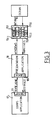
- the architecture of the system is constituted, as shown in FIG. 1, by a service processor holding (1), connected by an interface software (10) MSH (Maintenance Station Handler) with a line for processing maintenance of the telecommunication stations (12) forming a STARLAN type network.
- This line (12) is connected to a clock and maintenance unit (40) which ensures communications between the service processor (1), a second standby service processor, via a second line ( 22), and a central system (41).
- the maintenance and clock unit (40) of a central subsystem (4) also communicates by a line (43) with a set of maintenance processors (42).
- the service processor holding (1) and the service processor standby (2) also communicate via a remote line management interface (11) RLH (Remote Line Handler), and respectively (21), with a service console switch (3), which makes it possible, via a circuit (30), and an appropriate switching matrix, to activate communication each of the service processors with the telecommunication network of a given country, and through this network with a station (5) constituting a remote service console communicating with this network (52) via software 'RSC interface (50).
- each of the service processors can be put in communication, through the network (52), with a remote maintenance station (6) communicating with the network (52) by an RMS interface software (51).
- the lines (23) and (13) connected to the service console switch by the interface software (21) and (11) have bit rates of 4,800 baud, while the lines (12) and (22) form the network STARLAN with the clock and maintenance unit (40) have speeds of the order of megabits per second.
- the maintenance processors (42) are connected to sets of input-output units for the central system.
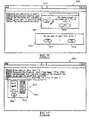
- FIG. 2 represents the software environment allowing the service processors (1, 2) to communicate via the STARLAN network with the maintenance unit (40).
- the service processor holding comprises in addition to the MSH software (10) and an operating system comprising the operating system of the MS-DOS disk, multitasking window software such as WINDOWS, and a part of software that the 'will be described later.
- the service processor holding also includes NETBIOS communication software (100) communicating through a network card STARLAN type (14) and a hardware element (101) constituting a gateway, through the line (12) of the STARLAN network, to a second gateway (400), a management circuit (401), NETBIOS interface software (402) and software for interfacing with the service processor (403).
- the standby service processor (2) will also have the same elements, but with the digit 2 as a reference for the tens or hundreds digit.
- Each service processor additionally includes in its operating system (15, 25) a body program for a given application (17, 27, fig. 1) and a program presenting the application (18, 28, fig. 1 ).
- the remote consoles (5, 6) can be constituted, as for the service processors, of microcomputers having in addition to the keyboard of a mouse, and of an operating system (65, 55) constituted also as for the service processors of the MS-DOS disk operating system, a WINDOWS multi-window software, and an SPV supervisor software, whose role is to launch the presentations in the console (s).
- An LPXMS module makes it possible to store in the LOG and LOGM files of the hard disk respectively the incident messages and all the dialogs of all the services.
- the supervisor of the service processor holding also knows by RLH, the state of connection or disconnection of the consoles to control the console switch (30) accordingly and configure the presentations, as we will see later.
- the maintenance and clock unit makes it possible to launch the second service processor in the event of failure of the first, and the SPV supervisor installs in the latter the same applications.
- These remote stations (5, 6) also include presentation software (58, 68) corresponding to the presentation software of the body programs of an application running on a service processor (1), respectively (2).
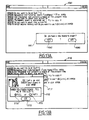
- FIG. 3 represents the principle of the architecture necessary for the implementation of the invention in which the body program (17) of a given application, running for example on the service processor holding, exchanging lines of text and acknowledgment or response messages with the presentation program (18) of the application.
- These exchanges of messages and lines of text are carried out by means of library management modules for messages LBXMS (171) and LPXMS (183) which are linked respectively to the body of the application and to the presentation of the application.
- the presentation program of the application exchanges with the WINDOWS software (150), the primitives necessary for the management of tasks and the display of windows.
- the presentation application will have been developed using the WINDOWS (150) program which can be seen as a set of four components.
- a first kernel component (Kernel) (151) ensuring the management of tasks, allocations of memory, TIMER function and dynamic links.
- a second user element (152) used to manage the windows and create them.
- a third GDI element (153) making it possible to carry out the graphic functions for drawing purposes, and a fourth COM element (154) ensuring the communication functions asynchronously, for example by means of a DDE protocol (dynamic exchange which is a data exchange protocol between applications and allows communication between applications.
- DDE protocol dynamic exchange which is a data exchange protocol between applications and allows communication between applications.
- FIG. 4 represents the operation of the architecture in the case of a service processor holding (1) connected via a service console switch (30) to the remote maintenance console (6) and to the remote service console (5) consisting of a microcomputer.
- This microcomputer like the service processor (1), comprises a mouse and an operating system (550, 551, 552) constituted respectively by the software MS-DOS, WINDOWS and a supervisor SPV.
- the operating system is constituted in the same way by the elements (650, 651, 652).
- An RSC interface (50) provides the interface between the telecommunication lines and the microcomputer (5), and through these telecommunication lines, to the service processor which is itself interfaced with the communication lines by the RLH interface (11).
- the maintenance station includes an RMS interface (60) having the same functions as the RSC interface.
- This RSC interface communicates by a message library module (583) linked to the presentation of the application (58) constituted by a RPB card replacement application (replace board).
- the body of the card replacement application (17) rotates on the holding service processor and is linked to a message library allowing communication with the RLH interface (11).
- the service console switch (30) makes it possible, thanks to a switching matrix and to the information provided by the RLH interface of the holding processor (1), to direct messages coming from the service processor to the two consoles, if these two consoles are connected, to route all the messages sent by the remote service console (5) to the service processor (1) and the maintenance console, if the latter is connected, and to route all the messages issued by the maintenance console to the service processor.
- This is enabled by the fact that RLH, as the consoles are connected, establishes a dialogue with the respective RSC or RMS interface, and notifies the supervisor program (152) the state of connection or disconnection of the consoles from the network. This table is then used to establish communications through the console switch (30).
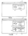
- FIG. 5 represents the operation of the architecture described in the case where the service processor (1) is in communication with a remote console (5).
- This remote console (5) used to present a RPB application (58), thanks to the XMESS library module (583) and to the RSC interface (50) which communicates via the network with the RLH interface (11 ) of the service processor.
- the service processor executes the application body program (17), and the supervisor (152) stores, on a disk (16), in a LOG file (160) and in a LOGM file (161) , respectively the incident messages and all the dialogs of all the services running in the service processor.
- the RLH interface (11) sees the remote stations through the service console switch (30) and conducts only one data communication line connecting RLH and SCC.
- the two data communication lines, linking the service processor with the RMS and RSC stations, are conducted by SCC.
- the service processor (1) can, for example, execute another application called VMP, and thanks to the presentation program of this VMP application, present this application on its monitor, while the second RPB application will be presented on the monitor of the RSC station. At the same time, a dialog copy of the VMP application will be available on the RSC station.
- VMP another application
- the presentation program of this VMP application present this application on its monitor
- the second RPB application will be presented on the monitor of the RSC station.
- a dialog copy of the VMP application will be available on the RSC station.
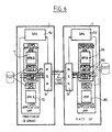
- FIG. 6 represents another advantage of the proposed architecture which makes it possible, for example, to use the standby service processor (2) to make the presentation of an application which is running on the holding service processor (1).
- This has the advantage of allowing use of the standby service processor which, given the increase in the reliability of the hardware, becomes less and less used in its role as standby service processor, and can thus be used. as an additional console for presenting an application.
- the service processor (2) executes the presentation of the RPB application (28), while the body of the RPB application is executed by the service processor holding (1).
- the service processors (1) and (2) communicate with each other via the MSH interfaces (10, 20) and the STARLAN network, as shown in FIG. 2.
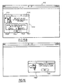
- Figure 7 shows the format of the messages.
- the first type of format corresponds to the messages exchanged between the body of an application and the XMESS library module.
- the format consists of a message number which can be VSH 001, or RPB 120 in the case of the card replacement application, followed by the message text which can be "my prefixed message", where in the case of the card replacement application, "the required space contains a card”.
- the message When the messages are exchanged between the XMESS library modules of two remote interfaces, the message consists of the service name which can be SYC 01, of the instance, followed by the message number and the text as seen above.
- the archived messages shown on the last line, precede the format of the XMESS interface message with the date and time.
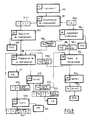
- Figures 8 to 16 show an example of an application whose body and presentation can be separated according to the principle of the invention.
- the first step is to launch the RPB service, indicated by the reference (900).
- This step consists first of making the SPV supervisor service appear in the window to come and select from the menu of different services the replacement of the RPB card, and launch it by clicking on its name with the mouse.
- the first question posed by RPB is to provide it with the identifier of the physical location where the manipulation takes place.
- This step is indicated by step (901) on the flow chart.
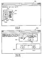
- This step is reflected in the card replacement presentation program by the appearance of a window (9010, fig. 9) inside which is represented a dialog box (9011) comprising a first assembly (9012) consisting of a box of three radio buttons, corresponding to each of the types of elements likely to be replaced.
- This dialog box includes a list box (9013) which, once a type of element has been selected, for example the type of memory units by clicking on the radio button opposite, brings up in the list box, the list of the different elements of the memory unit that can be selected.
- This list appears by a flow system well known to WINDOWS users. Once the type of unit and the identity of this unit selected, the choice is validated by clicking with the mouse on a validation block (9014).
- the body program proceeds to the location requisition step to allow the desired manipulation. If the physical unit present in the chosen location is unavailable, the body program causes the presentation program to display this information and then stops in step (907). The display of this unavailability information is reflected between the body program and the presentation by the exchange of a message referenced "RPB 120" indicating "the required location contains a map at this time”.
- This message processed by the presentation program, causes the appearance of the window (9050, fig. 10) in which a dialog box (9051) contains a figurative element and the sentence of the message, as well as a validation block ( 9052) which, after being clicked with the mouse, allows you to acknowledge receipt of the message, as shown in Figure 17.
- a second dialog box in this window asks the operator if he wants to abort this action, or continue it.
- This second box contains the block (9071) which corresponds to the interruption of the action and diverts the body program to the "end" stage (911, fig. 8).
- a second block (9072, fig. 10) triggers, by a response message sent to the body program, the continuation of the manipulation by the manipulation preparation stage (909, fig. 8) of the body program.
- the RPB body program informs the presentation of the success of the requisition by a message and prepares the manipulation for step ( 909) by indicating to the operator that the system is trying to copy the unused card.
- This is represented in figure 11, by the window (9090) which includes a dialog box (9091), inside which appears a message "the memory card is allocated, we are trying to copy it", and a block validation (9092).
- This window (9090) also includes a second dialog box (9110) in which a first block makes it possible to interrupt the action, as shown in step (911) of FIG. 9, and a second block (9112) allows to continue the action by going to step (913) of the flow diagram of FIG. 9.
- the step of determining the location (901) can optionally be followed by a complementary step information (904), for example in the case where one wishes to copy a memory card to a location on the card intended for copying.
- This step triggers in the presentation program, the display of the window (9040) which includes a dialog box (9041) of constitution identical to the dialog box (9011).
- step (904) continues with a step in which it is specified whether the operator intends to use a new card, or a card in place for copying. This corresponds to steps (906) or (908) on the flow diagram of FIG. 8.
- steps (906) or (908) on the flow diagram of FIG. 8.
- These steps trigger in the presentation program, the display of a window (9060, fig. 13A) comprising a dialog box (9061 ) with the question "Do you have a new card to insert?", and a "Yes" answer block (9062) indicating that there is a new card, and a "No” answer block (9080) indicating that we plan to use an existing card.
- the blocks are, in known manner, validated by the mouse of the service processor or of the remote station used to run the presentation.
- RPB checks that the designated unit is available, and if so requires it by step (912, fig. 8) which will be explained below. In the event that the operator wishes to use a new card, RPB ensures that the designated location is indeed empty, and if so, requires it during the step (909) of preparation for handling.
- the body program receives the green light from the central unit, and indicates in the "action” step (913) that the manipulation can be carried out.
- This “action” step (913) triggers, at the level of the PRPB presentation program, the display of the window (9130, FIG. 13B), which includes a dialog box (9131) including the message of authorization for insertion. of the map in the defined location, and including a second dialog box (9132) asking to indicate, once the operation is finished, whether the location is full or empty by validating one of the two buttons respectively radio (9150) or (9170). Then, the operation is validated by clicking with the mouse, the block (9133).
- step (921) the body program continues with step (921) during which a test of the card in place is carried out before authorizing its final insertion into the installation. These tests will be carried out by the "DGM" service which will be launched automatically by RPB, and RPB will start waiting for the result.
- the card replacement presentation program informs you of the test result. This is done by the message RPB (111) "All is well, the initialization of the new card is successful" (All right, the new board init is successful). In this case, the service ends at step (907).
- the RPB body program offers you in step (923) a new card exchange, and if you accept it, the program resumes in step (909).
- the RPB body program returns us to step (912) for testing and initialization.
- the memory card intended for copying having been inserted, the RPB body program will attempt to initialize it. This is indicated by the RPB presentation program by displaying the window (9120) in which a dialog box (9121) displays the message "Test in progress", as well as a validation block (9122) allowing to acknowledge receipt of the message sent by the RPB body program.
- RPB checks that it is compatible with the faulty card which it is supposed to take the place of, and in the affirmative case, RPB performs the copying and the exchange, and signals that it is necessary to remove the 'old card which it recalls the identifier.
- the initialization step is represented in the window (9123, fig. 15.A) by the dialog box (9124), which contains the message "Everything is fine, the copy is successful", and a validation block ( 9125) to acknowledge receipt of the message.
- the RPB body sends a second message informing the operator that it can now remove the card.
- This message is displayed in a dialog box (9126) and also includes a validation block (9127) making it possible to acknowledge receipt of said message.
- RPB indicates that it must be removed and recalls its identifier.
- the removal step (914) brings up the window (9140, fig. 15B), which contains a dialog box (9141) including a drawing (9142) and a message (91410) indicating that the card located must be removed in location HM04.
- This dialog box also includes a radio button box (9143) asking to indicate when the operation is finished and allowing the radio button (91430) to indicate that the location is full, and by the button radio (9431) to indicate that the space is empty, and that by Consequently, the card has been successfully removed.
- This dialog window is validated by a validation block (9144) allowing to validate the responses clicked by the mouse.
- step (916) the program causes, in step (916), the message shown in the dialog box (9160, fig. 16) to be displayed, indicating that the copy has been made normally and that it is there is no particular problem.
- the operator acknowledges receipt of the message by validating the block (9161).
- FIG. 17 represents the exchanges between the body of an application (170) and the presentation (184) of this application, in the case of a message requiring no response and for a presentation implemented on the same entity.
- the application body program (170) is linked (linked) to a message exchange library module (171).
- a message exchange library module (171) When during the course of the body program (170), the latter arrives at a message to be sent or question to be sent step, represented by the reference (1701), corresponding in the case shown to a question with a prefix, the body program (170) calls in the library module (171) a message sending and receiving primitive (1710), sending / receiving primitive (send / receive).
- This primitive stores the message to be sent in a buffer of the service processor and sends a DDE (Dynamic Data Exchange) message for dynamic data exchange (172).
- DDE Dynamic Data Exchange
- the XMS message exchange program writes the message to the LOGM hard disk file (1711) which contains the dialog of all the services (1711).
- the message (172) for dynamic data exchange sent by the service processor in which the body of the application turns to the presentation software running on the same processor, contains the address of the memory block which contains the message or the question.
- the presentation application and its message exchange module (183) is in the waiting state, represented by LPXMS_WAIT from step (1830).
- the presentation application (184) receives a VM_DDE_DATA (172) message, then this application will read the message at the address indicated. Once this reading has been done, the application processes the message by going to look in the presentation program of the application, the elements making it possible to carry out the required displays and to receive the answers required by the question.
- this response (1840) is delivered to a reception primitive (1831) (receiver) of the message exchange library module (183).
- This primitive makes it possible to send a first dynamic message (175) for acknowledging receipt of the question, and after formatting the response, to send a message (176) containing the memory address to which the response has been stored, to allow the primitive (1710) to process the response by going to read the response contained at the address indicated by the message (176).
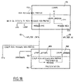
- FIG. 18 represents the exchanges between the body of an application (170) and the presentation (184) of this application, in the case of a message requiring no response and for a presentation implemented on the same entity, such as for example the service processor holding.
- the message (1801) calls on a sending primitive (1810), which after formatting and preparing the message with the necessary headers, sends a DDE message (182) consisting of the address to which the prepared message is stored.
- the message exchange module (183) attached to the presentation when it receives the DDE message, will read the message at the address indicated and launch the message processing operation in the presentation program .
- This message processing operation consists in fetching at the appropriate addresses, the data corresponding to the displays to be carried out, so as to allow the display of a window such as that of FIG. 14.
- the presentation module (184) activates the primitive (1832) which consists in sending an acknowledgment to the attention of the body of the application (180).
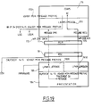
- the operating principle is the same as that of FIG. 18, with the only difference that the dynamic data exchange message (192) is sent to the attention of the RLH program.
- This RLH (11) program interfaces with a second RSC (50) or RMS (60) program located on the remote console.
- the RSC program (50) notifies, upon receipt of a message by the telecommunications line, the XMS application (183) for processing the message of the presentation which is in the waiting state, and transmits this message to the presentation application (184).
- the architecture thus produced makes it possible not only to have a second service processor or a remote station execute the presentation of an application whose body program is executed remotely by a first service processor, but also to improve the Human Machine Interface.
- the RPB card replacement presentation program comprises a first step, represented in FIG. 20, consisting in displaying in a window (2010) a box (20100) showing the various constituent elements of the system: the service processor AUSP (20101), the system cabinet (20102) containing the central subsystem (20104), the power supply (20103) and the ventilation assembly (20103).
- the presentation program brings up a second box (2011), presenting for example in the case of the selection of the central subsystem (20104), all of the cards (20114) available on the front panel and all of the cards (20115) available on the rear panel of the cabinet.
- the program displays a message box (2012) asking to select the location in which you want to replace the card.
- FIG. 12 can also be replaced by a presentation of the type of FIG. 20, with in the message box, a message asking to indicate which location to use to copy the memory.
Landscapes
- Engineering & Computer Science (AREA)
- Theoretical Computer Science (AREA)
- General Engineering & Computer Science (AREA)
- General Physics & Mathematics (AREA)
- Physics & Mathematics (AREA)
- Quality & Reliability (AREA)
- Computer Hardware Design (AREA)
- Information Transfer Between Computers (AREA)
- Computer And Data Communications (AREA)
- Auxiliary Devices For And Details Of Packaging Control (AREA)
- Stored Programmes (AREA)
- Multi Processors (AREA)
- Input From Keyboards Or The Like (AREA)
- Digital Computer Display Output (AREA)
- Exchange Systems With Centralized Control (AREA)
Abstract
Description
La présente invention concerne un dispositif et l'utilisation de ce dispositif dans un procédé de remplacement de cartes.
Il est connu par exemple par la demande de brevet Européen 0 031 782 un dispositif comportant un processeur de service relié par un réseau et une unité de maintenance des canaux reliée à un système central, ledit processeur de service étant relié par un commutateur de console de service à une console éloignée de service.The present invention relates to a device and the use of this device in a card replacement method.
It is known for example from
Par ailleurs, il est également connu dans les systèmes d'effectuer de la télémaintenance ou du téléchargement de programme, à partir d'unités éloignées.Furthermore, it is also known in systems to perform remote maintenance or program download, from remote units.
En général, cette télémaintenance ou ces programmes opérés à distance s'effectuent avec des moyens présentant une ergonomie peu sophistiquée et nécessitant, de la part de l'opérateur, des connaissances spécifiques au système.In general, this remote maintenance or these programs operated remotely are carried out with means having an unsophisticated ergonomics and requiring, on the part of the operator, specific knowledge of the system.
Un premier but de l'invention est donc de proposer un dispositif permettant une utilisation d'un processeur de service d'un système central avec une bonne ergonomie, cette utilisation se faisant éventuellement à distance.A first object of the invention is therefore to propose a device allowing the use of a service processor of a central system with good ergonomics, this use possibly being done remotely.
Ce but est atteint par le fait que le dispositif permet de piloter une application à distance, comportant un premier processeur de service relié par un réseau et une unité de maintenance des canaux reliée à un système central, ledit processeur de service étant relié par un commutateur de console de service, à une console de service de maintenance RMS, et à une console éloignée de service RSC, est caractérisée en ce que le processeur de service et chaque console comportent en plus des programmes de système d'exploitation, un programme superviseur et au moins un service décomposé en deux applications, l'une "corps" composée de l'algorithme du programme, l'autre "présentation" comportant l'interface avec l'opérateur permettant un affichage du type à fenêtres avec une barre de menu, le programme corps de l'application comporte un module bibliothèque d'échange de messages (171) lié au programme corps de l'application et contenant des primitives destinées à émettre ou à recevoir des messages et le programme présentation de l'application comporte des fenêtres générées en fonction de l'application et stockées dans une mémoire, et un module bibliothèque d'échange de messages (183) lié au programme présentation de l'application et contenant des primitives destinées à recevoir ou à émettre des messages, les messages reçus par le module bibliothèque d'échange de messages lié au programme présentation contiennent l'adresse du bloc mémoire dans laquelle le message est stocké et les messages émis contiennent chacun l'adresse du bloc mémoire du programme corps contenant la commande correspondant à la réponse fournie par l'opérateur au message reçu, les messages émis par le module bibliothèque d'échange de messages lié au programme corps de l'application contiennent chacun l'adresse du bloc mémoire contenant le message, et les messages reçus contiennent chacun l'adresse du bloc mémoire du programme corps dans laquelle la réponse fournie par l'opérateur est stockée.This object is achieved by the fact that the device makes it possible to control an application remotely, comprising a first service processor connected by a network and a channel maintenance unit connected to a central system, said service processor being connected by a switch of a service console, to an RMS maintenance service console, and to a remote RSC service console, is characterized in that the service processor and each console additionally comprise operating system programs, a supervisor program and at least one service broken down into two applications, one "body" composed of the program algorithm, the other "presentation" comprising the interface with the operator allowing display of the window type with a menu bar, the application body program comprises a message exchange library module (171) linked to the application body program and containing primitives intended to emit re or to receive messages and the application presentation program comprises windows generated according to the application and stored in a memory, and a message exchange library module (183) linked to the application presentation program and containing primitives intended to receive or transmit messages, the messages received by the message exchange library module linked to the presentation program contain the address of the memory block in which the message is stored and the messages sent each contain the address of the memory block of the body program containing the corresponding command to the response provided by the operator to the message received, the messages sent by the message exchange library module linked to the body program of the application each contain the address of the memory block containing the message, and the messages received each contain the address of the memory block of the body program in which the response provided by the operator is stored.
Une caractéristique supplémentaire de l'invention est de permettre l'utilisation du processeur de réserve pour présenter un service qui est exécuté par le processeur tenant.An additional feature of the invention is to allow the use of the standby processor to present a service which is executed by the holding processor.
selon cette caractéristique le processeur de service de réserve comporte des moyens de faire tourner l'application présentation correspondant à un service, et des moyens de communiquer avec le processeur de service tenant comportant les moyens de faire tourner en même temps l'application tronc d'un service, dont la présentation est faite sur le processeur de réserve, et l'application tronc, ainsi que la présentation d'un deuxième service dont la présentation, est faite sur lui-même.according to this characteristic, the standby service processor comprises means for running the presentation application corresponding to a service, and means for communicating with the holding service processor comprising the means for running the trunk application at the same time a service, the presentation of which is made on the standby processor, and the trunk application, as well as the presentation of a second service, the presentation of which is made on itself.
Selon une autre caractéristique, chaque processeur de service ou console comporte un programme superviseur gérant les numéros d'instance des services, et assurant le démarrage des services.According to another characteristic, each service processor or console comprises a supervisor program managing the instance numbers of the services, and ensuring the starting of the services.
Selon une autre caractéristique, chaque processeur de service comporte des moyens de traitement des communications avec l'autre processeur de service.According to another characteristic, each service processor comprises means for processing communications with the other service processor.
Selon une autre caractéristique, chaque console comporte des moyens de traitement des communications par le commutateur de console de service avec l'un des processeurs de service.According to another characteristic, each console comprises means for processing communications by the service console switch with one of the service processors.
Un autre but de l'invention est de proposer une utilisation du dispositif précédent dans un procédé de remplacement de cartes dans le dispositif, comportant un premier processeur de service relié par un réseau et une unité de maintenance des canaux reliée à un système central, ledit processeur de service étant relié par un commutateur de console de service, à une console de service de maintenance RMS, et à une console éloignée de service RSC, chaque processeur de service et chaque console comportant en plus des programmes de système d'exploitation, un programme superviseur et au moins un service décomposé en deux applications, l'une "corps" composée de l'algorithme du programme, l'autre "présentation" comportant l'interface avec l'opérateur permettant un affichage du type à fenêtres avec une barre de menu, le programme corps de l'application comportant un module bibliothèque d'échange de messages lié au programme corps de l'application et contenant des primitives destinées à émettre ou à recevoir des messages et le programme présentation de l'application comportant des fenêtres générées en fonction de l'application et stockées dans une mémoire, et un module bibliothèque d'échange de messages lié au programme présentation de l'application et contenant des primitives destinées à recevoir ou à émettre des messages , les messages reçus par le module bibliothèque d'échange de message(183) lié au programme présentation contenant chacun l'adresse du bloc mémoire dans laquelle le message est stocké et les messages émis contenant chacun l'adresse du bloc mémoire du programme corps qui contient la commande correspondant à la réponse fournie par l'opérateur au message reçu, les messages émis par le module bibliothèque d'échange de message (173) lié au programme corps de l'application contenant chacun l'adresse du bloc mémoire qui contient le message, et les messages reçus contenant chacun l'adresse du bloc mémoire du programme corps dans laquelle la réponse fournie par l'opérateur est stockée, le service de remplacement de cartes comportant une application de présentation consistant à afficher dans une boîte de dialogue l'identité d'un groupe d'éléments à sélectionner;
- à sélectionner l'identité du groupe d'éléments en validant, par la souris ou le clavier, l'identité ; à sélectionner dans le groupe un des éléments en amenant une surbrillance sur cet élément ;
- à valider la sélection en cliquant avec la souris le pavé contenant le message "OK".
- selecting the identity of the group of elements by validating the identity with the mouse or the keyboard; selecting from the group one of the elements by highlighting this element;
- to validate the selection by clicking with the mouse on the block containing the message "OK".
Selon une autre caractéristique, l'application de la présentation consiste en outre à afficher dans une boîte de dialogue un message indiquant que l'emplacement est occupé, et que le système va essayer de copier son contenu, et une question demandant la confirmation ou l'arrêt du service et à sélectionner la confirmation ou l'arrêt du service, en venant cliquer le pavé correspondant.According to another characteristic, the application of the presentation also consists of displaying in a dialog box a message indicating that the location is occupied, and that the system will try to copy its content, and a question asking for confirmation or stopping the service and to select confirmation or stopping the service, coming click the corresponding block.
Selon une autre particularité, le procédé consiste à afficher dans une boîte de dialogue le groupe d'éléments dans lequel on va sélectionner un deuxième élément en amenant une surbrillance sur cet élément ;
à valider la sélection en cliquant le pavé contenant le message "OK".According to another particularity, the method consists in displaying in a dialog box the group of elements in which a second element will be selected by bringing a highlighting on this element;
to validate the selection by clicking on the block containing the message "OK".
Selon une autre particularité, le procédé consiste à demander confirmation de la demande d'insertion d'une nouvelle carte ;
- à indiquer dans une boîte de dialogue que l'opérateur peut effectuer le changement, et après celui-ci à demander la confirmation ou l'infirmation ;
- à confirmer ou à infirmer l'emplacement en venant cliquer un emplacement indiquant que le second emplacement est plein, respectivement vide.
- to indicate in a dialog box that the operator can make the change, and after this to request confirmation or invalidation;
- to confirm or deny the location by clicking on a location indicating that the second location is full, respectively empty.
Selon une autre particularité, le procédé de l'application présentation consiste à afficher dans une boîte de dialogue l'exécution du test sur la carte mise en place ;
- à afficher la réussite de la copie des informations contenues dans le premier élément ;
- et un message d'autorisation de retrait de la carte du premier emplacement ;
- à demander à l'opérateur, la confirmation ou l'infirmation du retrait en venant cliquer une zone indiquant que le premier emplacement est vide, respectivement occupé.
- display the successful copying of the information contained in the first element;
- and an authorization message for removing the card from the first location;
- to ask the operator for confirmation or cancellation of the withdrawal by clicking on an area indicating that the first location is empty, respectively occupied.
Selon une autre caractéristique de l'invention le programme de présentation a été développé à partir d'un jeu de quatre composants constitués:
- d'un élément noyau qui assure le traitement des tâches ,les allocations mémoires la fonction timer et les liens dynamiques;
- d'un composant utilisateur qui assure le traitement des fenêtres et leur création;
- d'un troisième composant pour réaliser les fonctions graphiques et les dessins;
- d'un quatrième composant qui assure les fonctions de communications synchrones.
- a kernel element which handles the processing of tasks, memory allocations, the timer function and dynamic links;
- a user component which handles the processing of windows and their creation;
- a third component for carrying out the graphic functions and the drawings;
- a fourth component which performs synchronous communications functions.
Un autre but de l'invention est de proposer un procédé d'utilisation sur un dispositif de traitement d'information d'un programme divisé en deux applications.Another object of the invention is to propose a method of using a program divided into two applications on an information processing device.
Ce but est atteint par le fait que le procédé d'utilisation sur un dispositif de traitement d'information comportant au moins un processeur constituant l'unité de traitement exécutant l'algorithme d'un programme d'application et une console, le procédé étant caractérisé en ce que ledit programme d'application est divisé en deux applications, une première application appelée « corps » comportant l'algorithme du programme l'autre application appelée « présentation » comportant l'interface avec l'utilisateur, ladite interface permettant un affichage de type « window » avec une barre de menu ,le programme de présentation et le programme corps comportant chacun un module bibliothèque d'échange de message, le procédé comportant les étapes suivantes:
- stockage du message envoyé par le programme corps dans une mémoire tampon de l'unité de traitement assignée au programme corps et envoi d'un message dynamique d'échange de données à destination du programme de présentation, ledit message dynamique d'échange de données contenant l'adresse du bloc mémoire qui contient le message envoyé par le programme corps;
- réception du message dynamique d'échange de données par le programme présentation et lecture du message stocké à l'adresse indiquée dans le message dynamique d'échange de données;
- traitement du message et affichage du message à l'utilisateur, la réception de la réponse étant traitée par une primitive du module de bibliothèque de message d'échange du programme présentation;
- envoi au programme corps d'un message dynamique accusant la réception du message et envoi d'un second message contenant l'adresse à laquelle la réponse donnée par l'utilisateur a été stockée pour permettre aux primitives de transmission de message et de réception du programme corps d'effectuer le traitement de la réponse par lecture de la réponse contenue à l'adresse indiquée par le message.
- storage of the message sent by the body program in a buffer memory of the processing unit assigned to the body program and sending of a dynamic data exchange message intended for the presentation program, said dynamic data exchange message containing the address of the memory block which contains the message sent by the body program;
- reception of the dynamic data exchange message by the presentation and reading program of the message stored at the address indicated in the dynamic data exchange message;
- processing the message and displaying the message to the user, the reception of the response being processed by a primitive of the exchange message library module of the presentation program;
- sending to the body program of a dynamic message acknowledging receipt of the message and sending of a second message containing the address to which the response given by the user has been stored to allow the message transmission and reception primitives of the program body to process the response by reading the response contained at the address indicated by the message.
Selon une autre caractéristique le procédé d'utilisation sur un dispositif de traitement d'information comportant au moins un processeur constituant l'unité de traitement exécutant l'algorithme d'un programme d'application et une console, le procédé étant caractérisé en ce que ledit programme d'application est divisé en deux applications, une première application appelée « corps » comportant l'algorithme du programme l'autre application appelée « présentation » comportant l'interface avec l'utilisateur, ladite interface permettant un affichage de type « window » avec une barre de menu ,le programme de présentation et le programme corps comportant chacun un module bibliothèque d'échange de message, le procédé comportant les étapes suivantes:
- stockage du message envoyé par le programme corps dans une mémoire tampon de l'unité de traitement assignée au programme corps et envoi d'un message dynamique d'échange de données au programme de présentation , ledit message dynamique d'échange de données contenant l'adresse du bloc mémoire qui contient le message envoyé par le programme corps;
- réception du message dynamique d'échange de données par le programme présentation et lecture du message stocké à l'adresse indiquée dans le message dynamique d'échange de données;
- traitement du message par utilisation des composants du dispositif permettant l'exécution de l'affichage demandé, en cherchant à l'adresse les données correspondant à 1' affichage à effectuer;
- storage of the message sent by the body program in a buffer of the processing unit assigned to the body program and sending of a dynamic data exchange message to the presentation program, said dynamic data exchange message containing the address of the memory block which contains the message sent by the body program;
- reception of the dynamic data exchange message by the presentation and reading program of the message stored at the address indicated in the dynamic data exchange message;
- processing of the message by using the components of the device allowing the execution of the requested display, by looking at the address for the data corresponding to the display to be made;
D'autres caractéristiques et avantages apparaîtront à la lecture de la description ci-après faite en référence aux dessins annexés, dans lesquels :
- la figure 1 représente un schéma d'ensemble du système;
- la figure 2 représente les moyens matériels et de logiciel mettant en communication certaines parties du système ;
- la figure 3 représente le principe du dispositif de l'invention ;
- la figure 4 représente le schéma d'utilisation du principe de l'invention dans une communication entre un processeur de service et des stations éloignées ;
- la figure 5 représente le schéma de principe d'utilisation de l'invention dans le cas d'un processeur de service et d'une seule station éloignée ;
- la figure 6 représente le schéma de principe d'utilisation de l'invention dans le cas d'un processeur de service tenant et d'un processeur de service de réserve ;
- la figure 7 représente les formats des textes de message ;
- la figure 8 représente l'organigramme synoptique du déroulement du programme de remplacement de carte formant le corps du programme ;
- les figures 9 à 16 représentent les différentes étapes du programme de présentation du remplacement d'une carte;
- la figure 17 représente un synoptique des échanges de messages entre le body/corps d'une application et la présentation de cette application dans le cas d'une présentation effectuée sur le même matériel pour un message question/réponse ;
- la figure 18 représente le schéma du synoptique des échanges effectués entre le corps d'une application et la présentation dans le cas d'un message non préfixé ne nécessitant aucune réponse ;
- la figure 19 représente les échanges effectués entre le corps d'une application et la présentation de l'application dans le cas d'une présentation mise en oeuvre à distance de l'application, pour des messages ne nécessitant pas de réponse.
- Figure 1 shows an overall diagram of the system;
- FIG. 2 represents the hardware and software means connecting certain parts of the system;
- Figure 3 shows the principle of the device of the invention;
- FIG. 4 shows the diagram for using the principle of the invention in communication between a service processor and remote stations;
- FIG. 5 represents the diagram of the principle of use of the invention in the case of a service processor and of a single remote station;
- FIG. 6 represents the principle diagram of use of the invention in the case of a service processor holding and a reserve service processor;
- Figure 7 shows the formats of message texts;
- FIG. 8 represents the block diagram of the progress of the card replacement program forming the body of the program;
- Figures 9 to 16 show the different stages of the presentation program for replacing a card;
- FIG. 17 represents a block diagram of the exchanges of messages between the body / body of an application and the presentation of this application in the case of a presentation carried out on the same hardware for a question / answer message;
- FIG. 18 represents the block diagram of the exchanges carried out between the body of an application and the presentation in the case of a non-prefixed message requiring no response;
- FIG. 19 represents the exchanges carried out between the body of an application and the presentation of the application in the case of a presentation works remotely from the application, for messages that do not require a response.
La figure 20 représente une variante de représentation d'une des étapes du programme de présentation de remplacement d'une carte correspondant aux figures 9 ou 12.FIG. 20 represents a variant representation of one of the steps of the presentation program for replacing a card corresponding to FIGS. 9 or 12.
L'architecture du système est constituée, comme représenté à la figure 1, par un processeur de service tenant (1), relié par un logiciel d'interface (10) MSH (Maintenance Station Handler) avec une ligne de traitement de la maintenance des stations de télécommunication (12) formant un réseau de type STARLAN. Cette ligne (12) est reliée à une unité d'horloge et de maintenance (40) qui assure les communications entre le processeur de service (1), un deuxième processeur de service de réserve, par l'intermédiaire d'une deuxième ligne (22), et un système central (41). L'unité de maintenance et d'horloge (40) d'un sous système central (4) communique également par une ligne (43) avec un ensemble de processeurs de maintenance (42). Le processeur de service tenant (1) et le processeur de service de réserve (2) communiquent également par l'intermédiaire d'une interface de gestion de lignes éloigné (11) RLH (Remote Line Handler), et respectivement (21), avec un commutateur de console de service (3), qui permet par l'intermédiaire d'un circuit (30), et d'une matrice de commutation appropriée, de mettre en communication chacun des processeurs de service avec le réseau de télécommunication d'un pays donné, et à travers ce réseau avec une station (5) constituant une console de service éloignée communiquant avec ce réseau (52) par l'intermédiaire d'un logiciel d'interface RSC (50). De même, chacun des processeurs de service peut être mis en communication, à travers le réseau (52), avec une station de maintenance éloignée (6) communiquant avec le réseau (52) par un logiciel d'interface RMS (51). Les lignes (23) et (13) reliées au commutateur de console de service par les logiciels d'interface (21) et (11) ont des débits de 4.800 bauds, tandis que les lignes (12) et (22) formant le réseau STARLAN avec l'unité d'horloge et de maintenance (40) ont des débits de l'ordre du mégabit par seconde. Les processeurs de maintenance (42) sont reliés à des ensembles d'unités d'entrée-sortie pour le système central.The architecture of the system is constituted, as shown in FIG. 1, by a service processor holding (1), connected by an interface software (10) MSH (Maintenance Station Handler) with a line for processing maintenance of the telecommunication stations (12) forming a STARLAN type network. This line (12) is connected to a clock and maintenance unit (40) which ensures communications between the service processor (1), a second standby service processor, via a second line ( 22), and a central system (41). The maintenance and clock unit (40) of a central subsystem (4) also communicates by a line (43) with a set of maintenance processors (42). The service processor holding (1) and the service processor standby (2) also communicate via a remote line management interface (11) RLH (Remote Line Handler), and respectively (21), with a service console switch (3), which makes it possible, via a circuit (30), and an appropriate switching matrix, to activate communication each of the service processors with the telecommunication network of a given country, and through this network with a station (5) constituting a remote service console communicating with this network (52) via software 'RSC interface (50). Likewise, each of the service processors can be put in communication, through the network (52), with a remote maintenance station (6) communicating with the network (52) by an RMS interface software (51). The lines (23) and (13) connected to the service console switch by the interface software (21) and (11) have bit rates of 4,800 baud, while the lines (12) and (22) form the network STARLAN with the clock and maintenance unit (40) have speeds of the order of megabits per second. The maintenance processors (42) are connected to sets of input-output units for the central system.
La figure 2 représente l'environnement logiciel permettant aux processeurs de service (1, 2) de communiquer par le réseau STARLAN avec l'unité de maintenance (40). Le processeur de service tenant comporte en plus du logiciel MSH (10) et d'un système d'exploitation comportant le système d'exploitation du disque MS-DOS, un logiciel multitâches à fenêtre tel que WINDOWS, et une partie de logiciel que l'on décrira ultérieurement. Le processeur de service tenant comporte également un logiciel de communication NETBIOS (100) communiquant à travers une carte de réseau type STARLAN (14) et un élément de hardware (101) constituant une passerelle, à travers la ligne (12) du réseau STARLAN, vers une deuxième passerelle (400), un circuit de gestion (401), un logiciel d'interface NETBIOS (402) et un logiciel d'interface avec le processeur de service (403). De façon similaire, le processeur de service de réserve (2) comportera également les mêmes éléments, mais avec le chiffre 2 comme référence pour le chiffre des dizaines ou des centaines. Chaque processeur de service comporte en plus dans son système d'exploitation (15, 25) un programme corps pour une application donnée (17, 27, fig. 1) et un programme présentation de l'application (18, 28, fig. 1). De même, les consoles éloignées (5, 6) peuvent être constituées, comme pour les processeurs de service, de micro-ordinateurs disposant en plus du clavier d'une souris, et d'un système d'exploitation (65, 55) constitué également comme pour les processeurs de service du système d'exploitation des disques MS-DOS, d'un logiciel multifenêtre WINDOWS, et d'un logiciel superviseur SPV, dont le rôle est de lancer les présentations dans la ou les consoles. Un module LPXMS permet de stocker dans les fichiers LOG et LOGM du disque dur respectivement les messages d'incidents et tous les dialogues de tous les services. Le superviseur du processeur de service tenant connaît également par RLH, l'état de connexion ou de déconnexion des consoles pour commander en conséquence le commutateur de console (30) et configurer les présentations, comme nous le verrons ultérieurement. De même, l'unité de maintenance et d'horloge permet de lancer le deuxième processeur de service en cas de défaillance du premier, et le superviseur SPV instaure dans ce dernier les mêmes applications. Ces stations éloignées (5, 6) comportent également des logiciels de présentation (58, 68) correspondant aux logiciels de présentation des programmes corps d'une application tournant sur un processeur de service (1), respectivement (2).FIG. 2 represents the software environment allowing the service processors (1, 2) to communicate via the STARLAN network with the maintenance unit (40). The service processor holding comprises in addition to the MSH software (10) and an operating system comprising the operating system of the MS-DOS disk, multitasking window software such as WINDOWS, and a part of software that the 'will be described later. The service processor holding also includes NETBIOS communication software (100) communicating through a network card STARLAN type (14) and a hardware element (101) constituting a gateway, through the line (12) of the STARLAN network, to a second gateway (400), a management circuit (401), NETBIOS interface software (402) and software for interfacing with the service processor (403). Similarly, the standby service processor (2) will also have the same elements, but with the
La figure 3 représente le principe de l'architecture nécessaire à la mise en oeuvre de l'invention dans laquelle le programme corps (17) d'une application donnée, tournant par exemple sur le processeur de service tenant, échange des lignes de texte et des messages d'acquittement ou de réponse avec le programme de présentation (18) de l'application. Ces échanges de messages et de lignes de texte se font par l'intermédiaire de modules de bibliothèque de gestion des messages LBXMS (171) et LPXMS (183) qui se trouvent liés respectivement au corps de l'application et à la présentation de l'application. Le programme de présentation de l'application échange avec le logiciel WINDOWS (150), les primitives nécessaires à la gestion des tâches et à l'affichage des fenêtres. L'application présentation aura été développée à l'aide du programme WINDOWS (150) qui peut être vu comme un jeu de quatre composants. Un premier composant noyau (Kernel) (151) assurant la gestion des tâches, les allocations de mémoire, la fonction TIMER et les liens dynamiques. Un deuxième élément (152) utilisateur (user) servant à assurer la gestion des fenêtres et la création de celles-ci. Un troisième élément GDI (153) permettant de réaliser les fonctions graphiques en vue d'effectuer des dessins, et un quatrième élément (154) COM assurant les fonctions de communication de manière asynchrone, par exemple au moyen d'un protocole DDE (échange dynamique de données) qui est un protocole d'échange de données entre applications et permet la communication entre applications.FIG. 3 represents the principle of the architecture necessary for the implementation of the invention in which the body program (17) of a given application, running for example on the service processor holding, exchanging lines of text and acknowledgment or response messages with the presentation program (18) of the application. These exchanges of messages and lines of text are carried out by means of library management modules for messages LBXMS (171) and LPXMS (183) which are linked respectively to the body of the application and to the presentation of the application. The presentation program of the application exchanges with the WINDOWS software (150), the primitives necessary for the management of tasks and the display of windows. The presentation application will have been developed using the WINDOWS (150) program which can be seen as a set of four components. A first kernel component (Kernel) (151) ensuring the management of tasks, allocations of memory, TIMER function and dynamic links. A second user element (152) used to manage the windows and create them. A third GDI element (153) making it possible to carry out the graphic functions for drawing purposes, and a fourth COM element (154) ensuring the communication functions asynchronously, for example by means of a DDE protocol (dynamic exchange which is a data exchange protocol between applications and allows communication between applications.
La communication avec des lignes de texte permet de réduire la densité des informations par rapport à une communication constituée par un jeu de primitives WINDOWS, qui sont utilisées pour générer un écran, et par conséquent, accélère les échanges.Communication with lines of text makes it possible to reduce the density of information compared to a communication constituted by a set of WINDOWS primitives, which are used to generate a screen, and consequently, accelerates exchanges.
La figure 4 représente le fonctionnement de l'architecture dans le cas d'un processeur de service tenant (1) connecté par l'intermédiaire d'un commutateur de console de service (30) à la console de maintenance éloignée (6) et à la console de service éloignée (5) constituée par un micro-ordinateur. Ce micro-ordinateur, comme le processeur de service (1), comporte une souris et un système d'exploitation (550, 551, 552) constitué respectivement par le logiciel MS-DOS, WINDOWS et un superviseur SPV. Pour la station de maintenance, le système d'exploitation est constitué de la même façon par les éléments (650, 651, 652). Une interface RSC (50) assure l'interface entre les lignes de télécommunication et le micro-ordinateur (5), et à travers ces lignes de télécommunication, vers le processeur de service qui se trouve lui-même interfacé avec les lignes de communication par l'interface RLH (11). De même, la station de maintenance comporte une interface RMS (60) ayant les mêmes fonctions que l'interface RSC. Cette interface RSC communique par un module bibliothèque de messages (583) lié à la présentation de l'application (58) constituée par une application RPB de remplacement de carte (replace board). Le corps de l'application (17) de remplacement de carte tourne sur le processeur de service tenant et se trouve lié à une bibliothèque de messages permettant la communication avec l'interface RLH (11). Le commutateur de console de service (30) permet, grâce à une matrice de commutation et aux informations fournies par l'interface RLH du processeur tenant (1), d'acheminer directement les messages provenant du processeur de service vers les deux consoles, si ces deux consoles sont branchées, d'acheminer tous les messages émis par la console de service éloignée (5) vers le processeur de service (1) et la console de maintenance, si celle-ci est branchée, et d'acheminer tous les messages émis par la console de maintenance vers le processeur de service. Ceci est permis par le fait que RLH, au fur et à mesure des connexions des consoles, établit un dialogue avec l'interface RSC ou RMS respective, et notifie au programme superviseur (152) l'état de connexion ou de déconnexion des consoles du réseau. Cette table sert ensuite à établir les communications à travers le commutateur de console (30).FIG. 4 represents the operation of the architecture in the case of a service processor holding (1) connected via a service console switch (30) to the remote maintenance console (6) and to the remote service console (5) consisting of a microcomputer. This microcomputer, like the service processor (1), comprises a mouse and an operating system (550, 551, 552) constituted respectively by the software MS-DOS, WINDOWS and a supervisor SPV. For the maintenance station, the operating system is constituted in the same way by the elements (650, 651, 652). An RSC interface (50) provides the interface between the telecommunication lines and the microcomputer (5), and through these telecommunication lines, to the service processor which is itself interfaced with the communication lines by the RLH interface (11). Likewise, the maintenance station includes an RMS interface (60) having the same functions as the RSC interface. This RSC interface communicates by a message library module (583) linked to the presentation of the application (58) constituted by a RPB card replacement application (replace board). The body of the card replacement application (17) rotates on the holding service processor and is linked to a message library allowing communication with the RLH interface (11). The service console switch (30) makes it possible, thanks to a switching matrix and to the information provided by the RLH interface of the holding processor (1), to direct messages coming from the service processor to the two consoles, if these two consoles are connected, to route all the messages sent by the remote service console (5) to the service processor (1) and the maintenance console, if the latter is connected, and to route all the messages issued by the maintenance console to the service processor. This is enabled by the fact that RLH, as the consoles are connected, establishes a dialogue with the respective RSC or RMS interface, and notifies the supervisor program (152) the state of connection or disconnection of the consoles from the network. This table is then used to establish communications through the console switch (30).
La figure 5 représente le fonctionnement de l'architecture décrite dans le cas où le processeur de service (1) est en communication avec une console éloignée (5). Cette console éloignée (5) servant à effectuer la présentation d'une application RPB (58), grâce au module de bibliothèque XMESS (583) et à l'interface RSC (50) qui communique par le réseau avec l'interface RLH (11) du processeur de service. Dans cette communication, le processeur de service exécute le programme corps de l'application (17), et le superviseur (152) stocke, sur un disque (16), dans un fichier LOG (160) et dans un fichier LOGM (161), respectivement les messages d'incidents et tous les dialogues de tous les services tournant dans le processeur de service.FIG. 5 represents the operation of the architecture described in the case where the service processor (1) is in communication with a remote console (5). This remote console (5) used to present a RPB application (58), thanks to the XMESS library module (583) and to the RSC interface (50) which communicates via the network with the RLH interface (11 ) of the service processor. In this communication, the service processor executes the application body program (17), and the supervisor (152) stores, on a disk (16), in a LOG file (160) and in a LOGM file (161) , respectively the incident messages and all the dialogs of all the services running in the service processor.
L'interface RLH (11) voit les stations éloignées à travers le commutateur de console de service (30) et conduit seulement une ligne de communication de données reliant RLH et SCC. Les deux lignes de communication de données, liant le processeur de service avec les stations RMS et RSC, sont conduites par SCC.The RLH interface (11) sees the remote stations through the service console switch (30) and conducts only one data communication line connecting RLH and SCC. The two data communication lines, linking the service processor with the RMS and RSC stations, are conducted by SCC.
Dans l'architecture de la figure 5, le processeur de service (1) peut, par exemple, exécuter une autre application appelée VMP, et grâce au programme de présentation de cette application VMP, présenter cette application sur son moniteur, tandis que la deuxième application RPB sera présentée sur le moniteur de la station RSC. En même temps, une copie de dialogue de l'application VMP sera disponible sur la station RSC.In the architecture of FIG. 5, the service processor (1) can, for example, execute another application called VMP, and thanks to the presentation program of this VMP application, present this application on its monitor, while the second RPB application will be presented on the monitor of the RSC station. At the same time, a dialog copy of the VMP application will be available on the RSC station.
La figure 6 représente un autre avantage de l'architecture proposée qui permet, par exemple, d'utiliser le processeur de service de réserve (2) pour effectuer la présentation d'une application qui tourne sur le processeur de service tenant (1). Ceci présente l'avantage de permettre une utilisation du processeur de service de réserve qui, compte tenu de l'augmentation de la fiabilité des matériels, devient de moins en moins sollicité dans son rôle de processeur de service de réserve, et peut ainsi être utilisé comme console complémentaire de présentation d'une application.FIG. 6 represents another advantage of the proposed architecture which makes it possible, for example, to use the standby service processor (2) to make the presentation of an application which is running on the holding service processor (1). This has the advantage of allowing use of the standby service processor which, given the increase in the reliability of the hardware, becomes less and less used in its role as standby service processor, and can thus be used. as an additional console for presenting an application.
Dans le cas de la figure 6, le processeur de service (2) exécute la présentation de l'application RPB (28), tandis que le corps de l'application RPB est exécuté par le processeur de service tenant (1). Les processeurs de service (1) et (2) communiquent entre eux par les interfaces MSH (10, 20) et le réseau STARLAN, comme représenté à la figure 2.In the case of FIG. 6, the service processor (2) executes the presentation of the RPB application (28), while the body of the RPB application is executed by the service processor holding (1). The service processors (1) and (2) communicate with each other via the MSH interfaces (10, 20) and the STARLAN network, as shown in FIG. 2.
La figure 7 représente le format des messages. Le premier type de format correspond aux messages échangés entre le corps d'une application et le module bibliothèque XMESS. Dans ce cas là, le format est constitué d'un numéro de message qui peut être VSH 001, ou RPB 120 dans le cas de l'application de remplacement de carte, suivi du texte du message qui peut être "mon message préfixé", où dans le cas de l'application remplacement de carte, "l'emplacement requis contient une carte".Figure 7 shows the format of the messages. The first type of format corresponds to the messages exchanged between the body of an application and the XMESS library module. In this case, the format consists of a message number which can be
Lorsque les messages sont échangés entre les modules de bibliothèque XMESS de deux interfaces éloignés, le message est constitué du nom de service qui peut être SYC 01, de l'instance, suivi du numéro de message et du texte comme vu précédemment. Les messages archivés, représentés à la dernière ligne, font précéder le format du message d'interface XMESS de la date et de l'heure.When the messages are exchanged between the XMESS library modules of two remote interfaces, the message consists of the service name which can be
Les figures 8 à 16 représentent un exemple d'une application dont le corps et la présentation peuvent être séparés selon le principe de l'invention.Figures 8 to 16 show an example of an application whose body and presentation can be separated according to the principle of the invention.
L'algorithme du déroulement du programme corps est représenté par la figure 8, tandis que les figures 10 à 15 représentent les résultats produits par l'exécution de l'application présentation.The algorithm for running the body program is shown in Figure 8, while Figures 10 to 15 show the results produced by the execution of the presentation application.
La génération des différentes fenêtres correspondant aux figures 9 à 16, formant une partie de l'application présentation correspondant au programme de l'application corps du remplacement de carte, ont été générées, par exemple, en utilisant le procédé pour la génération de fenêtres de dialogues visualisables sur l'écran d'un système informatique, et le dispositif pour mettre en oeuvre ce procédé enseigné par la demande de brevet français déposée au nom de BULL S.A. le 22 Juin 1988, sous le numéro 88.08381 correspondant au brevet EP-A-0 348 293.The generation of the different windows corresponding to FIGS. 9 to 16, forming part of the presentation application corresponding to the program of the body replacement application of the card, were generated, by example, using the method for generating dialog windows that can be viewed on the screen of a computer system, and the device for implementing this method taught by the French patent application filed on behalf of BULL SA on June 22, 1988 , under the number 88.08381 corresponding to patent EP-A-0 348 293.
La première étape consiste dans le lancement du service RPB, indiqué par la référence (900). Cette étape consiste d'abord à faire apparaître en fenêtre le service superviseur SPV pour venir sélectionner dans le menu des différents services le remplacement de carte RPB, et le lancer en cliquant sur son nom avec la souris. Une fois le service lancé, la première question que pose RPB est de lui fournir l'identifieur de l'emplacement physique où s'opère la manipulation. Ceci est indiqué par l'étape (901) sur l'organigramme. Cette étape se traduit dans le programme de présentation de remplacement de carte par l'apparition d'une fenêtre (9010, fig. 9) à l'intérieur de laquelle est représentée une boîte de dialogue (9011) comportant un premier ensemble (9012) constitué par une boîte de trois boutons radio, correspondant à chacun des types d'éléments susceptibles d'être remplacés. Le premier (9120) correspondant aux unités centrales de processeur IP, le deuxième (9121) correspondant aux unités mémoire HM, le troisième (9122) correspondant aux unités d'entrée-sortie IU. Cette boîte de dialogue comporte une boîte de listage (9013) qui, une fois que l'on a sélectionné un type d'éléments, par exemple le type des unités mémoire en venant cliquer le bouton radio se trouvant en vis-à-vis, fait apparaître dans la boîte de listage, la liste des différents éléments de l'unité de mémoire susceptibles d'être sélectionnés. Cette liste apparaît par un système de déroulement bien connu des utilisateurs de WINDOWS. Une fois le type d'unité, et l'identité de cette unité sélectionnée, on valide le choix en venant cliquer avec la souris un pavé de validation (9014).The first step is to launch the RPB service, indicated by the reference (900). This step consists first of making the SPV supervisor service appear in the window to come and select from the menu of different services the replacement of the RPB card, and launch it by clicking on its name with the mouse. Once the service is launched, the first question posed by RPB is to provide it with the identifier of the physical location where the manipulation takes place. This is indicated by step (901) on the flow chart. This step is reflected in the card replacement presentation program by the appearance of a window (9010, fig. 9) inside which is represented a dialog box (9011) comprising a first assembly (9012) consisting of a box of three radio buttons, corresponding to each of the types of elements likely to be replaced. The first (9120) corresponding to the central processing units of IP, the second (9121) corresponding to the memory units HM, the third (9122) corresponding to the input-output units IU. This dialog box includes a list box (9013) which, once a type of element has been selected, for example the type of memory units by clicking on the radio button opposite, brings up in the list box, the list of the different elements of the memory unit that can be selected. This list appears by a flow system well known to WINDOWS users. Once the type of unit and the identity of this unit selected, the choice is validated by clicking with the mouse on a validation block (9014).
Après l'étape de détermination d'emplacement (901), le programme corps passe à l'étape de réquisition d'emplacement pour permettre la manipulation désirée. Si l'unité physique présente dans l'emplacement choisi est indisponible, le programme corps provoque dans le programme présentation l'affichage de cette information puis s'interrompt à l'étape (907). L'affichage de cette information d'indisponibilité se traduit entre le programme corps et la présentation par l'échange d'un message référencé "RPB 120" indiquant "l'emplacement requis contient une carte en ce moment". Ce message, traité par le programme présentation, provoque l'apparition de la fenêtre (9050, fig. 10) dans laquelle une boîte de dialogue (9051) contient un élément figuratif et la phrase du message, ainsi qu'un pavé de validation (9052) qui, après avoir été cliqué par la souris, permet d'accuser réception du message, comme représenté avec la figure 17.After the location determination step (901), the body program proceeds to the location requisition step to allow the desired manipulation. If the physical unit present in the chosen location is unavailable, the body program causes the presentation program to display this information and then stops in step (907). The display of this unavailability information is reflected between the body program and the presentation by the exchange of a message referenced "
Une deuxième boîte de dialogue dans cette fenêtre demande à l'opérateur s'il veut avorter cette action, ou la poursuivre. Cette deuxième boîte contient le pavé (9071) qui correspond à l'interruption de l'action et détourne le programme corps sur l'étape "fin" (911, fig. 8). Un deuxième pavé (9072, fig. 10) déclenche, par un message réponse envoyé au programme corps, la poursuite de la manipulation par l'étape de préparation de la manipulation (909, fig. 8) du programme corps.A second dialog box in this window asks the operator if he wants to abort this action, or continue it. This second box contains the block (9071) which corresponds to the interruption of the action and diverts the body program to the "end" stage (911, fig. 8). A second block (9072, fig. 10) triggers, by a response message sent to the body program, the continuation of the manipulation by the manipulation preparation stage (909, fig. 8) of the body program.
Si l'emplacement est libre, ou si l'unité qu'il contient n'est utilisée par aucun service ou système, le programme corps RPB informe la présentation du succès de la réquisition par un message et prépare la manipulation à l'étape (909) en indiquant à l'opérateur que le système essaye de copier la carte non utilisée. Ceci est représenté à la figure 11, par la fenêtre (9090) qui comporte une boîte de dialogue (9091), à l'intérieur de laquelle apparaît un message "la carte mémoire est attribuée, nous essayons de la copier", et un pavé de validation (9092). Cette fenêtre (9090) comporte également une deuxième boîte de dialogue (9110) dans laquelle un premier pavé permet d'interrompre l'action, comme représenté à l'étape (911) de la figure 9, et un deuxième pavé (9112) permet de poursuivre l'action en passant à l'étape (913) de l'organigramme de la figure 9.If the location is free, or if the unit it contains is not used by any service or system, the RPB body program informs the presentation of the success of the requisition by a message and prepares the manipulation for step ( 909) by indicating to the operator that the system is trying to copy the unused card. This is represented in figure 11, by the window (9090) which includes a dialog box (9091), inside which appears a message "the memory card is allocated, we are trying to copy it", and a block validation (9092). This window (9090) also includes a second dialog box (9110) in which a first block makes it possible to interrupt the action, as shown in step (911) of FIG. 9, and a second block (9112) allows to continue the action by going to step (913) of the flow diagram of FIG. 9.
L'étape de détermination de l'emplacement (901) peut éventuellemennt être suivie d'une étape de complément d'informations (904), par exemple dans le cas où l'on veut procéder à la recopie d'une carte mémoire, vers un emplacement de la carte destinée à la recopie. Cette étape déclenche dans le programme présentation, l'affichage de la fenêtre (9040) qui comporte une boîte de dialogue (9041) de constitution identique à la boîte de dialogue (9011).The step of determining the location (901) can optionally be followed by a complementary step information (904), for example in the case where one wishes to copy a memory card to a location on the card intended for copying. This step triggers in the presentation program, the display of the window (9040) which includes a dialog box (9041) of constitution identical to the dialog box (9011).
Dans l'exemple représenté, on va recopier les informations de l'unité mémoire (HM04) vers l'unité mémoire (HM08) dans laquelle on va insérer une carte mémoire. Cette étape (904) se poursuit par une étape dans laquelle on précise si l'opérateur compte utiliser une nouvelle carte, ou une carte en place pour la recopie. Ceci correspond aux étapes (906) ou (908) sur l'organigramme de la figure 8. Ces étapes déclenchent dans le programme de présentation, l'affichage d'une fenêtre (9060, fig. 13A) comportant une boîte de dialogue (9061) portant la question "Avez-vous une nouvelle carte à insérer ?", et un pavé de réponse "Oui" (9062) indiquant qu'il y a une nouvelle carte, et un pavé de réponse "Non" (9080) indiquant que l'on compte utiliser une carte existante. Les pavés sont, de façon connue, validés par la souris du processeur de service ou de la station éloignée utilisée pour faire tourner la présentation.In the example shown, we will copy the information from the memory unit (HM04) to the memory unit (HM08) into which we will insert a memory card. This step (904) continues with a step in which it is specified whether the operator intends to use a new card, or a card in place for copying. This corresponds to steps (906) or (908) on the flow diagram of FIG. 8. These steps trigger in the presentation program, the display of a window (9060, fig. 13A) comprising a dialog box (9061 ) with the question "Do you have a new card to insert?", and a "Yes" answer block (9062) indicating that there is a new card, and a "No" answer block (9080) indicating that we plan to use an existing card. The blocks are, in known manner, validated by the mouse of the service processor or of the remote station used to run the presentation.
Si l'opérateur désire utiliser une carte de l'installation, ce qui en général est un cas exceptionnel, RPB vérifie que l'unité désignée est disponible, et dans l'affirmative la requiert par l'étape (912, fig. 8) qui sera explicitée plus loin. Dans le cas où l'opérateur souhaite utiliser une nouvelle carte, RPB s'assure que l'emplacement désigné est bien vide, et dans l'affirmative, le requiert au cours de l'étape (909) de préparation de la manipulation.If the operator wishes to use a system card, which is generally a case exceptional, RPB checks that the designated unit is available, and if so requires it by step (912, fig. 8) which will be explained below. In the event that the operator wishes to use a new card, RPB ensures that the designated location is indeed empty, and if so, requires it during the step (909) of preparation for handling.
Une fois la manipulation préparée, le programme corps reçoit le feu vert de l'unité centrale, et indique à l'étape "action" (913) que la manipulation peut être effectuée. Cette étape "action" (913) déclenche, au niveau du programme de présentation PRPB, l'affichage de la fenêtre (9130, fig. 13B), laquelle comporte une boîte de dialogue (9131) incluant le message d'autorisation d'insertion de la carte dans l'emplacement défini, et incluant une deuxième boîte de dialogue (9132) demandant d'indiquer, une fois que l'opération est terminée, si l'emplacement est plein ou vide en validant respectivement l'un des deux boutons radio (9150) ou (9170). Ensuite, l'opération est validée en cliquant avec la souris, le pavé (9133).Once the manipulation has been prepared, the body program receives the green light from the central unit, and indicates in the "action" step (913) that the manipulation can be carried out. This “action” step (913) triggers, at the level of the PRPB presentation program, the display of the window (9130, FIG. 13B), which includes a dialog box (9131) including the message of authorization for insertion. of the map in the defined location, and including a second dialog box (9132) asking to indicate, once the operation is finished, whether the location is full or empty by validating one of the two buttons respectively radio (9150) or (9170). Then, the operation is validated by clicking with the mouse, the block (9133).
Dans le cas où l'on effectue un ajout d'une carte, le programme corps se poursuit par l'étape (921) au cours de laquelle un test de la carte en place est effectué avant d'autoriser son insertion définitive dans l'installation. Ces tests seront effectués par le service "DGM" qui va être lancé automatiquement par RPB, et RPB se mettra en attente du résultat. Une fois le résultat du test transmis par DGM à RPB, le programme de présentation de remplacement de carte vous informe du résultat du test. Ceci est effectué par le message RPB (111) "Tout va bien, l'initialisation de la nouvelle carte est réussie" (All right, the new board init is successful). Dans ce cas, le service s'achève à l'étape (907). Dans le cas où la nouvelle carte est invalide, le programme corps RPB vous propose à l'étape (923) un nouvel échange de carte, et si vous l'acceptez, le programme repart à l'étape (909).In the case where an addition of a card is carried out, the body program continues with step (921) during which a test of the card in place is carried out before authorizing its final insertion into the installation. These tests will be carried out by the "DGM" service which will be launched automatically by RPB, and RPB will start waiting for the result. Once the test result has been transmitted by DGM to RPB, the card replacement presentation program informs you of the test result. This is done by the message RPB (111) "All is well, the initialization of the new card is successful" (All right, the new board init is successful). In this case, the service ends at step (907). In the event that the new card is invalid, the RPB body program offers you in step (923) a new card exchange, and if you accept it, the program resumes in step (909).
Dans le cas où l'on souhaitait procéder à un échange et à une recopie de carte mémoire à la fin de l'étape (913), le programme corps RPB nous renvoie sur l'étape (912) de test et d'initialisation. Dans ce cas, la carte mémoire destinée à la recopie ayant été introduite, le programme corps RPB va tenter de l'initialiser. Ceci est indiqué par le programme présentation RPB en affichant la fenêtre (9120) dans laquelle une boîte de dialogue (9121) affiche le message "Test en cours", ainsi qu'un pavé de validation (9122) permettant d'acquitter la réception du message envoyé par le programme corps RPB. Si la nouvelle carte est valide, RPB vérifie qu'elle est bien compatible avec la carte fautive dont elle est sensée prendre la place, et dans le cas affirmatif, RPB effectue la recopie et l'échange, et signale qu'il faut enlever l'ancienne carte dont il rappelle l'identifieur.If we wanted to exchange and recopy a memory card at the end of step (913), the RPB body program returns us to step (912) for testing and initialization. In this case, the memory card intended for copying having been inserted, the RPB body program will attempt to initialize it. This is indicated by the RPB presentation program by displaying the window (9120) in which a dialog box (9121) displays the message "Test in progress", as well as a validation block (9122) allowing to acknowledge receipt of the message sent by the RPB body program. If the new card is valid, RPB checks that it is compatible with the faulty card which it is supposed to take the place of, and in the affirmative case, RPB performs the copying and the exchange, and signals that it is necessary to remove the 'old card which it recalls the identifier.
L'étape d'initialisation est représentée dans la fenêtre (9123, fig. 15.A) par la boîte de dialogue (9124), laquelle contient le message "Tout va bien, la copie est réussie", et un pavé de validation (9125) permettant d'acquitter la réception du message. Après cet affichage et la validation de ce message, le corps RPB envoie un second message informant l'opérateur qu'il peut maintenant retirer la carte. Ce message est affiché dans une boîte de dialogue (9126) et comporte également un pavé de validation (9127) permettant d'acquitter la réception dudit message. Dans le cas où la carte est incompatible, RPB signale qu'il faut la retirer et rappelle son identifieur.The initialization step is represented in the window (9123, fig. 15.A) by the dialog box (9124), which contains the message "Everything is fine, the copy is successful", and a validation block ( 9125) to acknowledge receipt of the message. After this display and validation of this message, the RPB body sends a second message informing the operator that it can now remove the card. This message is displayed in a dialog box (9126) and also includes a validation block (9127) making it possible to acknowledge receipt of said message. In the event that the card is incompatible, RPB indicates that it must be removed and recalls its identifier.
Dans le cas où la carte après le test est jugée invalide, RPB vous propose d'effectuer un nouvel échange, et si vous acceptez cet échange proposé à l'étape (918), le programme vous renvoie à l'étape (909).In the event that the card after the test is found to be invalid, RPB offers to carry out a new exchange, and if you accept this exchange proposed in step (918), the program returns you to step (909).
L'étape de retrait (914) fait apparaître la fenêtre (9140, fig. 15B), laquelle contient une boîte de dialogue (9141) incluant un dessin (9142) et un message (91410) indiquant qu'il faut retirer la carte située dans l'emplacement HM04. Cette boîte de dialogue comporte également une boîte de boutons radio (9143) demandant d'indiquer lorsque l'on a terminé l'opération et permettant par le bouton radio (91430) d'indiquer que l'emplacement est plein, et par le bouton radio (9431) d'indiquer que l'emplacement est vide, et que par conséquent, la carte a bien été retirée. Cette fenêtre de dialogue est validée par un pavé de validation (9144) permettant de valider les réponses cliquées par la souris.The removal step (914) brings up the window (9140, fig. 15B), which contains a dialog box (9141) including a drawing (9142) and a message (91410) indicating that the card located must be removed in location HM04. This dialog box also includes a radio button box (9143) asking to indicate when the operation is finished and allowing the radio button (91430) to indicate that the location is full, and by the button radio (9431) to indicate that the space is empty, and that by Consequently, the card has been successfully removed. This dialog window is validated by a validation block (9144) allowing to validate the responses clicked by the mouse.
Une fois le retrait effectué, le programme provoque, à l'étape (916) l'affichage du message représenté dans la boîte de dialogue (9160, fig. 16), indiquant que la copie a été effectuée normalement et qu'il n'y a pas de problème particulier. L'opérateur acquitte la réception du message en validant le pavé (9161).Once the withdrawal has been made, the program causes, in step (916), the message shown in the dialog box (9160, fig. 16) to be displayed, indicating that the copy has been made normally and that it is there is no particular problem. The operator acknowledges receipt of the message by validating the block (9161).
On a ainsi décrit les différentes étapes du programme corps, ainsi que les affichages effectués par le programme présentation associé à ce programme corps dans une application particulière qui est le remplacement de cartes.We have thus described the different stages of the body program, as well as the displays made by the presentation program associated with this body program in a particular application which is the replacement of cards.
Les affichages de ce programme présentation étant développés à l'aide, par exemple, du procédé décrit dans la demande de brevet français intitulé "Procédé pour la génération de fenêtres de dialogue visualisables sur l'écran d'un système informatique", et les fenêtres ainsi générées, sont stockés dans une mémoire et appelées au fur et à mesure des besoins de l'affichage par les messages générés par le programme corps, comme on l'explique en relation avec les figures 17 à 19 ci-après.The displays of this presentation program being developed using, for example, the method described in the French patent application entitled "Method for the generation of dialog windows viewable on the screen of a computer system", and the windows thus generated, are stored in a memory and called as and when required by the display by the messages generated by the body program, as is explained in relation to FIGS. 17 to 19 below.
La figure 17 représente les échanges entre le corps d'une application (170) et la présentation (184) de cette application, dans le cas d'un message ne nécessitant pas de réponse et pour une présentation mise en oeuvre sur la même entité. Le programme corps de l'application (170) se trouve lié (linked) à un module de bibliothèque d'échange de messages (171). Lorsqu'au cours du déroulement du programme corps (170), celui-ci arrive à une étape de message à émettre ou de question à émettre, représentée par la référence (1701), correspondant dans le cas représenté à une question à préfixe, le programme corps (170) fait appel dans le module de bibliothèque (171) à une primitive d'émission et de réception de message (1710), primitive (send/receive) d'émission/réception. Cette primitive stocke le message à émettre dans une mémoire tampon du processeur de service et émet un message DDE (Dynamic Data Exchange) d'échange dynamique de données (172). Au cours de cette opération, le programme d'échange XMS de messages écrit le message dans le fichier du disque dur LOGM (1711) qui contient le dialogue de tous les services (1711). Le message (172) d'échange dynamique de données, émis par le processeur de service dans lequel tourne le corps de l'application à destination du logiciel de présentation tournant sur le même processeur, contient l'adresse du bloc mémoire qui contient le message ou la question.FIG. 17 represents the exchanges between the body of an application (170) and the presentation (184) of this application, in the case of a message requiring no response and for a presentation implemented on the same entity. The application body program (170) is linked (linked) to a message exchange library module (171). When during the course of the body program (170), the latter arrives at a message to be sent or question to be sent step, represented by the reference (1701), corresponding in the case shown to a question with a prefix, the body program (170) calls in the library module (171) a message sending and receiving primitive (1710), sending / receiving primitive (send / receive). This primitive stores the message to be sent in a buffer of the service processor and sends a DDE (Dynamic Data Exchange) message for dynamic data exchange (172). During this operation, the XMS message exchange program writes the message to the LOGM hard disk file (1711) which contains the dialog of all the services (1711). The message (172) for dynamic data exchange, sent by the service processor in which the body of the application turns to the presentation software running on the same processor, contains the address of the memory block which contains the message or the question.
L'application de présentation et son module d'échange de messages (183) est en état d'attente, représenté par LPXMS_WAIT de l'étape (1830). L'application présentation (184) reçoit un message VM_DDE_DATA (172), puis cette application va lire le message à l'adresse indiquée. Une fois cette lecture effectuée, l'application traite le message en allant chercher dans le programme de présentation de l'application, les éléments permettant d'effectuer les affichages requis et de recevoir les réponses nécessitées par la question. Une fois la réponse fournie par l'opérateur de la console, cette réponse (1840) est délivrée à une primitive de réception (1831) (receiver) du module de bibliothèque d'échange de messages (183). Cette primitive permet d'envoyer un premier message dynamique (175) d'acquittement de la réception de la question, et après mise en forme de la réponse, d'envoyer un message (176) contenant l'adresse mémoire à laquelle la réponse a été stockée, pour permettre à la primitive (1710) d'effectuer le traitement de la réponse en allant lire la réponse contenue à l'adresse indiquée par le message (176).The presentation application and its message exchange module (183) is in the waiting state, represented by LPXMS_WAIT from step (1830). The presentation application (184) receives a VM_DDE_DATA (172) message, then this application will read the message at the address indicated. Once this reading has been done, the application processes the message by going to look in the presentation program of the application, the elements making it possible to carry out the required displays and to receive the answers required by the question. Once the response has been provided by the console operator, this response (1840) is delivered to a reception primitive (1831) (receiver) of the message exchange library module (183). This primitive makes it possible to send a first dynamic message (175) for acknowledging receipt of the question, and after formatting the response, to send a message (176) containing the memory address to which the response has been stored, to allow the primitive (1710) to process the response by going to read the response contained at the address indicated by the message (176).
La figure 18 représente les échanges entre le corps d'une application (170) et la présentation (184) de cette application, dans le cas d'un message ne nécessitant pas de réponse et pour une présentation mise en oeuvre sur la même entité, tel que par exemple le processeur de service tenant. Dans cet exemple, le message (1801) fait appel à une primitive (1810) d'émission, qui après mise en forme et préparation du message avec les entêtes nécessaires, émet un message DDE (182) constitué par l'adresse à laquelle le message préparé est stocké. De façon similaire, le module d'échange de messages (183) rattaché à la présentation, lorsqu'il reçoit le message DDE, va lire le message à l'adresse indiquée et lance l'opération de traitement du message dans le programme de présentation. Cette opération de traitement du message consiste à aller chercher aux adresses adéquates, les données correspondant aux affichages à effectuer, de façon à permettre l'affichage d'une fenêtre telle que celle de la figure 14. Lorsque le traitement du message est effectué, le module présentation (184) active la primitive (1832) qui consiste à émettre un accusé de réception à l'attention du corps de l'application (180).FIG. 18 represents the exchanges between the body of an application (170) and the presentation (184) of this application, in the case of a message requiring no response and for a presentation implemented on the same entity, such as for example the service processor holding. In this example, the message (1801) calls on a sending primitive (1810), which after formatting and preparing the message with the necessary headers, sends a DDE message (182) consisting of the address to which the prepared message is stored. Similarly, the message exchange module (183) attached to the presentation, when it receives the DDE message, will read the message at the address indicated and launch the message processing operation in the presentation program . This message processing operation consists in fetching at the appropriate addresses, the data corresponding to the displays to be carried out, so as to allow the display of a window such as that of FIG. 14. When the processing of the message is carried out, the presentation module (184) activates the primitive (1832) which consists in sending an acknowledgment to the attention of the body of the application (180).
En ce qui concerne le fonctionnement de la figure 19, le principe de fonctionnement est le même que celui de la figure 18, à la seule différence que le message d'échange dynamique de données (192) est émis à l'attention du programme RLH qui gère les échanges entre l'application (170) qui est exécutée par le processeur de service et les lignes de télécommunication selon les protocoles de ces lignes. Ce programme RLH (11) interface avec un deuxième programme RSC (50) ou RMS (60) situé sur la console éloignée. Le programme RSC (50) avertit, dès réception d'un message par la ligne de télécommunication, l'application XMS (183) de traitement de message de la présentation qui se trouve en état d'attente, et transmet ce message à l'application de présentation (184). Ceci va déclencher le traitement du message, et en fin de traitement, provoquer l'activation de la primitive (1832) consistant à émettre un accusé de réception en direction du programme RSC, puis à travers les lignes de communication vers le programme de réception RLH (11), qui lui va transformer le message en message d'échange dynamique de données DDE (175) à l'attention du corps de l'application WINDOWS (170).With regard to the operation of FIG. 19, the operating principle is the same as that of FIG. 18, with the only difference that the dynamic data exchange message (192) is sent to the attention of the RLH program. which manages the exchanges between the application (170) which is executed by the service processor and the telecommunication lines according to the protocols of these lines. This RLH (11) program interfaces with a second RSC (50) or RMS (60) program located on the remote console. The RSC program (50) notifies, upon receipt of a message by the telecommunications line, the XMS application (183) for processing the message of the presentation which is in the waiting state, and transmits this message to the presentation application (184). This will trigger the processing of the message, and at the end of processing, provoke the activation of the primitive (1832) consisting in sending an acknowledgment of receipt in the direction of the RSC program, then through the communication lines to the RLH reception program (11), which will transform the message into a message dynamic exchange of DDE data (175) to the body of the WINDOWS application (170).
L'architecture ainsi réalisée permet non seulement de faire exécuter par un deuxième processeur de service ou par une station éloignée la présentation d'une application dont le programme corps est exécuté à distance par un premier processeur de service, mais également d'améliorer l'interface homme-machine.The architecture thus produced makes it possible not only to have a second service processor or a remote station execute the presentation of an application whose body program is executed remotely by a first service processor, but also to improve the Human Machine Interface.
Dans une variante de réalisation du programme de présentation de remplacement de cartes RPB comporte une première étape, représentée figure 20, consistant a afficher dans une fenêtre (2010) une boîte (20100) faisant apparaître les différents éléments constitutifs du système : le processeur de service AUSP (20101), l'armoire du système (20102) contenant le sous système central (20104), le bloc d'alimentation (20103) et l'ensemble de ventilation (20103).In an alternative embodiment of the RPB card replacement presentation program comprises a first step, represented in FIG. 20, consisting in displaying in a window (2010) a box (20100) showing the various constituent elements of the system: the service processor AUSP (20101), the system cabinet (20102) containing the central subsystem (20104), the power supply (20103) and the ventilation assembly (20103).
Selon l'élément sélectionné en cliquant un curseur amené en superposition sur l'élément à sélectionner, le programme de présentation fait apparaître une deuxième boîte (2011), présentant par exemple dans le cas de la sélection du sous système central (20104), l'ensemble des cartes (20114) disponibles sur la façade avant et l'ensemble des cartes (20115) disponibles sur la façade arrière de l'armoire.According to the element selected by clicking a cursor brought over the element to be selected, the presentation program brings up a second box (2011), presenting for example in the case of the selection of the central subsystem (20104), all of the cards (20114) available on the front panel and all of the cards (20115) available on the rear panel of the cabinet.
La sélection de la représentation de l'une des cartes HM pour la mémoire, IP pour les unités centrales de processeur, IU pour les unités d'entrée sortie, indiquera la carte que l'on souhaite remplacer.Selecting the representation of one of the HM cards for memory, IP for the central processor units, IU for the input-output units, will indicate the card that you want to replace.
En même temps, le programme affiche une boîte de messages (2012) demandant de sélectionner l'emplacement dans lequel on veut remplacer la carte.At the same time, the program displays a message box (2012) asking to select the location in which you want to replace the card.
La figure 12 peut également être remplacée par une présentation du type de la figure 20, avec dans le boîte de message, un message demandant d'indiquer quel emplacement utiliser pour copier la mémoire.FIG. 12 can also be replaced by a presentation of the type of FIG. 20, with in the message box, a message asking to indicate which location to use to copy the memory.
D'autres modifications à la portée de l'homme de métier sont également possibles.Other modifications within the reach of those skilled in the art are also possible.
Claims (13)
- A device allowing an application to be controlled remotely, comprising a first service processor connected by a network and a channel maintenance unit (40) connected to a central system (4), said service processor (1) being connected by a service console switch (30) to an RMS maintenance service console (6) and to an RSC remote service console (5), characterised in that the service processor and each console further contain operating system programs, a supervisory program and at least one service broken down into two applications, one being the "body" composed of the algorithm of the program, the other being the "presentation" comprising the interface with the operator permitting a windows-type display with a menu bar, the body program of the application comprises a message-interchange library module (171) linked to the body program of the application and containing primitives intended to transmit or receive messages and the presentation program of the application comprises windows generated as a function of the application and stored in a memory, and a message-interchange library module of messages (183), linked to the presentation program of the application and containing primitives intended to receive or transmit messages, the messages received by the message-interchange library module (183) linked to the presentation program each containing the address of the memory block in which the message is stored and the messages transmitted each containing the address of the memory block of the body program which contains the command corresponding to the response supplied by the operator to the message received, the messages transmitted by the message-interchange library module (173) linked to the body program of the application each containing the address of the memory block which contains the message, and the messages received each containing the address of the memory block of the body program in which the response supplied by the operator is stored.
- A device according to Claim 1, characterised in that it comprises a reserve service processor (2) containing means for running the presentation application corresponding to a service, and means of communicating with the current service processor (1), containing means for running simultaneously a body application of a program, the presentation of which is made on the reserve service processor (2), and the body application and the presentation of a service, the presentation of which is made on itself.
- A device according to Claim 2, characterised in that each service processor or console contains a supervisory program managing the tag numbers of the services and starting up the services.
- A device according to Claim 2, characterised in that each service processor (1,2) contains MSH means (10, 20) for processing communications with the other service processor (2,1) via a channel maintenance unit.
- A device according to Claim 2, characterised in that each console contains RSC, RMS means (50, 60) for processing communications, via the console switch (30) with the RLH means (21, 11) for processing communications from the service processors (1, 2).
- A device according to Claim 1 characterised in that the presentation program has been developed on the basis of a set of four components constituted by:- a core element which assures the processing of the tasks, the memory allocations, the timer function and the dynamic links;- a user component which assures the processing of the windows and their creation;- a third component to carry out the graphical functions and the drawings;- a fourth component which assures the functions of synchronous communications.
- A process for replacing boards in an architecture allowing an application to be controlled remotely, containing a first service processor connected by a network and a channel maintenance unit (40) connected to a central system (4), said service processor (1) being connected by a service console switch (30) to an RMS maintenance service console (6) and to an RSC remote service console (5), each service processor and each console further containing operating system programs, a supervisory program and at least one service broken down into two applications, one being the "body" composed of the algorithm of the program, the other being the "presentation" comprising the interface with the operator allowing a windows-type display with a menu bar, the body program of the application comprising a message-interchange library module (171) linked to the body program of the application and containing primitives intended to transmit or receive messages and the presentation program of the application comprising windows generated as a function of the application and stored in a memory, and a message-interchange library module (183) linked to the presentation program of the application and containing primitives intended to receive or transmit messages, the messages received by the message-interchange library module (183) linked to the presentation program each containing the address of the memory block in which the message is stored and the messages transmitted each containing the address of the memory block of the body program which contains the command corresponding to the response supplied by the operator to the message received, the messages transmitted by the message-interchange library module (173) linked to the body program of the application each containing the address of the memory block which contains the message, and the messages received each containing the address of the memory block of the body program in which the response supplied by the operator is stored, the board replacement service comprising a presentation application consisting in:- displaying in a dialogue box the identity of a group of elements to be selected;- selecting the identity of the group of elements by validating the identity using the mouse or keyboard;- selecting one of the elements from the group by highlighting that element;- validating the selections by clicking with the mouse the button containing the message "OK".
- A process according to Claim 7, characterised in that the presentation application further consists in displaying in a dialogue box a message indicating that the slot is occupied, that the system will try to copy its content, a question asking for the service to be confirmed or stopped, and in selecting confirmation or stopping of the service by clicking the corresponding button.
- A process according to Claim 8, characterised in that it consists in displaying in a dialogue box the group of elements from which a second element is to be selected by highlighting that element, in validating the selection by clicking the button containing the message "OK".
- A process according to Claim 9, characterised in that the presentation application further consists in- asking for confirmation of the request to insert a new board;- indicating in a dialogue box that the operator can make the change, and after that, asking for confirmation or nullification;- confirming or nullifying the replacement by clicking a location indicating that the second slot is full or empty respectively.
- A process according to Claim 10, characterised in that the presentation application consists in displaying in a dialogue box- the execution of the test on the board in place;- the result of the copy of the information contained in the first element;- the authorisation to withdraw the board from the first slot;in asking in a second dialogue box the operator to confirm or nullify the removal, by clicking in the area indicating that the first slot is empty or occupied respectively.
- A process of use on an information processing device comprising at least one processor executing the algorithm of an application program and a console, characterised in that said application program is divided into two applications, a first application called the "body" containing the algorithm of the program, and the other called the "presentation" containing the user interface, said interface permitting a "window" type display with a menu bar, the presentation program and the body program each containing a message-interchange library module, the process comprising the following steps:- storage of the message sent by the body program to a buffer memory of the processing unit assigned to the body program and the sending of a dynamic data-interchange message to the destination of the presentation program, said dynamic data-interchange message containing the address of the memory block containing the message sent by the body program;- reception of the dynamic data-interchange message by the presentation program and reading of the message stored at the address indicated in the dynamic data-interchange message;- processing of the message and display of the message to the user, the reception of the response being processed by a primitive of the message-interchange library module of the presentation program;- sending to the body program a dynamic message acknowledging the reception of the message and sending a second message containing the address at which the response given by the user has been stored in order to allow the primitives for message transmission and reception of the body program to effect the processing of the response by reading the response contained at the address indicated by the message.
- A process of use on an information processing device comprising at least one processor executing the algorithm of an application program and a console, characterised in that said application program is divided into two applications, a first application called the "body" containing the algorithm of the program, the other one called the "presentation" containing the user interface, said interface allowing a "window" type display with a menu bar, the presentation program and the body program each containing a message-interchange library module (171, 183), the process comprising the following steps:- storage of the message sent by the body program to a buffer memory of the processing unit assigned to the body program and the sending of a dynamic data-interchange message to the presentation program, said dynamic data-interchange message containing the address of the memory block which contains the message sent by the body program;- reception of the dynamic data-interchange message by the presentation program and reading of the message stored at the address indicated in the dynamic data-interchange message;- processing of the message by using the components of the device allowing the execution of the requested display, by searching at the address for the data corresponding to the display to be effected;- activation, after the processing of the message, of a primitive (1832) to send to the body of the application an acknowledgment of reception.
Applications Claiming Priority (2)
| Application Number | Priority Date | Filing Date | Title |
|---|---|---|---|
| FR9002517A FR2658934B1 (en) | 1990-02-28 | 1990-02-28 | SYSTEM ARCHITECTURE AND USE OF THIS ARCHITECTURE IN A CARD REPLACEMENT METHOD. |
| FR9002517 | 1990-02-28 |
Publications (2)
| Publication Number | Publication Date |
|---|---|
| EP0445034A1 EP0445034A1 (en) | 1991-09-04 |
| EP0445034B1 true EP0445034B1 (en) | 1997-05-02 |
Family
ID=9394236
Family Applications (1)
| Application Number | Title | Priority Date | Filing Date |
|---|---|---|---|
| EP91400541A Expired - Lifetime EP0445034B1 (en) | 1990-02-28 | 1991-02-27 | System and use of this system in a card replacement process |
Country Status (8)
| Country | Link |
|---|---|
| US (2) | US5396629A (en) |
| EP (1) | EP0445034B1 (en) |
| JP (1) | JPH0743685B2 (en) |
| KR (1) | KR940009380B1 (en) |
| AT (1) | ATE152531T1 (en) |
| DE (1) | DE69125879T2 (en) |
| ES (1) | ES2103789T3 (en) |
| FR (1) | FR2658934B1 (en) |
Families Citing this family (16)
| Publication number | Priority date | Publication date | Assignee | Title |
|---|---|---|---|---|
| US5774642A (en) * | 1990-08-09 | 1998-06-30 | Bull S.A. | Architecture for dynamic service processor exchange providing multitasking environment where multiple processors have access to a system configuration table |
| FR2665778B1 (en) * | 1990-08-09 | 1993-06-18 | Bull Sa | ARCHITECTURE FOR DYNAMIC EXCHANGE OF SERVICE PROCESSOR. |
| US6047312A (en) * | 1995-07-07 | 2000-04-04 | Novell, Inc. | System for replicating and associating file types with application programs among plurality of partitions in a server |
| US5692129B1 (en) * | 1995-07-07 | 1999-08-17 | Novell Inc | Managing application programs in a computer network by using a database of application objects |
| US5675629A (en) * | 1995-09-08 | 1997-10-07 | At&T | Cordless cellular system base station |
| US5911120A (en) | 1995-09-08 | 1999-06-08 | At&T Wireless Services | Wireless communication system having mobile stations establish a communication link through the base station without using a landline or regional cellular network and without a call in progress |
| US6742066B2 (en) | 1999-05-17 | 2004-05-25 | Hewlett-Packard Development Company, L.P. | System and method for controlling remote console functionality assist logic |
| US6385682B1 (en) * | 1996-10-18 | 2002-05-07 | Compaq Information Technologies, Group, L.P. | System and method for controlling remote console functionality assist logic |
| US6728764B1 (en) | 2000-11-08 | 2004-04-27 | Unisys Corporation | Method and apparatus for operating a data processing system |
| US7293075B2 (en) * | 2001-04-12 | 2007-11-06 | Unisys Corporation | Method and apparatus for operating a data processing system using multiple console views |
| US7379393B2 (en) * | 2002-10-07 | 2008-05-27 | Michael Morykwas | Timer device for use in an audio/visual presentation |
| US7817157B2 (en) * | 2004-08-23 | 2010-10-19 | Hewlett-Packard Company, L.P. | Method and apparatus for capturing slices of video data |
| KR101031448B1 (en) * | 2005-06-25 | 2011-04-26 | 인텔 코오퍼레이션 | Apparatus, systems and methods to support service calls using legacy and remote control sensors of input/output module |
| US7978054B2 (en) * | 2005-06-25 | 2011-07-12 | Intel Corporation | Apparatus, systems, and methods to support service calls |
| US8938713B2 (en) * | 2012-02-09 | 2015-01-20 | International Business Machines Corporation | Developing a collective operation for execution in a parallel computer |
| US11689605B2 (en) * | 2020-04-16 | 2023-06-27 | National Technology & Engineering Solutions Of Sandia, Llc | In-network compute assistance |
Family Cites Families (11)
| Publication number | Priority date | Publication date | Assignee | Title |
|---|---|---|---|---|
| FR2472780B1 (en) * | 1979-12-31 | 1986-02-21 | Cii Honeywell Bull | DEVICE FOR CONTROLLING A COMPUTER SYSTEM FROM A LOCAL CONSOLE AND A REMOTE CONSOLE |
| US4695946A (en) * | 1984-10-25 | 1987-09-22 | Unisys Corporation | Maintenance subsystem for computer network including power control and remote diagnostic center |
| US4750136A (en) * | 1986-01-10 | 1988-06-07 | American Telephone And Telegraph, At&T Information Systems Inc. | Communication system having automatic circuit board initialization capability |
| US4803623A (en) * | 1986-10-31 | 1989-02-07 | Honeywell Bull Inc. | Universal peripheral controller self-configuring bootloadable ramware |
| US5062040A (en) * | 1986-12-22 | 1991-10-29 | At&T Bell Laboratories | Handling of notification of asynchronous events by user and stub processes of a distributed process executing on a plurality of processors of a multi-processor system |
| DE3854026D1 (en) * | 1987-09-04 | 1995-07-27 | Digital Equipment Corp | Fault-tolerant computer system with error limitation. |
| FR2633413B1 (en) * | 1988-06-22 | 1994-07-08 | Bull Sa | METHOD FOR THE GENERATION OF VISUALIZABLE DIALOG WINDOWS ON THE SCREEN OF A COMPUTER SYSTEM AND DEVICE FOR CARRYING OUT THIS METHOD |
| US5214756A (en) * | 1989-03-10 | 1993-05-25 | International Business Machines Corporation | Direct manipulation of icons via conversational linking |
| US5163833A (en) * | 1989-04-14 | 1992-11-17 | Digital Communications Associates, Inc. | Dual personal computer architecture peripheral adapter board |
| US5075847A (en) * | 1989-05-26 | 1991-12-24 | Hewlett-Packard Company | Method and apparatus for computer program encapsulation |
| US5276833A (en) * | 1990-07-02 | 1994-01-04 | Chips And Technologies, Inc. | Data cache management system with test mode using index registers and CAS disable and posted write disable |
-
1990
- 1990-02-28 FR FR9002517A patent/FR2658934B1/en not_active Expired - Fee Related
-
1991
- 1991-02-27 AT AT91400541T patent/ATE152531T1/en not_active IP Right Cessation
- 1991-02-27 US US07/661,048 patent/US5396629A/en not_active Expired - Lifetime
- 1991-02-27 ES ES91400541T patent/ES2103789T3/en not_active Expired - Lifetime
- 1991-02-27 DE DE69125879T patent/DE69125879T2/en not_active Expired - Fee Related
- 1991-02-27 EP EP91400541A patent/EP0445034B1/en not_active Expired - Lifetime
- 1991-02-28 KR KR1019910003446A patent/KR940009380B1/en not_active IP Right Cessation
- 1991-02-28 JP JP3119621A patent/JPH0743685B2/en not_active Expired - Fee Related
-
1994
- 1994-01-28 US US08/169,399 patent/US5592676A/en not_active Expired - Lifetime
Also Published As
| Publication number | Publication date |
|---|---|
| KR920000036A (en) | 1992-01-10 |
| JPH064442A (en) | 1994-01-14 |
| DE69125879T2 (en) | 1997-08-14 |
| DE69125879D1 (en) | 1997-06-05 |
| FR2658934A1 (en) | 1991-08-30 |
| KR940009380B1 (en) | 1994-10-07 |
| US5396629A (en) | 1995-03-07 |
| EP0445034A1 (en) | 1991-09-04 |
| US5592676A (en) | 1997-01-07 |
| FR2658934B1 (en) | 1992-04-30 |
| ATE152531T1 (en) | 1997-05-15 |
| JPH0743685B2 (en) | 1995-05-15 |
| ES2103789T3 (en) | 1997-10-01 |
Similar Documents
| Publication | Publication Date | Title |
|---|---|---|
| EP0445034B1 (en) | System and use of this system in a card replacement process | |
| EP0615196B1 (en) | Communication device between at least one client and at least one server, use of the device | |
| EP0774853B1 (en) | Method and system for graphically displaying and navigating through an interactive voice response menu | |
| US5276679A (en) | Method for maintaining channels and a subscriber station for use in an ISDN system | |
| CN103929343B (en) | One-to-many data projection system and method | |
| US7668924B1 (en) | Methods and system for integrating SAN servers | |
| US6567844B2 (en) | Coordinative work environment construction system, method and medium therefor | |
| FR2476349A1 (en) | DISTRIBUTED DATA PROCESSING SYSTEM | |
| EP0843259A1 (en) | System and method for management and processing of distributed object transactions, and method carried out by said system | |
| FR2760307A1 (en) | TELEPHONE SWITCH CONFIGURATOR, AND METHODS FOR IMPLEMENTING SAME | |
| FR2645989A1 (en) | MULTIFUNCTION COUPLER BETWEEN A CENTRAL COMPUTER UNIT AND THE DIFFERENT PERIPHERAL ORGANS OF THE SAME | |
| US5781902A (en) | Method, computer program product, and system for extending the capabilities of an existing process to store and display foreign data | |
| WO1999025105A1 (en) | Telewriting device | |
| EP1085448A1 (en) | Administration system for multimodular multiprocessor machines | |
| EP0182678B1 (en) | Teleprocessing terminal with external extensions | |
| EP0969625A1 (en) | Communication agent between a manager and at least one resource of a computer system | |
| EP0575237B1 (en) | System for data transmission between a computer bus and a backing store | |
| EP0368979A1 (en) | Process for transmitting data between entities capable of emitting and/or receiving data. | |
| EP0470880B1 (en) | Apparatus for service processor dynamic swapping | |
| CA2102537C (en) | Network code simulating device | |
| FR2604003A1 (en) | System for interconnecting identical or compatible computers | |
| KR100241335B1 (en) | Method for prohibiting the disc data backup for standby loading of exchange database backup system | |
| EP1143725A1 (en) | Information system with interactive multimedia information links in a network with a videophone switchboard | |
| FR2723225A1 (en) | Co-operative working between computers with different operating systems | |
| EP1056000A1 (en) | Command procedure, from a dashboard on a client station, of a process running on a server |
Legal Events
| Date | Code | Title | Description |
|---|---|---|---|
| PUAI | Public reference made under article 153(3) epc to a published international application that has entered the european phase |
Free format text: ORIGINAL CODE: 0009012 |
|
| AK | Designated contracting states |
Kind code of ref document: A1 Designated state(s): AT BE CH DE DK ES FR GB GR IT LI LU NL SE |
|
| 17P | Request for examination filed |
Effective date: 19910924 |
|
| RAP3 | Party data changed (applicant data changed or rights of an application transferred) |
Owner name: BULL S.A. |
|
| 17Q | First examination report despatched |
Effective date: 19940425 |
|
| GRAG | Despatch of communication of intention to grant |
Free format text: ORIGINAL CODE: EPIDOS AGRA |
|
| GRAH | Despatch of communication of intention to grant a patent |
Free format text: ORIGINAL CODE: EPIDOS IGRA |
|
| GRAH | Despatch of communication of intention to grant a patent |
Free format text: ORIGINAL CODE: EPIDOS IGRA |
|
| GRAA | (expected) grant |
Free format text: ORIGINAL CODE: 0009210 |
|
| AK | Designated contracting states |
Kind code of ref document: B1 Designated state(s): AT BE CH DE DK ES FR GB GR IT LI LU NL SE |
|
| PG25 | Lapsed in a contracting state [announced via postgrant information from national office to epo] |
Ref country code: GR Free format text: LAPSE BECAUSE OF FAILURE TO SUBMIT A TRANSLATION OF THE DESCRIPTION OR TO PAY THE FEE WITHIN THE PRESCRIBED TIME-LIMIT Effective date: 19970502 Ref country code: DK Effective date: 19970502 Ref country code: AT Effective date: 19970502 |
|
| REF | Corresponds to: |
Ref document number: 152531 Country of ref document: AT Date of ref document: 19970515 Kind code of ref document: T |
|
| REG | Reference to a national code |
Ref country code: CH Ref legal event code: EP |
|
| GBT | Gb: translation of ep patent filed (gb section 77(6)(a)/1977) |
Effective date: 19970502 |
|
| REF | Corresponds to: |
Ref document number: 69125879 Country of ref document: DE Date of ref document: 19970605 |
|
| PG25 | Lapsed in a contracting state [announced via postgrant information from national office to epo] |
Ref country code: SE Effective date: 19970802 |
|
| REG | Reference to a national code |
Ref country code: ES Ref legal event code: FG2A Ref document number: 2103789 Country of ref document: ES Kind code of ref document: T3 |
|
| PG25 | Lapsed in a contracting state [announced via postgrant information from national office to epo] |
Ref country code: LU Free format text: LAPSE BECAUSE OF NON-PAYMENT OF DUE FEES Effective date: 19980227 |
|
| PG25 | Lapsed in a contracting state [announced via postgrant information from national office to epo] |
Ref country code: CH Free format text: LAPSE BECAUSE OF NON-PAYMENT OF DUE FEES Effective date: 19980228 Ref country code: LI Free format text: LAPSE BECAUSE OF NON-PAYMENT OF DUE FEES Effective date: 19980228 |
|
| PLBE | No opposition filed within time limit |
Free format text: ORIGINAL CODE: 0009261 |
|
| STAA | Information on the status of an ep patent application or granted ep patent |
Free format text: STATUS: NO OPPOSITION FILED WITHIN TIME LIMIT |
|
| 26N | No opposition filed | ||
| REG | Reference to a national code |
Ref country code: CH Ref legal event code: PL |
|
| REG | Reference to a national code |
Ref country code: GB Ref legal event code: IF02 |
|
| PGFP | Annual fee paid to national office [announced via postgrant information from national office to epo] |
Ref country code: BE Payment date: 20070125 Year of fee payment: 17 |
|
| PGFP | Annual fee paid to national office [announced via postgrant information from national office to epo] |
Ref country code: NL Payment date: 20070129 Year of fee payment: 17 |
|
| PGFP | Annual fee paid to national office [announced via postgrant information from national office to epo] |
Ref country code: GB Payment date: 20070130 Year of fee payment: 17 |
|
| PGFP | Annual fee paid to national office [announced via postgrant information from national office to epo] |
Ref country code: DE Payment date: 20070131 Year of fee payment: 17 |
|
| PGFP | Annual fee paid to national office [announced via postgrant information from national office to epo] |
Ref country code: ES Payment date: 20070209 Year of fee payment: 17 |
|
| PGFP | Annual fee paid to national office [announced via postgrant information from national office to epo] |
Ref country code: IT Payment date: 20070619 Year of fee payment: 17 |
|
| BERE | Be: lapsed |
Owner name: S.A. *BULL Effective date: 20080228 |
|
| GBPC | Gb: european patent ceased through non-payment of renewal fee |
Effective date: 20080227 |
|
| NLV4 | Nl: lapsed or anulled due to non-payment of the annual fee |
Effective date: 20080901 |
|
| PG25 | Lapsed in a contracting state [announced via postgrant information from national office to epo] |
Ref country code: NL Free format text: LAPSE BECAUSE OF NON-PAYMENT OF DUE FEES Effective date: 20080901 |
|
| PG25 | Lapsed in a contracting state [announced via postgrant information from national office to epo] |
Ref country code: DE Free format text: LAPSE BECAUSE OF NON-PAYMENT OF DUE FEES Effective date: 20080902 |
|
| PG25 | Lapsed in a contracting state [announced via postgrant information from national office to epo] |
Ref country code: BE Free format text: LAPSE BECAUSE OF NON-PAYMENT OF DUE FEES Effective date: 20080228 |
|
| REG | Reference to a national code |
Ref country code: ES Ref legal event code: FD2A Effective date: 20080228 |
|
| PG25 | Lapsed in a contracting state [announced via postgrant information from national office to epo] |
Ref country code: GB Free format text: LAPSE BECAUSE OF NON-PAYMENT OF DUE FEES Effective date: 20080227 |
|
| PG25 | Lapsed in a contracting state [announced via postgrant information from national office to epo] |
Ref country code: ES Free format text: LAPSE BECAUSE OF NON-PAYMENT OF DUE FEES Effective date: 20080228 |
|
| PG25 | Lapsed in a contracting state [announced via postgrant information from national office to epo] |
Ref country code: IT Free format text: LAPSE BECAUSE OF NON-PAYMENT OF DUE FEES Effective date: 20080227 |
|
| PGFP | Annual fee paid to national office [announced via postgrant information from national office to epo] |
Ref country code: FR Payment date: 20100324 Year of fee payment: 20 |