EP0443832B1 - Image communicating apparatus - Google Patents
Image communicating apparatus Download PDFInfo
- Publication number
- EP0443832B1 EP0443832B1 EP91301340A EP91301340A EP0443832B1 EP 0443832 B1 EP0443832 B1 EP 0443832B1 EP 91301340 A EP91301340 A EP 91301340A EP 91301340 A EP91301340 A EP 91301340A EP 0443832 B1 EP0443832 B1 EP 0443832B1
- Authority
- EP
- European Patent Office
- Prior art keywords
- ink
- discharge
- image
- communicating apparatus
- recording head
- Prior art date
- Legal status (The legal status is an assumption and is not a legal conclusion. Google has not performed a legal analysis and makes no representation as to the accuracy of the status listed.)
- Expired - Lifetime
Links
- 238000011084 recovery Methods 0.000 claims description 50
- 238000001514 detection method Methods 0.000 claims description 23
- 238000007599 discharging Methods 0.000 claims description 15
- 230000000694 effects Effects 0.000 claims description 9
- 230000004044 response Effects 0.000 claims description 8
- 230000002401 inhibitory effect Effects 0.000 claims description 6
- 238000012360 testing method Methods 0.000 claims description 4
- 230000002950 deficient Effects 0.000 claims 1
- 239000000976 ink Substances 0.000 description 108
- 238000000034 method Methods 0.000 description 11
- 238000007639 printing Methods 0.000 description 9
- 239000007788 liquid Substances 0.000 description 7
- 230000007246 mechanism Effects 0.000 description 6
- 230000008569 process Effects 0.000 description 5
- 230000005540 biological transmission Effects 0.000 description 4
- 238000001454 recorded image Methods 0.000 description 4
- 230000009471 action Effects 0.000 description 3
- 238000004140 cleaning Methods 0.000 description 3
- 238000010438 heat treatment Methods 0.000 description 3
- 239000000463 material Substances 0.000 description 3
- 239000007921 spray Substances 0.000 description 3
- 238000009835 boiling Methods 0.000 description 2
- 239000003086 colorant Substances 0.000 description 2
- 230000008602 contraction Effects 0.000 description 2
- 238000010586 diagram Methods 0.000 description 2
- 230000001939 inductive effect Effects 0.000 description 2
- 238000007689 inspection Methods 0.000 description 2
- 230000008093 supporting effect Effects 0.000 description 2
- 239000004695 Polyether sulfone Substances 0.000 description 1
- 239000004721 Polyphenylene oxide Substances 0.000 description 1
- 239000004743 Polypropylene Substances 0.000 description 1
- 230000002745 absorbent Effects 0.000 description 1
- 239000002250 absorbent Substances 0.000 description 1
- 230000015572 biosynthetic process Effects 0.000 description 1
- 230000015556 catabolic process Effects 0.000 description 1
- 238000004891 communication Methods 0.000 description 1
- 230000008021 deposition Effects 0.000 description 1
- 230000002542 deteriorative effect Effects 0.000 description 1
- 239000000428 dust Substances 0.000 description 1
- 238000003384 imaging method Methods 0.000 description 1
- 230000001976 improved effect Effects 0.000 description 1
- 230000000977 initiatory effect Effects 0.000 description 1
- 239000004973 liquid crystal related substance Substances 0.000 description 1
- 239000012528 membrane Substances 0.000 description 1
- 238000012986 modification Methods 0.000 description 1
- 230000004048 modification Effects 0.000 description 1
- 229920002492 poly(sulfone) Polymers 0.000 description 1
- 229920006393 polyether sulfone Polymers 0.000 description 1
- 229920006380 polyphenylene oxide Polymers 0.000 description 1
- -1 polypropylene Polymers 0.000 description 1
- 229920001155 polypropylene Polymers 0.000 description 1
- 238000012545 processing Methods 0.000 description 1
- 230000002035 prolonged effect Effects 0.000 description 1
- 230000001681 protective effect Effects 0.000 description 1
- 239000012260 resinous material Substances 0.000 description 1
- 229920002379 silicone rubber Polymers 0.000 description 1
- 239000004945 silicone rubber Substances 0.000 description 1
- 238000011144 upstream manufacturing Methods 0.000 description 1
- 230000000007 visual effect Effects 0.000 description 1
- 238000004804 winding Methods 0.000 description 1
Images


Classifications
-
- H—ELECTRICITY
- H04—ELECTRIC COMMUNICATION TECHNIQUE
- H04N—PICTORIAL COMMUNICATION, e.g. TELEVISION
- H04N1/00—Scanning, transmission or reproduction of documents or the like, e.g. facsimile transmission; Details thereof
- H04N1/00002—Diagnosis, testing or measuring; Detecting, analysing or monitoring not otherwise provided for
- H04N1/00007—Diagnosis, testing or measuring; Detecting, analysing or monitoring not otherwise provided for relating to particular apparatus or devices
- H04N1/00015—Reproducing apparatus
-
- B—PERFORMING OPERATIONS; TRANSPORTING
- B41—PRINTING; LINING MACHINES; TYPEWRITERS; STAMPS
- B41J—TYPEWRITERS; SELECTIVE PRINTING MECHANISMS, i.e. MECHANISMS PRINTING OTHERWISE THAN FROM A FORME; CORRECTION OF TYPOGRAPHICAL ERRORS
- B41J2/00—Typewriters or selective printing mechanisms characterised by the printing or marking process for which they are designed
- B41J2/005—Typewriters or selective printing mechanisms characterised by the printing or marking process for which they are designed characterised by bringing liquid or particles selectively into contact with a printing material
- B41J2/01—Ink jet
- B41J2/135—Nozzles
- B41J2/165—Prevention or detection of nozzle clogging, e.g. cleaning, capping or moistening for nozzles
- B41J2/16579—Detection means therefor, e.g. for nozzle clogging
-
- B—PERFORMING OPERATIONS; TRANSPORTING
- B41—PRINTING; LINING MACHINES; TYPEWRITERS; STAMPS
- B41J—TYPEWRITERS; SELECTIVE PRINTING MECHANISMS, i.e. MECHANISMS PRINTING OTHERWISE THAN FROM A FORME; CORRECTION OF TYPOGRAPHICAL ERRORS
- B41J2/00—Typewriters or selective printing mechanisms characterised by the printing or marking process for which they are designed
- B41J2/005—Typewriters or selective printing mechanisms characterised by the printing or marking process for which they are designed characterised by bringing liquid or particles selectively into contact with a printing material
- B41J2/01—Ink jet
- B41J2/17—Ink jet characterised by ink handling
- B41J2/175—Ink supply systems ; Circuit parts therefor
- B41J2/17566—Ink level or ink residue control
-
- H—ELECTRICITY
- H04—ELECTRIC COMMUNICATION TECHNIQUE
- H04N—PICTORIAL COMMUNICATION, e.g. TELEVISION
- H04N1/00—Scanning, transmission or reproduction of documents or the like, e.g. facsimile transmission; Details thereof
- H04N1/00002—Diagnosis, testing or measuring; Detecting, analysing or monitoring not otherwise provided for
- H04N1/00026—Methods therefor
- H04N1/00031—Testing, i.e. determining the result of a trial
-
- H—ELECTRICITY
- H04—ELECTRIC COMMUNICATION TECHNIQUE
- H04N—PICTORIAL COMMUNICATION, e.g. TELEVISION
- H04N1/00—Scanning, transmission or reproduction of documents or the like, e.g. facsimile transmission; Details thereof
- H04N1/00002—Diagnosis, testing or measuring; Detecting, analysing or monitoring not otherwise provided for
- H04N1/00026—Methods therefor
- H04N1/00053—Methods therefor out of service, i.e. outside of normal operation
-
- H—ELECTRICITY
- H04—ELECTRIC COMMUNICATION TECHNIQUE
- H04N—PICTORIAL COMMUNICATION, e.g. TELEVISION
- H04N1/00—Scanning, transmission or reproduction of documents or the like, e.g. facsimile transmission; Details thereof
- H04N1/00002—Diagnosis, testing or measuring; Detecting, analysing or monitoring not otherwise provided for
- H04N1/00026—Methods therefor
- H04N1/00055—Methods therefor automatically on a periodic basis
-
- H—ELECTRICITY
- H04—ELECTRIC COMMUNICATION TECHNIQUE
- H04N—PICTORIAL COMMUNICATION, e.g. TELEVISION
- H04N1/00—Scanning, transmission or reproduction of documents or the like, e.g. facsimile transmission; Details thereof
- H04N1/00002—Diagnosis, testing or measuring; Detecting, analysing or monitoring not otherwise provided for
- H04N1/00071—Diagnosis, testing or measuring; Detecting, analysing or monitoring not otherwise provided for characterised by the action taken
- H04N1/00082—Adjusting or controlling
-
- H—ELECTRICITY
- H04—ELECTRIC COMMUNICATION TECHNIQUE
- H04N—PICTORIAL COMMUNICATION, e.g. TELEVISION
- H04N1/00—Scanning, transmission or reproduction of documents or the like, e.g. facsimile transmission; Details thereof
- H04N1/0035—User-machine interface; Control console
- H04N1/00405—Output means
- H04N1/00408—Display of information to the user, e.g. menus
-
- H—ELECTRICITY
- H04—ELECTRIC COMMUNICATION TECHNIQUE
- H04N—PICTORIAL COMMUNICATION, e.g. TELEVISION
- H04N1/00—Scanning, transmission or reproduction of documents or the like, e.g. facsimile transmission; Details thereof
- H04N1/00912—Arrangements for controlling a still picture apparatus or components thereof not otherwise provided for
- H04N1/00915—Assigning priority to, or interrupting, a particular operation
-
- H—ELECTRICITY
- H04—ELECTRIC COMMUNICATION TECHNIQUE
- H04N—PICTORIAL COMMUNICATION, e.g. TELEVISION
- H04N1/00—Scanning, transmission or reproduction of documents or the like, e.g. facsimile transmission; Details thereof
- H04N1/32—Circuits or arrangements for control or supervision between transmitter and receiver or between image input and image output device, e.g. between a still-image camera and its memory or between a still-image camera and a printer device
- H04N1/32609—Fault detection or counter-measures, e.g. original mis-positioned, shortage of paper
- H04N1/32614—Fault detection or counter-measures, e.g. original mis-positioned, shortage of paper related to a single-mode communication, e.g. at the transmitter or at the receiver
-
- H—ELECTRICITY
- H04—ELECTRIC COMMUNICATION TECHNIQUE
- H04N—PICTORIAL COMMUNICATION, e.g. TELEVISION
- H04N1/00—Scanning, transmission or reproduction of documents or the like, e.g. facsimile transmission; Details thereof
- H04N1/32—Circuits or arrangements for control or supervision between transmitter and receiver or between image input and image output device, e.g. between a still-image camera and its memory or between a still-image camera and a printer device
- H04N1/32609—Fault detection or counter-measures, e.g. original mis-positioned, shortage of paper
- H04N1/32625—Fault detection
- H04N1/32635—Fault detection of reproducing apparatus or receiver, e.g. out of paper
-
- H—ELECTRICITY
- H04—ELECTRIC COMMUNICATION TECHNIQUE
- H04N—PICTORIAL COMMUNICATION, e.g. TELEVISION
- H04N1/00—Scanning, transmission or reproduction of documents or the like, e.g. facsimile transmission; Details thereof
- H04N1/32—Circuits or arrangements for control or supervision between transmitter and receiver or between image input and image output device, e.g. between a still-image camera and its memory or between a still-image camera and a printer device
- H04N1/32609—Fault detection or counter-measures, e.g. original mis-positioned, shortage of paper
- H04N1/32646—Counter-measures
- H04N1/32651—Indicating or reporting
- H04N1/32657—Indicating or reporting locally
-
- H—ELECTRICITY
- H04—ELECTRIC COMMUNICATION TECHNIQUE
- H04N—PICTORIAL COMMUNICATION, e.g. TELEVISION
- H04N1/00—Scanning, transmission or reproduction of documents or the like, e.g. facsimile transmission; Details thereof
- H04N1/32—Circuits or arrangements for control or supervision between transmitter and receiver or between image input and image output device, e.g. between a still-image camera and its memory or between a still-image camera and a printer device
- H04N1/32609—Fault detection or counter-measures, e.g. original mis-positioned, shortage of paper
- H04N1/32646—Counter-measures
- H04N1/32667—Restarting a communication or performing a recovery operation
-
- H—ELECTRICITY
- H04—ELECTRIC COMMUNICATION TECHNIQUE
- H04N—PICTORIAL COMMUNICATION, e.g. TELEVISION
- H04N1/00—Scanning, transmission or reproduction of documents or the like, e.g. facsimile transmission; Details thereof
- H04N1/32—Circuits or arrangements for control or supervision between transmitter and receiver or between image input and image output device, e.g. between a still-image camera and its memory or between a still-image camera and a printer device
- H04N1/32609—Fault detection or counter-measures, e.g. original mis-positioned, shortage of paper
- H04N1/32646—Counter-measures
- H04N1/32678—Performing substitution, e.g. substitute reception or substituting a corrupted line of data
-
- H—ELECTRICITY
- H04—ELECTRIC COMMUNICATION TECHNIQUE
- H04N—PICTORIAL COMMUNICATION, e.g. TELEVISION
- H04N1/00—Scanning, transmission or reproduction of documents or the like, e.g. facsimile transmission; Details thereof
- H04N1/32—Circuits or arrangements for control or supervision between transmitter and receiver or between image input and image output device, e.g. between a still-image camera and its memory or between a still-image camera and a printer device
- H04N1/327—Initiating, continuing or ending a single-mode communication; Handshaking therefor
- H04N1/32793—Controlling a receiver or transmitter non-communication function in response to a communication control signal
Definitions
- the present invention relates to an image communicating apparatus such as a facsimile apparatus, and more particularly an image communicating apparatus equipped with an ink jet printer provided with plural ink discharge openings.
- the facsimile apparatus are required not only to transmit images at high speed, but also to receive images with high image quality and at high speed.
- the ink jet printer which discharges ink toward the recording material utilizing bubbles generated by thermal energy is considered as one of the printers capable of meeting such requirements, but there has not been provided the facsimile apparatus equipped with such ink jet printer.
- the ink discharge openings of the recording head may be clogged by the ink which is viscosified by a pause in the use of the recording head, or in a low humidity situation or by a difference in the frequency of use, or by the deposition of dust.
- a discharge recovery mechanism for removing such viscosified ink by pressurizing the discharge openings from the interior of the recording head, or by sucking said ink from a protective cap for covering the discharge openings of the recording head.
- the discharge openings thereof are covered with a cap to prevent ink discharge failure.
- the ink discharge openings may be still clogged in case of a prolonged pause in the use of the recording head or under a relatively dry ambient conditions because the ink path communicating with each ink discharge opening is extremely narrow. Also ink discharge openings used very infrequently in a recording operation may be clogged in the next recording operation. Such clogging results in white streaks or stripes on the recorded image, thus deteriorating the quality thereof and causing lack of information to be recorded. Consequently, the operator has conventionally checked for discharge failure by visual observation of the state of the recorded image, and has manually instructed the above-explained recovery operations in case discharge failure is identified in some discharge openings.
- a printing ink device has a cleaning and rinsing device and an ink drop sensor.
- the printing ink head is cleaned and rinsed in a rest position and its performance is then checked in a spray test by an ink drop sensor. If the results of the spray test are satisfactory, the printing operation can be resumed. If the results of two consecutive spray test are unsatisfactory, the printing device is placed in a breakdown position and the printing operation is brought to a halt.
- an image communicating apparatus comprising:
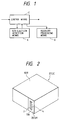
- Fig. 1 is a schematic view showing the basic structure of embodiments of the present invention.
- non-discharge detection means A for automatically detecting discharge failure in the ink discharge openings of an ink jet recording apparatus employed as the recording system of a facsimile apparatus; recovery process means B for effecting a recovery process on the ink discharge openings; and control means C for causing said non-discharge detection means A to effect the detection of discharge failure in response to the reception of a call signal, also causing said recovery process means B to effect a recovery process in case a non-discharge is detected, and initiating a reception process after the absence of non-discharge is detected by said non discharge detection means A.
- control means C is capable, for example, of interrupting the reception and providing an error alarm if the discharge failure is still detected after repetition of plural times of the detection of ink non-discharge and the recovery process explained above.
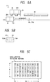
- FIGs. 2 and 3 illustrate an example of ink jet printer adapted for use as the recording system in a facsimile apparatus constituting an embodiment of the image communicating apparatus of the present invention.
- IJC detachable ink jet cartridge
- IJH ink jet head
- IT ink tank
- the ink jet head 20 slightly protrudes from the front face of the ink tank 10.
- Said ink jet cartridge 21 is of disposable type, detachably mounted on a carriage of the ink jet recording apparatus IJRA as will be explained later.
- a first ink tank 10 containing ink for supply to the ink jet head 20, is composed of an ink absorbent member, a container therefor and a cover member for closing said container (both not shown). Said ink tank 10 is filled with ink and supplies said ink to the ink jet head according to ink discharge therefrom.
- a front plate 4 is composed of a resinous material with high ink resistance, such as polysulfone, polyethersulfone, polyphenylene oxide or polypropylene.
- the ink jet cartridge 21 of the above-explained structure is detachably mounted on the carriage HC of the ink jet recording apparatus IJRA explained in the following, and effects formation of a recorded image by relative movement of the carriage HC and a recording material, in response to the entry of a recording signal.
- Fig. 3 is a perspective view of an example of the ink jet recording apparatus IJRA equipped with mechanisms for the above-mentioned operations.
- the ink jet head of the ink jet cartridge 20 is provided with nozzles for discharging ink toward a recording surface of a recording sheet supplied from a sheet feeding unit 25 onto a platen 24.
- a carriage (HC) 16, for supporting said recording head 20 is linked with a part of a driving belt 18 for transmitting the driving force of a driving motor 17, and is capable of reciprocating over the entire width of the recording sheet by sliding along mutually parallel two guide shafts 19A, 19B.
- a discharge recovery operation by ink suction (suction recovery) by suitable suction means (for example a suction pump) provided in the recovery unit 26 or by forced discharge of viscosified ink from the discharge openings by pressurizing ink with suitable pressurizing means provided in an ink supply path to the recording head 20 (pressurized recovery).
- suction recovery by suitable suction means (for example a suction pump) provided in the recovery unit 26 or by forced discharge of viscosified ink from the discharge openings by pressurizing ink with suitable pressurizing means provided in an ink supply path to the recording head 20 (pressurized recovery).
- the recording head is protected by said capping for example after the recording operation.
- Such a discharge recovery operation is conducted at the start of power supply, at the replacement of the recording head, or
- the blade 31 is made to protrude into the moving path of the recording head 20 at a suitable timing in the course of recording operation thereof or after the discharge recovery operation therefor by the recovery unit 26, thereby wiping the dew, liquid or dusts off said ink discharging surface of the recording head 20 by the movement thereof.
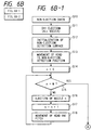
- a non-discharge detecting device as shown in Figs. 5A and 5B.
- Fig. 4 shows an example of the circuit of the facsimile apparatus embodying the present invention, wherein shown are a main CPU (central processing unit) 101 such as a microcomputer for controlling, through a bus 117, the entire apparatus for data transmission and reception; a ROM (read-only memory) 102 for storing various control programs for the CPU 101 as shown in Fig.
- main CPU central processing unit
- ROM read-only memory
- a work RAM (random access memory) 103 used as counters and registers of the CPU 101
- a modulator-demodulator (modem) 104 for data transmission
- a network control unit (NCU) 105 for connecting the modem 104 with a public telephone line
- a RAM 106 for registering data such as telephone numbers and abbreviated names
- an image RAM (DRAM) 107 for temporarily storing image data.
- a CCD (charge - coupled device) 108 serving as image pickup means of the original reading unit, converts an original image, focused though an imaging lens such as a rod lens array, into an electrical signal.
- a binary digitizing circuit 109 binarizes the output signal of the CCD 108.
- the recording head 20 is incorporated in a recording system, which is composed, in the present embodiment, of an ink jet recording apparatus of bubble jet type as shown in Figs. 2 and 3.
- a sub CPU 110 controls the carriage driving motor 17 for moving the recording head (20 in Fig. 2), the recovery motor 22 for driving the recovery unit 26, a non-discharge sensor 113 etc. and is provided with a ROM storing therein control programs for non-discharge check, recovery operation and image recording.
- An operation unit 114 is provided with a keyboard containing various keys 116 and a liquid crystal display unit (LCD) 115.
- LCD liquid crystal display unit
- Fig. 5A is a plan view of an example of the non-discharge detecting device employed in the present embodiment of the present invention
- Fig. 5B is a front view of a non-discharge sensor seen in a direction A shown in Fig. 5A.
- the non-discharge detecting device of the present embodiment is composed of a non-discharge detecting unit 120 and a non-discharge sensor 113.
- the non-discharge detecting unit 120 receives, instead of the ordinary recording sheet, the ink droplets discharged from the recording head 20 at the non-discharge checking operation to be explained later, and is provided, at the front part thereof, for example with a rolled sheet which can be advanced by a winding mechanism (not shown) utilizing a micromotor, or a white board (not shown) on which ink can be deposited and wiped off with an electric wiper (not shown).
- Said non-discharge detecting unit 120 is positioned either between the recording sheet guided by the platen 24 (cf. Fig. 3) and the cap 26A of the recovery unit 26 or outside said cap 26A and substantially adjacent thereto, in such a manner that said rolled sheet or white board is on the substantially same plane as the printing surface 34 of the recording sheet.
- Said non-discharge sensor 113 is provided with a photoelectric converting element array 113A for detecting, in the unit of each dot, the ink discharged from the recording head 20 and deposited on the rolled sheet or the white board of the non-discharge detecting unit 120, and said array 113A is positioned, as shown in Fig. 5B, parallel to the nozzles 13A of the recording head 20 and substantially as long as or somewhat longer than the array of said nozzles.
- Said non-discharge sensor 113 is mounted on the carriage 16 (cf. Fig. 3) and close to the recording head 20, and the photoelectric converting element array 113A is somewhat retracted from the nozzles of the recording head 20 so as not to contact with the wiper blade 31.
- a light source for illuminating said rolled sheet may be provided at the side of the non-discharge sensor 113 as in a photointerrupter, or may be positioned at the rear side of the rolled sheet or the semi-transparent white board, in which case the sensor 113 detects the transmitted light.
- Fig. 5C shows an example of the non-discharge detecting pattern to be recorded on the non-discharge detecting unit 120.
- This pattern is obtained by effecting ink discharges from the nozzles in succession, by a nozzle at a time from top to bottom, while the carriage 16 is moved from left to right along the guides 19A, 19B, toward the non-discharge detecting unit 120, wherein the hatched areas indicate the ink deposited positions, and N indicates the number of discharge openings.
- non-discharge detecting pattern is not limited to what has been explained above, and the non-discharge of ink may also be identified for example by discharging ink plural times in succession from a same discharge opening, or by simultaneously discharging ink from each of plural groups in which all the discharge openings are divided, and inspecting whether the average density is same among different groups.
- the presence of the non-discharge detecting unit 120 as shown in Fig. 5A allows to check the non-discharge without smearing the recording sheet, but it is naturally possible also to record the non-discharge detecting pattern directly on a marginal part of the recording sheet and to detect said pattern with the non-discharge sensor 113.
- Said marginal area can for example be a received message area for recording the date and time of reception and the sender of the received message.
- Fig. 6A shows a main routine executed by the CPU 101
- Fig. 6B shows a non-discharge checking subroutine to be executed by the sub CPU 110.
- the main CPU 101 upon detecting a call signal Ci of 16 Hz transmitted from an external transmitter through the NCU 105 (step S1), sends an instruction for non-discharge check to the sub CPU 110 (step S2), and effects a normal reception process only after receiving, from the sub CPU 110, a non-detection (OK) communication indicating the absence of non-discharging openings (step S3).
- a call signal Ci of 16 Hz transmitted from an external transmitter through the NCU 105
- step S2 sends an instruction for non-discharge check to the sub CPU 110
- step S3 effects a normal reception process only after receiving, from the sub CPU 110, a non-detection (OK) communication indicating the absence of non-discharging openings
- step S4 an instruction for recovery process is given to the sub CPU 110 for effecting the recovery process to be explained later (step S4), and, if the number of recovery processes does not reach a predetermined number (step S5), the sequence returns to the step S2 to repeat the above-explained procedure. If non-discharging openings are still present even after the number of recovery processes exceeds the predetermined number, an error process to be explained later is executed (step S6).
- the non-discharge check and the recovery process explained above are conducted in a period after the reception of the Ci signal and before a pre-procedure for discriminating whether or not to effect automatic reception, almost simultaneously with the checks for the presence of recording sheet and for the opened state of the cover of the recording system. Consequently, for practical purpose, the loop of aid non-discharge check and recovery process is preferably executed within a period of 10 to 15 seconds, since a period as long as 1 to 2 minutes would be inconvenient also in consideration of the convenience of the transmitting side.
- the usual head recovery process by covering the recording head 20 with the cap 26A and sucking the ink from the discharge openings by a suction motor (not shown) in the recovery unit 26, is not suitable as the recovery operation in the step S4 as it takes a relatively long time.
- the recovery process in the step S4 of the present embodiment is conducted, for example, by moving the recording head 20 by the motor 17 to the position of the cap 26A and applying drive pulses to all the heat generating elements of the discharge openings of the recording head 20, thereby effecting plural forced ink discharges, not intended for image recording, toward the cap 26A, from all the discharge openings.
- the cap 26A need not cover the recording head 20 in this operation, and said ink discharge is conducted while the cap 26A is separated from the recording head 20, and the ink discharged to said cap 26A is recovered in the recovery unit 26.
- This recovery process is similar to so-called idle ink discharge for preventing the clogging of openings, but the number of discharges is preferably about one order larger (for example 100 times) than that in the idle ink discharge. Also the number of loops in the step S5 is selected at a value matching a tolerable time (for example 15 seconds). Said number of loops in the step S5 may be directly controlled by the time by means of a timer counting the reference clock signals, instead of the count by the counter.
- the error process in the step S6 sends an error signal to the transmitting side thereby interrupting the reception, and displays a message for discharge failure on the LCD 115 of the operation unit 114 shown in Fig. 4 or flashes a lamp to inform the operator of the failure in the recording head. Preferably a buzzer sound is given simultaneously.
- the operator replaces the loaded ink jet cartridge 21 with a new one, or effects forced ink suction by the head recovery device 26 followed by a non-discharge check, and, if the recovery is not yet achieved, effects ink jet cartridge replacement.
- the non-discharge check is preferably made instructable from a key 116 of the operation unit.
- the sub CPU 110 moves the recording head 20 by the driving motor 17 to the position of the cap 26A, and applies driving pulses to all the discharge openings of the recording head 20, thereby effecting forced idle discharges for example about 10 times (step S11).
- the non-discharge detecting surface of the non-discharge detecting unit 120 shown in Fig. 5A is initialized by advancing the rolled sheet with the micromotor to expose a new sheet surface, or by cleaning the white board with the electric wiper (step S12).
- the recording head 20 is moved by the driving motor 17 and the carriage 16 to the non-discharge detecting position between the platen 24 and the recovery device 26 (step S13), and the count n of an internal counter is set at "0" (step S14).
- a non-discharge detecting pattern as shown in Fig. 5C is recorded on the non-discharge detecting surface of the non-discharge detecting unit 120.
- Fig. 5C shows a state in which discharge failure is absent in all the discharge openings.
- step S22 there is discriminated whether said count n has reached the number N of the discharge openings of the recording head 20 (step S22), and, if not, the n-th line is read by the non-discharge sensor 113 (step S23). If said line is white, namely without the discharges of ink (step S24), the detection of non-discharge is informed to the main CPU 101 (step S28). Said informing may be conducted by varying the value of a predetermined flag.
- step S24 identifies that said line is not all white, the count n of the internal counter is increased by "1" (step S25), then the driving motor 17 is activated to move the non-discharge sensor 113 by a pitch (step S26), and the sequence returns to the step S22 to repeat the above-explained procedure.
- step S27 If the count n reaches the value N through the repetition of the loop of the steps S22 to S26, all the discharge openings have normally discharged ink without failure, so that the absence of detection of the non-discharge is informed to the main CPU 101 (step S27).
- Said informing may be conducted, as explained above, by varying the value of a predetermined flag.
- control sequence of the present embodiment is shared by the main CPU 101 and the sub CPU 110, but the present invention is not limited by such embodiment and a similar control operation can naturally be conducted by a single CPU.
- the present invention is applicable not only to the above-explained serial printer but also to a facsimile apparatus equipped with an ink jet recording apparatus with a recording head of full-line type, having a length corresponding to the maximum width of recording medium recordable by said apparatus as shown in Figs. 7 and 8.
- paired rollers 201A, 201B for supporting and transporting a recording medium R in a sub scanning direction Vs indicated by an arrow; and full-line multi type recording heads 202BK, 202Y, 202M and 202C arranged in this order from the upstream side of the transporting direction of the recording medium R and respectively having nozzles over the entire width of the recording medium R for respectively recording black, yellow, magenta and cyan colors.
- a recovery system 200 is brought, at the discharge recovery operation, to a position opposite to the recording heads 202BK - 202C instead of the recording medium R.
- the number of such discharge recovery operations can be significantly reduced by a preliminary heating conducted at a suitable timing.
- Fig. 8 is an external view of one of the recording heads 202BK - 202C shown in Fig. 7, and shows ink discharge openings 210, an ink supply pipe 211, plural integrated circuits 212 for driving the electrothermal converting elements, and terminals 213, 214.
- Control sequences similar to those shown in Figs. 6A and 6B may also be employed in applying the present invention to a facsimile apparatus equipped with a printer of such full-line type, but, in such case, the structure can be made relatively simple by discharging the ink directly onto the recording sheet and positioning the non-discharge sensor in the down-stream side in the transporting direction of the recording sheet.
- the present invention is particularly advantageously applicable to the recording head and recording apparatus of bubble jet system, because such system has the ability of attaining higher density and definition in the recording.
- the representative structure and principle of such bubble jet system are preferably based on the basic principle disclosed for example in the U.S. Patents Nos. 4,723,129 and 4,740,796.
- This system is applicable to so-called on-demand type and continuous type ink jet recording, but is particularly effective in the on-demand recording, by providing an electrothermal converting element positioned corresponding to each liquid path or a sheet containing liquid (ink) with at least a drive signal corresponding to the recording information and inducing a rapid temperature increase exceeding nucleus boiling, thereby causing said converting element to generate thermal energy for inducing membrane boiling on a heat action surface of the recording head, thus generating a bubble in said liquid (ink) corresponding one-to-one to said drive signal.
- the liquid (ink) is discharged from a discharge opening by the expansion and contraction of said bubble, thereby forming at least a droplet.
- a pulse-shaped driven signal is particularly preferable as it achieves immediate expansion and contraction of the bubble, thereby realizing highly responsive ink discharge.
- Such pulse-shaped drive signal is preferably that disclosed in the U.S. Patents No. 4,463,359 and 4,345,262.
- a further improved recording can be achieved by the conditions disclosed in the U.S. Patent No. 4,313,124 concerning the temperature increase rate of said thermal action surface.
- the present invention includes the structures of the recording head not only obtained by the combinations of discharge openings, liquid paths and electrothermal converting members disclosed in the above-mentioned patents (those with linear or rectangularly bent liquid paths), but also the structures disclosed in the U.S. Patents Nos. 4,558,333 and 4,459,600 in which the thermal action portion is provided in a bent area.
- the present invention is also effective in a structure having a common slit as the discharge opening for plural electrothermal converting elements as disclosed in the Japanese Patent Appln. JP-A-59123670 or a structure having an aperture for absorbing the pressure wave of thermal energy corresponding to the discharge opening as disclosed in the Japanese Patent Appln. JP-A-59138461, because the recording can be securely and efficiently conducted regardless of the form of the recording head.
- recovery means or auxiliary means for the recording head such as capping means, cleaning means, pressurizing means or suction means, preliminary heating means composed of electrothermal converting elements and/or other heating elements, and means for effecting a preliminary discharge mode different from that for image recording, in order to achieve stable recording operation.
Landscapes
- Engineering & Computer Science (AREA)
- Multimedia (AREA)
- Signal Processing (AREA)
- Health & Medical Sciences (AREA)
- Biomedical Technology (AREA)
- General Health & Medical Sciences (AREA)
- Human Computer Interaction (AREA)
- Ink Jet (AREA)
Description
- The present invention relates to an image communicating apparatus such as a facsimile apparatus, and more particularly an image communicating apparatus equipped with an ink jet printer provided with plural ink discharge openings.
- There has recently been developed an ink jet printer for recording characters or an image by discharging ink from discharge openings or orifices to a recording material, utilizing bubbles generated by thermal energy. Because the heat generating member (heater) provided in each discharge opening is significantly smaller than the piezoelectric element employed in the conventional ink jet printers, this ink jet printer enables a high-density arrangement of multiple discharge openings, thereby providing a recorded image of high quality. In addition it has additional advantages such as high speed and low noises.
- On the other hand, the facsimile apparatus are required not only to transmit images at high speed, but also to receive images with high image quality and at high speed. In consideration of the above-mentioned features, the ink jet printer which discharges ink toward the recording material utilizing bubbles generated by thermal energy is considered as one of the printers capable of meeting such requirements, but there has not been provided the facsimile apparatus equipped with such ink jet printer.
- In such ink jet printer, the ink discharge openings of the recording head may be clogged by the ink which is viscosified by a pause in the use of the recording head, or in a low humidity situation or by a difference in the frequency of use, or by the deposition of dust. For this reason there has been employed a discharge recovery mechanism for removing such viscosified ink by pressurizing the discharge openings from the interior of the recording head, or by sucking said ink from a protective cap for covering the discharge openings of the recording head. Also when the recording head is not in use, the discharge openings thereof are covered with a cap to prevent ink discharge failure.
- However, despite such countermeasures, the ink discharge openings may be still clogged in case of a prolonged pause in the use of the recording head or under a relatively dry ambient conditions because the ink path communicating with each ink discharge opening is extremely narrow. Also ink discharge openings used very infrequently in a recording operation may be clogged in the next recording operation. Such clogging results in white streaks or stripes on the recorded image, thus deteriorating the quality thereof and causing lack of information to be recorded. Consequently, the operator has conventionally checked for discharge failure by visual observation of the state of the recorded image, and has manually instructed the above-explained recovery operations in case discharge failure is identified in some discharge openings.
- However, in realizing a facsimile apparatus equipped with such ink jet printer, such manual inspection of or instruction for the discharge failure is extremely inconvenient because the once received image signal has to be wasted, and there will result a drawback that the resending of image signal has to be requested manually for example by a phonecall after signal reception is completed. Also such inspection for discharge failure may be erroneously forgotten or such request for signal resending may not possible due to the office hours of the sender.
- There is disclosed in International Patent Application WO-A-8902827 a process and arrangement for the automatic performance checking of printing ink devices. To ensure fully automatic performance checking, a printing ink device has a cleaning and rinsing device and an ink drop sensor. When a fully automatic self-check procedure is called before the actual printing operation or after printing for a specified period of time, the printing ink head is cleaned and rinsed in a rest position and its performance is then checked in a spray test by an ink drop sensor. If the results of the spray test are satisfactory, the printing operation can be resumed. If the results of two consecutive spray test are unsatisfactory, the printing device is placed in a breakdown position and the printing operation is brought to a halt.
- According to the present invention, there is provided an image communicating apparatus comprising:
- (a) an ink jet printer having a recording head with a plurality of discharge openings and a plurality of discharge energy generating elements each of which is energisable to cause ink to be discharged from a corresponding discharge outlet onto a recording medium;
- (b) means for receiving a call signal from another image communicating apparatus;
- (c) means for detecting whether any of the discharge outlets of the recording head is blocked;
- (d) means for inhibiting receipt of image data from the other image communicating apparatus;
- (e) clearing means operable to clear a blocked discharge opening, the clearing means comprising a recovery means having means for causing ink to be discharged from the discharge openings without energising the discharge energy generating elements and means for receiving the discharged ink; and
- (f) control means adapted to operate the inhibiting means in response to the detection of a non-discharging discharge opening after receipt of the call signal and to energise the clearing means before the receipt of image data from the other image communicating apparatus; characterised in that:
- (g) the clearing means comprises additional recovery means comprising means for energising the discharge energy generating elements and, in response to detection of a blocked discharge opening after receipt of a call signal from the other communicating apparatus, the control means is operable to activate the additional recovery means to energise all of the discharge energy generating elements one or more times before the receipt of image data from the other image communicating apparatus to cause ink to be discharged toward the ink receiving means and to operate the inhibiting means to inhibit receipt of image data from the other image communicating apparatus when the detecting means detects that a discharge opening is non-discharging after the additional recovery means has been activated a predetermined number of times.
- Embodiments of the invention will now be described by way of example only and with reference to the accompanying drawings in which:
- Fig. 1 is a block diagram of the basic structure embodying the present invention;
- Fig. 2 is a perspective view of an example of the ink jet cartridge of bubble jet system in which the present invention is applicable;
- Fig. 3 is a perspective view of an example of the recording system of a facsimile apparatus in which the present invention is applicable, employing the ink jet cartridge shown in Fig. 2;
- Fig. 4 is a block diagram of an example of the facsimile apparatus embodying the present invention;
- Fig. 5A is a plan view of the arrangement of a non-discharge detection device embodying the present invention;
- Fig. 5B is a front view of the non-discharge detection sensor shown in Fig. 5A, seen from a direction A shown therein;
- Fig. 5C is a view showing an example of non-discharge detection pattern printed on a detection surface of the non-discharge detecting device;
- Fig. 6A is a flow chart of the control sequence of an embodiment of the present invention;
- Fig. 6B is a flow chart of the control sequence for non-discharge check in the embodiment of the present invention;
- Fig. 7 is a schematic perspective view of a full line ink jet recording apparatus constituting another embodiment of the present invention;
- Fig. 8 is a perspective view of the recording head employed in the embodiment shown in Fig. 7;
- Now the present invention will be clarified in detail by embodiments thereof shown in the attached drawings.
- Fig. 1 is a schematic view showing the basic structure of embodiments of the present invention. There are provided non-discharge detection means A for automatically detecting discharge failure in the ink discharge openings of an ink jet recording apparatus employed as the recording system of a facsimile apparatus; recovery process means B for effecting a recovery process on the ink discharge openings; and control means C for causing said non-discharge detection means A to effect the detection of discharge failure in response to the reception of a call signal, also causing said recovery process means B to effect a recovery process in case a non-discharge is detected, and initiating a reception process after the absence of non-discharge is detected by said non discharge detection means A.
- Also the control means C is capable, for example, of interrupting the reception and providing an error alarm if the discharge failure is still detected after repetition of plural times of the detection of ink non-discharge and the recovery process explained above.
- Figs. 2 and 3 illustrate an example of ink jet printer adapted for use as the recording system in a facsimile apparatus constituting an embodiment of the image communicating apparatus of the present invention. There are shown an ink jet head (recording head) 20 of a system for discharging ink toward a recording sheet, utilizing bubbles generated by thermal energy; a detachable ink jet cartridge (IJC) 21 integral with an ink jet head (IJH) 21 and equipped with an ink tank (IT) 10 for supplying ink to said ink jet head; and the main body of the ink jet recording apparatus IJRA.
- in the
ink jet cartridge 21 of the present embodiment, as will be apparent from a perspective view in Fig. 2, theink jet head 20 slightly protrudes from the front face of the ink tank 10. Saidink jet cartridge 21 is of disposable type, detachably mounted on a carriage of the ink jet recording apparatus IJRA as will be explained later. - A first ink tank 10, containing ink for supply to the
ink jet head 20, is composed of an ink absorbent member, a container therefor and a cover member for closing said container (both not shown). Said ink tank 10 is filled with ink and supplies said ink to the ink jet head according to ink discharge therefrom. - In the present embodiment, a
front plate 4 is composed of a resinous material with high ink resistance, such as polysulfone, polyethersulfone, polyphenylene oxide or polypropylene. - The
ink jet cartridge 21 of the above-explained structure is detachably mounted on the carriage HC of the ink jet recording apparatus IJRA explained in the following, and effects formation of a recorded image by relative movement of the carriage HC and a recording material, in response to the entry of a recording signal. - Fig. 3 is a perspective view of an example of the ink jet recording apparatus IJRA equipped with mechanisms for the above-mentioned operations.
- Referring to Fig. 3, the ink jet head of the
ink jet cartridge 20 is provided with nozzles for discharging ink toward a recording surface of a recording sheet supplied from asheet feeding unit 25 onto aplaten 24. A carriage (HC) 16, for supporting saidrecording head 20, is linked with a part of a drivingbelt 18 for transmitting the driving force of a drivingmotor 17, and is capable of reciprocating over the entire width of the recording sheet by sliding along mutually parallel twoguide shafts - A
head recovery unit 26, positioned at an end of the moving path of therecording head 20, for example at a position corresponding to the home position of therecording head 20, effects capping therefor when activated by amotor 22 through atransmission mechanism 23. In combination with the capping operation by acap 26A, there is conducted a discharge recovery operation by ink suction (suction recovery) by suitable suction means (for example a suction pump) provided in therecovery unit 26 or by forced discharge of viscosified ink from the discharge openings by pressurizing ink with suitable pressurizing means provided in an ink supply path to the recording head 20 (pressurized recovery). Also the recording head is protected by said capping for example after the recording operation. Such a discharge recovery operation is conducted at the start of power supply, at the replacement of the recording head, or at a pause in the recording operation exceeding a predetermined time. - A wiping blade or a
wiper 31, positioned at a side of thehead recovery unit 26 and made of silicone rubber, is supported in a cantilever mechanism by ablade support member 31A and is activated also by themotor 22 and thetransmission mechanism 23 for engagement with the ink discharging surface of therecording head 20. Thus theblade 31 is made to protrude into the moving path of therecording head 20 at a suitable timing in the course of recording operation thereof or after the discharge recovery operation therefor by therecovery unit 26, thereby wiping the dew, liquid or dusts off said ink discharging surface of therecording head 20 by the movement thereof. - Between the
platen 20 and therecovery unit 26, there is provided a non-discharge detecting device as shown in Figs. 5A and 5B. - Fig. 4 shows an example of the circuit of the facsimile apparatus embodying the present invention, wherein shown are a main CPU (central processing unit) 101 such as a microcomputer for controlling, through a
bus 117, the entire apparatus for data transmission and reception; a ROM (read-only memory) 102 for storing various control programs for theCPU 101 as shown in Fig. 6A; a work RAM (random access memory) 103 used as counters and registers of theCPU 101; a modulator-demodulator (modem) 104 for data transmission; a network control unit (NCU) 105 for connecting themodem 104 with a public telephone line; aRAM 106 for registering data such as telephone numbers and abbreviated names; and an image RAM (DRAM) 107 for temporarily storing image data. - A CCD (charge - coupled device) 108, serving as image pickup means of the original reading unit, converts an original image, focused though an imaging lens such as a rod lens array, into an electrical signal. A
binary digitizing circuit 109 binarizes the output signal of theCCD 108. - The
recording head 20 is incorporated in a recording system, which is composed, in the present embodiment, of an ink jet recording apparatus of bubble jet type as shown in Figs. 2 and 3. Asub CPU 110 controls thecarriage driving motor 17 for moving the recording head (20 in Fig. 2), therecovery motor 22 for driving therecovery unit 26, anon-discharge sensor 113 etc. and is provided with a ROM storing therein control programs for non-discharge check, recovery operation and image recording. - An
operation unit 114 is provided with a keyboard containingvarious keys 116 and a liquid crystal display unit (LCD) 115. - Fig. 5A is a plan view of an example of the non-discharge detecting device employed in the present embodiment of the present invention, and Fig. 5B is a front view of a non-discharge sensor seen in a direction A shown in Fig. 5A. The non-discharge detecting device of the present embodiment is composed of a
non-discharge detecting unit 120 and anon-discharge sensor 113. Thenon-discharge detecting unit 120 receives, instead of the ordinary recording sheet, the ink droplets discharged from therecording head 20 at the non-discharge checking operation to be explained later, and is provided, at the front part thereof, for example with a rolled sheet which can be advanced by a winding mechanism (not shown) utilizing a micromotor, or a white board (not shown) on which ink can be deposited and wiped off with an electric wiper (not shown). Said non-discharge detectingunit 120 is positioned either between the recording sheet guided by the platen 24 (cf. Fig. 3) and thecap 26A of therecovery unit 26 or outside saidcap 26A and substantially adjacent thereto, in such a manner that said rolled sheet or white board is on the substantially same plane as the printing surface 34 of the recording sheet. - Said
non-discharge sensor 113 is provided with a photoelectric convertingelement array 113A for detecting, in the unit of each dot, the ink discharged from therecording head 20 and deposited on the rolled sheet or the white board of thenon-discharge detecting unit 120, and saidarray 113A is positioned, as shown in Fig. 5B, parallel to thenozzles 13A of therecording head 20 and substantially as long as or somewhat longer than the array of said nozzles. Saidnon-discharge sensor 113 is mounted on the carriage 16 (cf. Fig. 3) and close to therecording head 20, and the photoelectric convertingelement array 113A is somewhat retracted from the nozzles of therecording head 20 so as not to contact with thewiper blade 31. A light source for illuminating said rolled sheet may be provided at the side of thenon-discharge sensor 113 as in a photointerrupter, or may be positioned at the rear side of the rolled sheet or the semi-transparent white board, in which case thesensor 113 detects the transmitted light. - Fig. 5C shows an example of the non-discharge detecting pattern to be recorded on the
non-discharge detecting unit 120. This pattern is obtained by effecting ink discharges from the nozzles in succession, by a nozzle at a time from top to bottom, while thecarriage 16 is moved from left to right along theguides non-discharge detecting unit 120, wherein the hatched areas indicate the ink deposited positions, and N indicates the number of discharge openings. However the non-discharge detecting pattern is not limited to what has been explained above, and the non-discharge of ink may also be identified for example by discharging ink plural times in succession from a same discharge opening, or by simultaneously discharging ink from each of plural groups in which all the discharge openings are divided, and inspecting whether the average density is same among different groups. - Also in the present embodiment, the presence of the
non-discharge detecting unit 120 as shown in Fig. 5A allows to check the non-discharge without smearing the recording sheet, but it is naturally possible also to record the non-discharge detecting pattern directly on a marginal part of the recording sheet and to detect said pattern with thenon-discharge sensor 113. Said marginal area can for example be a received message area for recording the date and time of reception and the sender of the received message. - In the following there will be explained the control sequence of the present embodiment, with reference to flow charts shown in Figs. 6A and 6B.
- Fig. 6A shows a main routine executed by the
CPU 101, while Fig. 6B shows a non-discharge checking subroutine to be executed by thesub CPU 110. At first referring to Fig. 6A, themain CPU 101, upon detecting a call signal Ci of 16 Hz transmitted from an external transmitter through the NCU 105 (step S1), sends an instruction for non-discharge check to the sub CPU 110 (step S2), and effects a normal reception process only after receiving, from thesub CPU 110, a non-detection (OK) communication indicating the absence of non-discharging openings (step S3). However, in case a detection (NG) response, indicating the presence of non-discharging openings, is received from thesub CPU 110, an instruction for recovery process is given to thesub CPU 110 for effecting the recovery process to be explained later (step S4), and, if the number of recovery processes does not reach a predetermined number (step S5), the sequence returns to the step S2 to repeat the above-explained procedure. If non-discharging openings are still present even after the number of recovery processes exceeds the predetermined number, an error process to be explained later is executed (step S6). - The non-discharge check and the recovery process explained above are conducted in a period after the reception of the Ci signal and before a pre-procedure for discriminating whether or not to effect automatic reception, almost simultaneously with the checks for the presence of recording sheet and for the opened state of the cover of the recording system. Consequently, for practical purpose, the loop of aid non-discharge check and recovery process is preferably executed within a period of 10 to 15 seconds, since a period as long as 1 to 2 minutes would be inconvenient also in consideration of the convenience of the transmitting side. Therefore, the usual head recovery process by covering the
recording head 20 with thecap 26A and sucking the ink from the discharge openings by a suction motor (not shown) in therecovery unit 26, is not suitable as the recovery operation in the step S4 as it takes a relatively long time. - Thus the recovery process in the step S4 of the present embodiment is conducted, for example, by moving the
recording head 20 by themotor 17 to the position of thecap 26A and applying drive pulses to all the heat generating elements of the discharge openings of therecording head 20, thereby effecting plural forced ink discharges, not intended for image recording, toward thecap 26A, from all the discharge openings. Thecap 26A need not cover therecording head 20 in this operation, and said ink discharge is conducted while thecap 26A is separated from therecording head 20, and the ink discharged to saidcap 26A is recovered in therecovery unit 26. This recovery process is similar to so-called idle ink discharge for preventing the clogging of openings, but the number of discharges is preferably about one order larger (for example 100 times) than that in the idle ink discharge. Also the number of loops in the step S5 is selected at a value matching a tolerable time (for example 15 seconds). Said number of loops in the step S5 may be directly controlled by the time by means of a timer counting the reference clock signals, instead of the count by the counter. - The error process in the step S6 sends an error signal to the transmitting side thereby interrupting the reception, and displays a message for discharge failure on the
LCD 115 of theoperation unit 114 shown in Fig. 4 or flashes a lamp to inform the operator of the failure in the recording head. Preferably a buzzer sound is given simultaneously. In response to such error information, the operator replaces the loadedink jet cartridge 21 with a new one, or effects forced ink suction by thehead recovery device 26 followed by a non-discharge check, and, if the recovery is not yet achieved, effects ink jet cartridge replacement. For this purpose, the non-discharge check is preferably made instructable from a key 116 of the operation unit. - In the following there will be explained the details of the non-discharge check in the present embodiment, with reference to a flow chart shown in Fig. 6B. At first, upon receiving an instruction for the non-discharge check from the main CPU 101 (step S10), the
sub CPU 110 moves therecording head 20 by the drivingmotor 17 to the position of thecap 26A, and applies driving pulses to all the discharge openings of therecording head 20, thereby effecting forced idle discharges for example about 10 times (step S11). Then the non-discharge detecting surface of thenon-discharge detecting unit 120 shown in Fig. 5A is initialized by advancing the rolled sheet with the micromotor to expose a new sheet surface, or by cleaning the white board with the electric wiper (step S12). Subsequently therecording head 20 is moved by the drivingmotor 17 and thecarriage 16 to the non-discharge detecting position between theplaten 24 and the recovery device 26 (step S13), and the count n of an internal counter is set at "0" (step S14). - Then there is discriminated whether said count n has reached the number N of the discharge openings of the recording head 20 (step S15), and, if not, a drive pulse is applied to an n-th (0-th at first) discharge opening to cause ink discharge of a dot (step S16). Then said count n of the internal counter is increased by "1" (step S17), and the
motor 17 is activated to shift therecording head 20 by a pitch (step S18). The sequence then returns to the step S15, and the above-explained procedure is repeated until a state n = N is reached. - Upon ink discharge from the last discharge opening of the
recording head 20, a non-discharge detecting pattern as shown in Fig. 5C is recorded on the non-discharge detecting surface of thenon-discharge detecting unit 120. Fig. 5C shows a state in which discharge failure is absent in all the discharge openings. Thus, if the step S15 identifies n = N, the drivingmotor 17 is activated to move therecording head 20 to the idle discharge position corresponding to thecap 26A (step S19), then thenon-discharge sensor 113 is moved to the non-discharge detecting position of the detecting unit 120 (step S20), and the count n of the internal sensor is set at "0" (step S21). - Then there is discriminated whether said count n has reached the number N of the discharge openings of the recording head 20 (step S22), and, if not, the n-th line is read by the non-discharge sensor 113 (step S23). If said line is white, namely without the discharges of ink (step S24), the detection of non-discharge is informed to the main CPU 101 (step S28). Said informing may be conducted by varying the value of a predetermined flag.
- If the step S24 identifies that said line is not all white, the count n of the internal counter is increased by "1" (step S25), then the driving
motor 17 is activated to move thenon-discharge sensor 113 by a pitch (step S26), and the sequence returns to the step S22 to repeat the above-explained procedure. - If the count n reaches the value N through the repetition of the loop of the steps S22 to S26, all the discharge openings have normally discharged ink without failure, so that the absence of detection of the non-discharge is informed to the main CPU 101 (step S27). Said informing may be conducted, as explained above, by varying the value of a predetermined flag.
- The control sequence of the present embodiment is shared by the
main CPU 101 and thesub CPU 110, but the present invention is not limited by such embodiment and a similar control operation can naturally be conducted by a single CPU. - The present invention is applicable not only to the above-explained serial printer but also to a facsimile apparatus equipped with an ink jet recording apparatus with a recording head of full-line type, having a length corresponding to the maximum width of recording medium recordable by said apparatus as shown in Figs. 7 and 8.
- Referring to Fig. 7, there are shown paired
rollers 201A, 201B for supporting and transporting a recording medium R in a sub scanning direction Vs indicated by an arrow; and full-line multi type recording heads 202BK, 202Y, 202M and 202C arranged in this order from the upstream side of the transporting direction of the recording medium R and respectively having nozzles over the entire width of the recording medium R for respectively recording black, yellow, magenta and cyan colors. - A
recovery system 200 is brought, at the discharge recovery operation, to a position opposite to the recording heads 202BK - 202C instead of the recording medium R. In the present embodiment, however, the number of such discharge recovery operations can be significantly reduced by a preliminary heating conducted at a suitable timing. - Fig. 8 is an external view of one of the recording heads 202BK - 202C shown in Fig. 7, and shows
ink discharge openings 210, anink supply pipe 211, pluralintegrated circuits 212 for driving the electrothermal converting elements, andterminals - Control sequences similar to those shown in Figs. 6A and 6B may also be employed in applying the present invention to a facsimile apparatus equipped with a printer of such full-line type, but, in such case, the structure can be made relatively simple by discharging the ink directly onto the recording sheet and positioning the non-discharge sensor in the down-stream side in the transporting direction of the recording sheet.
- The present invention is not limited to the foregoing embodiments but is subject to various modifications.
- Among various ink jet recording methods, the present invention is particularly advantageously applicable to the recording head and recording apparatus of bubble jet system, because such system has the ability of attaining higher density and definition in the recording.
- The representative structure and principle of such bubble jet system are preferably based on the basic principle disclosed for example in the U.S. Patents Nos. 4,723,129 and 4,740,796. This system is applicable to so-called on-demand type and continuous type ink jet recording, but is particularly effective in the on-demand recording, by providing an electrothermal converting element positioned corresponding to each liquid path or a sheet containing liquid (ink) with at least a drive signal corresponding to the recording information and inducing a rapid temperature increase exceeding nucleus boiling, thereby causing said converting element to generate thermal energy for inducing membrane boiling on a heat action surface of the recording head, thus generating a bubble in said liquid (ink) corresponding one-to-one to said drive signal. The liquid (ink) is discharged from a discharge opening by the expansion and contraction of said bubble, thereby forming at least a droplet. A pulse-shaped driven signal is particularly preferable as it achieves immediate expansion and contraction of the bubble, thereby realizing highly responsive ink discharge. Such pulse-shaped drive signal is preferably that disclosed in the U.S. Patents No. 4,463,359 and 4,345,262. A further improved recording can be achieved by the conditions disclosed in the U.S. Patent No. 4,313,124 concerning the temperature increase rate of said thermal action surface.
- The present invention includes the structures of the recording head not only obtained by the combinations of discharge openings, liquid paths and electrothermal converting members disclosed in the above-mentioned patents (those with linear or rectangularly bent liquid paths), but also the structures disclosed in the U.S. Patents Nos. 4,558,333 and 4,459,600 in which the thermal action portion is provided in a bent area. In addition the present invention is also effective in a structure having a common slit as the discharge opening for plural electrothermal converting elements as disclosed in the Japanese Patent Appln. JP-A-59123670 or a structure having an aperture for absorbing the pressure wave of thermal energy corresponding to the discharge opening as disclosed in the Japanese Patent Appln. JP-A-59138461, because the recording can be securely and efficiently conducted regardless of the form of the recording head.
- Also in apparatus embodying the present invention, there is provided recovery means or auxiliary means for the recording head, such as capping means, cleaning means, pressurizing means or suction means, preliminary heating means composed of electrothermal converting elements and/or other heating elements, and means for effecting a preliminary discharge mode different from that for image recording, in order to achieve stable recording operation.
- Also there may be employed not only a recording head for a single ink but also plural recording heads corresponding to plural inks different in colors and/or density.
Claims (9)
- An image communicating apparatus comprising:(a) an ink jet printer having a recording head (20) with a plurality of discharge openings (21,210) and a plurality of discharge energy generating elements each of which is energisable to cause ink to be discharged from a corresponding discharge outlet onto a recording medium;(b) means (101) for receiving a call signal (Ci) from another image communicating apparatus;(c) means (A) for detecting whether any of the discharge outlets of the recording head is blocked;(d) means for inhibiting receipt of image data from the other image communicating apparatus;(e) clearing means (B) operable to clear a blocked discharge opening, the clearing means comprising a recovery means (26) having means for causing ink to be discharged from the discharge openings without energising the discharge energy generating elements and means (26A) for receiving the discharged ink; and(f) control means (C) adapted to operate the inhibiting means in response to the detection of a non-discharging discharge opening after receipt of the call signal and to energise the clearing means (B) before the receipt of image data from the other image communicating apparatus;characterised in that:
(g) the clearing means (B) comprises additional recovery means comprising means for energising the discharge energy generating elements and, in response to detection of a blocked discharge opening after receipt of a call signal from the other communicating apparatus, the control means (C) is operable to activate the additional recovery means to energise all of the discharge energy generating elements one or more times before the receipt of image data from the other image communicating apparatus to cause ink to be discharged toward the ink receiving means and to operate the inhibiting means to inhibit receipt of image data from the other image communicating apparatus when the detecting means detects that a discharge opening is non-discharging after the additional recovery means has been activated a predetermined number of times. - An image communicating apparatus as claimed in claim 1 in which the detection means (A) comprises means to eject either sequentially or simultaneously ink from all the nozzles onto an area of a target testing surface and then reading that area to visually detect whether the pattern of ink thereon is defective and thus indicative of a blocked nozzle or nozzles.
- An apparatus according to claim 1, wherein said detection means (A) comprises:a detection part (120) for receiving ink discharged from the recording head (20); anda sensor (113) for detecting each of plural ink dots deposited on a surface of said detection part (120).
- An apparatus according to claim 3, wherein said recording head (20) is arranged to record a pattern image (Fig. 5c) on the detection part (120), said pattern image having a dot arrangement such that dots recorded by ink droplets discharged from respective discharge openings (210) of said recording head (20) are distinguishable from each other.
- An apparatus according to claim 4, having means to cause ink to be discharged from successive nozzles (201) as the head (20) is scanned in relation to the said detection part (120) to thus form a pattern to be detected.
- An image communicating apparatus as claimed in any previous claim in which there is means to effect the ink energization and recovery at least ten times in succession.
- An image communicating apparatus as claimed in claim 6 in which the number of times the ink energization and recovery is effected sequentially is determined by a timer adapted to count reference clock signals.
- An image communicating apparatus as claimed in claim 2 in which the target comprises a white board having wiper means associated therewith.
- An image communicating apparatus as claimed in claim 2 in which the target comprises a roll of paper which can be moved incrementally into the target area.
Applications Claiming Priority (4)
| Application Number | Priority Date | Filing Date | Title |
|---|---|---|---|
| JP2041055A JPH03244546A (en) | 1990-02-23 | 1990-02-23 | Facsimile equipment |
| JP41055/90 | 1990-02-23 | ||
| JP2059689A JP3015060B2 (en) | 1990-03-08 | 1990-03-08 | Facsimile machine |
| JP59689/90 | 1990-03-08 |
Publications (2)
| Publication Number | Publication Date |
|---|---|
| EP0443832A1 EP0443832A1 (en) | 1991-08-28 |
| EP0443832B1 true EP0443832B1 (en) | 1996-12-18 |
Family
ID=26380585
Family Applications (1)
| Application Number | Title | Priority Date | Filing Date |
|---|---|---|---|
| EP91301340A Expired - Lifetime EP0443832B1 (en) | 1990-02-23 | 1991-02-20 | Image communicating apparatus |
Country Status (3)
| Country | Link |
|---|---|
| US (1) | US6123403A (en) |
| EP (1) | EP0443832B1 (en) |
| DE (1) | DE69123615T2 (en) |
Families Citing this family (25)
| Publication number | Priority date | Publication date | Assignee | Title |
|---|---|---|---|---|
| EP0442470B1 (en) | 1990-02-13 | 1997-11-19 | Canon Kabushiki Kaisha | Ink jet recording apparatus |
| US6036300A (en) | 1992-02-26 | 2000-03-14 | Canon Kabushiki Kaisha | Method for recording image and apparatus therefor and recorded matter by such an apparatus |
| US5508722A (en) * | 1992-03-23 | 1996-04-16 | Canon Kabushiki Kaisha | Ink jet apparatus and method for detecting ink nondischarge based on ink temperature |
| JP3248969B2 (en) * | 1992-03-23 | 2002-01-21 | キヤノン株式会社 | Ink ejection detection method for inkjet recording apparatus, inkjet recording apparatus, and image forming apparatus using the inkjet recording apparatus |
| JP3005136B2 (en) | 1992-04-27 | 2000-01-31 | キヤノン株式会社 | Printing apparatus and printing method |
| JP3029163B2 (en) * | 1992-07-24 | 2000-04-04 | キヤノン株式会社 | Liquid ejection device |
| JP3233175B2 (en) * | 1993-03-11 | 2001-11-26 | セイコーエプソン株式会社 | Ink jet recording device |
| US5455608A (en) * | 1993-04-30 | 1995-10-03 | Hewlett-Packard Company | Pen start up algorithm for black and color thermal ink-jet pens |
| JP3258164B2 (en) * | 1994-03-09 | 2002-02-18 | キヤノン株式会社 | Printing apparatus and printing method |
| US5659342A (en) * | 1994-09-30 | 1997-08-19 | Hewlett-Packard Company | On-page inkjet printhead spitting system |
| US5793388A (en) * | 1995-03-06 | 1998-08-11 | Hewlett-Packard Company | Customized printhead servicing for different printer conditions |
| JP3200360B2 (en) * | 1995-05-29 | 2001-08-20 | キヤノン株式会社 | Printing apparatus and control method for the printing apparatus |
| JP3049688B2 (en) * | 1995-06-21 | 2000-06-05 | キヤノン株式会社 | Ink jet recording device |
| JP3376173B2 (en) * | 1995-07-04 | 2003-02-10 | キヤノン株式会社 | Ink jet recording device |
| US6123406A (en) * | 1996-03-06 | 2000-09-26 | Canon Kabushiki Kaisha | Printer with residual ink detection |
| AUPP702498A0 (en) * | 1998-11-09 | 1998-12-03 | Silverbrook Research Pty Ltd | Image creation method and apparatus (ART77) |
| EP1029682B1 (en) * | 1999-02-17 | 2006-05-03 | Hewlett-Packard Company, A Delaware Corporation | Method for servicing an inkjet printhead |
| US6347857B1 (en) | 1999-09-23 | 2002-02-19 | Encad, Inc. | Ink droplet analysis apparatus |
| US6565185B1 (en) * | 1999-09-29 | 2003-05-20 | Seiko Epson Corporation | Nozzle testing before and after nozzle cleaning |
| DE19958948B4 (en) * | 1999-11-26 | 2005-06-02 | Francotyp-Postalia Ag & Co. Kg | A method of determining the number of prints to be run with an ink residue and apparatus for performing the method |
| EP1577108A3 (en) * | 2000-04-20 | 2007-08-08 | Hewlett-Packard Company | Method of recovering a printhead when mounted in a printing device |
| JP5288871B2 (en) * | 2007-05-08 | 2013-09-11 | キヤノン株式会社 | Recording apparatus and ink amount estimation method |
| JP5394773B2 (en) * | 2009-02-26 | 2014-01-22 | ローランドディー.ジー.株式会社 | Image forming apparatus |
| JP5177683B2 (en) * | 2009-03-12 | 2013-04-03 | 株式会社リコー | Image reading apparatus and copying machine |
| CN101992603A (en) * | 2010-08-31 | 2011-03-30 | 天津优思达科技有限公司 | Ink box detector capable of detecting condition of ink box nozzle |
Family Cites Families (40)
| Publication number | Priority date | Publication date | Assignee | Title |
|---|---|---|---|---|
| JPS5932313B2 (en) * | 1976-06-07 | 1984-08-08 | コニカ株式会社 | Method for cleaning ink passages in inkjet recording devices |
| US4067019A (en) * | 1976-06-14 | 1978-01-03 | International Business Machines Corporation | Impact position transducer for ink jet |
| CA1127227A (en) * | 1977-10-03 | 1982-07-06 | Ichiro Endo | Liquid jet recording process and apparatus therefor |
| JPS588352B2 (en) * | 1977-11-04 | 1983-02-15 | 株式会社リコー | Inkjet recording device |
| US4330787A (en) * | 1978-10-31 | 1982-05-18 | Canon Kabushiki Kaisha | Liquid jet recording device |
| US4345262A (en) * | 1979-02-19 | 1982-08-17 | Canon Kabushiki Kaisha | Ink jet recording method |
| US4463359A (en) * | 1979-04-02 | 1984-07-31 | Canon Kabushiki Kaisha | Droplet generating method and apparatus thereof |
| US4313124A (en) * | 1979-05-18 | 1982-01-26 | Canon Kabushiki Kaisha | Liquid jet recording process and liquid jet recording head |
| JPS5624868A (en) * | 1979-08-08 | 1981-03-10 | Ricoh Co Ltd | Facsimile unit |
| JPS5648107A (en) * | 1979-09-28 | 1981-05-01 | Hitachi Ltd | Superconductive magnet |
| CA1156710A (en) * | 1980-05-09 | 1983-11-08 | Gary L. Fillmore | Break-off uniformity maintenance |
| US4328504A (en) * | 1980-10-16 | 1982-05-04 | Ncr Corporation | Optical sensing of ink jet printing |
| US4333088A (en) * | 1980-11-03 | 1982-06-01 | Exxon Research & Engineering Co. | Disposable peristaltic pump assembly for facsimile printer |
| US4376283A (en) * | 1980-11-03 | 1983-03-08 | Exxon Research And Engineering Co. | Method and apparatus for using a disposable ink jet assembly in a facsimile system and the like |
| US4323905A (en) * | 1980-11-21 | 1982-04-06 | Ncr Corporation | Ink droplet sensing means |
| US4558333A (en) * | 1981-07-09 | 1985-12-10 | Canon Kabushiki Kaisha | Liquid jet recording head |
| JPS5869084A (en) * | 1981-10-22 | 1983-04-25 | Ricoh Co Ltd | Ink feeder for ink type impact printer |
| US4484199A (en) * | 1982-03-30 | 1984-11-20 | Konishiroku Photo Industry Co., Ltd. | Method and apparatus for detecting failure of an ink jet printing device |
| JPS59123670A (en) * | 1982-12-28 | 1984-07-17 | Canon Inc | Ink jet head |
| JPS59138461A (en) * | 1983-01-28 | 1984-08-08 | Canon Inc | Liquid jet recording apparatus |
| DE3428434C2 (en) * | 1983-08-02 | 1995-09-14 | Canon Kk | Printing device |
| JPS6046256A (en) * | 1983-08-25 | 1985-03-13 | Canon Inc | Liquid jet recorder |
| JPS60224552A (en) * | 1984-04-20 | 1985-11-08 | Konishiroku Photo Ind Co Ltd | Ink jet recording method and device |
| JPS60224549A (en) * | 1984-04-23 | 1985-11-08 | Canon Inc | Ink jet printer |
| JPS60253552A (en) * | 1984-05-29 | 1985-12-14 | Konishiroku Photo Ind Co Ltd | Ink jet recording apparatus |
| GB2166619B (en) * | 1984-09-28 | 1988-12-07 | Canon Kk | Image processing apparatus |
| JPS6198040A (en) * | 1984-10-19 | 1986-05-16 | Fujitsu Ltd | Wiring processing system between master station and slave station |
| US4999643A (en) * | 1984-11-19 | 1991-03-12 | Canon Kabushiki Kaisha | Discharge recovery device and apparatus having suction means and vent means communicating with capping means |
| JPS61185451A (en) * | 1985-02-13 | 1986-08-19 | Sharp Corp | Clogging prevention apparatus of nozzle for ink jet printer |
| JPS61206659A (en) * | 1985-03-11 | 1986-09-12 | Ricoh Co Ltd | Ink jet printer |
| JPS6331934A (en) * | 1986-07-24 | 1988-02-10 | Nikon Corp | In-line conveyor for wafer or wafer carrier |
| DE3885904D1 (en) * | 1987-09-25 | 1994-01-05 | Siemens Ag | ARRANGEMENT FOR MONITORING THE DROPLET OUTPUT FROM OUTLET NOZZLES OF AN INK WRITING HEAD. |
| JP2708439B2 (en) * | 1987-11-17 | 1998-02-04 | キヤノン株式会社 | Inkjet printer |
| DE3882662T2 (en) * | 1987-11-27 | 1994-01-05 | Canon Kk | Ink jet recording device. |
| JP2727197B2 (en) * | 1988-05-25 | 1998-03-11 | キヤノン株式会社 | Ink jet recording device |
| US5140429A (en) * | 1988-06-23 | 1992-08-18 | Canon Kabushiki Kaisha | Ink-jet recording apparatus with mechanism for automatically regulating a recording head |
| US4972270A (en) * | 1989-04-17 | 1990-11-20 | Stephen Kurtin | Facsimile recorder with acutely mounted staggered array ink jet printhead |
| JPH032040A (en) * | 1989-05-31 | 1991-01-08 | Canon Inc | Ink-jet recording apparatus |
| JP2804568B2 (en) * | 1989-12-25 | 1998-09-30 | 株式会社リコー | Image reading device |
| JPH0453929A (en) * | 1990-06-22 | 1992-02-21 | Fujitsu Ltd | Reflection type liquid crystal device |
-
1991
- 1991-02-20 EP EP91301340A patent/EP0443832B1/en not_active Expired - Lifetime
- 1991-02-20 DE DE69123615T patent/DE69123615T2/en not_active Expired - Lifetime
-
1993
- 1993-07-19 US US08/092,937 patent/US6123403A/en not_active Expired - Lifetime
Also Published As
| Publication number | Publication date |
|---|---|
| US6123403A (en) | 2000-09-26 |
| DE69123615T2 (en) | 1997-04-24 |
| EP0443832A1 (en) | 1991-08-28 |
| DE69123615D1 (en) | 1997-01-30 |
Similar Documents
| Publication | Publication Date | Title |
|---|---|---|
| EP0443832B1 (en) | Image communicating apparatus | |
| EP0442438B1 (en) | Ink jet recording apparatus | |
| AU649259B2 (en) | Ink jet recording apparatus using thermal energy and recovery method therefor | |
| EP0500281B1 (en) | Recording apparatus with automatic recovery function | |
| EP1059172B1 (en) | An ink jet printing apparatus and a judgement method of an ink jet ejection state of an ink jet head | |
| US8651616B2 (en) | Printing apparatus and ink remaining amount detection method | |
| US5631674A (en) | Recording apparatus | |
| US6048045A (en) | Printer and facsimile apparatus that can test for a proper functioning ink jet nozzle without printing a test pattern | |
| US5132710A (en) | Image communicating apparatus having ink jet printer with discharge recovery timing determined by data reception rate | |
| US5988787A (en) | Ink jet apparatus having a recording unit cartridge including a recording head, ink supply system and ink collecting member | |
| EP0498579B1 (en) | Ink jet apparatus | |
| US6247784B1 (en) | Ink jet cartridge replacement control | |
| US5249062A (en) | Image communication using ink jet recorder with heat fusing device | |
| US5251040A (en) | Image communication apparatus having ink jet recorder with timer for controlling reception of successive pages of image data | |
| JPH06297728A (en) | Recording apparatus | |
| JP3029163B2 (en) | Liquid ejection device | |
| EP0435276B1 (en) | Ink jet apparatus and recording unit cartridge | |
| JPH06340063A (en) | Ink jet recording apparatus | |
| EP0576285A2 (en) | Ink jet recording method and apparatuses | |
| US5822076A (en) | Facsimile apparatus with ink cartridge and residual ink detection function | |
| JP3376173B2 (en) | Ink jet recording device | |
| EP0443247B1 (en) | Image communicating apparatus | |
| EP0443872B1 (en) | Image communication system | |
| JPH03136865A (en) | Ink jet recording device | |
| JPH07304183A (en) | Ink jet recording device |
Legal Events
| Date | Code | Title | Description |
|---|---|---|---|
| PUAI | Public reference made under article 153(3) epc to a published international application that has entered the european phase |
Free format text: ORIGINAL CODE: 0009012 |
|
| AK | Designated contracting states |
Kind code of ref document: A1 Designated state(s): DE ES FR GB IT |
|
| 17P | Request for examination filed |
Effective date: 19920113 |
|
| 17Q | First examination report despatched |
Effective date: 19931223 |
|
| GRAH | Despatch of communication of intention to grant a patent |
Free format text: ORIGINAL CODE: EPIDOS IGRA |
|
| GRAH | Despatch of communication of intention to grant a patent |
Free format text: ORIGINAL CODE: EPIDOS IGRA |
|
| GRAA | (expected) grant |
Free format text: ORIGINAL CODE: 0009210 |
|
| AK | Designated contracting states |
Kind code of ref document: B1 Designated state(s): DE ES FR GB IT |
|
| PG25 | Lapsed in a contracting state [announced via postgrant information from national office to epo] |
Ref country code: ES Free format text: THE PATENT HAS BEEN ANNULLED BY A DECISION OF A NATIONAL AUTHORITY Effective date: 19961218 |
|
| REF | Corresponds to: |
Ref document number: 69123615 Country of ref document: DE Date of ref document: 19970130 |
|
| ET | Fr: translation filed | ||
| ITF | It: translation for a ep patent filed |
Owner name: 0403;03RMFSOCIETA' ITALIANA BREVETTI S.P |
|
| PLBE | No opposition filed within time limit |
Free format text: ORIGINAL CODE: 0009261 |
|
| STAA | Information on the status of an ep patent application or granted ep patent |
Free format text: STATUS: NO OPPOSITION FILED WITHIN TIME LIMIT |
|
| 26N | No opposition filed | ||
| REG | Reference to a national code |
Ref country code: GB Ref legal event code: IF02 |
|
| PGFP | Annual fee paid to national office [announced via postgrant information from national office to epo] |
Ref country code: IT Payment date: 20090205 Year of fee payment: 19 |
|
| PGFP | Annual fee paid to national office [announced via postgrant information from national office to epo] |
Ref country code: FR Payment date: 20090223 Year of fee payment: 19 |
|
| PGFP | Annual fee paid to national office [announced via postgrant information from national office to epo] |
Ref country code: DE Payment date: 20100228 Year of fee payment: 20 Ref country code: GB Payment date: 20100219 Year of fee payment: 20 |
|
| REG | Reference to a national code |
Ref country code: FR Ref legal event code: ST Effective date: 20101029 |
|
| PG25 | Lapsed in a contracting state [announced via postgrant information from national office to epo] |
Ref country code: FR Free format text: LAPSE BECAUSE OF NON-PAYMENT OF DUE FEES Effective date: 20100301 |
|
| REG | Reference to a national code |
Ref country code: DE Ref legal event code: R071 Ref document number: 69123615 Country of ref document: DE |
|
| REG | Reference to a national code |
Ref country code: GB Ref legal event code: PE20 Expiry date: 20110219 |
|
| PG25 | Lapsed in a contracting state [announced via postgrant information from national office to epo] |
Ref country code: IT Free format text: LAPSE BECAUSE OF NON-PAYMENT OF DUE FEES Effective date: 20100220 |
|
| PG25 | Lapsed in a contracting state [announced via postgrant information from national office to epo] |
Ref country code: GB Free format text: LAPSE BECAUSE OF EXPIRATION OF PROTECTION Effective date: 20110219 |
|
| PG25 | Lapsed in a contracting state [announced via postgrant information from national office to epo] |
Ref country code: DE Free format text: LAPSE BECAUSE OF EXPIRATION OF PROTECTION Effective date: 20110220 |