EP0443702A2 - Measuring method for determining small light absorptions - Google Patents
Measuring method for determining small light absorptions Download PDFInfo
- Publication number
- EP0443702A2 EP0443702A2 EP91250052A EP91250052A EP0443702A2 EP 0443702 A2 EP0443702 A2 EP 0443702A2 EP 91250052 A EP91250052 A EP 91250052A EP 91250052 A EP91250052 A EP 91250052A EP 0443702 A2 EP0443702 A2 EP 0443702A2
- Authority
- EP
- European Patent Office
- Prior art keywords
- measuring
- light beam
- measuring method
- measurement
- difference
- Prior art date
- Legal status (The legal status is an assumption and is not a legal conclusion. Google has not performed a legal analysis and makes no representation as to the accuracy of the status listed.)
- Withdrawn
Links
- 238000000034 method Methods 0.000 title claims abstract description 87
- 230000031700 light absorption Effects 0.000 title claims abstract description 52
- 238000005259 measurement Methods 0.000 claims abstract description 91
- 239000000463 material Substances 0.000 claims abstract description 85
- 230000005540 biological transmission Effects 0.000 claims abstract description 23
- 238000001514 detection method Methods 0.000 claims description 37
- 239000007787 solid Substances 0.000 claims description 21
- 238000004020 luminiscence type Methods 0.000 claims description 13
- 230000003313 weakening effect Effects 0.000 claims description 5
- 230000003287 optical effect Effects 0.000 abstract description 18
- 239000004065 semiconductor Substances 0.000 abstract description 15
- 230000000694 effects Effects 0.000 abstract description 13
- 238000005516 engineering process Methods 0.000 abstract description 5
- 238000004886 process control Methods 0.000 abstract 1
- 230000009102 absorption Effects 0.000 description 40
- 238000010521 absorption reaction Methods 0.000 description 40
- 230000015572 biosynthetic process Effects 0.000 description 13
- 230000000875 corresponding effect Effects 0.000 description 10
- 238000000691 measurement method Methods 0.000 description 9
- 238000011156 evaluation Methods 0.000 description 8
- 230000003321 amplification Effects 0.000 description 7
- 238000003199 nucleic acid amplification method Methods 0.000 description 7
- 230000002745 absorbent Effects 0.000 description 6
- 239000002250 absorbent Substances 0.000 description 6
- 230000001419 dependent effect Effects 0.000 description 6
- 239000007788 liquid Substances 0.000 description 6
- 230000008569 process Effects 0.000 description 6
- 230000005855 radiation Effects 0.000 description 5
- 230000008878 coupling Effects 0.000 description 4
- 238000010168 coupling process Methods 0.000 description 4
- 238000005859 coupling reaction Methods 0.000 description 4
- 238000011161 development Methods 0.000 description 4
- 239000002184 metal Substances 0.000 description 4
- 230000036961 partial effect Effects 0.000 description 4
- 238000002360 preparation method Methods 0.000 description 4
- 239000000758 substrate Substances 0.000 description 4
- 238000004364 calculation method Methods 0.000 description 3
- 230000008859 change Effects 0.000 description 3
- 238000000295 emission spectrum Methods 0.000 description 3
- 239000007789 gas Substances 0.000 description 3
- 238000005286 illumination Methods 0.000 description 3
- 239000011159 matrix material Substances 0.000 description 3
- 230000003595 spectral effect Effects 0.000 description 3
- 239000000126 substance Substances 0.000 description 3
- 229910001218 Gallium arsenide Inorganic materials 0.000 description 2
- 230000002596 correlated effect Effects 0.000 description 2
- 239000013078 crystal Substances 0.000 description 2
- 230000007423 decrease Effects 0.000 description 2
- 238000001914 filtration Methods 0.000 description 2
- 230000006872 improvement Effects 0.000 description 2
- 238000002796 luminescence method Methods 0.000 description 2
- 238000004519 manufacturing process Methods 0.000 description 2
- 238000013507 mapping Methods 0.000 description 2
- 238000012544 monitoring process Methods 0.000 description 2
- 238000012545 processing Methods 0.000 description 2
- 230000009897 systematic effect Effects 0.000 description 2
- 238000012360 testing method Methods 0.000 description 2
- 235000012431 wafers Nutrition 0.000 description 2
- 229910000530 Gallium indium arsenide Inorganic materials 0.000 description 1
- 230000009471 action Effects 0.000 description 1
- 230000033228 biological regulation Effects 0.000 description 1
- 238000006243 chemical reaction Methods 0.000 description 1
- 238000010276 construction Methods 0.000 description 1
- 238000010924 continuous production Methods 0.000 description 1
- 230000006735 deficit Effects 0.000 description 1
- 238000013461 design Methods 0.000 description 1
- 230000001066 destructive effect Effects 0.000 description 1
- 238000010586 diagram Methods 0.000 description 1
- 238000009826 distribution Methods 0.000 description 1
- 239000000428 dust Substances 0.000 description 1
- 230000008030 elimination Effects 0.000 description 1
- 238000003379 elimination reaction Methods 0.000 description 1
- 230000007613 environmental effect Effects 0.000 description 1
- 230000005284 excitation Effects 0.000 description 1
- 230000002452 interceptive effect Effects 0.000 description 1
- 238000012432 intermediate storage Methods 0.000 description 1
- 230000000873 masking effect Effects 0.000 description 1
- 238000002156 mixing Methods 0.000 description 1
- 230000005693 optoelectronics Effects 0.000 description 1
- 239000002245 particle Substances 0.000 description 1
- 230000010363 phase shift Effects 0.000 description 1
- 230000002829 reductive effect Effects 0.000 description 1
- 230000001105 regulatory effect Effects 0.000 description 1
- 230000004044 response Effects 0.000 description 1
- 239000002904 solvent Substances 0.000 description 1
- 230000006641 stabilisation Effects 0.000 description 1
- 238000011105 stabilization Methods 0.000 description 1
- 238000003860 storage Methods 0.000 description 1
- 230000007847 structural defect Effects 0.000 description 1
- 230000001629 suppression Effects 0.000 description 1
- 230000036962 time dependent Effects 0.000 description 1
- 238000002834 transmittance Methods 0.000 description 1
Images

Classifications
-
- G—PHYSICS
- G01—MEASURING; TESTING
- G01N—INVESTIGATING OR ANALYSING MATERIALS BY DETERMINING THEIR CHEMICAL OR PHYSICAL PROPERTIES
- G01N21/00—Investigating or analysing materials by the use of optical means, i.e. using sub-millimetre waves, infrared, visible or ultraviolet light
- G01N21/17—Systems in which incident light is modified in accordance with the properties of the material investigated
- G01N21/25—Colour; Spectral properties, i.e. comparison of effect of material on the light at two or more different wavelengths or wavelength bands
- G01N21/31—Investigating relative effect of material at wavelengths characteristic of specific elements or molecules, e.g. atomic absorption spectrometry
- G01N21/314—Investigating relative effect of material at wavelengths characteristic of specific elements or molecules, e.g. atomic absorption spectrometry with comparison of measurements at specific and non-specific wavelengths
- G01N21/3151—Investigating relative effect of material at wavelengths characteristic of specific elements or molecules, e.g. atomic absorption spectrometry with comparison of measurements at specific and non-specific wavelengths using two sources of radiation of different wavelengths
-
- G—PHYSICS
- G01—MEASURING; TESTING
- G01B—MEASURING LENGTH, THICKNESS OR SIMILAR LINEAR DIMENSIONS; MEASURING ANGLES; MEASURING AREAS; MEASURING IRREGULARITIES OF SURFACES OR CONTOURS
- G01B11/00—Measuring arrangements characterised by the use of optical techniques
- G01B11/02—Measuring arrangements characterised by the use of optical techniques for measuring length, width or thickness
- G01B11/06—Measuring arrangements characterised by the use of optical techniques for measuring length, width or thickness for measuring thickness ; e.g. of sheet material
- G01B11/0616—Measuring arrangements characterised by the use of optical techniques for measuring length, width or thickness for measuring thickness ; e.g. of sheet material of coating
- G01B11/0625—Measuring arrangements characterised by the use of optical techniques for measuring length, width or thickness for measuring thickness ; e.g. of sheet material of coating with measurement of absorption or reflection
-
- G—PHYSICS
- G01—MEASURING; TESTING
- G01N—INVESTIGATING OR ANALYSING MATERIALS BY DETERMINING THEIR CHEMICAL OR PHYSICAL PROPERTIES
- G01N21/00—Investigating or analysing materials by the use of optical means, i.e. using sub-millimetre waves, infrared, visible or ultraviolet light
- G01N21/17—Systems in which incident light is modified in accordance with the properties of the material investigated
- G01N21/59—Transmissivity
-
- G—PHYSICS
- G01—MEASURING; TESTING
- G01J—MEASUREMENT OF INTENSITY, VELOCITY, SPECTRAL CONTENT, POLARISATION, PHASE OR PULSE CHARACTERISTICS OF INFRARED, VISIBLE OR ULTRAVIOLET LIGHT; COLORIMETRY; RADIATION PYROMETRY
- G01J1/00—Photometry, e.g. photographic exposure meter
- G01J1/10—Photometry, e.g. photographic exposure meter by comparison with reference light or electric value provisionally void
- G01J1/16—Photometry, e.g. photographic exposure meter by comparison with reference light or electric value provisionally void using electric radiation detectors
- G01J1/1626—Arrangements with two photodetectors, the signals of which are compared
-
- G—PHYSICS
- G01—MEASURING; TESTING
- G01N—INVESTIGATING OR ANALYSING MATERIALS BY DETERMINING THEIR CHEMICAL OR PHYSICAL PROPERTIES
- G01N21/00—Investigating or analysing materials by the use of optical means, i.e. using sub-millimetre waves, infrared, visible or ultraviolet light
- G01N21/62—Systems in which the material investigated is excited whereby it emits light or causes a change in wavelength of the incident light
- G01N21/63—Systems in which the material investigated is excited whereby it emits light or causes a change in wavelength of the incident light optically excited
- G01N21/64—Fluorescence; Phosphorescence
- G01N21/6489—Photoluminescence of semiconductors
Definitions
- the invention relates to a measuring method for determining small light absorptions in any materials with at least quasi-simultaneous detection of the transmission intensities of a measuring and a reference light beam of such different wavelengths that the measuring light beam is essentially absorbed by the material to be examined, and with an analog joint detection of the detected measurement and reference signals, taking into account the natural difference in intensity between the measurement and reference light beam.
- the wavelength of the measuring light beam is selected so that it is optimally absorbed by the material to be examined. Optimal absorption occurs with solids, liquids and gases in the area of characteristic absorption bands, as well as in solids above the band edge. The absorptivity of a material is therefore strongly dependent on the wavelength of the transmitting light beam.
- the measuring light beam during transmission through the material to be examined is also influenced by interference, for example Reflection, scattering, pollution or additional absorption weakened by other media. Such interferences usually have a broad background as general losses because they have only a weak dependence on the wavelength.
- the wavelength of the reference light beam is adjacent to the measuring wavelength, but is selected in the transparent spectral range of the material to be examined.
- the reference light beam is therefore hardly absorbed, but essentially only weakened by the interference.
- the transmission intensity without absorption is thus determined with the reference light beam, whereas the transmission intensity with absorption is determined with the measurement light beam.
- a measurement method as described above is known from the "Transmissions Photometer” brochure from Pier Electronic GmbH, Nassaustrasse 35, D-6238 Hofheim-Wallau. With this method, small light absorptions are determined in the form of their quotient by an analog common detection of measurement and reference signals alternately detected with a high alternating frequency. The natural difference in intensity between the measurement and reference light beam is taken into account by mathematically including an intensity quotient of both light beams without absorption by the material to be examined. With this known method, the light absorptions are thus determined indirectly, since the quotient determined is not a direct measure of the light absorption. This is calculated from the difference between the number 1 and the quotient. With this However, conversion is associated with increased error propagation.
- the measurement method according to the present invention fulfills such high requirements in that the small light absorptions are measured directly by the joint detection of the detected measurement and reference signals in the form of a difference, taking into account the natural difference in intensity between the measurement and reference light beam by coordinating the difference formed to zero for a measurement without the material to be examined.
- the measuring method according to the invention is very precise and fast.
- the measurement can be described as direct, because the analog difference between the measurement and reference signal realizes the physical definition of the absorption. Due to the automatic consideration of the natural difference in intensity, there is no further calculation and time expenditure the measured value for the desired light absorption is available in a simple manner.
- a high measurement resolution Associated with the high measurement speed achieved thereby is a high measurement resolution, since the resolution range only includes the order of magnitude of the difference and not the order of magnitude of the individual sizes, which is many times larger.
- a considerable improvement in the measuring accuracy is achieved in the measuring method according to the invention in that the metrological errors involved in the direct formation of the difference are not amplified.
- a direct measurement of the light absorption or the intensity difference by means of an analog joint detection of the detected measurement and reference signals is from the article "Experimental requirements for quantitative mapping of midgap flaw concentration in semi-insulating GaAs wafers by measurement of near infrared transmittance", Dobrilla et al., J.Appl. Phys. 58 (1), 1 July 1985, pages 208 ff.
- the light absorption is first determined with great effort and electronically compensated at a reference point on the material to be examined.
- the relative light absorption is then measured directly as the difference to the absorption at the reference point.
- the measuring and reference light beams have the same wavelength.
- the measuring method according to the invention is simple in its sequence and in its implementation. In addition to the straightforward direct difference formation, this simplicity is achieved in particular by automatically taking the natural intensity difference into account when forming the difference.
- the difference in intensity must be taken into account in order to have a directly usable result in the difference formed, which is independent of the natural, different intensities of the measurement and reference light beam due to their different wavelengths.
- this takes place automatically in the method according to the invention. It is for that it is only necessary to adjust the measured difference before the start of a series of measurements without zeroing the material to be examined. Knowledge of the individual parameters through their measurement or calculation is not necessary for this.
- This zero adjustment compensates for the natural difference in intensity between the measuring and reference light beams, so that all interference parameters have almost the same influence. It is only through this comparison, by means of which all the disturbance variables that occur are essentially eliminated, ie apart from a small difference due to their very weak wavelength dependency, when the difference is formed, is it possible to directly measure the difference or light absorption at all. Furthermore, due to the zero adjustment, matrix effects due to environmental influences can also be largely taken into account.
- the difference formed can be optically tuned to zero by weakening the intensity of the stronger of the two light beams.
- Such a method step is very simple and only requires an uncomplicated adjustment, for example of a gray wedge, in the corresponding beam path.
- the reproducibility of the gray setting is achieved, for example, by the position of a micrometer screw.
- Another refinement according to the invention is more elegant, but just as simple, with the same effect, according to which the difference formed is adjusted electronically to zero by setting a corresponding weighting when forming the difference.
- the zero adjustment can be carried out very precisely, for example by a computer, by digitally changing gain factors before the difference is formed via a controllable resistor cascade. The exact reproducibility and a constant The possibility of checking the zero vote is guaranteed. There can be no mechanical adjustment problems and the associated loose parts. Zeroing is very time-stable.
- Both described zeroing methods take place directly in the measurement setup, i.e. they are closely related to the measuring method itself, in contrast to, for example, a mathematical comparison using a predetermined characteristic curve that would be detached from the actual method.
- the measuring and reference light beams are each generated by a monochromatic light source.
- Possible light sources are, for example, laser diodes. Due to their small beam diameter, these ensure a high spatial resolution.
- the two light beams can be sent through the material to be examined in a rapid change of time in one beam path.
- the alternation between measuring and reference light beam can be done mechanically by a chopper or electrically by modulating the laser diodes. In the first case a light beam is always covered, in the second case the two laser diodes are controlled in AC operation. A computer control can be used in both cases.
- a very good stabilization of the laser diodes to avoid power or temperature drift is therefore necessary.
- Power matching of the two laser diodes is not provided in this known measuring method.
- the power ratio of the two laser diodes without absorption is included.
- the measurement results are determined by a computer and are available as quotients only after the second scanning pass has ended.
- adjustment problems to achieve an identical measuring location must also be mastered due to the temporally far apart measuring passes with two scanning of the material to be examined.
- the measuring and reference light beam are filtered out of a light beam from a single light source that is optically divided according to the material transmission.
- This method step ensures that the measuring and reference light beams pass through the material to be examined in the exact same beam path, namely the beam path of the common light beam.
- the measuring location is thus precisely defined and identical for both beams.
- Complex adjustments to cover the beam at the measuring location and in the further beam path, shifting the material to be examined or optical beam deflection devices are thus avoided.
- fluctuations in the intensity of the single light source have the same effect on the measurement and reference light beam, so that these are compensated for when the difference is formed by automatically taking into account the natural difference in intensity.
- the light beam is only optically divided after the material transmission, so that the measurement and reference light beams can be filtered out of the individual beams produced. It is with the optical division the ratio in which the light beam is divided is irrelevant, since this is automatically taken into account in the difference formation by the previously carried out zero adjustment with an unchanged division ratio by the resulting symmetry of the two light beams.
- the determination of the light absorption as a percentage is not affected in its accuracy. It is not even of interest to know the division ratio, it can be arbitrary, so that extremely simple components can be used for the realization of the division.
- the measurement and reference light beam are clocked alternately in a first and the reference light beam additionally in a second frequency
- the generally known lock-in amplification technique can be used for the analog detection of the measurement and reference signals. This enables you to distinguish the detected signals based on the frequencies that are artificially impressed on them.
- Such a method step is always useful if the measurement and reference signals are generated by a single detector.
- the measurement and reference signals for forming the difference and on the other hand for example, only the reference signals for standardization purposes can be detected and processed.
- the measuring and reference light beam are filtered out of a single light beam, it is correspondingly one Another advantageous embodiment of the method according to the invention makes sense that the common light beam is clocked.
- the lock-in amplification technology can be used with its advantages already mentioned. Since only one frequency is used, the time constant of the lock-in amplifier can be chosen to be very small, which leads to short response times and therefore a high measuring speed.
- two detectors are used, which are simple electronic components.
- Another, very important, advantageous development of the measuring method according to the invention provides that the transmission intensities of the measuring and reference light beams are detected simultaneously.
- This step from the quasi-simultaneity of detection in the prior art to true simultaneity initially eliminates time-dependent interferences, such as characteristic curve and temperature drift of the light sources, the detectors or the evaluation unit.
- the measuring speed is also increased, since no signal has to be buffered until another signal arrives. Therefore, the errors associated with caching are avoided.
- With the elimination of the intermediate storage due to the simultaneous detection there is also the possibility of being able to form continuous series of measurements from the analog measured values. The discretization of the measured values due to the temporary storage is omitted.
- the material to be examined can therefore be examined continuously, for example in a mass flow or over a surface, for its absorption behavior, which can also change extremely rapidly over time.
- a prerequisite for simultaneous detection is that the measuring and reference light beam pass through the material to be examined simultaneously are available in order to be able to be conducted in parallel on two detectors. This requirement is met in a simple manner by the embodiment according to the invention described above, in that the measuring and reference light beam are filtered out of a single light beam after its division.
- Another development of the measuring method according to the invention provides for measuring the small light absorptions depending on the location.
- the measured absorption can be assigned to a specific location. This is particularly advantageous when there are inhomogeneities, as is often the case with solids.
- the absorption can then be determined discretely or continuously over the entire surface of the solid - depending on the choice of the corresponding method step.
- the measurement and reference light beam in the case of a location-dependent measurement, it is also advantageous for the measurement and reference light beam to be focused on the measurement location. This measure makes the actual measuring location very small, which means an increase in the spatial resolution.
- the focus or the measurement location for determining the absorption lies in a solid on its upper side with the layer to be measured, which is turned away from the light source, in order to ensure a high spatial resolution. Scattering on the back can be detected with a normal converging lens if the back can be considered relatively smooth. In the case of a solid body with a rough rear side as the material to be examined, however, it is advantageous according to a further embodiment of the method according to the invention if the focus is on the rear side thereof. In this way, the absorption by the solid can be determined exactly, without scattering the light beam on the rough rear side leading to falsifications. The occurring Scattering even on extremely rough surfaces is then the focus of a subordinate converging lens, the aperture of which only has to be chosen so large that it almost completely detects the scattered light compared to the illumination cone.
- the transmission intensities are detected on the incident light side.
- This process step also makes it possible to use the measurement method for continuous process monitoring in liquids or gases or for solids which do not permit transmission of the measurement and reference light beam through their rear side.
- the prerequisite is that the measurement and reference light beam are reflected on the back of the material to be examined or, if this does not reflect the light sufficiently, on an additional mirror directly adjacent to the back.
- This requirement applies to observation rooms for process flows in liquid or gaseous media with a mirror on the back wall of the room or in particular to solid samples with metal contacts or on metal supports.
- the measurement setup requires relatively little space in this procedure.
- preparation chambers or similar This embodiment of the measuring method according to the invention is therefore particularly suitable. The same applies to samples that are only accessible from one side. In this process step, the occurring double absorption must be taken into account accordingly. Furthermore, the reference signal must be corrected for a portion that is already reflected on the sample surface and therefore does not contribute to absorption.
- the proportion of light reflected on the surface of the material to be examined is unknown or variable, it can it is not taken into account arithmetically. Then, according to a further embodiment of the measuring method according to the invention, it is advantageous if the material to be examined is illuminated according to the dark field principle. With this method, which is known per se, the portion of light which is reflected on the sample surface and which is not supplied to the absorption is masked out of the beam path, so that it cannot be detected. In contrast, the light component supplied to the absorption is scattered in such a large solid angle that it falls past the masking device and can be detected.
- the luminescence measuring method is generally known. It works with a short-wave laser for luminescence excitation, a dichroic mirror that reflects or transmits radiation depending on its wavelength, and a tunable monochromator with a downstream detector for recording the long-wave emission spectra. With the help of luminescence, characteristic properties of the material to be examined, in particular of semiconductors and here in particular the band edge, can be determined.
- the necessary characteristic properties and then the small light absorptions can first be determined for the material to be examined in a single preparation and arrangement; this means a great saving of time and work, as well as a low load on the material to be examined. In expensive clean rooms, the space saved by combining the two process arrangements is also essential.
- the measuring method according to the invention for determining small light absorptions.
- a special criterion for its area of application is that it works non-destructively and without any impairment of the material to be examined.
- the absorption measurements can be carried out on solid, liquid and gaseous materials. They can be carried out discreetly or continuously, regardless of location for flowing materials or in a spatially resolved manner for solids.
- e -kd 1 - kd + (kd) 2 / 2 - (kd) 3 / 6 + .... Since the power terms become extremely small with a small kd, the following can be used as a good approximation: e -kd ⁇ 1 - kd
- the absorption coefficient k of the material to be examined can be determined according to the formula if one knows its thickness or vice versa determine the thickness, if the absorption coefficient is known. In the case of sandwich samples, the thicknesses of the different layers can be selectively determined if they have different band edges and thus different absorption behavior.
- concentration determinations of species responsible for absorption such as interfering atoms in solid bodies or foreign media or particles in liquids or gases, can be carried out. Substance analyzes of biological or chemical preparations are also possible.
- the measuring method according to the invention for determining small light absorptions for determining the layer thickness of semiconductor materials.
- Modern technologies in the manufacture and processing of such semiconductor layers make them thinner and thinner, but also more prone to failure. It has therefore become necessary to control such semiconductor layers extremely precisely in their thickness, which in extreme cases can only be 1 nm, and in their composition. Deviations in the thickness, undesirable structural defects or poor distribution of doping material can lead to the semiconductor being unusable. This applies in particular to use with the so-called "quantum wells lasers". With such lasers, the wavelength can be set and the threshold current are minimized by the choice of the layer thickness, which is so enormously thin that the solid behavior of the material already changes.
- the measuring method according to the invention is particularly suitable for this application. It can cover a layer thickness measuring range of approx. 0.01 to 2 ⁇ m, works non-destructively, extremely precisely, very quickly and permits continuous layer thickness determinations. For this reason, reference is increasingly made to this type of application in the exemplary embodiments.
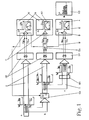
- the sequence of the measurement method according to the invention for determining small light absorptions is subdivided into three process stages a, b, c.
- preliminary stage a a basic measurement is carried out without the material MA to be examined in order to determine the actual state of the measuring arrangement.
- tuning stage b a zero deviation that may have been found in the preliminary stage a is then tuned.
- measurement stage c the actual measurement series is carried out.
- the three process stages a, b, c are shown in chronological order. Intensities I M , I R that occur are plotted over the measuring time t in small diagrams which are intended to illustrate the relationships.
- a measuring light beam M with a selected measuring wavelength ⁇ M and a basic intensity I Ma dependent on the generation source and a reference light beam R with a selected reference wavelength ⁇ R and a basic intensity I Ra likewise dependent on the generating source are used for a detection DE fed.
- measuring and reference light beams M, R can appear as individual beams or together. This is indicated in FIG. 1 by a superordinate beam path S, in which the measuring and reference light beams M, R are contained.
- the detection DE of the basic intensities I Ma and I Ra can take place quasi-simultaneously with the rapidly alternating supply of measuring and reference light beams M, R or exactly at the same time with simultaneous supply.
- the detection DE produces a measurement signal U Ma and a reference signal U Ra . These are fed to an analog common detection E.
- This common detection E takes the form of a difference D between the measurement and reference signal U Ma , U Ra .
- an intensity difference ⁇ I between the intensities I Ma , I Ra is displayed as a directly measured light absorption LA with an analog display device A.
- no light absorption LA can occur since there is no absorbent material MA in the beam path S.
- the displayed intensity difference ⁇ I is therefore a natural intensity difference ⁇ I N between the measurement and reference light beam M, R, which has its cause in the different wavelengths ⁇ m , ⁇ R and for a different weighting of the measurement and reference light beam M, R leads. If this difference ⁇ I N were not taken into account, it would falsify each measurement result, so that the values displayed on the analog display device A did not allow a quick and direct statement about the measured light absorption LA. Therefore, in the measuring method, the natural intensity difference ⁇ I N is automatically taken into account in the form of an adjustment AN of the difference formation D to zero. As a result, each subsequent measurement result displayed with the analog display device A can now be interpreted as directly measured light absorption LA without additional preparation.
- the reconciliation AN of the difference formation D to zero takes place in a reconciliation measurement in the reconciliation stage b.
- Optical zeroing OA or electronic zeroing EA can be performed. This alternative is shown in FIG. 1 by the dashed lines of action when forming the difference D in the preliminary stage a. However, only one of the two voting options is carried out, both of which achieve the same effect.
- the basic intensity I Ra of the reference light beam R is greater than the basic intensity I Ma of the measuring light beam M.
- the balancing is not carried out optically but electronically with the electronic zero adjustment EA.
- the weighting can be set, for example, by a computer-controlled change in amplification factors when forming the difference D.
- this adjustment AN can also largely compensate for matrix effects.
- a substrate disk (without an absorbing layer) or a solvent (without the substance to be analyzed), which may falsify the measurement result is introduced into the beam path S and the intensity difference ⁇ I is adjusted to zero.
- the natural difference in intensity ⁇ I N is always neutralized by its automatic consideration B in its influence on the measurement result.
- the actual measurement can now be carried out in measuring stage c.
- the material MA to be examined is introduced into the beam path S, so that the measurement and reference light beam M, R transmit.
- the measuring light beam M is optimally absorbed by the material MA due to its measuring wavelength ⁇ M , which was selected above the absorption edge or in the range of an absorption band of the material MA. Furthermore, it is weakened by additional interference, in particular reflection and scattering. Its basic intensity I Ma decreases to the transmission intensity I Mc .
- the reference light beam R has the reference wavelength ⁇ R , which is selected in the transparent spectral range of the material to be examined MA close to the measurement wavelength ⁇ M. It is therefore only insignificantly absorbed by the material MA, but is mainly subject to the interferences that occur. Its tuning intensity I Rb (with optical tuning OA; I Ra with electronic tuning EA) lowers to the transmission intensity I Rc , which is in any case even greater than the transmission intensity I Mc of the measuring light beam M.
- the subsequent detection DE then results the measurement and reference signals U Mc and U Rc (with optical tuning OA; U Ra with electronic tuning EA). These are now fed to the analog difference formation D, taking into account B the natural intensity difference ⁇ I N automatically.
- the quick and highly precise measurement result of this difference formation D as a directly measured value is the light absorption LA by the material MA to be examined. All disturbing influences were largely compensated for when forming the difference D.
- the measurement results of the light absorptions LA can then be processed, for example, in a graphical representation GD.
- the presentation can be continuous or discreet depending on the type of detection DE, as well as location-independent over the entire measuring time t or depending on the measuring location x depending on the type of material MA to be examined.
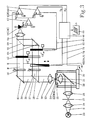
- FIG. 2 shows a particularly preferred embodiment for carrying out the measuring method in schematic form. It is characteristic of this embodiment that it has a single light source 20 and two detectors 21, 22. The detection DE thus takes place exactly at the same time.
- the material MA to be examined is a solid, the thickness of which is to be determined by measuring the light absorption LA.
- the solid is an epitaxial semiconductor chip 23 with an absorbent InGaAsP layer 24, which has grown epitaxially on a transparent InP layer 25.
- the absorbent layer 24 has a thickness between 0.01 and 2 ⁇ m
- the transparent layer 25 has a thickness of around 300 ⁇ m.
- a common beam path S is first passed through a first converging lens 26, then through a spatial filter 27 and then through a second converging lens 28 for better beam focusing.
- the spatial filter 27 represents a replacement for light sources and, with its strong diaphragm, serves to improve beam focusing for a highly precise measurement location resolution.
- a rotating chopper 29 is arranged behind the spatial filter 27 and clocks the beam path S as alternating light, in the example with a frequency f of 1 kHz.
- the beam path S falls on a deflecting mirror 30 and from there through a third converging lens 31 on the semiconductor chip 23, which is arranged on a measuring table 32 which can be moved in two directions x, y.
- a focusing point 33 lies on the upper side 24 of the semiconductor chip 23 due to the smooth rear side 25. In the case of a solid to be examined with a rough rear side, the focusing point 33 would lie on this rough rear side in order to be able to detect the scattered light as completely as possible.
- the diameter of the focusing point 33 depends on the quality of the beam path S and can be 100 ⁇ m and less with good accuracy.
- a fourth converging lens 34 for parallelizing the beam is arranged behind the semiconductor chip 23 and has a large aperture corresponding to the scattering angle of the scattered light that occurs. Behind this fourth converging lens 34, the beam path S is directed to a beam splitter 35, which splits the beam path S into two individual beams 36, 37. Because of the zero adjustment, the division ratio of the beam splitter 35 is not of interest, it is automatically taken into account.
- the measuring light beam M with the measuring wavelength ⁇ M is filtered out of the single beam 36 deflected by the beam splitter 35 using a measuring wavelength filter 38. This is chosen in accordance with the band edge of the absorbing InGaAsP layer 24 of the semiconductor chip 23 so that the measuring light beam M is absorbed to a maximum.
- the single beam 37 passing through the beam splitter 35 is passed through a reference wavelength filter 39, whereby the reference light beam R with the reference wavelength ⁇ R is selected.
- the reference wavelength ⁇ R is selected in the transparent spectral range of the InGaAsP layer 24 in the vicinity of the band edge so that the light absorption LA is only minimal. Therefore, the reference light beam R is mainly weakened by the interference effects during transmission through the semiconductor chip 23.
- the natural difference in intensity ⁇ I N (see Fig. 1) between the measurement and reference light beam M, R is automatically compensated for by an optical tuning OA.
- a variable gray filter 40 is arranged in the reference light beam R. The position of this can be changed manually using a micrometer screw or by means of a computer control.
- the reference light beam R is then passed through a fifth converging lens 41 onto the first detector 21.
- the measuring light beam M falls on the second detector 22 without further influence by a sixth converging lens 42.
- the absolutely simultaneous detection DE with the detectors 21, 22 is made possible by the arrangement described that the one light beam S is optically split and off after the material transmission the resulting individual beams 35, 36 measuring and reference light beams M, R are filtered out.
- Each of the two detectors 21, 22, which are InGaAs or Ge photodiodes in the example, is connected to an electrical preamplifier 43, 44, which converts the photocurrent generated by the detectors 21, 22 into the measurement and reference signal U M , Convert U R in the form of voltages.
- an electronic adjustment can also be carried out by computer-controlled variation of their amplification factors.
- the generated measurement and reference signals U M , U R are then fed to an analog common detection E in the form of a differential amplifier 45, which forms the signal difference ⁇ U from the analog individual signals U M , U R as a measure of the light absorption LA sought. Since this signal difference ⁇ U is very small, it can be measured with high resolution accuracy.
- the differential amplifier 45 is a first lock-in amplifier 46 with which frequency and phase-selective suppression of general interference influences can be. Only the desired measurement and reference signals U M , U R are processed by this first lock-in amplifier 46 on the basis of their alternating frequency f impressed with the chopper 29. With a second lock-in amplifier 47, the reference signal U R is measured simultaneously with the analog difference ⁇ U.
- Both measurands ⁇ U, U R are required to calculate the layer thickness.
- this calculation is carried out using a computer 48 (Atari, VME bus, Rhotron).
- the measuring table 32 and the variable gray filter 40 are also controlled with this computer 48 and a necessary calibration is carried out.
- the computer 48 can also take control of the pre-amplification factors.
- the calculated layer thicknesses are then forwarded to a plotter 49, with which a three-dimensional layer thickness mapping is produced by the semiconductor chip 23 in the example.
- a separate, direct representation of the absorption values (GD; see FIG. 1) determined analogously is not provided in this exemplary embodiment.
- FIG. 3 schematically shows an embodiment for carrying out the measuring method, which essentially differs from the exemplary embodiment in FIG. 2 in that only a single detector 60 is used.
- the detection DE thus takes place quasi-simultaneously.
- the elements that correspond to the optical structure in FIG. 2 are provided with the same reference symbols and are not explained further here.
- the first individual beam 36 is guided parallel to the second individual beam 37 by a further deflecting mirror 61.
- Measuring and reference light beam M, R are clocked together alternately with a first chopper 62 at a first frequency f1, and the reference light beam R with a second chopper 63 in one second frequency f2 additionally clocked.
- the first clocking with the frequency f1 has the effect that the measurement and reference light beam M, R are passed quickly and alternately via a further converging lens 64 to the one detector 60.
- An additional optical coupling of the reference light beam R into the beam path of the measuring light beam M is required for this purpose.
- the single detector 60 therefore detects measuring and reference light beams M, R alternately in the first frequency f1 and only the reference light beam R in the second frequency f2.
- the detected measurement and reference signals U M , U R are then fed to a single preamplifier 67. Since the signals U M , U R are only processed with one detector 60 and one preamplifier 67, a possible drift between a plurality of detectors and preamplifiers is avoided.
- the automatic consideration B of the natural intensity difference ⁇ I N takes place exclusively through the optical tuning OA. Because of the different modulation, the difference ⁇ U is then formed from the measurement and reference signal U M , U R with the first lock-in amplifier 46 and the differential amplifier 45, the first lock-in amplifier 46 being connected via a line 68 to the Frequency f1 of the first chopper 62 is correlated.
- the reference signal U R is additionally provided with the second lock-in amplifier 47.
- the second lock-in amplifier 47 is correlated with the frequency f2 of the second chopper 63 via a line 69.
- the evaluation is carried out via the computer 48.
- Control lines 70, 71 for the automatic control of the measuring table 32 and the variable gray filter 40 for optical tuning OA are also shown.
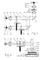
- FIG. 4 shows a section of a measuring arrangement for the method, which differs from the two previous exemplary embodiments in FIGS. 2 and 3 in the generation of measuring and reference light beams M, R.
- these are generated by filtering them out of two individual beams, which result from the optical division of a single light beam from a light source.
- measuring and reference light beams M, R are generated directly by means of two monochromatic light sources.
- these are two power-stabilized laser diodes 80, 81 with the wavelengths ⁇ M and ⁇ R selected in accordance with the material to be examined MA.
- electronic tuning EA is possible by regulating the power of the corresponding laser diode 80, 81 (not shown).
- the further beam path of the measuring and reference light beam M, R essentially corresponds to that from FIG. 3.
- the measuring and reference light beam M, R are guided via converging lenses 82, 83 for further focusing and then alternately clocked at a frequency f3 by a chopper 84 .
- the frequency f4 is also impressed on the reference light beam R with a second chopper 85. Since the laser diodes 80, 81 used also produce very stable output signals in alternating operation, the mechanical choppers 84, 85 can also be replaced by electrical modulation (not shown).
- the two laser diodes 80, 81 are switched on and off alternately.
- the reference light beam R is first passed over a deflection mirror 86 and then over a beam splitter 87.
- both beams M, R are pivoted in their direction by 90 °, for example for reasons of space, via a further deflecting mirror 88.
- a collecting lens 89.90 is again provided in front of and behind the material MA to be examined.
- the material MA to be examined is displaceable in the directions x, y by a measuring table (32; see FIG. 3), not shown.
- the detection DE is carried out by a single detector 91, which can be identical to the detector 60 from FIG. 3.
- the further structure behind the detector 91 corresponds to that in FIG. 3 and is therefore not shown here.
- the automatic consideration of the natural intensity difference I N is also not shown. This can be done in the manner already described by optical tuning (OA; see Fig. 2) by weakening the corresponding light beam in front of the chopper 84 or by electronic tuning (EA; see Fig. 2) by means of power regulation of the corresponding laser diode 80 , 81
- the section of an arrangement for carrying out the method shown in FIG. 5 essentially corresponds to the structure described in FIG. 2, the only difference being that the detection DE (only indicated in FIG. 5) is on an incident side 100 of the material to be examined MA is done. Because of the other agreement, the details already described are identified by the same reference numerals as in FIG. 2; The structure of detection, detection, tuning and evaluation, not shown in FIG. 5, is identical to that in FIG. 2 and is not explained in more detail here.
- FIG. 5 shows an incident light arrangement for a solid body. However, this arrangement can also be used, for example, for process monitoring of liquid or gaseous media. It is essential that the material to be examined MA, in the selected exemplary embodiment an absorbent layer 101 of a solid should be determined in its thickness, has a reflector 104 on its rear side 102, which is formed by a transparent substrate 103. In the example shown, this is a metal carrier firmly connected to the transparent substrate 103. However, it can also be a vapor-deposited metal contact (e.g. made of Au) or an external mirror.
- a vapor-deposited metal contact e.g. made of Au
- the beam path S is directed via a semitransparent mirror 105 onto the material MA to be examined. It is reflected on the reflector 104, then passes through the mirror 105 and is fed to the detection DE in the manner already described (FIG. 2).
- the illumination by the light source 20 and the detection DE are therefore both on the incident light side 100 of the material MA to be examined, which also means space savings.
- the measuring light beam M is weakened twice by the absorbing layer 101 and that the intensity I Rc (see FIG. 1) of the reference light beam R to be detected has two reflection components due to reflection the surface of the absorbent layer 101 and on the reflector 104.
- the reflection component on the surface of the absorbing layer 101 is unknown, this can be excluded from the detection DE by illuminating the material MA according to the dark field principle.
- the arrangement based on this principle is not shown in FIG. 5, but will be briefly explained here, since it differs from the illustrated arrangement only in details.
- the beam path S is directed onto the material MA to be examined via a very small deflecting mirror (instead of a semitransparent mirror 105).
- a large deflecting mirror with a small hole and an exchange of light source 20 and detection DE is also possible.
- the incidence of light is perpendicular to the material MA and is focused on the surface of the absorbent layer 101.
- the portion of light reflected on the surface is returned exactly in the beam path S via the small deflecting mirror to the light source 20. It does not get into the detection beam path.
- parallel light beams strike the material MA to be examined, for example by arranging the small deflecting mirror between the fourth converging lens 34 and the material MA to be examined.
- the light component passing through the absorbing and transparent layers 101, 103 is reflected on the reflector 104. This is opaque, so that the light component is reflected in a large solid angle (the same effect is also caused by a rough, scattering back of the material to be examined MA).
- the reflected light is then detected by the fourth converging lens 34, which has a correspondingly large aperture, and is guided past the small deflecting mirror into the detection beam path for detection DE. Then again when evaluating to take into account the double absorption of the detected light component.
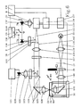
- FIG. 6 shows an arrangement example for the combination of the measurement method for small light absorptions with the luminescence method known per se.
- this method is only explained in principle in order to establish the connection, essential for the invention is the coupling of the two methods, which is a clear improvement with regard to the course and duration of the method by adjusting the material to be examined MA only once and by assigning the material parameters measured with the two methods at identical sample points.
- the reference symbols used in FIG. 2, insofar as the arrangement parts are identical, are adopted.
- the luminescence method is used to determine characteristic properties of semiconductor materials, in particular the band edge (absorption edge).
- the band edge In technologically important mixed crystals such as InGaAsP or GaAlAs, the band edge can be adjusted using the mixing ratio.
- the band edge is one of the most important design parameters in optoelectronic components. This parameter can be determined from luminescence emission spectra. It is important for the measuring method for the determination of small light absorptions that the measuring wavelength is optimally chosen from knowledge of the band edge and that the absorption coefficient of the layer to be examined in each case can be derived at this measuring wavelength.
- the absorbing layer 24 of the material to be examined MA is irradiated with monochromatic light from a laser diode 120, which is fed from a power supply 121.
- the beam path S of the light runs through a first converging lens 122, a color filter 123 for filtering out background interference, a dichroic one Mirror 124, a deflecting mirror 125 and a second converging lens 126.
- the material MA is excited by the light to emit characteristic radiation (luminescence effect). This emitted luminescence radiation is in turn fed to the dichroic mirror 124 via the deflection mirror 125. This has the property that it either reflects or lets light pass depending on its wavelength.
- the luminescence radiation is imaged with a third converging lens 128 into a tunable monochromator 129.
- the wavelength of the monochromator 129 is varied with a motorized adjustment 130.
- the spectrally selected light is imaged behind the monochromator 129 with a fourth converging lens 131 onto a detector 132 and the emission spectrum is recorded with it.
- a second deflection mirror 133 can be introduced into the beam path S in front of the monochromator 129 and the integral luminescence - an important measure of the crystal quality - can thus be measured with a further detector 134.
- the signals from the detectors 132, 134 are fed to differential inputs of a lock-in amplifier 135, the detector 132, 134 not required in each case being short-circuited via a switch 136.
- the control of the wavelength adjustment 130 and the measuring table 32 via a stepper motor 137 are carried out by a computer 138. This is also used for evaluation.
- the measuring method for determining small light absorptions LA is now coupled into the described structure for the luminescence measuring method as follows:
- the beam path S emanating from the light source 20 is initially already in Described way on an arrangement of fifth lens 139, spatial filter 27, chopper 29 and sixth lens 140 directed to a third deflection mirror 141.
- This directs the beam path S via a seventh converging lens 142 onto the material MA to be examined.
- the beam path S is guided through the second converging lens 126, the deflecting mirror 125, the dichroic mirror 124, which in the example shown does not allow only the wavelength of the light from the laser diode 120 to pass through, the color filter 127 and the third converging lens 128.
- a beam splitter 143 is now introduced into the beam path. This splits the light beam S into a first partial light beam 144 and a second partial light beam 145. The reflected first partial light beam 144 is then filtered by the now inserted reference wavelength filter 39, so that the reference light beam R is created.
- the monochromator 129 is set to the measuring wavelength ⁇ M , and the measuring light beam M is filtered out of the second partial light beam 130. Measuring and reference light beam M, R are then detected simultaneously with detectors 132 and 134, and measuring and reference signal U M , U R are fed to difference formation D.
- the switch 136 is in a zero position and does not short either of the two detectors 132, 134. To obtain the reference signal U R , the detector 132 can either be short-circuited for a short time via the switch 136 or the reference signal U R is passed in parallel to a second lock-in amplifier (not shown) in order to achieve a high measuring speed.
- Differential signal ⁇ U and reference signal U R are - as already stated - necessary to calculate the layer thickness of the material to be examined MA from the measured small light absorptions.
- the automatic consideration B of the natural intensity difference ⁇ I N required for the direct measurement of the small light absorptions takes place in the arrangement shown for the coupled Execution of both measuring methods by the electronic coordination EA when forming the difference D.
Landscapes
- Physics & Mathematics (AREA)
- Health & Medical Sciences (AREA)
- Spectroscopy & Molecular Physics (AREA)
- General Physics & Mathematics (AREA)
- General Health & Medical Sciences (AREA)
- Biochemistry (AREA)
- Analytical Chemistry (AREA)
- Chemical & Material Sciences (AREA)
- Immunology (AREA)
- Pathology (AREA)
- Life Sciences & Earth Sciences (AREA)
- Toxicology (AREA)
- Investigating Or Analysing Materials By Optical Means (AREA)
- Investigating, Analyzing Materials By Fluorescence Or Luminescence (AREA)
Abstract
Description
Die Erfindung bezieht sich auf ein Meßverfahren zur Bestimmung kleiner Lichtabsorptionen in beliebigen Materialien mit einer zumindest quasi-gleichzeitigen Detektion der Transmissionsintensitäten eines Meß- und eines Referenzlichtstrahls derart unterschiedlicher Wellenlängen, daß im wesentlichen der Meßlichtstrahl von dem zu untersuchenden Material absorbiert wird, und mit einer analogen gemeinsamen Erfassung der detektierten Meß- und Referenzsignale unter Berücksichtigung des natürlichen Intensitätsunterschieds zwischen Meß- und Referenzlichtstrahl.The invention relates to a measuring method for determining small light absorptions in any materials with at least quasi-simultaneous detection of the transmission intensities of a measuring and a reference light beam of such different wavelengths that the measuring light beam is essentially absorbed by the material to be examined, and with an analog joint detection of the detected measurement and reference signals, taking into account the natural difference in intensity between the measurement and reference light beam.
Durch den Einsatz von Meß- und Referenzlichtstrahl mit unterschiedlichen Wellenlängen können Störeinflüsse, die sich als systematische Fehler auf das Meßergebnis auswirken, weitgehend eliminiert werden. Dazu wird die Wellenlänge des Meßlichtstrahls so gewählt, daß dieser optimal von dem zu untersuchenden Material absorbiert wird. Optimale Absorption tritt bei Festkörpern, Flüssigkeiten und Gasen im Bereich charakteristischer Absorptionsbanden auf, sowie in Festkörpern oberhalb der Bandkante. Die Absorptionsfähigkeit eines Materials ist also stark von der Wellenlänge des transmittierenden Lichtstrahls abhängig. Zusätzlich wird der Meßlichtstrahl bei der Transmission durch das zu untersuchende Material noch von Störeinflüssen wie beispielsweise Reflexion, Streuung, Verschmutzung oder zusätzliche Absorption durch andere Medien geschwächt. Solche Störeinflüsse haben als generelle Verluste meist einen breiten Untergrund, weil sie nur eine schwache Abhängigkeit von der Wellenlänge haben. Die Wellenlänge des Referenzlichtstrahls wird der Meßwellenlänge benachbart, aber im transparenten Spektralbereich des zu untersuchenden Materials gewählt. Der Referenzlichtstrahl wird deshalb kaum absorbiert, sondern im wesentlichen nur von den Störeinflüssen geschwächt. Mit dem Referenzlichtstrahl wird also die Transmissionsintensität ohne Absorption ermittelt, mit dem Meßlichtstrahl dagegen die Transmissionsintensität mit Absorption. Bei der gemeinsamen Erfassung der detektierten Meß- und Referenzsignale ist die relative Intensitätsschwächung durch Störeinflüsse in beiden Lichtstrahlen weitgehend identisch. Korrigiert man die Signale bezüglich des natürlichen Intensitätsunterschieds zwischen den beiden Wellenlängen, so verbleibt nur die Intensitätsdifferenz, die physikalisch der Lichtabsorption des zu untersuchenden Materials entspricht.By using measuring and reference light beams with different wavelengths, disturbances that have a systematic error on the measurement result can be largely eliminated. For this purpose, the wavelength of the measuring light beam is selected so that it is optimally absorbed by the material to be examined. Optimal absorption occurs with solids, liquids and gases in the area of characteristic absorption bands, as well as in solids above the band edge. The absorptivity of a material is therefore strongly dependent on the wavelength of the transmitting light beam. In addition, the measuring light beam during transmission through the material to be examined is also influenced by interference, for example Reflection, scattering, pollution or additional absorption weakened by other media. Such interferences usually have a broad background as general losses because they have only a weak dependence on the wavelength. The wavelength of the reference light beam is adjacent to the measuring wavelength, but is selected in the transparent spectral range of the material to be examined. The reference light beam is therefore hardly absorbed, but essentially only weakened by the interference. The transmission intensity without absorption is thus determined with the reference light beam, whereas the transmission intensity with absorption is determined with the measurement light beam. When the detected measurement and reference signals are recorded jointly, the relative intensity attenuation due to interference in both light beams is largely identical. If one corrects the signals with regard to the natural difference in intensity between the two wavelengths, only the difference in intensity remains which physically corresponds to the light absorption of the material to be examined.
Ein wie zuvor beschriebenes Meßverfahren ist aus dem Prospekt "Transmissions Photometer" der Firma Pier Electronic GmbH, Nassaustraße 35, D-6238 Hofheim-Wallau, bekannt. Mit diesem Verfahren werden kleine Lichtabsorptionen durch eine analoge gemeinsame Erfassung von mit hoher Wechselfrequenz alternierend detektierten Meß- und Referenzsignalen in Form ihres Quotienten bestimmt. Die Berücksichtigung des natürlichen Intensitätsunterschieds zwischen Meß- und Referenzlichtstrahl erfolgt durch rechnerische Einbeziehung eines Intensitäts-Quotienten beider Lichtstrahlen ohne Absorption durch das zu untersuchende Material. Die Lichtabsorptionen werden bei diesem bekannten Verfahren also indirekt bestimmt, da der ermittelte Quotient kein direktes Maß für die Lichtabsorption ist. Diese berechnet sich erst aus der Differenz der Zahl 1 zu dem Quotienten. Mit dieser Umrechnung ist jedoch eine verstärkte Fehlerfortpflanzung verbunden. Bei kleinen Absorptionen führen nämlich relativ starke Änderungen der Lichtabsorption (z.B. von 1% auf 2%, d.h. relativ um 100%) nur zu kleinen Änderungen des Quotienten (z.B. von 0,99 auf 0,98, d.h. relativ um 1%). Selbst kleine Meßfehler oder Digitalisierungssprünge bewirken somit eine sehr viel größere Ungenauigkeit bei der Bestimmung der Lichtabsorption. Insbesondere bei kleinen Lichtabsorptionen kann der Fehler daher ohne weiteres die Größenordnung der Absorption annehmen oder überschreiten.A measurement method as described above is known from the "Transmissions Photometer" brochure from Pier Electronic GmbH, Nassaustrasse 35, D-6238 Hofheim-Wallau. With this method, small light absorptions are determined in the form of their quotient by an analog common detection of measurement and reference signals alternately detected with a high alternating frequency. The natural difference in intensity between the measurement and reference light beam is taken into account by mathematically including an intensity quotient of both light beams without absorption by the material to be examined. With this known method, the light absorptions are thus determined indirectly, since the quotient determined is not a direct measure of the light absorption. This is calculated from the difference between the
In der Weiterentwicklung der Technik wird es bei vielen Anwendungsfällen des beschriebenen Meßverfahrens immer wichtiger, auch kleine Lichtabsorptionen hochgenau messen zu können. Hiermit im Zusammenhang steht auch das Bestreben, die Lichtabsorption sehr schnell zu messen. Darüberhinaus soll ein Meßverfahren in seinem Ablauf und in seinen Mitteln zur Durchführung stets einfach und damit ökonomisch sein.In the further development of technology, it is becoming increasingly important for many applications of the measurement method described to be able to measure even small light absorptions with high precision. In connection with this is also the effort to measure light absorption very quickly. In addition, a measuring method should always be simple and therefore economical in its execution and in its means of implementation.
Derart hohe Anforderungen erfüllt das Meßverfahren nach der vorliegenden Erfindung dadurch, daß die kleinen Lichtabsorptionen direkt gemessen werden durch die gemeinsame Erfassung der detektierten Meß- und Referenzsignale in Form einer Differenzbildung unter automatischer Berücksichtigung des natürlichen Intensitätsunterschieds zwischen Meß- und Referenzlichtstrahl durch eine Abstimmung der gebildeten Differenz auf Null bei einer Messung ohne das zu untersuchende Material.The measurement method according to the present invention fulfills such high requirements in that the small light absorptions are measured directly by the joint detection of the detected measurement and reference signals in the form of a difference, taking into account the natural difference in intensity between the measurement and reference light beam by coordinating the difference formed to zero for a measurement without the material to be examined.
Durch die direkte Messung der Lichtabsorptionen ist das erfindungsgemäße Meßverfahren sehr genau und schnell. Die Messung kann als direkt bezeichnet werden, weil die analog gebildete Differenz zwischen Meß- und Referenzsignal die physikalische Definition der Absorption realisiert. Durch die automatische Berücksichtigung des natürlichen Intensitätsunterschieds steht damit ohne weiteren Rechen- und Zeitaufwand in einfacher Weise direkt der Meßwert für die gesuchte Lichtabsorption zur Verfügung. Verbunden mit der dadurch erreichten hohen Meßgeschwindigkeit ist eine hohe Meßauflösung, da der Auflösungsbereich nur die Größenordnung der Differenz und nicht die um ein Vielfaches größere Größenordnung der Einzelgrößen umfaßt. Eine erhebliche Verbesserung der Meßgenauigkeit wird bei dem erfindungsgemäßen Meßverfahren dadurch erreicht, daß der bei der direkten Differenzbildung eingehende meßtechnische Fehler nicht verstärkt wird. Das bedeutet, daß sich der absolute meßtechnische Fehler zu kleineren Lichtabsorptionen hin ebenfalls verkleinert, der entscheidende relative Fehler aber nahezu unverändert bleibt. Der Einfluß von Störgrößen, die nur schwach wellenlängenabhängig sind, wird durch die Differenzbildung ebenfalls derart verkleinert, daß er unerheblich wird. Zeitliche Schwankungen der Lichtquellen und der Auswerteelektronik werden bei dieser Art der direkten Differenzbildung weitgehend kompensiert.Due to the direct measurement of the light absorptions, the measuring method according to the invention is very precise and fast. The measurement can be described as direct, because the analog difference between the measurement and reference signal realizes the physical definition of the absorption. Due to the automatic consideration of the natural difference in intensity, there is no further calculation and time expenditure the measured value for the desired light absorption is available in a simple manner. Associated with the high measurement speed achieved thereby is a high measurement resolution, since the resolution range only includes the order of magnitude of the difference and not the order of magnitude of the individual sizes, which is many times larger. A considerable improvement in the measuring accuracy is achieved in the measuring method according to the invention in that the metrological errors involved in the direct formation of the difference are not amplified. This means that the absolute measurement error also decreases towards smaller light absorptions, but the decisive relative error remains almost unchanged. The influence of disturbance variables that are only weakly wavelength-dependent is also reduced by the difference formation in such a way that it becomes insignificant. Fluctuations in time of the light sources and the evaluation electronics are largely compensated for in this type of direct difference formation.
Es ist zwar aus dem Aufsatz "Direct observation of the principal deep level (EL2) in undoped semiinsulating GaAs", Brozel et al., Appl.Phys.Lett 42(7), 1 April 1983, Seiten 610 ff, bekannt, aus den detektierten Meß- und Referenzsignalen eine Differenz zu bilden. Diese Differenz wird jedoch mathematisch berechnet. Dazu werden die Meß- und Referenzsignale einzeln, zeitlich versetzt digital erfaßt. Der dabei auftretende relative Fehler bezieht sich auf die erfaßten großen Einzelwerte. Er ist daher entscheidend größer als der relative Fehler, der bei der direkten Messung der wesentlich kleineren Differenz gemacht wird. Außerdem treten Sprungfehler bei der Digitalisierung auf. Weiterhin werden die Meß- und Referenzsignale in einem zeitlich großen Abstand zueinander detektiert, so daß der Meß- und Referenzlichtstrahl und die Auswerteelektronik zeitlich sehr stabil sein müssen. Die Meßergebnisse stehen erst nach Vorliegen aller Einzelsignale und deren rechnerischer Verabeitung zur Verfügung.It is known from the article "Direct observation of the principal deep level (EL2) in undoped semiinsulating GaAs", Brozel et al., Appl.Phys.Lett 42 (7), April 1, 1983, pages 610 ff detected measurement and reference signals to form a difference. However, this difference is calculated mathematically. For this purpose, the measurement and reference signals are digitally recorded individually at different times. The relative error that occurs relates to the large individual values recorded. It is therefore significantly larger than the relative error that is made in the direct measurement of the much smaller difference. Jump errors also occur in digitization. Furthermore, the measurement and reference signals are detected at a large time interval from one another, so that the measurement and reference light beam and the evaluation electronics must be very stable over time. The measurement results are only available after all individual signals have been received and their processing has been carried out.
Eine direkte Messung der Lichtabsorption bzw. der Intensitätsdifferenz mittels einer analogen gemeinsamen Erfassung der detektierten Meß- und Referenzsignale ist aus dem Aufsatz "Experimental requirements for quantitative mapping of midgap flaw concentration in semi-insulating GaAs wafers by measurement of near infrared transmittance", Dobrilla et al., J.Appl. Phys. 58(1), 1 July 1985, Seiten 208 ff, bekannt. Bei diesem Meßverfahren wird zunächst an einem Referenzpunkt auf dem zu untersuchenden Material die Lichtabsorption mit hohem Aufwand genau bestimmt und elektronisch kompensiert. Bei den anschließenden Messungen wird dann die relative Lichtabsorption als Differenz zu der Absorption im Referenzpunkt direkt gemessen. Meß- und Referenzlichtstrahl haben jedoch die gleiche Wellenlänge. Reflexionsverluste als systematische Fehler werden deshalb mathematisch unter Inkaufnahme einer entsprechenden Diskrepanz zur Realität und eines großen Zeitaufwandes berücksichtigt. Streuverluste werden nicht berücksichtigt. Die Detektion von Meß- und Referenzlichtstrahl erfolgt in zeitlich großem Abstand; der Meßlichtstrahl, das Kompensationssignal und die Auswerteelektronik müssen entsprechend zeitstabil sein.A direct measurement of the light absorption or the intensity difference by means of an analog joint detection of the detected measurement and reference signals is from the article "Experimental requirements for quantitative mapping of midgap flaw concentration in semi-insulating GaAs wafers by measurement of near infrared transmittance", Dobrilla et al., J.Appl. Phys. 58 (1), 1 July 1985, pages 208 ff. In this measuring method, the light absorption is first determined with great effort and electronically compensated at a reference point on the material to be examined. In the subsequent measurements, the relative light absorption is then measured directly as the difference to the absorption at the reference point. However, the measuring and reference light beams have the same wavelength. Loss of reflection as a systematic error is therefore taken into account mathematically while accepting a corresponding discrepancy to reality and a large expenditure of time. Scattering losses are not taken into account. The measurement and reference light beam are detected at a large time interval; the measuring light beam, the compensation signal and the evaluation electronics must be time stable accordingly.
Trotz seiner hohen Meßgenauigkeit und -schnelligkeit ist das erfindungsgemäße Meßverfahren in seinem Ablauf und in seiner Realisierung einfach. Diese Einfachheit wird neben der unkomplizierten direkten Differenzbildung besonders durch die automatische Berücksichtigung des natürlichen Intensitätsunterschieds bei der Differenzbildung erreicht. Berücksichtigt werden muß der Intensitätsunterschied, um in der gebildeten Differenz ein direkt verwertbares Ergebnis zu haben, das unabhängig von den natürlichen, unterschiedlichen Intensitäten von Meß- und Referenzlichtstrahl aufgrund ihrer unterschiedlichen Wellenlängen ist. Gegenüber der rechnerischen Berücksichtigung im Stand der Technik erfolgt diese beim erfindungsgemäßen Verfahren automatisch. Dazu ist es lediglich erforderlich, die gemessene Differenz vor Beginn einer Meßreihe ohne das zu untersuchende Material auf Null einzuregeln. Die Kenntnis der einzelnen Parameter durch deren Messung oder Berechnung ist dazu nicht erforderlich. Diese Nullabstimmung gleicht den natürlichen Intensitätsunterschied zwischen Meß- und Referenzlichtstrahl aus, so daß alle Störparameter nahezu den gleichen Einfluß haben. Nur durch diesen Abgleich, durch den damit alle auftretenden Störgrößen im wesentlichen, d.h. bis auf eine geringe Differenz aufgrund ihrer sehr schwachen Wellenlängenabhängigkeit, bei der Differenzbildung eliminiert werden, wird die direkte Messung der Differenz bzw. Lichtabsorption überhaupt möglich und sinnvoll. Weiterhin können durch die Nullabstimmung auch Matrix-Effekte durch Umgebungseinflüsse weitgehend berücksichtigt werden.Despite its high measuring accuracy and speed, the measuring method according to the invention is simple in its sequence and in its implementation. In addition to the straightforward direct difference formation, this simplicity is achieved in particular by automatically taking the natural intensity difference into account when forming the difference. The difference in intensity must be taken into account in order to have a directly usable result in the difference formed, which is independent of the natural, different intensities of the measurement and reference light beam due to their different wavelengths. Compared to the mathematical consideration in the prior art, this takes place automatically in the method according to the invention. It is for that it is only necessary to adjust the measured difference before the start of a series of measurements without zeroing the material to be examined. Knowledge of the individual parameters through their measurement or calculation is not necessary for this. This zero adjustment compensates for the natural difference in intensity between the measuring and reference light beams, so that all interference parameters have almost the same influence. It is only through this comparison, by means of which all the disturbance variables that occur are essentially eliminated, ie apart from a small difference due to their very weak wavelength dependency, when the difference is formed, is it possible to directly measure the difference or light absorption at all. Furthermore, due to the zero adjustment, matrix effects due to environmental influences can also be largely taken into account.
Entsprechend einer vorteilhaften Ausgestaltung des erfindungsgemäßen Meßverfahrens kann eine Abstimmung der gebildeten Differenz auf Null optisch durch Schwächung der Intensität des stärkeren der beiden Lichtstrahlen erfolgen. Ein solcher Verfahrensschritt ist sehr einfach und erfordert nur ein unkompliziertes Verstellen beispielsweise eines Graukeils im entsprechenden Strahlengang. Bei dieser Ausführungsform wird die Reproduzierbarkeit der Graueinstellung beispielsweise über die Stellung einer Mikrometerschraube erreicht.According to an advantageous embodiment of the measuring method according to the invention, the difference formed can be optically tuned to zero by weakening the intensity of the stronger of the two light beams. Such a method step is very simple and only requires an uncomplicated adjustment, for example of a gray wedge, in the corresponding beam path. In this embodiment, the reproducibility of the gray setting is achieved, for example, by the position of a micrometer screw.
Eleganter, aber ebenso einfach mit demselben Effekt ist eine andere erfindungsgemäße Ausgestaltung, nach der die Abstimmung der gebildeten Differenz auf Null elektronisch durch Einstellen einer entsprechenden Gewichtung bei der Differenzbildung erfolgt. Bei dieser Ausführungsform kann die Nullabstimmung beispielsweise durch einen Rechner sehr genau durch die digitale Veränderung von Verstärkungsfaktoren vor der Differenzbildung über eine steuerbare Widerstandskaskade erfolgen. Die exakte Reproduzierbarkeit und eine ständige Kontrollmöglichkeit der Nullabstimmung sind damit gewährleistet. Es können keine mechanischen Justageprobleme und damit verbundene Losen auftreten. Die Nullabstimmung ist sehr zeitstabil.Another refinement according to the invention is more elegant, but just as simple, with the same effect, according to which the difference formed is adjusted electronically to zero by setting a corresponding weighting when forming the difference. In this embodiment, the zero adjustment can be carried out very precisely, for example by a computer, by digitally changing gain factors before the difference is formed via a controllable resistor cascade. The exact reproducibility and a constant The possibility of checking the zero vote is guaranteed. There can be no mechanical adjustment problems and the associated loose parts. Zeroing is very time-stable.
Beide beschriebenen Nullabstimmungs-Methoden erfolgen direkt im Meßaufbau, d.h. sie haben einen engen Bezug zu dem Meßverfahren selbst, im Gegensatz zu beispielsweise einem rechnerischen Abgleich durch eine vorgegebene Kennlinie, der von dem eigentlichen Verfahren losgelöst wäre.Both described zeroing methods take place directly in the measurement setup, i.e. they are closely related to the measuring method itself, in contrast to, for example, a mathematical comparison using a predetermined characteristic curve that would be detached from the actual method.
Nach einer anderen Ausgestaltung des erfindungsgemäßen Verfahrens werden Meß- und Referenzlichtstrahl jeweils von einer monochromatischen Lichtquelle erzeugt. Mögliche Lichtquellen sind beispielsweise Laserdioden. Diese gewährleisten aufgrund ihres geringen Strahldurchmessers eine hohe Ortsauflösung. Durch eine entsprechende optische Anordnung können die beiden Lichtstrahlen in einem Strahlengang in schnellem zeitlichem Wechsel durch das zu untersuchende Material geschickt werden. Die Abwechslung zwischen Meß- und Referenzlichtstrahl kann mechanisch durch einen Chopper oder elektrisch durch eine Modulation der Laserdioden erfolgen. Im ersten Fall wird immer ein Lichtstrahl verdeckt, im zweiten Fall werden die beiden Laserdioden im Wechselstrombetrieb gesteuert. In beiden Fällen kann eine Rechnersteuerung eingesetzt werden.According to another embodiment of the method according to the invention, the measuring and reference light beams are each generated by a monochromatic light source. Possible light sources are, for example, laser diodes. Due to their small beam diameter, these ensure a high spatial resolution. By means of an appropriate optical arrangement, the two light beams can be sent through the material to be examined in a rapid change of time in one beam path. The alternation between measuring and reference light beam can be done mechanically by a chopper or electrically by modulating the laser diodes. In the first case a light beam is always covered, in the second case the two laser diodes are controlled in AC operation. A computer control can be used in both cases.
Aus dem Aufsatz "Active layer thickness measurement system for double heterostructure laser wafers", Nakano et al., OPTICAL ENGINEERING, January 1989, Vol. 28 No. 1, Seiten 042 ff, ist zwar zur Bestimmung der Netto-Absorption in Laser-Substraten der Einsatz zweier Laserdioden bekannt. Diese werden jedoch zeitlich in einem sehr großen Abstand nacheinander betrieben, d.h. das zu untersuchende Material wird zunächst komplett mit dem Meßlichtstrahl und dann mit dem Referenzlichtstrahl abgetastet. Dieses bedeutet einen hohen Zeitversatz der Einzelmessungen bei entsprechender Meßdauer.From the article "Active layer thickness measurement system for double heterostructure laser wafers", Nakano et al., OPTICAL ENGINEERING, January 1989, vol. 28 no. 1, pages 042 ff, the use of two laser diodes is known for determining the net absorption in laser substrates. However, these are operated one after the other at a very large interval, ie the material to be examined is first scanned completely with the measuring light beam and then with the reference light beam. This means a high time offset of the individual measurements with a corresponding measurement duration.
Eine sehr gute Stabilisierung der Laserdioden zur Vermeidung von Leistungs- oder Temperaturdrift ist deshalb erforderlich. Ein Leistungsabgleich der beiden Laserdioden ist bei diesem bekannten Meßverfahren nicht vorgesehen. Das Leistungsverhältnis der beiden Laserdioden ohne Absorption wird eingerechnet. Die Meßergebnisse werden von einem Rechner ermittelt und liegen erst nach Beendigung des zweiten Abtastdurchgangs als Quotienten vor. Neben dem bereits erwähnten großen Fehlereinfluß bei der Bestimmung kleiner Lichtabsorption über Quotientenbildung aus Einzelwerten sind aufgrund der zeitlich weit auseinanderliegenden Meßdurchgänge mit zweimaligem Abrastern des zu untersuchenden Materials auch Justageprobleme zur Erreichung eines jeweils identischen Meßorts zu beherrschen.A very good stabilization of the laser diodes to avoid power or temperature drift is therefore necessary. Power matching of the two laser diodes is not provided in this known measuring method. The power ratio of the two laser diodes without absorption is included. The measurement results are determined by a computer and are available as quotients only after the second scanning pass has ended. In addition to the large error influence already mentioned in the determination of small light absorption by forming quotients from individual values, adjustment problems to achieve an identical measuring location must also be mastered due to the temporally far apart measuring passes with two scanning of the material to be examined.
Nach einer weiteren Ausgestaltung des erfindungsgemäßen Meßverfahrens ist es vorteilhaft, wenn Meß- und Referenzlichtstrahl aus einem nach der Material-Transmission optisch geteilten Lichtstrahl einer einzigen Lichtquelle herausgefiltert werden. Durch diesen Verfahrensschritt ist gewährleistet, daß der Meß- und der Referenzlichtstrahl im exakt gleichen Strahlengang, nämlich dem Strahlengang des gemeinsamen Lichtstrahls, durch das zu untersuchende Material hindurchtreten. Der Meßort ist damit genau definiert und für beide Strahlen identisch. Aufwendige Justagen zur Strahlüberdeckung am Meßort und im weiteren Strahlengang, ein Verschieben des zu untersuchenden Materials oder optische Strahlumlenkeinrichtungen sind so vermieden. Weiterhin wirken sich Schwankungen der Intensität der einzigen Lichtquelle auf Meß- und Referenzlichtstrahl gleich aus, so daß diese bei der Differenzbildung mit automatischer Berücksichtigung des natürlichen Intensitätsunterschieds kompensiert werden. Erfindungsgemäß wird der Lichtstrahl erst nach der Material-Transmission optisch geteilt, damit aus den entstandenen Einzelstrahlen der Meß- und der Referenzlichtstrahl herausgefiltert werden können. Bei der optischen Teilung ist es dabei unerheblich, in welchem Verhältnis der Lichtstrahl aufgeteilt wird, da dieses bei der Differenzbildung durch die zuvor durchgeführte Nullabstimmung bei unverändertem Teilungsverhältnis durch die dadurch erfolgende Symmetrierung der beiden Lichtstrahlen automatisch berücksichtigt wird. Die Ermittlung der Lichtabsorption als prozentuale Größe wird davon in ihrer Genauigkeit nicht beeinflußt. Es ist nicht einmal von Interesse, das Teilungsverhältnis zu kennen, es kann beliebig sein, so daß sich für die Realisierung der Teilung äußerst einfache Bauelemente verwenden lassen.According to a further embodiment of the measuring method according to the invention, it is advantageous if the measuring and reference light beam are filtered out of a light beam from a single light source that is optically divided according to the material transmission. This method step ensures that the measuring and reference light beams pass through the material to be examined in the exact same beam path, namely the beam path of the common light beam. The measuring location is thus precisely defined and identical for both beams. Complex adjustments to cover the beam at the measuring location and in the further beam path, shifting the material to be examined or optical beam deflection devices are thus avoided. Furthermore, fluctuations in the intensity of the single light source have the same effect on the measurement and reference light beam, so that these are compensated for when the difference is formed by automatically taking into account the natural difference in intensity. According to the invention, the light beam is only optically divided after the material transmission, so that the measurement and reference light beams can be filtered out of the individual beams produced. It is with the optical division the ratio in which the light beam is divided is irrelevant, since this is automatically taken into account in the difference formation by the previously carried out zero adjustment with an unchanged division ratio by the resulting symmetry of the two light beams. The determination of the light absorption as a percentage is not affected in its accuracy. It is not even of interest to know the division ratio, it can be arbitrary, so that extremely simple components can be used for the realization of the division.
Wenn gemäß einer weiteren vorteilhaften Ausgestaltung des erfindungsgemäßen Verfahrens Meß- und Referenzlichtstrahl alternierend in einer ersten und der Referenzlichtstrahl zusätzlich in einer zweiten Frequenz getaktet werden, kann für die analoge Erfassung der Meß- und Referenzsignale die allgemein bekannte Lock-In-Verstärkungstechnik eingesetzt werden. Hiermit ist man in der Lage, die detektierten Signale aufgrund der ihnen künstlich aufgeprägten Frequenzen zu unterscheiden. Ein derartiger Verfahrensschritt ist immer dann sinnvoll, wenn die Meß- und Referenzsignale durch einen einzigen Detektor erzeugt werden. Es können somit bei dem Einsatz von zwei Frequenzen gemäß der Erfindung zum einen die Meß- und Referenzsignale für die Differenzbildung und zum anderen zusätzlich zum Beispiel nur die Referenzsignale für Normie-rungszwecke erfaßt und verarbeitet werden. Außerdem können weitere Störeinflüsse, insbesondere allgemeine Hintergrundstörungen, wie Raumlicht oder Staub im Strahlengang, mit der Lock-In-Verstärkungstechnik eliminiert werden. Es werden dazu nur die Signale bearbeitet, die den zuvor bestimmten Frequenzen und auch Phasen zugeordnet sind. Störungen mit anderen Frequenzen und anderen Phasen werden nicht berücksichtigt.If, according to a further advantageous embodiment of the method according to the invention, the measurement and reference light beam are clocked alternately in a first and the reference light beam additionally in a second frequency, the generally known lock-in amplification technique can be used for the analog detection of the measurement and reference signals. This enables you to distinguish the detected signals based on the frequencies that are artificially impressed on them. Such a method step is always useful if the measurement and reference signals are generated by a single detector. Thus, when using two frequencies according to the invention, on the one hand the measurement and reference signals for forming the difference and on the other hand, for example, only the reference signals for standardization purposes can be detected and processed. In addition, other interferences, in particular general background disturbances, such as room light or dust in the beam path, can be eliminated with the lock-in amplification technology. For this purpose, only the signals are processed that are assigned to the previously determined frequencies and phases. Interferences with other frequencies and other phases are not taken into account.
Wenn Meß- und Referenzlichtstrahl aus einem einzigen Lichtstrahl herausgefiltert werden, ist es entsprechend einer weiteren vorteilhaften Ausgestaltung des erfindungsgemäßen Verfahrens sinnvoll, daß der gemeinsame Lichtstrahl getaktet wird. Hierbei kann dann wiederum die Lock-In-Verstärkungstechnik mit ihren bereits genannten Vorteilen eingesetzt werden. Da nur eine Frequenz benutzt wird, kann die Zeitkonstante des Lock-In-Verstärkers sehr klein gewählt werden, was zu kurzen Einstellzeiten und daher hoher Meßgeschwindigkeit führt. Zur Unterscheidung der Meß- und Referenzsignale zur Differenzbildung und zu Normierungszwecken werden hierbei zwei Detektoren eingesetzt, bei denen es sich um einfache elektronische Bauteile handelt.If the measuring and reference light beam are filtered out of a single light beam, it is correspondingly one Another advantageous embodiment of the method according to the invention makes sense that the common light beam is clocked. Here again the lock-in amplification technology can be used with its advantages already mentioned. Since only one frequency is used, the time constant of the lock-in amplifier can be chosen to be very small, which leads to short response times and therefore a high measuring speed. To distinguish between the measurement and reference signals for difference formation and for standardization purposes, two detectors are used, which are simple electronic components.
Eine andere, sehr wichtige vorteihafte Weiterbildung des erfindungsgemäßen Meßverfahrens sieht vor, daß die Detektion der Transmissionsintensitäten von Meß- und Referenzlichtstrahl gleichzeitig erfolgt. Durch diesen Schritt von der Quasi-Gleichzeitigkeit der Detektion im Stand der Technik zur echten Gleichzeitigkeit entfallen zunächst zeitabhängige Störeinflüsse, wie Kennlinien- und Temperaturdrift der Lichtquellen, der Detektoren oder der Auswerteeinheit. Darüberhinaus wird aber auch die Meßgeschwindigkeit erhöht, da kein Signal bis zum Eintreffen eines weiteren Signals mehr zwischengespeichert werden muß. Deshalb werden auch die mit der Zwischenspeicherung verknüpften Fehler vermieden. Mit dem Wegfall der Zwischenspeicherung aufgrund der gleichzeitigen Detektion ist auch die Möglichkeit verbunden, kontinuierliche Meßreihen aus den analog erfaßten Meßwerten bilden zu können. Die Diskretisierung der Meßwerte aufgrund der Zwischenspeicherung entfällt. Das zu untersuchende Material kann also nach dieser Ausgestaltung des erfindungsgemäßen Verfahrens kontinuierlich, beispielsweise in einem Massenstrom oder über eine Oberfläche, auf sein Absorptionsverhalten hin, welches sich auch zeitlich extrem schnell ändern kann, untersucht werden. Voraussetzung für eine gleichzeitige Detektion ist, daß Meß- und Referenzlichtstrahl nach Durchtritt durch das zu untersuchende Material gleichzeitig vorliegen, um parallel auf zwei Detektoren geleitet werden zu können. Diese Voraussetzung wird durch die oben beschriebene erfindungsgemäße Ausgestaltung in einfacher Weise erfüllt, indem Meß- und Referenzlichtstrahl aus einem einzigen Lichtstrahl nach dessen Teilung herausgefiltert werden.Another, very important, advantageous development of the measuring method according to the invention provides that the transmission intensities of the measuring and reference light beams are detected simultaneously. This step from the quasi-simultaneity of detection in the prior art to true simultaneity initially eliminates time-dependent interferences, such as characteristic curve and temperature drift of the light sources, the detectors or the evaluation unit. In addition, however, the measuring speed is also increased, since no signal has to be buffered until another signal arrives. Therefore, the errors associated with caching are avoided. With the elimination of the intermediate storage due to the simultaneous detection, there is also the possibility of being able to form continuous series of measurements from the analog measured values. The discretization of the measured values due to the temporary storage is omitted. According to this embodiment of the method according to the invention, the material to be examined can therefore be examined continuously, for example in a mass flow or over a surface, for its absorption behavior, which can also change extremely rapidly over time. A prerequisite for simultaneous detection is that the measuring and reference light beam pass through the material to be examined simultaneously are available in order to be able to be conducted in parallel on two detectors. This requirement is met in a simple manner by the embodiment according to the invention described above, in that the measuring and reference light beam are filtered out of a single light beam after its division.
In einer anderen Weiterbildung des erfindungsgemäßen Meßverfahrens ist vorgesehen, die kleinen Lichtabsorptionen ortsabhängig zu messen. Hierdurch kann die gemessene Absorption einem bestimmten Ort zugeordnet werden. Das ist besonders vorteilhaft, wenn Inhomogenitäten vorliegen, wie dies häufig bei Festkörpern der Fall ist. Durch Variation des Ortes kann dann die Absorption über die gesamte Oberfläche des Festkörpers diskret oder kontinuierlich - je nach Wahl des entsprechenden Verfahrensschritts - ermittelt werden.Another development of the measuring method according to the invention provides for measuring the small light absorptions depending on the location. In this way, the measured absorption can be assigned to a specific location. This is particularly advantageous when there are inhomogeneities, as is often the case with solids. By varying the location, the absorption can then be determined discretely or continuously over the entire surface of the solid - depending on the choice of the corresponding method step.
Vorteilhaft ist es gemäß einer weiteren Ausgestaltung bei einer ortsabhängigen Messung weiterhin, daß Meß- und Referenzlichtstrahl auf den Meßort fokussiert werden. Durch diese Maßnahme wird der eigentliche Meßort sehr klein , was eine Erhöhung der Ortsauflösung bedeutet.According to a further embodiment, in the case of a location-dependent measurement, it is also advantageous for the measurement and reference light beam to be focused on the measurement location. This measure makes the actual measuring location very small, which means an increase in the spatial resolution.
Im allgemeinen liegt der Fokus bzw. der Meßort zur Bestimmung der Absorption in einem Festkörper auf dessen Oberseite mit der auszumessenden Schicht, die von der Lichtquelle abgewendet ist, um eine hohe Ortsauflösung zu gewährleisten. Streuungen an seiner Rückseite können mit einer normalen Sammellinse erfaßt werden, wenn die Rückseite als relativ glatt angesehen werden kann. Bei einem Festkörper mit rauher Rückseite als zu untersuchendes Material ist es jedoch gemäß einer weiteren Ausgestaltung des erfindungsgemäßen Verfahrens vorteilhaft, wenn der Fokus auf dessen Rückseite liegt. So kann die Absorption durch den Festkörper exakt bestimmt werden, ohne daß Streuungen des Lichtstrahls an der rauhen Rückseite zu Verfälschungen führen könnten. Die auftretende Streuung auch an extrem rauhen Oberflächen liegt dann im Fokus einer nachgeordneten Sammellinse, deren Apertur lediglich so groß gewählt sein muß, daß sie das gestreute Licht im Vergleich zum Beleuchtungskegel nahezu vollständig erfaßt.In general, the focus or the measurement location for determining the absorption lies in a solid on its upper side with the layer to be measured, which is turned away from the light source, in order to ensure a high spatial resolution. Scattering on the back can be detected with a normal converging lens if the back can be considered relatively smooth. In the case of a solid body with a rough rear side as the material to be examined, however, it is advantageous according to a further embodiment of the method according to the invention if the focus is on the rear side thereof. In this way, the absorption by the solid can be determined exactly, without scattering the light beam on the rough rear side leading to falsifications. The occurring Scattering even on extremely rough surfaces is then the focus of a subordinate converging lens, the aperture of which only has to be chosen so large that it almost completely detects the scattered light compared to the illumination cone.
Gemäß einer weiteren Ausgestaltung des Meßverfahrens nach der Erfindung ist es vorteilhaft, wenn bei einem zu untersuchenden Material mit opaker oder reflektierender Rückseite die Detektion der Transmissionsintensitäten auf der Auflichtseite erfolgt. Durch diesen Verfahrensschritt wird eine Anwendung des Meßverfahrens auch für eine kontinuierliche Prozessüberwachung in Flüssigkeiten oder Gasen oder für Festkörper möglich, die eine Transmission von Meß- und Referenzlichtstrahl durch ihre Rückseite hindurch nicht zulassen. Voraussetzung ist, daß Meß- und Referenzlichtstrahl an der Rückseite des zu untersuchenden Materials oder, wenn dieses das Licht nicht ausreichend reflektiert, an einem direkt an die Rückseite anschließenden zusätzlichen Spiegel reflektiert werden. Diese Voraussetzung trifft bei Beobachtungsräumen für Prozessabläufe in flüssigen oder gasförmigen Medien mit einem Spiegel an der Raumrückwand oder insbesondere bei Festkörperproben mit Metallkontakten oder auf Metallträgern zu. Von Vorteil ist auch, daß der Meßaufbau bei dieser Verfahrensweise relativ wenig Platz benötigt. Für Proben in Kryostaten, Präparationskammern o.ä. ist diese erfindungsgemäße Ausgestaltung des Meßverfahrens deshalb besonders geeignet. Gleiches gilt für Proben, die nur von einer Seite zugänglich sind. Bei diesem Verfahrensschritt ist die auftretende zweimalige Absorption entsprechend zu berücksichtigen. Weiterhin ist das Referenzsignal bezüglich eines Anteils zu korrigieren, der bereits an der Probenoberfläche reflektiert wird und somit nicht zur Absorption beiträgt.According to a further embodiment of the measuring method according to the invention, it is advantageous if, in the case of a material to be examined with an opaque or reflecting rear side, the transmission intensities are detected on the incident light side. This process step also makes it possible to use the measurement method for continuous process monitoring in liquids or gases or for solids which do not permit transmission of the measurement and reference light beam through their rear side. The prerequisite is that the measurement and reference light beam are reflected on the back of the material to be examined or, if this does not reflect the light sufficiently, on an additional mirror directly adjacent to the back. This requirement applies to observation rooms for process flows in liquid or gaseous media with a mirror on the back wall of the room or in particular to solid samples with metal contacts or on metal supports. It is also advantageous that the measurement setup requires relatively little space in this procedure. For samples in cryostats, preparation chambers or similar This embodiment of the measuring method according to the invention is therefore particularly suitable. The same applies to samples that are only accessible from one side. In this process step, the occurring double absorption must be taken into account accordingly. Furthermore, the reference signal must be corrected for a portion that is already reflected on the sample surface and therefore does not contribute to absorption.
Ist der an der Oberfläche des zu untersuchenden Materials reflektierte Lichtanteil unbekannt oder veränderlich, so kann er rechnerisch nicht berücksichtigt werden. Dann ist es entsprechend einer weiteren Ausgestaltung des erfindungsgemäßen Meßverfahrens vorteilhaft, wenn das zu untersuchende Material nach dem Dunkelfeld-Prinzip beleuchtet wird. Mit diesem an sich bekannten Verfahren wird der an der Probenoberfläche reflektierte Lichtanteil, der nicht der Absorption zugeführt wird, aus dem Strahlengang ausgeblendet, so daß er nicht detektiert werden kann. Der der Absorption zugeführte Lichtanteil wird dagegen in einem so großen Raumwinkel gestreut, daß er an der Ausblendeinrichtung vorbeifällt und detektiert werden kann.If the proportion of light reflected on the surface of the material to be examined is unknown or variable, it can it is not taken into account arithmetically. Then, according to a further embodiment of the measuring method according to the invention, it is advantageous if the material to be examined is illuminated according to the dark field principle. With this method, which is known per se, the portion of light which is reflected on the sample surface and which is not supplied to the absorption is masked out of the beam path, so that it cannot be detected. In contrast, the light component supplied to the absorption is scattered in such a large solid angle that it falls past the masking device and can be detected.
Eine andere Weiterbildung des erfindungsgemäßen Meßverfahrens sieht vor, daß es mit dem Lumineszenz-Meßverfahren zur Ermittlung charakteristischer Eigenschaften des zu untersuchenden Materials gekoppelt ist. Das Lumineszenz-Meßverfahren ist allgemein bekannt. Es arbeitet mit einem kurzwelligen Laser zur Lumineszenz-Anregung, einem dichroitischen Spiegel, der Strahlung abhängig von ihrer Wellenlänge reflektiert oder transmittiert, und einem durchstimmbaren Monochromator mit nachgeschaltetem Detektor zur Aufnahme der langwelligen Emissionsspektren. Mit Hilfe der Lumineszenz können charakteristische Eigenschaften des zu untersuchenden Materials, insbesondere von Halbleitern und hier speziell die Bandkante, ermittelt werden. Durch die Kopplung der beiden Meßverfahren, die beispielsweise über einen Umlenkspiegel optisch erfolgen kann, können für das zu untersuchende Material in einer einzigen Präparation und Anordnung zunächst die notwendigen charakteristischen Eigenschaften und dann die kleinen Lichtabsorptionen bestimmt werden; dies bedeutet eine große Zeit- und Arbeitseinsparung, sowie eine nur geringe Belastung des zu untersuchenden Materials. In teuren Reinräumen ist auch die Platzeinsparung durch Kombination der beiden Verfahrensanordnungen wesentlich.Another development of the measuring method according to the invention provides that it is coupled to the luminescence measuring method for determining characteristic properties of the material to be examined. The luminescence measuring method is generally known. It works with a short-wave laser for luminescence excitation, a dichroic mirror that reflects or transmits radiation depending on its wavelength, and a tunable monochromator with a downstream detector for recording the long-wave emission spectra. With the help of luminescence, characteristic properties of the material to be examined, in particular of semiconductors and here in particular the band edge, can be determined. By coupling the two measuring methods, which can be done optically, for example, via a deflecting mirror, the necessary characteristic properties and then the small light absorptions can first be determined for the material to be examined in a single preparation and arrangement; this means a great saving of time and work, as well as a low load on the material to be examined. In expensive clean rooms, the space saved by combining the two process arrangements is also essential.
Die Anwendungsmöglichkeiten für das erfindungsgemäße Meßverfahren zur Bestimmung kleiner Lichtabsorptionen sind vielfältig. Ein besonderes Kriterium für sein Einsatzgebiet ist, daß es zerstörungsfrei und ohne jegliche Beeinträchtigung des zu untersuchenden Materials arbeitet. Die Absorptionsmessungen können bei festen, flüssigen und gasförmigen Materialien durchgeführt werden. Sie können diskret oder kontinuierlich, ortsunabhängig bei strömenden Materialien oder ortsaufgelöst bei Festkörpern durchgeführt werden.There are many possible uses for the measuring method according to the invention for determining small light absorptions. A special criterion for its area of application is that it works non-destructively and without any impairment of the material to be examined. The absorption measurements can be carried out on solid, liquid and gaseous materials. They can be carried out discreetly or continuously, regardless of location for flowing materials or in a spatially resolved manner for solids.
Die ermittelten Lichtabsorptionswerte können für verschiedene Bestimmungen herangezogen werden. Um diese Bestimmungsmöglichkeiten näher erläutern zu können, ist es hilfreich, die mathematische Formel zu betrachten, aus der sich die Lichtabsorption betrechnet:
![]()
mit:
- I
- : Lichtintensität mit Absorption
- Io
- Lichtintensität ohne Absorption
- k
- : Absorptionskoeffizient
- d
- : Materialdicke
With:
- I.
- : Light intensity with absorption
- I o
- Light intensity without absorption
- k
- : Absorption coefficient
- d
- : Material thickness
Für kleine Werte von kd kann der Faktor e-kd durch seine Taylor-Entwicklung ersetzt werden:
![]()
Da die Potenzglieder bei kleinem kd extrem klein werden, kann in guter Näherung gesetzt werden:
![]()
Daraus ergibt sich für I :
![]()
beziehungsweise:
![]()
wobei die Differenz Io - I die mit dem erfindungsgemäßen Meßverfahren direkt meßbare Lichtabsorption ist.For small values of kd, the factor e -kd can be replaced by its Taylor expansion :
![]()
Since the power terms become extremely small with a small kd, the following can be used as a good approximation:
![]()
For I this results in:
![]()
respectively:
![]()
the difference I o - I being the light absorption which can be measured directly with the measuring method according to the invention.
Kennt man nun durch Anwendung des erfindungsgemäßen Meßverfahrens die Lichtabsorption Io - I und Io als Intensität des Referenzlichtstrahls ohne Absorption, so kann man gemäß der Formel den Absorptionskoeffizienten k des zu untersuchenden Materials ermitteln, wenn man dessen Dicke kennt oder umgekehrt die Dicke ermitteln, wenn der Absorptionskoeffizient bekannt ist. Bei Sandwich-Proben kann man hierbei die Dicken der unterschiedlichen Schichten selektiv bestimmen, wenn diese unterschiedliche Bandkanten und damit unterschiedliches Absorptionsverhalten aufweisen. Als dritte Möglichkeit kann man bei bekannter Dicke und bekanntem Absorptionskoeffizienten des zu untersuchenden Materials Konzentrationsbestimmungen von für die Absorption verantwortlichen Spezia, wie z.B. Störatome in Festkörpern oder Fremdmedien bzw. Partikel in Flüssigkeiten oder Gasen, durchführen. Auch Stoffanalysen biologischer oder chemischer Präparate sind möglich.If the light absorption I o - I and I o is known as the intensity of the reference light beam without absorption by using the measurement method according to the invention, the absorption coefficient k of the material to be examined can be determined according to the formula if one knows its thickness or vice versa determine the thickness, if the absorption coefficient is known. In the case of sandwich samples, the thicknesses of the different layers can be selectively determined if they have different band edges and thus different absorption behavior. As a third possibility, with known thickness and known absorption coefficient of the material to be examined, concentration determinations of species responsible for absorption, such as interfering atoms in solid bodies or foreign media or particles in liquids or gases, can be carried out. Substance analyzes of biological or chemical preparations are also possible.
Von besonderem Interesse jedoch ist das erfindungsgemäße Meßverfahren zur Bestimmung kleiner Lichtabsorptionen für die Schichtdickenbestimmung von Halbleitermaterialien. Durch moderne Technologien in der Herstellung und Verarbeitung solcher Halbleiterschichten werden diese immer dünner, aber auch immer störanfälliger. Deshalb ist es erforderlich geworden, derartige Halbleiterschichten extrem genau in ihrer Dicke, die im Extremfall nur noch 1 nm betragen kann, und in ihrer Zusammensetzung zu kontrollieren. Abweichungen in der Dicke, unerwünschte Strukturfehler oder schlechte Verteilung von Dotierungs-Material können zur Unbrauchbarkeit des Halbleiters führen. Dies gilt insbesondere für den Einsatz bei den sogenannten "Quantum-Wells-Lasern". Bei solchen Lasern können die Wellenlänge eingestellt und der Schwellstrom minimiert werden durch die Wahl der Schichtdicke, die so enorm dünn ist, daß sich bereits das Festkörperverhalten des Materials ändert. Darüberhinaus ist es in der Produktion extrem wichtig, jeden Halbleiterchip vollständig prüfen zu können. Stichproben an Teilstellen oder zerstörende Prüfungen sind hier sinnlos. Gerade für diesen Anwendungsfall ist das erfindungsgemäße Meßverfahren hervorragend geeignet. Es kann einen Schichtdickenmeßbereich von ca. 0,01 bis 2 µm umfassen, arbeitet zerstörungsfrei, extrem genau, sehr schnell und läßt kontinuierliche Schichtdickenbestimmungen zu. Deshalb wird in den Ausführungsbeispielen verstärkt auf diese Anwendungsart Bezug genommen.Of particular interest, however, is the measuring method according to the invention for determining small light absorptions for determining the layer thickness of semiconductor materials. Modern technologies in the manufacture and processing of such semiconductor layers make them thinner and thinner, but also more prone to failure. It has therefore become necessary to control such semiconductor layers extremely precisely in their thickness, which in extreme cases can only be 1 nm, and in their composition. Deviations in the thickness, undesirable structural defects or poor distribution of doping material can lead to the semiconductor being unusable. This applies in particular to use with the so-called "quantum wells lasers". With such lasers, the wavelength can be set and the threshold current are minimized by the choice of the layer thickness, which is so enormously thin that the solid behavior of the material already changes. In addition, it is extremely important in production to be able to fully test each semiconductor chip. Samples at sub-locations or destructive tests are pointless here. The measuring method according to the invention is particularly suitable for this application. It can cover a layer thickness measuring range of approx. 0.01 to 2 µm, works non-destructively, extremely precisely, very quickly and permits continuous layer thickness determinations. For this reason, reference is increasingly made to this type of application in the exemplary embodiments.
Anhand der Figuren werden nachfolgend das erfindungsgemäße Meßverfahren sowie besonders bevorzugte Ausführungsformen zu seiner Durchführung näher erläutert. Die Darstellungen in den Figuren sind schematisch.The measurement method according to the invention and particularly preferred embodiments for carrying it out are explained in more detail below with reference to the figures. The representations in the figures are schematic.
Es zeigen dabei die
- Figur 1:
- den prinzipiellen Verfahrensablauf in drei Stufen,
- Figur 2:
- eine Anordnung zur Durchführung des erfindungsgemäßen Meßverfahrens mit einer Lichtquelle und zwei Detektoren,
- Figur 3:
- eine Anordnung zur Durchführung des erfindungsgemäßen Meßverfahrens mit einer Lichtquelle und einem Detektor,
- Figur 4:
- einen Ausschnitt einer Anordnung zur Durchführung des erfindungsgemäßen Meßverfahrens mit zwei Lichtquellen und einem Detektor,
- Figur 5
- : einen Ausschnitt einer Anordnung mit Auflicht-Beleuchtung zur Durchführung des erfindungsgemäßen Meßverfahrens und die
- Figur 6:
- eine Anordnung zur Durchführung des erfindungsgemäßen Meßverfahrens in Kombination mit dem Lumineszenz-Meßverfahren.
- Figure 1:
- the basic process in three stages,
- Figure 2:
- an arrangement for carrying out the measuring method according to the invention with a light source and two detectors,
- Figure 3:
- an arrangement for carrying out the measuring method according to the invention with a light source and a detector,
- Figure 4:
- 1 shows a section of an arrangement for carrying out the measurement method according to the invention with two light sources and a detector,
- Figure 5
- : a section of an arrangement with incident lighting for performing the invention Measuring method and the
- Figure 6:
- an arrangement for performing the measuring method according to the invention in combination with the luminescence measuring method.
Der in der Figur 1 schematisch dargestellte Ablauf des erfindungsgemäßen Meßverfahrens zur Bestimmung kleiner Lichtabsorptionen ist in drei Verfahrensstufen a,b,c, unterteilt. In der Vorstufe a wird eine Grundmessung ohne das zu untersuchende Material MA durchgeführt, um den Ist-Zustand der Meßanordnung festzustellen. In der Abstimmungsstufe b wird dann eine in der Vorstufe a gegebenenfalls festgestellte Nullabweichung abgestimmt. In der Meßstufe c schließlich wird die eigentliche Meßreihe durchgeführt. Der Überschaubarkeit wegen sind die drei Verfahrensstufen a,b,c in zeitlicher Abfolge dargestellt. Auftretende Intensitäten IM,IR sind jeweils über der Meßzeit t in kleinen Diagrammen aufgetragen, die der Verdeutlichung der Zusammenhänge dienen sollen.The sequence of the measurement method according to the invention for determining small light absorptions, shown schematically in FIG. 1, is subdivided into three process stages a, b, c. In preliminary stage a, a basic measurement is carried out without the material MA to be examined in order to determine the actual state of the measuring arrangement. In the tuning stage b, a zero deviation that may have been found in the preliminary stage a is then tuned. Finally, in measurement stage c, the actual measurement series is carried out. For reasons of clarity, the three process stages a, b, c are shown in chronological order. Intensities I M , I R that occur are plotted over the measuring time t in small diagrams which are intended to illustrate the relationships.
Zur Durchführung der Grundmessung in der Vorstufe a werden ein Meßlichtstrahl M mit einer gewählten Meßwellenlänge λM und einer von der Erzeugungsquelle abhängigen Grundintensität IMa sowie ein Referenzlichtstrahl R mit einer gewählten Referenzwellenlänge λR und einer ebenfalls von der Erzeugungsquelle abhängigen Grundintensität IRa einer Detektion DE zugeführt. Abhängig von der Art der Erzeugungsquelle können Meß- und Referenzlichtstrahl M,R als Einzelstrahlen oder gemeinsam auftreten. In der Figur 1 ist dies angedeutet durch einen übergeordneten Strahlengang S, in dem Meß- und Referenzlichtstrahl M,R enthalten sind. Die Detektion DE der Grundintensitäten IMa und IRa kann quasi-gleichzeitig bei zeitlich schnell abwechselnder Zuführung von Meß- und Referenzlichtstrahl M,R oder exakt gleichzeitig bei zeitlich paralleler Zuführung erfolgen.To carry out the basic measurement in the preliminary stage a, a measuring light beam M with a selected measuring wavelength λ M and a basic intensity I Ma dependent on the generation source and a reference light beam R with a selected reference wavelength λ R and a basic intensity I Ra likewise dependent on the generating source are used for a detection DE fed. Depending on the type of generation source, measuring and reference light beams M, R can appear as individual beams or together. This is indicated in FIG. 1 by a superordinate beam path S, in which the measuring and reference light beams M, R are contained. The detection DE of the basic intensities I Ma and I Ra can take place quasi-simultaneously with the rapidly alternating supply of measuring and reference light beams M, R or exactly at the same time with simultaneous supply.
Durch die Detektion DE entstehen ein Meßsignal UMa und ein Referenzsignal URa. Diese werden einer analogen gemeinsamen Erfassung E zugeleitet. Diese gemeinsame Erfassung E erfolgt in Form einer Differenzbildung D zwischen Meß- und Referenzsignal UMa,URa. Als Ergebnis dieser Differenzbildung D wird eine Intensitätsdifferenz ΔI zwischen den Intensitäten IMa,IRa als direkt gemessene Lichtabsorption LA mit einer analogen Anzeigeeinrichtung A angezeigt. Bei der Grundmessung in Vorstufe a kann jedoch keine Lichtabsorption LA auftreten, da kein absorbierendes Material MA im Strahlengang S vorhanden ist. Bei der angezeigten Intensitätsdifferenz ΔI handelt es sich daher um einen natürlichen Intensitätsunterschied ΔIN zwischen Meß- und Referenzlichtstrahl M,R, der seine Ursache in den unterschiedlichen Wellenlängen λm,λR hat und zu einer unterschiedlichen Gewichtung von Meß- und Referenzlichtstrahl M,R führt. Bliebe dieser Unterschied ΔIN unberücksichtigt, würde er jedes Meßergebnis verfälschen, so daß die auf der analogen Anzeigeeinrichtung A angezeigten Werte keine schnelle und direkte Aussage über die gemessene Lichtabsorption LA zuließen. Deshalb erfolgt bei dem Meßverfahren eine automatische Berücksichtigung B des natürlichen Intensitätsunterschieds ΔIN in Form einer Abstimmung AN der Differenzbildung D auf Null. Dadurch kann jetzt jedes folgende, mit der analogen Anzeigevorrichtung A angezeigte Meßergebnis ohne zusätzliche Aufbereitung als direkt gemessene Lichtabsorption LA interpretiert werden.The detection DE produces a measurement signal U Ma and a reference signal U Ra . These are fed to an analog common detection E. This common detection E takes the form of a difference D between the measurement and reference signal U Ma , U Ra . As a result of this difference formation D, an intensity difference ΔI between the intensities I Ma , I Ra is displayed as a directly measured light absorption LA with an analog display device A. In the basic measurement in preliminary stage a, however, no light absorption LA can occur since there is no absorbent material MA in the beam path S. The displayed intensity difference ΔI is therefore a natural intensity difference ΔI N between the measurement and reference light beam M, R, which has its cause in the different wavelengths λ m , λ R and for a different weighting of the measurement and reference light beam M, R leads. If this difference ΔI N were not taken into account, it would falsify each measurement result, so that the values displayed on the analog display device A did not allow a quick and direct statement about the measured light absorption LA. Therefore, in the measuring method, the natural intensity difference ΔI N is automatically taken into account in the form of an adjustment AN of the difference formation D to zero. As a result, each subsequent measurement result displayed with the analog display device A can now be interpreted as directly measured light absorption LA without additional preparation.
Die Abstimmung AN der Differenzbildung D auf Null erfolgt in einer Abstimmungsmessung in der Abstimmungsstufe b. Es kann eine optische Nullabstimmung OA oder eine elektronische Nullabstimmung EA durchgeführt werden. Diese Alternative ist in der Figur 1 durch eine Strichelung der Wirkungslinien bei der Differenzbildung D in der Vorstufe a dargestellt. Durchgeführt wird jedoch jeweils nur eine der beiden Abstimmungsmöglichkeiten, wobei beide dieselbe Wirkung erzielen. Bei Durchführung der optischen Nullabstimmung OA wird der stärkere der beiden Lichtstrahlen M,R soweit geschwächt, bis die mit der analogen Anzeigevorrichtung A angezeigte Differenz ΔIb zu Null wird ( I=0). Bei dem in der Figur 1 dargestellten Beispiel ist die Grundintensität IRa des Referenzlichtstrahls R größer als die Grundintensität IMa des Meßlichtstrahls M. Also wird der Referenzlichtstrahl R beispielsweise mit einem Graukeil soweit geschwächt, bis seine Abstimmungsintensität IRb identisch ist mit der Grundintensität IMa des Meßlichtstrahls M, der unbeeinflußt bleibt (IMa = IMb = IRb). Durch die optische Nullabstimmung OA sind nun der Meßlichtstrahl M und der Referenzlichtstrahl R optisch zueinander symmetriert, so daß sie nun stets der gleichen absoluten Abschwächung durch wellenlängenabhängige äußere Einflüsse unterliegen.The reconciliation AN of the difference formation D to zero takes place in a reconciliation measurement in the reconciliation stage b. Optical zeroing OA or electronic zeroing EA can be performed. This alternative is shown in FIG. 1 by the dashed lines of action when forming the difference D in the preliminary stage a. However, only one of the two voting options is carried out, both of which achieve the same effect. When performing optical zeroing OA, the stronger of the two light beams M, R weakened until the difference ΔI b displayed with the analog display device A becomes zero (I = 0). In the example shown in FIG. 1, the basic intensity I Ra of the reference light beam R is greater than the basic intensity I Ma of the measuring light beam M. Thus, the reference light beam R is weakened, for example with a gray wedge, until its tuning intensity I Rb is identical to the basic intensity I Ma of the measuring light beam M, which remains unaffected (I Ma = I Mb = I Rb ). Due to the optical zero adjustment OA, the measuring light beam M and the reference light beam R are now optically symmetrical to each other, so that they are now always subject to the same absolute attenuation due to wavelength-dependent external influences.
Das gleiche Ergebnis erreicht man auch, wenn man die Symmetrierung nicht optisch sondern elektronisch mit der elektronischen Nullabstimmung EA vornimmt. Hierbei bleiben die Intensitäten IMa und IRa unverändert, es gehen jedoch ihre entsprechenden Meß- und Referenzsignale UMa,URa durch die Einstellung einer entsprechenden Gewichtung bei der Differenzbildung D elektrisch unterschiedlich ein, so daß sich die Signale UMb und URb ergeben, deren Differenz dann Null ist (ΔU=0). Die Gewichtung kann beispielsweise durch eine rechnergesteuerte Veränderung von Verstärkungsfaktoren bei der Differenzbildung D eingestellt werden.The same result can also be achieved if the balancing is not carried out optically but electronically with the electronic zero adjustment EA. In this case, the intensities I Ma and I Ra remain unchanged, but their corresponding measurement and reference signals U Ma , U Ra are received differently by setting an appropriate weighting in the difference formation D, so that the signals U Mb and U Rb result whose difference is then zero (ΔU = 0). The weighting can be set, for example, by a computer-controlled change in amplification factors when forming the difference D.
Neben der Abstimmung AN auf Null aufgrund des natürlichen Intensitätsunterschieds ΔIN können mit dieser Abstimmung AN auch Matrix-Effekte weitgehend kompensiert werden. Dazu wird in der Abstimmungsstufe b beispielsweise eine das Meßergebnis gegebenenfalls verfälschende Substratscheibe (ohne absorbierende Schicht) oder ein Lösungsmittel (ohne die zu analysierende Substanz) in den Strahlengang S eingebracht und die Intensitätsdifferenz ΔI auf Null abgestimmt.In addition to the adjustment AN to zero due to the natural difference in intensity ΔI N , this adjustment AN can also largely compensate for matrix effects. For this purpose, in tuning stage b, for example, a substrate disk (without an absorbing layer) or a solvent (without the substance to be analyzed), which may falsify the measurement result, is introduced into the beam path S and the intensity difference ΔI is adjusted to zero.
Nach Durchführung der Abstimmungsmessung in der Abstimmungsstufe b mit der optischen Abstimmung OA oder der elektronischen Abstimmung EA und gegebenenfalls einer Kompensation von Matrix-Effekten wird jetzt der natürliche Intensitätsunterschied ΔIN durch seine automatische Berücksichtigung B in seinem Einfluß auf das Meßergebnis stets neutralisiert. Es kann jetzt in der Meßstufe c die eigentliche Messung erfolgen. Dazu wird das zu untersuchende Material MA in den Strahlengang S eingebracht, so daß Meß- und Referenzlichtstrahl M,R transmittieren. Dabei wird der Meßlichtstrahl M aufgrund seiner Meßwellenlänge λM , die oberhalb der Absorptionskante bzw. im Bereich einer Absorptionsbande des Materials MA gewählt wurde, von dem Material MA optimal absorbiert. Weiterhin wird er durch zusätzliche Störeinflüsse, insbesondere Reflexion und Streuung, geschwächt. Seine Grundintensität IMa erniedrigt sich auf die Transmissionsintensität IMc. Der Referenzlichtstrahl R hingegen weist die Referenzwellenlänge λR auf, die im transparenten Spektralbereich des zu untersuchenden Materials MA nahe der Meßwellenlänge λM gewählt ist. Er wird deshalb nur unwesentlich von dem Material MA absorbiert, sondern unterliegt in der Hauptsache den auftretenden Störeinflüssen. Seine Abstimmungsintensität IRb (bei optischer Abstimmung OA; IRa bei elektronischer Abstimmung EA) erniedrigt sich auf die Transmissionsintensität IRc, die aber in jedem Falle noch größer ist als die Transmissionsintensität IMc des Meßlichtstrahls M. Durch die nachfolgende Detektion DE ergeben sich dann die Meß- und Referenzsignale UMc und URc (bei optischer Abstimmung OA; URa bei elektronischer Abstimmung EA). Diese werden der analogen Differenzbildung D nunmehr unter automatischer Berücksichtigung B des natürlichen Intensitätsunterschieds ΔIN zugeführt. Das schnelle und hochgenaue Meßergebnis dieser Differenzbildung D als direkt gemessener Wert ist die Lichtabsorption LA durch das zu untersuchende Material MA. Alle Störeinflüsse wurden bei der Differenzbildung D weitgehend kompensiert.After performing the tuning measurement in the tuning stage b with the optical tuning OA or the electronic tuning EA and possibly a compensation of matrix effects, the natural difference in intensity ΔI N is always neutralized by its automatic consideration B in its influence on the measurement result. The actual measurement can now be carried out in measuring stage c. For this purpose, the material MA to be examined is introduced into the beam path S, so that the measurement and reference light beam M, R transmit. The measuring light beam M is optimally absorbed by the material MA due to its measuring wavelength λ M , which was selected above the absorption edge or in the range of an absorption band of the material MA. Furthermore, it is weakened by additional interference, in particular reflection and scattering. Its basic intensity I Ma decreases to the transmission intensity I Mc . The reference light beam R, on the other hand, has the reference wavelength λ R , which is selected in the transparent spectral range of the material to be examined MA close to the measurement wavelength λ M. It is therefore only insignificantly absorbed by the material MA, but is mainly subject to the interferences that occur. Its tuning intensity I Rb (with optical tuning OA; I Ra with electronic tuning EA) lowers to the transmission intensity I Rc , which is in any case even greater than the transmission intensity I Mc of the measuring light beam M. The subsequent detection DE then results the measurement and reference signals U Mc and U Rc (with optical tuning OA; U Ra with electronic tuning EA). These are now fed to the analog difference formation D, taking into account B the natural intensity difference ΔI N automatically. The quick and highly precise measurement result of this difference formation D as a directly measured value is the light absorption LA by the material MA to be examined. All disturbing influences were largely compensated for when forming the difference D.
Die Meßergebnisse der Lichtabsorptionen LA können anschließend beispielsweise in einer grafischen Darstellung GD verarbeitet werden. Die Darstelung kann kontinuierlich oder diskret je nach Art der Detektion DE, sowie ortsunabhängig über die gesamte Meßzeit t oder abhängig vom Meßort x je nach Art des zu untersuchenden Materials MA erfolgen.The measurement results of the light absorptions LA can then be processed, for example, in a graphical representation GD. The presentation can be continuous or discreet depending on the type of detection DE, as well as location-independent over the entire measuring time t or depending on the measuring location x depending on the type of material MA to be examined.
In der Figur 2 ist eine besonders bevorzugte Ausführungsform zur Durchführung des Meßverfahrens in schematischer Form dargestellt. Charakteristisch für diese Ausführungsform ist, daß sie eine einzige Lichtquelle 20 und zwei Detektoren 21,22 aufweist. Die Detektion DE erfolgt damit exakt gleichzeitig. Das zu untersuchende Material MA ist im dargestellten Beispiel ein Festkörper, dessen Dicke durch Messung der Lichtabsorption LA ermittelt werden soll. Bei dem Festkörper handelt es sich um einen epitaktischen Halbleiterchip 23 mit einer absorbierenden InGaAsP-Schicht 24, die auf einer transparenten InP-Schicht 25 epitaktisch aufgewachsen ist. Die absorbierende Schicht 24 weist eine Dicke zwischen 0,01 und 2 µm, die transparente Schicht 25 eine Dicke um 300 µm auf.FIG. 2 shows a particularly preferred embodiment for carrying out the measuring method in schematic form. It is characteristic of this embodiment that it has a single
Ausgehend von der Lichtquelle 20 wird ein gemeinsamer Strahlengang S zunächst durch eine erste Sammellinse 26, dann durch ein Raumfilter 27 und danach durch eine zweite Sammellinse 28 zur besseren Strahlbündelung geleitet. Das Raumfilter 27 stellt einen Lichtquellenersatz dar und dient mit seiner starken Blende einer verbesserten Strahlfokussierung für eine hochgenaue Meßort-Auflösung. Hinter dem Raumfilter 27 ist ein rotierender Chopper 29 angeordnet, der den Strahlengang S als Wechsellicht, im Beispiel mit einer Frequenz f von 1 kHz, taktet. Hierdurch kann - wie später noch weiter ausgeführt wird - die allgemein bekannte Lock-In-Verstärkungstechnik eingesetzt werden. Hinter der zweiten Sammellinse 28 fällt der Strahlengang S auf einen Umlenkspiegel 30 und von dort durch eine dritte Sammellinse 31 auf den Halbleiterchip 23, der auf einem in zwei Richtungen x,y verfahrbaren Meßtisch 32 angeordnet ist. Ein Fokussierungspunkt 33 liegt aufgrund der glatten Rückseite 25 des Halbleiterchips 23 auf dessen Oberseite 24. Bei einem zu untersuchenden Festkörper mit einer rauhen Rückseite läge der Fokussierungspunkt 33 auf dieser rauhen Rückseite, um das Streulicht möglichst vollständig erfassen zu können. Der Durchmesser des Fokussierungspunkts 33 ist abhängig von der Qualität des Strahlengangs S und kann mit guter Genauigkeit 100 µm und weniger betragen.Starting from the
Hinter dem Halbleiterchip 23 ist eine vierte Sammellinse 34 zur Strahlparallelisierung angeordnet, die eine große Apertur entsprechend des Streuwinkels des auftretenden Streulichts aufweist. Hinter dieser vierten Sammellinse 34 wird der Strahlengang S auf einen Strahlteiler 35 geleitet, der den Strahlengang S in zwei Einzelstrahlen 36,37 aufteilt. Aufgrund der Nullabstimmung ist das Teilungsverhältnis des Strahlteilers 35 nicht von Interesse, es wird automatisch berücksichtigt. Aus dem vom Strahlteiler 35 abgelenkten Einzelstrahl 36 wird mit einem Meßwellenlängen-Filter 38 der Meßlichtstrahl M mit der Meßwellenlänge λM herausgefiltert. Diese ist entsprechend der Bandkante der absorbierenden InGaAsP-Schicht 24 des Halbleiterchips 23 so gewählt, daß der Meßlichtstrahl M maximal absorbiert wird. Außerdem erfährt er bei der Transmission noch eine Schwächung durch auftretende Störeffekte, in der Hauptsache Reflexion und Streuung. Der durch den Strahlteiler 35 hindurchtretende Einzelstrahl 37 wird durch einen Referenzwellenlängen-Filter 39 geleitet, wodurch der Referenzlichtstrahl R mit der Referenzwellenlänge λR selektiert wird. Die Referenzwellenlänge λR ist im transparenten Spektralbereich der InGaAsP-Schicht 24 in der Nähe der Bandkante so gewählt, daß die Lichtabsorption LA nur minimal ist. Deswegen wird der Referenzlichtstrahl R bei der Transmission durch den Halbleiterchip 23 in der Hauptsache durch die Störeffekte geschwächt.A fourth converging
Im dargestellten Ausführungsbeispiel wird der natürliche Intensitätsunterschied λIN (s.Fig.1) zwischen Meß- und Referenzlichtstrahl M,R durch eine optische Abstimmung OA automatisch ausgeglichen. Hierzu ist ein variables Graufilter 40 im Referenzlichtstrahl R angeordnet. Dieses kann von Hand über eine Mikrometerschraube oder motorisch über eine Rechnersteuerung in seiner Stellung verändert werden. Nach der künstlichen Intensitätsschwächung durch das Graufilter 40 wird der Referenzlichtstrahl R dann durch eine fünfte Sammellinse 41 auf den ersten Detektor 21 geleitet. Der Meßlichtstrahl M fällt ohne weitere Beeinflussung durch eine sechste Sammellinse 42 auf den zweiten Detektor 22. Die absolut gleichzeitige Detektion DE mit den Detektoren 21,22 wird durch die beschriebene Anordnung dadurch ermöglicht, daß der eine Lichtstrahl S nach der Materialtransmission optisch geteilt wird und aus den entstandenen Einzelstrahlen 35,36 Meß- und Referenzlichtstrahl M,R herausgefiltert werden. Jeder der beiden Detektoren 21,22, bei denen es sich im Beispiel um InGaAs- oder Ge-Photodioden handelt, ist mit einem elektrischen Vorverstärker 43,44 verbunden, die den von den Detektoren 21,22 erzeugten Photostrom in Meß- und Referenzsignal UM,UR in Form von Spannungen umwandeln. Mit Hilfe dieser Vorverstärker 43,44 kann auch ein elektronischer Abgleich durch rechnergesteuerte Variation ihrer Verstärkungsfaktoren durchgeführt werden.In the illustrated embodiment, the natural difference in intensity λI N (see Fig. 1) between the measurement and reference light beam M, R is automatically compensated for by an optical tuning OA. For this purpose, a variable
Die erzeugten Meß- und Referenzsignale UM,UR werden dann einer analogen gemeinsamen Erfassung E in Form eines Differenzverstärkers 45 zugeleitet, der aus den analogen Einzelsignalen UM,UR die Signaldifferenz ΔU als Maß für die gesuchte Lichtabsorption LA bildet. Da diese Signaldifferenz ΔU sehr klein ist, kann sie mit hoher Auflösegenauigkeit gemessen werden. Bei dem Differenzverstärker 45 handelt es sich um einen ersten Lock-In-Verstärker 46, mit dem frequenz- und phasenselektiv allgemeine Störeinflüsse unterdrückt werden können. Nur die gesuchten Meß- und Referenzsignale UM,UR werden von diesem ersten Lock-In-Verstärker 46 aufgrund ihrer mit dem Chopper 29 aufgeprägten Wechselfrequenz f phasenselektiv bearbeitet. Mit einem zweiten Lock-In-Verstärker 47 wird simultan zur analog ermittelten Signaldifferenz ΔU das Referenzsignal UR gemessen. Beide Meßgrößen ΔU,UR sind zur Berechnung der Schichtdicke erforderlich. Diese Berechnung erfolgt im dargestellten Ausführungsbeispiel mit einem Computer 48 (Atari, VME-Bus, Rhotron). Mit diesem Computer 48 werden auch der Meßtisch 32 und das variable Graufilter 40 gesteuert und eine erforderliche Kalibrierung durchgeführt. Im Fall einer elektronischen Abstimmung EA kann der Computer 48 auch die Steuerung der Vorverstärkungsfaktoren übernehmen. Die berechneten Schichtdicken werden dann an einen Plotter 49 weitergeleitet, mit dem im Beispiel ein dreidimensionales Schichtdicken-Mapping von dem Halbleiterchip 23 hergestellt wird. Eine getrennte, direkte Darstellung der analog ermittelten Absorptionswerte (GD;s.Fig.1) ist bei diesem Ausführungsbeispiel nicht vorgesehen.The generated measurement and reference signals U M , U R are then fed to an analog common detection E in the form of a
In Figur 3 ist eine Ausführungsanordnung zur Durchführung des Meßverfahrens schematisch dargestellt, die sich von dem Ausführungsbeispiel in Figur 2 im wesentlichen darin unterscheidet, daß nur ein einziger Detektor 60 verwendet wird. Die Detektion DE erfolgt damit quasi-gleichzeitig. Die Elemente, die mit dem optischen Aufbau in Figur 2 übereinstimmen, sind mit denselben Bezugszeichen versehen und werden hier nicht weiter erläutert.FIG. 3 schematically shows an embodiment for carrying out the measuring method, which essentially differs from the exemplary embodiment in FIG. 2 in that only a
Im dargestellten Ausführungsbeispiel wird der erste Einzelstrahl 36 durch einen weiteren Umlenkspiegel 61 parallel zum zweiten Einzelstrahl 37 geführt. Meß- und Referenzlichtstrahl M,R werden mit einem ersten Chopper 62 in einer ersten Frequenz f1 gemeinsam alternierend getaktet, und der Referenzlichtstrahl R mit einem zweiten Chopper 63 in einer zweiten Frequenz f2 zusätzlich getaktet. Die erste Taktung mit der Frequenz f1 bewirkt, daß Meß- und Referenzlichtstrahl M,R zeitlich schnell alternierend über eine weitere Sammellinse 64 auf den einen Detektor 60 geleitet werden. Zusätzlich erforderlich ist dafür eine optische Einkopplung des Referenzlichtstrahls R in den Strahlengang des Meßlichtstrahls M. Dies erfolgt über einen dritten Umlenkspiegel 65 und einen zweiten Strahlteiler 66. Über die beschriebene Einkopplungsanordnung 65,66 wird der Referenzlichtstrahl R noch zusätzlich mit der durch den zweiten Chopper 63 eingestellten Frequenz f2 dem Detektor 60 zugeführt. Der einzige Detektor 60 detektiert daher in der ersten Frequenz f1 abwechselnd Meß- und Referenzlichtstrahl M,R und in der zweiten Frequenz f2 nur den Referenzlichtstrahl R.In the exemplary embodiment shown, the first
Die detektierten Meß- und Referenzsignale UM,UR werden dann einem einzigen Vorverstärker 67 zugeführt. Da die Signale UM,UR nur mit dem einen Detektor 60 und dem einen Vorverstärker 67 bearbeitet werden, ist eine mögliche Drift zwischen mehreren Detektoren und Vorverstärkern vermieden. Die automatische Berücksichtigung B des natürlichen Intensitätsunterschieds ΔIN erfolgt ausschließlich durch die optische Abstimmung OA. Aufgrund der unterschiedlichen Modulation wird dann aus Meß- und Referenzsignal UM,UR mit dem ersten Lock-In-Verstärker 46 bzw. dem Differenzverstärker 45 die Differenz ΔU gebildet, wobei der erste Lock-In-Verstärker 46 über eine Leitung 68 mit der Frequenz f1 des ersten Choppers 62 korreliert ist. Mit dem zweiten Lock-In-Verstärker 47 wird das Referenzsignal UR zusätzlich bereitgestellt. Über eine Leitung 69 wird dabei der zweite Lock-In-Verstärker 47 mit der Frequenz f2 des zweiten Choppers 63 korreliert. Die Auswertung erfolgt über den Computer 48. Dargestellt sind noch zusätzlich Steuerleitungen 70,71 zur automatischen Steuerung des Meßtischs 32 und des variablen Graufilters 40 zur optischen Abstimmung OA.The detected measurement and reference signals U M , U R are then fed to a
Figur 4 zeigt ausschnittsweise eine Meßanordnung für das Verfahren, die sich von den beiden vorhergehenden Ausführungsbeispielen in den Figuren 2 und 3 in der Erzeugung von Meß- und Referenzlichtstrahl M,R unterscheidet. Diese werden in den bereits beschriebenen Anordnungen durch Herausfilterung aus zwei Einzelstrahlen erzeugt, die durch optische Aufteilung eines einzigen Lichtstrahls einer Lichtquelle entstehen. Bei dem in der Figur 4 dargestellten Aufbau werden Meß- und Referenzlichtstrahl M,R direkt mittels zweier monochromatischer Lichtquellen erzeugt. Im gewählten Beispiel handelt es sich dabei um zwei leistungsstabilisierte Laserdioden 80,81 mit den entsprechend dem zu untersuchenden Material MA gewählten Wellenlängen λM und λR. Durch Verwendung von scharf gebündeltem Laserlicht wird eine sehr hohe Ortsauflösung im Bereich von wenigen µm erreicht. Außerdem ist eine elektronische Abstimmung EA (s.Fig.1) durch Leistungsregelung der entsprechenden Laserdiode 80,81 möglich (nicht dargestellt).FIG. 4 shows a section of a measuring arrangement for the method, which differs from the two previous exemplary embodiments in FIGS. 2 and 3 in the generation of measuring and reference light beams M, R. In the arrangements already described, these are generated by filtering them out of two individual beams, which result from the optical division of a single light beam from a light source. In the construction shown in FIG. 4, measuring and reference light beams M, R are generated directly by means of two monochromatic light sources. In the selected example, these are two power-stabilized
Der weitere Strahlengang von Meß- und Referenzlichtstrahl M,R entspricht im wesentlichen dem aus Figur 3. Zunächst werden Meß- und Referenzlichtstrahl M,R zur weiteren Bündelung über Sammellinsen 82,83 geleitet und danach durch einen Chopper 84 gemeinsam alternierend in einer Frequenz f3 getaktet. Zusätzlich wird - aus den bereits beschriebenen Gründen - dem Referenzlichtstrahl R mit einem zweiten Chopper 85 noch die Frequenz f4 aufgeprägt. Da die verwendeten Laserdioden 80,81 auch im Wechselbetrieb sehr stabile Ausgangssignale erzeugen, können die mechanischen Chopper 84,85 auch durch eine elektrische Modulation ersetzt werden (nicht dargestellt). Dazu ist es lediglich erforderlich, die beiden Laserdioden 80,81 im Wechselstrombetrieb mit einer Phasenverschiebung von 180° anzusteuern, so daß sie alternierend ein- und ausgeschaltet werden. Zur Einkopplung des Referenzlichtstrahls R in den Strahlengang S des Meßlichtstrahls M für einen identischen Meßort auf dem zu untersuchenden Material MA wird der Referenzlichtstrahl R zunächst über einen Umlenkspiegel 86 und dann über einen Strahlteiler 87 geleitet. Beide Strahlen M,R werden im dargestellten Ausführungsbeispiel - zum Beispiel aus Platzgründen - noch über einen weiteren Umlenkspiegel 88 in ihrer Richtung um 90° geschwenkt. Vor und hinter dem zu untersuchenden Material MA ist wiederum je eine Sammellinse 89,90 vorgesehen. Das zu untersuchende Material MA ist in den Richtungen x,y durch einen nicht dargestellten Meßtisch (32;s.Fig.3) verschiebbar angeordnet. Die Detektion DE erfolgt durch einen einzigen Detektor 91, der identisch mit dem Detektor 60 aus Figur 3 sein kann.The further beam path of the measuring and reference light beam M, R essentially corresponds to that from FIG. 3. First, the measuring and reference light beam M, R are guided via converging
Der weitere Aufbau hinter dem Detektor 91 stimmt mit dem in Fig.3 überein und ist daher hier nicht weiter dargestellt. Ebenfalls nicht dargestellt ist die automatische Berücksichtigung des natürlichen Intensitätsunterschieds IN. Diese kann in schon beschriebener Weise durch eine optische Abstimmung (OA;s.Fig.2) durch Schwächung des entsprechenden Lichtstrahls vor dem Chopper 84 erfolgen oder durch eine elektronische Abstimmung (EA;s.Fig.2) mittels einer Leistungsregelung der entsprechenden Laserdiode 80,81.The further structure behind the
Der in Figur 5 dargestelle Ausschnitt einer Anordnung zur Durchführung des Verfahrens stimmt im wesentlichen mit dem beschriebenen Aufbau in Figur 2 überein, der einzige Unterschied besteht darin, daß die Detektion DE (in Fig.5 nur angedeutet) auf einer Auflichtseite 100 des zu untersuchenden Materials MA erfolgt. Wegen der sonstigen Übereinstimmung sind die bereits beschriebenen Einzelheiten mit denselben Bezugszeichen gekennzeichnet wie in Figur 2; der in Figur 5 nicht dargestellte Aufbau von Detektion, Erfassung, Abstimmung und Auswertung ist identisch mit dem in Figur 2 und wird hier nicht näher erläutert.The section of an arrangement for carrying out the method shown in FIG. 5 essentially corresponds to the structure described in FIG. 2, the only difference being that the detection DE (only indicated in FIG. 5) is on an
Die in Figur 5 gezeigte Anordnung ist immer dann sinnvoll, wenn das zu untersuchende Material MA die Transmission von Meß- und Referenzlichtstrahl M,R nicht zuläßt oder wenn aufgrund bestimmter Anordnungen des Materials MA kein Platz für die Durchlicht-Beleuchtung vorhanden ist. In der Figur 5 ist eine Auflichtanordnung für einen Festkörper dargestellt. Einsetzbar ist diese Anordnung aber beispielsweise auch für eine Prozeßbeobachtung von flüssigen oder gasförmigen Medien. Wesentlich ist, daß das zu untersuchende Material MA, im gewählten Ausführungsbeispiel soll eine absorbierende Schicht 101 eines Festkörpers in seiner Dicke bestimmt werden, auf seiner Rückseite 102, die von einem transparenten Substrat 103 gebildet wird, einen Reflektor 104 aufweist. Im dargestellten Beispiel handelt es sich hierbei um einen mit dem transparenten Substrat 103 fest verbundenen Metall-Träger. Es kann sich aber auch um einen aufgedampften Metall-Kontakt (z.B. aus Au) oder um einen externen Spiegel handeln.The arrangement shown in FIG. 5 is always useful if the material to be examined MA does not allow the transmission of the measurement and reference light beam M, R or if there is no space for the transmitted light illumination due to certain arrangements of the material MA. FIG. 5 shows an incident light arrangement for a solid body. However, this arrangement can also be used, for example, for process monitoring of liquid or gaseous media. It is essential that the material to be examined MA, in the selected exemplary embodiment an
Der Strahlengang S wird über einen halbdurchlässigen Spiegel 105 auf das zu untersuchende Material MA geleitet. An dem Reflektor 104 wird er reflektiert, tritt dann durch den Spiegel 105 und wird in schon beschriebener Weise (Fig.2) der Detektion DE zugeführt. Die Beleuchtung durch die Lichtquelle 20 und die Detektion DE liegen also beide auf der Auflichtseite 100 des zu untersuchenden Materials MA, was auch eine Platzeinsparung bedeutet.The beam path S is directed via a
Beachtet und in der Auswertung entsprechend berücksichtigt werden muß bei dieser Art der Anordnung, daß der Meßlichtstrahl M zweimal von der absorbierenden Schicht 101 geschwächt wird und daß die zu detektierende Intensität IRc (s.Fig.1) des Referenzlichtstrahls R zwei Reflexionsanteile durch Reflexion an der Oberfläche der absorbierenden Schicht 101 und an dem Reflektor 104 aufweist.With this type of arrangement, it must be noted and taken into account accordingly in the evaluation that the measuring light beam M is weakened twice by the absorbing
Ist der Reflexionsanteil an der Oberfläche der absorbierenden Schicht 101 unbekannt, so kann dieser durch eine Beleuchtung des Materials MA nach dem Dunkelfeld-Prinzip von der Detektion DE ausgenommen werden. Die Anordnung nach diesem Prinzip ist zwar in der Figur 5 nicht dargestellt, soll aber an dieser Stelle kurz erläutert werden, da sie sich von der dargestellten Anordnung nur in Details unterscheidet. Um den an der Oberfläche der absorbierenden Schicht 101 reflektierten Lichtanteil auszublenden, damit er nicht fälschlicherweise für die Absorptionsmessung detektiert wird, wird der Strahlengang S über einen sehr kleinen Umlenkspiegel (statt halbdurchlässigem Spiegel 105) auf das zu untersuchende Material MA gelenkt. Alternativ ist auch ein großer Umlenkspiegel mit einem kleinen Loch und einer Vertauschung von Lichtquelle 20 und Detektion DE möglich. Der Lichteinfall erfolgt senkrecht zu dem Material MA und ist auf die Oberfläche der absorbierenden Schicht 101 fokussiert. Dadurch wird der an der Oberfläche reflektierte Lichtanteil exakt im Strahlengang S über den kleinen Umlenkspiegel zur Lichtquelle 20 zurückgeleitet. Er gelangt nicht in den Detektionsstrahlengang. Derselbe Effekt wird auch erreicht, wenn statt einer Fokussierung parallele Lichtstrahlen auf das zu untersuchende Material MA fallen, beispielsweise durch Anordnung des kleinen Umlenkspiegels zwischen der vierten Sammellinse 34 und dem zu untersuchenden Material MA.If the reflection component on the surface of the
Der durch die absorbierende und die transparente Schicht 101,103 hindurchgehende Lichtanteil wird an dem Reflektor 104 reflektiert. Dieser ist hierbei opak ausgebildet, so daß der Lichtanteil in einem großen Raumwinkel reflektiert wird (den gleichen Effekt bewirkt auch eine rauhe, streuende Rückseite des zu untersuchenden Materials MA). Das reflektierte Licht wird dann von der vierten Sammellinse 34, die eine entsprechend große Apertur aufweist, erfaßt und an dem kleinen Umlenkspiegel vorbei in den Detektionsstrahlengang zur Detektion DE geleitet. Bei der Auswertung ist dann wiederum die zweimalige Absorption des detektierten Lichtanteils zu berücksichtigen.The light component passing through the absorbing and
In Figur 6 ist ein Anordnungsbeispiel für die Kombination des Meßverfahrens für kleine Lichtabsorptionen mit dem an sich bekannten Lumineszenzverfahren dargestellt. Im folgenden wird dieses Verfahren nur ganz prinzipiell zur Herstellung des Zusammenhangs erläutert, wesentlich für die Erfindung ist die Kopplung beider Verfahren, die eine deutliche Verbesserung bezüglich Ablauf und Dauer der Verfahren durch die nur einmal erforderliche Justage des zu untersuchenden Materials MA sowie durch die Zuordnung der mit den beiden Methoden gemessenen Parameter zu identischen Probenpunkten erzielt. Weiterhin werden die in Figur 2 verwendeten Bezugszeichen, soweit es sich um identische Anordnungsteile handelt, übernommen.FIG. 6 shows an arrangement example for the combination of the measurement method for small light absorptions with the luminescence method known per se. In the following, this method is only explained in principle in order to establish the connection, essential for the invention is the coupling of the two methods, which is a clear improvement with regard to the course and duration of the method by adjusting the material to be examined MA only once and by assigning the material parameters measured with the two methods at identical sample points. Furthermore, the reference symbols used in FIG. 2, insofar as the arrangement parts are identical, are adopted.
Das Lumineszenz-Verfahren dient der Ermittlung charakteristischer Eigenschaften von Halbleitermaterialien, insbesondere der Bandkante (Absorptionskante). In technologisch wichtigen Mischkristallen wie InGaAsP oder GaAlAs kann die Bandkante durch das Mischungsverhältnis eingestellt werden. Die Bandkante ist einer der wichtigsten Designparameter in optoelektronischen Bauelementen. Aus Lumineszenz-Emissionsspektren kann dieser Parameter ermittelt werden. Für das Meßverfahren zur Bestimmung kleiner Lichtabsorptionen ist wichtig, daß aus Kenntnis der Bandkante die Meßwellenlänge optimal gewählt und der Absorptionskoeffizient der jeweils zu untersuchenden Schicht bei dieser Meßwellenlänge abgeleitet werden kann. Zur Durchführung des Lumineszenz-Meßverfahrens wird die absorbierende Schicht 24 des zu untersuchenden Materials MA mit monochromatischem Licht einer Laserdiode 120, die aus einer Stromversorgung 121 gespeist wird, bestrahlt. Dazu verläuft der Strahlengang S des Lichts über eine erste Sammellinse 122, einen Farbfilter 123 zur Herausfilterung von Untergrundstörungen, einen dichroitischen Spiegel 124, einen Umlenkspiegel 125 und eine zweite Sammellinse 126. Das Material MA wird von dem Licht zur Emission charakteristischer Strahlung angeregt (Lumineszenz-Effekt). Diese emittierte Lumineszenz-Strahlung wird über den Umlenkspiegel 125 wiederum dem dichroitischen Spiegel 124 zugeführt. Dieser hat die Eigenschaft, daß er Licht abhängig von dessen Wellenlänge entweder reflektiert oder passieren läßt. Er ist so eingestellt, daß das Licht der Laserdiode 120 reflektiert wird, während das emittierte Licht des zu untersuchenden Materials MA hindurchgelassen wird (in Fig .6 durch die Pfeile angedeutet). Nach Passieren eines weiteren Farbfilters 127 zum Abblocken der Laser-Reststrahlung wird die Lumineszenz-Strahlung mit einer dritten Sammellinse 128 in einen durchstimmbaren Monochromator 129 abgebildet. Mit einer motorischen Verstellung 130 wird der Monochromator 129 in der Wellenlänge variiert. Das spektral selektierte Licht wird hinter dem Monochromator 129 mit einer vierten Sammellinse 131 auf einen Detektor 132 abgebildet und mit diesem das Emissionsspektrum aufgenommen.The luminescence method is used to determine characteristic properties of semiconductor materials, in particular the band edge (absorption edge). In technologically important mixed crystals such as InGaAsP or GaAlAs, the band edge can be adjusted using the mixing ratio. The band edge is one of the most important design parameters in optoelectronic components. This parameter can be determined from luminescence emission spectra. It is important for the measuring method for the determination of small light absorptions that the measuring wavelength is optimally chosen from knowledge of the band edge and that the absorption coefficient of the layer to be examined in each case can be derived at this measuring wavelength. To carry out the luminescence measuring method, the absorbing
In den Strahlengang S vor dem Monochromator 129 kann ein zweiter Umlenkspiegel 133 eingebracht und so die integrale Lumineszenz - ein wichtiges Maß für die Kristallqualität - mit einem weiteren Detektor 134 gemessen werden. Die Signale der Detektoren 132,134 werden auf Differenzeingänge eines Lock-In-Verstärkers 135 gegeben, wobei über einen Schalter 136 der jeweils nicht benötigte Detektor 132,134 kurzgeschlossen wird. Die Steuerung der Wellenlängenverstellung 130 und des Meßtischs 32 über einen Schrittmotor 137 werden von einem Computer 138 ausgeführt. Dieser dient gleichzeitig der Auswertung.A second deflection mirror 133 can be introduced into the beam path S in front of the monochromator 129 and the integral luminescence - an important measure of the crystal quality - can thus be measured with a
Das Meßverfahren zur Bestimmung kleiner Lichtabsorptionen LA wird nun folgendermaßen in den beschriebenen Aufbau für das Lumineszenz-Meßverfahren eingekoppelt : Der von der Lichtquelle 20 ausgehende Strahlengang S wird zunächst in bereits beschriebener Weise über eine Anordnung aus fünfter Sammellinse 139, Raumfilter 27, Chopper 29 und sechster Sammellinse 140 auf einen dritten Umlenkspiegel 141 geleitet. Dieser lenkt den Strahlengang S über eine siebte Sammellinse 142 auf das zu untersuchende Material MA. Nach der Transmission wird der Strahlengang S über die zweite Sammellinse 126, den Umlenkspiegel 125, den dichroitischen Spiegel 124, der im dargestellten Beispiel nur die Wellenlänge des Lichts der Laserdiode 120 nicht hindurchtreten läßt, das Farbfilter 127 und die dritte Sammellinse 128 geführt. Statt des zweiten Umlenkspiegels 133 wird nun ein Strahlteiler 143 in den Strahlengang eingebracht. Dieser teilt den Lichtstrahl S in einen ersten Teillichtstrahl 144 und einen zweiten Teillichtstrahl 145 auf. Der reflektierte erste Teillichtstrahl 144 wird dann durch das jetzt eingefügte Referenzwellenlängen-Filter 39 gefiltert, so daß der Referenzlichtstrahl R entsteht. Der Monochromator 129 wird auf die Meßwellenlänge λM eingestellt, und aus dem zweiten Teillichtstrahl 130 wird der Meßlichtstrahl M herausgefiltert. Meß- und Referenzlichtstrahl M,R werden dann mit den Detektoren 132 und 134 gleichzeitig detektiert und Meß- und Referenzsignal UM,UR der Differenzbildung D zugeführt. Der Schalter 136 ist dabei in einer Nullstellung und schließt keinen der beiden Detektoren 132,134 kurz. Zur Gewinnung des Referenzsignals UR kann entweder kurzzeitig der Detektor 132 über den Schalter 136 kurzgeschlossen werden oder das Referenzsignal UR wird zur Erreichung einer hohen Meßgeschwindigkeit parallel auf einen zweiten Lock-In-Verstärker geleitet (nicht dargestellt).The measuring method for determining small light absorptions LA is now coupled into the described structure for the luminescence measuring method as follows: The beam path S emanating from the
Differenzsignal ΔU und Referenzsignal UR sind - wie bereits ausgeführt - zur Berechnung der Schichtdicke des zu untersuchenden Materials MA aus den gemessenen kleinen Lichtabsorptionen erforderlich. Die für die direkte Messung der kleinen Lichtabsorptionen erforderliche automatische Berücksichtigung B des natürlichen Intensitätsunterschieds ΔIN erfolgt bei der dargestellten Anordnung zur gekoppelten Durchführung beider Meßverfahren durch die elektronische Abstimmung EA bei der Differenzbildung D.Differential signal ΔU and reference signal U R are - as already stated - necessary to calculate the layer thickness of the material to be examined MA from the measured small light absorptions. The automatic consideration B of the natural intensity difference ΔI N required for the direct measurement of the small light absorptions takes place in the arrangement shown for the coupled Execution of both measuring methods by the electronic coordination EA when forming the difference D.
Claims (14)
dadurch gekennzeichnet, daß
die kleinen Lichtabsorptionen (LA) direkt gemessen werden durch die analoge gemeinsame Erfassung (E) der detektierten Meß- und Referenzsignale (UMc,URc) in Form einer Differenzbildung (D) unter automatischer Berücksichtigung (B) des natürlichen Intensitätsunterschieds (ΔIN) zwischen Meß- und Referenzlichtstrahl (M,R) durch eine Abstimmung (AN) der gebildeten Differenz (ΔIN) auf Null (ΔIB) bei einer Messung (b) ohne das zu untersuchende Material (MA) (Fig.1).Measuring method for determining small light absorptions in any materials with an at least quasi-simultaneous detection of the transmission intensities of a measuring and a reference light beam of such different wavelengths that the measuring light beam is essentially absorbed, and with an analog common detection of the detected measuring and reference signals taking into account the natural difference in intensity between measuring and reference light beam,
characterized in that
the small light absorptions (LA) are measured directly by the analog common detection (E) of the detected measurement and reference signals (U Mc , U Rc ) in the form of a difference (D) with automatic consideration (B) of the natural intensity difference (ΔI N ) between measuring and reference light beam (M, R) by tuning (AN) the difference (ΔI N ) formed to zero (ΔI B ) during a measurement (b) without the material to be examined (MA) (Fig. 1).
dadurch gekennzeichnet, daß
die Abstimmung (AN) der gebildeten Differenz (ΔIN) auf Null (ΔIb) optisch (OA) durch Schwächung der Intensität (IRa) des stärkeren der beiden Lichtstrahlen (R) erfolgt (Fig. 1).Measuring method according to claim 1,
characterized in that
the difference (ΔI N ) is tuned (AN) to zero (ΔI b ) optically (OA) by weakening the intensity (I Ra ) of the stronger of the two light beams (R) (FIG. 1).
dadurch gekennzeichnet, daß
die Abstimmung (AN) der gebildeten Differenz (ΔIN) auf Null (ΔIb) elektronisch (EA) durch Einstellen einer entsprechenden Gewichtung bei der Differenzbildung (D) erfolgt (Fig. 1).Measuring method according to claim 1,
characterized in that
the adjustment (AN) of the difference formed (ΔI N ) to zero (ΔI b ) is carried out electronically (EA) by setting a corresponding weighting when forming the difference (D) (FIG. 1).
dadurch gekennzeichnet, daß
Meß- und Referenzlichtstrahl (M,R) jeweils von einer monochromatischen Lichtquelle (80,81) erzeugt werden (Fig. 4).Measuring method according to claim 2 or 3,
characterized in that
Measuring and reference light beam (M, R) are each generated by a monochromatic light source (80, 81) (Fig. 4).
dadurch gekennzeichnet, daß
Meß- und Referenzlichtstrahl (M,R) aus einem nach der Material-Transmission optisch geteilten (35) Lichtstrahl einer einzigen Lichtquelle (20) herausgefiltert werden (Fig.2).Measuring method according to claim 2 or 3,
characterized in that
The measuring and reference light beam (M, R) are filtered out from a light beam (35) optically divided according to the material transmission from a single light source (20) (FIG. 2).
dadurch gekennzeichnet, daß
Meß- und Referenzlichtstrahl (M,R) alternierend in einer ersten (f1) und der Referenzlichtstrahl (R) zusätzlich in einer zweiten (f2) Frequenz getaktet werden (Fig.3).Measuring method according to claim 4 or 5,
characterized in that
The measurement and reference light beam (M, R) are alternately clocked in a first (f1) and the reference light beam (R) additionally in a second (f2) frequency (FIG. 3).
dadurch gekennzeichnet, daß
der gemeinsame Lichtstrahl getaktet (29) wird (Fig.2).Measuring method according to claim 5,
characterized in that
the common light beam is clocked (29) (Fig.2).
dadurch gekennzeichnet, daß
die Detektion (DE) der Transmissionsintensitäten (IMc,IRc) von Meß- und Referenzlichtstrahl (M,R) gleichzeitig erfolgt (Fig.1).Measuring method according to claim 5,
characterized in that
the detection (DE) of the transmission intensities (I Mc , I Rc ) of the measurement and reference light beam (M, R) is carried out simultaneously (FIG. 1).
dadurch gekennzeichnet, daß
die kleinen Lichtabsorptionen (LA) ortsabhängig (32) gemessen werden (Fig.2).Measuring method according to one of the preceding claims,
characterized in that
the small light absorptions (LA) are measured depending on the location (32) (Fig. 2).
dadurch gekennzeichnet, daß
Meß- und Referenzlichtstrahl (M,R) auf den Meßort fokussiert (33) werden (Fig.2).Measuring method according to claim 9,
characterized in that
Measuring and reference light beam (M, R) are focused (33) on the measuring location (Fig. 2).
dadurch gekennzeichnet, daß
bei einem Festkörper mit rauher Rückseite als zu untersuchendes Material der Fokus auf dessen Rückseite liegt.Measuring method according to claim 9,
characterized in that
in the case of a solid with a rough back, the focus is on the back of the material to be examined.
dadurch gekennzeichnet, daß
bei einem zu untersuchenden Material (MA) mit opaker oder reflektierender Rückseite (102) die Detektion (DE) der Transmissionsintensitäten (IMc,IRc) auf der Auflichtseite (100) erfolgt (Fig.5).Measuring method according to one of the preceding claims,
characterized in that
in the case of a material (MA) to be examined with an opaque or reflective back (102), the transmission intensities (I Mc , I Rc ) are detected (DE) on the incident light side (100) (FIG. 5).
dadurch gekennzeichnet, daß
das zu untersuchende Material (MA) nach dem Dunkelfeld-Prinzip beleuchtet wird.Measuring method according to claim 12,
characterized in that
the material to be examined (MA) is illuminated according to the dark field principle.
dadurch gekennzeichnet, daß
es mit dem Lumineszenz-Meßverfahren zur Ermittlung der charakteristischen Eigenschaften des zu untersuchenden Materials (MA) gekoppelt ist (Fig.6).Measuring method according to one of the preceding claims,
characterized in that
it is coupled with the luminescence measuring method for determining the characteristic properties of the material to be examined (MA) (FIG. 6).
Applications Claiming Priority (2)
| Application Number | Priority Date | Filing Date | Title |
|---|---|---|---|
| DE4005864 | 1990-02-22 | ||
| DE4005864 | 1990-02-22 |
Publications (2)
| Publication Number | Publication Date |
|---|---|
| EP0443702A2 true EP0443702A2 (en) | 1991-08-28 |
| EP0443702A3 EP0443702A3 (en) | 1993-12-15 |
Family
ID=6400889
Family Applications (1)
| Application Number | Title | Priority Date | Filing Date |
|---|---|---|---|
| EP19910250052 Withdrawn EP0443702A3 (en) | 1990-02-22 | 1991-02-22 | Measuring method for determining small light absorptions |
Country Status (3)
| Country | Link |
|---|---|
| US (1) | US5185645A (en) |
| EP (1) | EP0443702A3 (en) |
| JP (1) | JPH0518896A (en) |
Cited By (1)
| Publication number | Priority date | Publication date | Assignee | Title |
|---|---|---|---|---|
| WO1996025645A1 (en) * | 1995-02-16 | 1996-08-22 | Wissenschaftlich-Technisches Optikzentrum Nordrhein-Westfalen (Optikzentrum Nrw) E.V. | Device for determining the depths of coloured layers on transparent substrates |
Families Citing this family (12)
| Publication number | Priority date | Publication date | Assignee | Title |
|---|---|---|---|---|
| US5923430A (en) * | 1993-06-17 | 1999-07-13 | Ultrapointe Corporation | Method for characterizing defects on semiconductor wafers |
| US5363171A (en) * | 1993-07-29 | 1994-11-08 | The United States Of America As Represented By The Director, National Security Agency | Photolithography exposure tool and method for in situ photoresist measurments and exposure control |
| US5381010A (en) * | 1993-12-03 | 1995-01-10 | Sleepair Corporation | Periodically alternating path and alternating wavelength bridges for quantitative and ultrasensitive measurement of vapor concentration |
| AU2002216615A1 (en) * | 2000-10-05 | 2002-04-15 | Opnetics Corporation | In-situ thickness and refractive index monitoring and control system for thin film deposition |
| EP1876439A4 (en) * | 2005-04-28 | 2010-04-14 | Toyota Motor Co Ltd | Exhaust gas analyzer |
| US7609380B2 (en) * | 2005-11-14 | 2009-10-27 | Schlumberger Technology Corporation | Real-time calibration for downhole spectrometer |
| JP4199766B2 (en) * | 2005-12-16 | 2008-12-17 | トヨタ自動車株式会社 | Exhaust gas analysis method and exhaust gas analyzer |
| JP4732277B2 (en) * | 2006-08-23 | 2011-07-27 | トヨタ自動車株式会社 | Gas analyzer and gas analysis method |
| ES2597456T3 (en) * | 2008-02-15 | 2017-01-18 | The Science And Technology Facilities Council | Infrared spectrometer |
| US10197545B2 (en) * | 2015-07-29 | 2019-02-05 | Advanced Sensors Limited | Method and apparatus for measurement of a material in a liquid through absorption of light |
| DE102018103171A1 (en) | 2017-11-23 | 2019-05-23 | Tdk Electronics Ag | Method for determining properties of a coating on a transparent film, method for producing a capacitor film and device for determining properties of a coating on a transparent film |
| US11035728B2 (en) * | 2018-08-08 | 2021-06-15 | Picarro, Inc. | Cavity ring-down spectroscopy having interleaved data acquisition for interference mitigation |
Citations (6)
| Publication number | Priority date | Publication date | Assignee | Title |
|---|---|---|---|---|
| FR2314493A1 (en) * | 1975-06-12 | 1977-01-07 | Measurex Corp | METHOD AND APPARATUS FOR MEASURING THE QUANTITY OF A FOREIGN MATERIAL SUCH AS WATER CARRIED BY A SHEET |
| US4191940A (en) * | 1978-01-09 | 1980-03-04 | Environmental Research Institute Of Michigan | Method and apparatus for analyzing microscopic specimens and the like |
| WO1981002633A1 (en) * | 1980-03-06 | 1981-09-17 | Baxter Travenol Lab | Photometric apparatus and method |
| EP0087077A2 (en) * | 1982-02-23 | 1983-08-31 | Siemens Aktiengesellschaft | Measuring device for optical gas analysis |
| EP0303132A2 (en) * | 1987-08-10 | 1989-02-15 | Fresenius AG | Device detecting hemoglobin |
| EP0401453A1 (en) * | 1989-05-23 | 1990-12-12 | Biosensors Technology, Inc. | Method for determining by absorption of radiations the concentration of substances in absorbing and turbid matrices |
Family Cites Families (6)
| Publication number | Priority date | Publication date | Assignee | Title |
|---|---|---|---|---|
| US3332313A (en) * | 1962-04-02 | 1967-07-25 | Du Pont | Apparatus for absorption spectra analysis |
| US3910701A (en) * | 1973-07-30 | 1975-10-07 | George R Henderson | Method and apparatus for measuring light reflectance absorption and or transmission |
| JPS583073Y2 (en) * | 1975-07-19 | 1983-01-19 | 株式会社島津製作所 | Bunko Koudokei |
| FR2474166A1 (en) * | 1980-01-23 | 1981-07-24 | Commissariat Energie Atomique | PHOTOMETRIC MEASURING DEVICE FOR VARIABLE BACKGROUND NOISE COMPLEX SOLUTIONS |
| DE3407850A1 (en) * | 1984-02-29 | 1985-09-05 | Hahn-Meitner-Institut für Kernforschung Berlin GmbH, 1000 Berlin | MICROWAVE MEASURING METHOD AND MEASURING APPARATUS FOR CONTACTLESS AND DESTRUCTION-FREE EXAMINATION OF PHOTO-SENSITIVE MATERIALS |
| JPH0315742A (en) * | 1989-03-23 | 1991-01-24 | Anritsu Corp | Gas detector |
-
1991
- 1991-02-21 US US07/659,008 patent/US5185645A/en not_active Expired - Fee Related
- 1991-02-21 JP JP3027313A patent/JPH0518896A/en active Pending
- 1991-02-22 EP EP19910250052 patent/EP0443702A3/en not_active Withdrawn
Patent Citations (6)
| Publication number | Priority date | Publication date | Assignee | Title |
|---|---|---|---|---|
| FR2314493A1 (en) * | 1975-06-12 | 1977-01-07 | Measurex Corp | METHOD AND APPARATUS FOR MEASURING THE QUANTITY OF A FOREIGN MATERIAL SUCH AS WATER CARRIED BY A SHEET |
| US4191940A (en) * | 1978-01-09 | 1980-03-04 | Environmental Research Institute Of Michigan | Method and apparatus for analyzing microscopic specimens and the like |
| WO1981002633A1 (en) * | 1980-03-06 | 1981-09-17 | Baxter Travenol Lab | Photometric apparatus and method |
| EP0087077A2 (en) * | 1982-02-23 | 1983-08-31 | Siemens Aktiengesellschaft | Measuring device for optical gas analysis |
| EP0303132A2 (en) * | 1987-08-10 | 1989-02-15 | Fresenius AG | Device detecting hemoglobin |
| EP0401453A1 (en) * | 1989-05-23 | 1990-12-12 | Biosensors Technology, Inc. | Method for determining by absorption of radiations the concentration of substances in absorbing and turbid matrices |
Cited By (1)
| Publication number | Priority date | Publication date | Assignee | Title |
|---|---|---|---|---|
| WO1996025645A1 (en) * | 1995-02-16 | 1996-08-22 | Wissenschaftlich-Technisches Optikzentrum Nordrhein-Westfalen (Optikzentrum Nrw) E.V. | Device for determining the depths of coloured layers on transparent substrates |
Also Published As
| Publication number | Publication date |
|---|---|
| EP0443702A3 (en) | 1993-12-15 |
| JPH0518896A (en) | 1993-01-26 |
| US5185645A (en) | 1993-02-09 |
Similar Documents
| Publication | Publication Date | Title |
|---|---|---|
| EP0011708B1 (en) | Method and device for measuring the evenness, roughness or curvature radius of an area to be measured | |
| DE3003533C2 (en) | Device for determining the mutual positional relationship between two test objects | |
| DE4223337C2 (en) | Process and arrangement for photothermal spectroscopy | |
| EP3658896B1 (en) | Method for spectroscopically or spectrometrically examining a sample, and interferometric device | |
| DE102005049175B4 (en) | Infrared gas analyzer and infrared gas analysis method | |
| DE19511869A1 (en) | Process and arrangement for response analysis of semiconductor materials with optical excitation | |
| EP0143282A2 (en) | Method for the contactless, emissivity-independent radiation measurement of the temperature of an object | |
| DE102007052551A1 (en) | Configuration of a laser scanning microscope for a raster image correlation spectroscopy measurement and method for carrying out and evaluating such a measurement | |
| DE2362935A1 (en) | ARRANGEMENT FOR MONITORING AIR POLLUTION | |
| EP0443702A2 (en) | Measuring method for determining small light absorptions | |
| DE2438294B2 (en) | INFRARED GAS ANALYZER | |
| DE4035266C2 (en) | Method and arrangement for thermal wave analysis | |
| EP0244721B1 (en) | Method and system for optical transmission measurement | |
| EP0283047A2 (en) | Method and device for contactless aquisition of data for the spatial resolution of density and temperature in a volume sample | |
| EP0145877A2 (en) | Photometer for continuous analysis of a medium (gas or liquid) | |
| DE2358590C3 (en) | Atomic absorption spectrophotometer | |
| DE4122572A1 (en) | METHOD FOR OPERATING A LASER DIODE | |
| EP0218213B1 (en) | Method and device for the on-line measurement of transmission or reflection by moving objects in the field of detectable electromagnetic radiation | |
| DE102012005428A1 (en) | Device for determining the temperature of a substrate | |
| DE3215249C2 (en) | Photometer for measuring atomic fluorescence | |
| EP0685729A1 (en) | Spectroscopic method for measuring weak absorptions | |
| DE112017008083B4 (en) | FAR INFRARED LIGHT SOURCE AND FAR INFRARED SPECTROMETER | |
| DE2417427A1 (en) | FLUORESCENCE SPECTRAL PHOTOMETER | |
| DE2511570A1 (en) | SPECTROFLUOROMETER | |
| DE4106042A1 (en) | Light absorption measuring system |
Legal Events
| Date | Code | Title | Description |
|---|---|---|---|
| PUAI | Public reference made under article 153(3) epc to a published international application that has entered the european phase |
Free format text: ORIGINAL CODE: 0009012 |
|
| AK | Designated contracting states |
Kind code of ref document: A2 Designated state(s): BE CH DE ES FR GB IT LI NL |
|
| PUAL | Search report despatched |
Free format text: ORIGINAL CODE: 0009013 |
|
| AK | Designated contracting states |
Kind code of ref document: A3 Designated state(s): BE CH DE ES FR GB IT LI NL |
|
| STAA | Information on the status of an ep patent application or granted ep patent |
Free format text: STATUS: THE APPLICATION IS DEEMED TO BE WITHDRAWN |
|
| 18D | Application deemed to be withdrawn |
Effective date: 19940301 |