EP0443667A1 - Removable handle and means for attachment to a syringe or phlebotomy device - Google Patents
Removable handle and means for attachment to a syringe or phlebotomy device Download PDFInfo
- Publication number
- EP0443667A1 EP0443667A1 EP91200299A EP91200299A EP0443667A1 EP 0443667 A1 EP0443667 A1 EP 0443667A1 EP 91200299 A EP91200299 A EP 91200299A EP 91200299 A EP91200299 A EP 91200299A EP 0443667 A1 EP0443667 A1 EP 0443667A1
- Authority
- EP
- European Patent Office
- Prior art keywords
- handle
- tube
- reservoir
- latching
- drug
- Prior art date
- Legal status (The legal status is an assumption and is not a legal conclusion. Google has not performed a legal analysis and makes no representation as to the accuracy of the status listed.)
- Withdrawn
Links
Images

Classifications
-
- A—HUMAN NECESSITIES
- A61—MEDICAL OR VETERINARY SCIENCE; HYGIENE
- A61M—DEVICES FOR INTRODUCING MEDIA INTO, OR ONTO, THE BODY; DEVICES FOR TRANSDUCING BODY MEDIA OR FOR TAKING MEDIA FROM THE BODY; DEVICES FOR PRODUCING OR ENDING SLEEP OR STUPOR
- A61M5/00—Devices for bringing media into the body in a subcutaneous, intra-vascular or intramuscular way; Accessories therefor, e.g. filling or cleaning devices, arm-rests
- A61M5/178—Syringes
-
- A—HUMAN NECESSITIES
- A61—MEDICAL OR VETERINARY SCIENCE; HYGIENE
- A61B—DIAGNOSIS; SURGERY; IDENTIFICATION
- A61B5/00—Measuring for diagnostic purposes; Identification of persons
- A61B5/15—Devices for taking samples of blood
- A61B5/153—Devices specially adapted for taking samples of venous or arterial blood, e.g. with syringes
- A61B5/154—Devices using pre-evacuated means
-
- A—HUMAN NECESSITIES
- A61—MEDICAL OR VETERINARY SCIENCE; HYGIENE
- A61B—DIAGNOSIS; SURGERY; IDENTIFICATION
- A61B5/00—Measuring for diagnostic purposes; Identification of persons
- A61B5/15—Devices for taking samples of blood
- A61B5/150007—Details
- A61B5/150015—Source of blood
- A61B5/15003—Source of blood for venous or arterial blood
-
- A—HUMAN NECESSITIES
- A61—MEDICAL OR VETERINARY SCIENCE; HYGIENE
- A61B—DIAGNOSIS; SURGERY; IDENTIFICATION
- A61B5/00—Measuring for diagnostic purposes; Identification of persons
- A61B5/15—Devices for taking samples of blood
- A61B5/150007—Details
- A61B5/150374—Details of piercing elements or protective means for preventing accidental injuries by such piercing elements
- A61B5/150381—Design of piercing elements
- A61B5/150389—Hollow piercing elements, e.g. canulas, needles, for piercing the skin
-
- A—HUMAN NECESSITIES
- A61—MEDICAL OR VETERINARY SCIENCE; HYGIENE
- A61B—DIAGNOSIS; SURGERY; IDENTIFICATION
- A61B5/00—Measuring for diagnostic purposes; Identification of persons
- A61B5/15—Devices for taking samples of blood
- A61B5/150007—Details
- A61B5/150374—Details of piercing elements or protective means for preventing accidental injuries by such piercing elements
- A61B5/150381—Design of piercing elements
- A61B5/150473—Double-ended needles, e.g. used with pre-evacuated sampling tubes
-
- A—HUMAN NECESSITIES
- A61—MEDICAL OR VETERINARY SCIENCE; HYGIENE
- A61B—DIAGNOSIS; SURGERY; IDENTIFICATION
- A61B5/00—Measuring for diagnostic purposes; Identification of persons
- A61B5/15—Devices for taking samples of blood
- A61B5/150007—Details
- A61B5/150374—Details of piercing elements or protective means for preventing accidental injuries by such piercing elements
- A61B5/150534—Design of protective means for piercing elements for preventing accidental needle sticks, e.g. shields, caps, protectors, axially extensible sleeves, pivotable protective sleeves
- A61B5/150633—Protective sleeves which are axially extensible, e.g. sleeves connected to, or integrated in, the piercing or driving device; pivotable protective sleeves
- A61B5/150641—Protective sleeves which are axially extensible, e.g. sleeves connected to, or integrated in, the piercing or driving device; pivotable protective sleeves comprising means to impede repositioning of protection sleeve from covering to uncovering position
-
- A—HUMAN NECESSITIES
- A61—MEDICAL OR VETERINARY SCIENCE; HYGIENE
- A61B—DIAGNOSIS; SURGERY; IDENTIFICATION
- A61B5/00—Measuring for diagnostic purposes; Identification of persons
- A61B5/15—Devices for taking samples of blood
- A61B5/150007—Details
- A61B5/150748—Having means for aiding positioning of the piercing device at a location where the body is to be pierced
-
- A—HUMAN NECESSITIES
- A61—MEDICAL OR VETERINARY SCIENCE; HYGIENE
- A61M—DEVICES FOR INTRODUCING MEDIA INTO, OR ONTO, THE BODY; DEVICES FOR TRANSDUCING BODY MEDIA OR FOR TAKING MEDIA FROM THE BODY; DEVICES FOR PRODUCING OR ENDING SLEEP OR STUPOR
- A61M5/00—Devices for bringing media into the body in a subcutaneous, intra-vascular or intramuscular way; Accessories therefor, e.g. filling or cleaning devices, arm-rests
- A61M5/178—Syringes
- A61M5/31—Details
- A61M5/32—Needles; Details of needles pertaining to their connection with syringe or hub; Accessories for bringing the needle into, or holding the needle on, the body; Devices for protection of needles
- A61M5/3205—Apparatus for removing or disposing of used needles or syringes, e.g. containers; Means for protection against accidental injuries from used needles
- A61M5/321—Means for protection against accidental injuries by used needles
- A61M5/322—Retractable needles, i.e. disconnected from and withdrawn into the syringe barrel by the piston
Definitions
- This invention relates to a handle for phlebotomy devices or drug-injecting syringes, particularly those handles which are removable.
- Blood collecting devices are usually evacuated tubes which are inserted into syringes to collect blood from a vein.
- the tubes usually have gripping means built into the tube to allow their manipulation in the manner stated, for example, the outside of the tube may be the gripping surface.
- gripping means built into the tube to allow their manipulation in the manner stated, for example, the outside of the tube may be the gripping surface.
- further processing of the tubes is needed after blood collection, and any extensive gripping portion can be objectionable if it gets in the way of such processing. Particularly this becomes true if the collecting container is reduced in size, as then a handle must be added which serves no other function.
- a phlebotomy tube could be provided with a removable handle which is used only when the tube is put into or taken out of the syringe.
- Removable handles have been typical of drug-injecting syringes. Generally such handles involve a friction fit with the piston used to push the drug out of a prepackaged container. Examples of such a construction are disclosed in US-A-3045674, US-A-4507117, and German Patentschrift 218668. Such friction fit, however, is not a very secure engagement, and there is no surety that accidental disengaging will not occur.
- a blood collecting or drug-injecting device comprising:- a reservoir in which blood is collected or in which a drug is retained prior to injection respectively, the reservoir having a longitudinal axis; a needle connected to the reservoir and through which transmission of blood out of or a drug into a patient is effected; and a handle connectable to the reservoir to aid insertion of the needle into the patient and its subsequent removal after blood has been collected or a drug delivered, the handle having a longitudinal axis; characterized in that either one of the handle or the reservoir has a pivot pin formed thereon which frictionally mates with an aperture formed in the other of the handle or reservoir, the pivot pin and the aperture both being offset from and extending generally parallel to the respective longitudinal axes so as to assymetrically join the handle to the reservoir in a rotational orientation; and in that latching means are provided for latching the handle and the reservoir together to prevent the pin and the aperture from being axially separated by opposing forces applied along the longitudinal
- a phlebotomy device or syringe can be provided with a removable handle which has a positive engagement which is geometrically indicative of its latched or unlatched condition.
- such a combination of handle and phlebotomy device or syringe can feature a reduction in size, except for the handle, which permits subsequent processing to proceed without the handle, using smaller apparatus.
- the invention is described particularly in reference to the preferred embodiments featuring certain phlebotomy devices and syringes for blood collection and drug injection respectively. In addition, it is useful regardless of the design of the phlebotomy device or syringe, and regardless of whether the syringe is used with drugs or some other material.
- any phlebotomy device 10 can be provided with a handle 40 of the invention.
- device 10 comprises a needle mounting member 12 in which a needle 14 is permanently embedded, member 12 in turn being slidable mounted in a safety shield or housing 16.
- a shield 16 cooperates with member 12 as described in US Patent Application Serial No. 481838.
- shield 16 is optional and can be omitted.
- shield 16 has a needle aperture 17 and recesses 18 and 20 which co-act with one or more detents 22 on member 12 to releasably hold the needle and mounting member 12 in one of two positions.
- locking tab 24 is formed at end 26 of shield 16, to cooperate with a latch 28 on member 12 to permanently hold the needle withdrawn after all blood is collected and the mounting member is withdrawn (in the direction indicated by arrow 30).
- needle 14 With or without the shield 16, needle 14 includes an end 32 which projects into member 12, with a collapsible sleeve 34 covering it. This end is designed to penetrate a septum 36 at one end 38 of a blood-collecting container 39, as is conventional.
- the container includes at least one liquid-confining compartment 42 and a longitudinal axis 47.
- opposite end 44 of container 39 has a handle 40 removably attached thereto.
- Handle 40 has an axis 46 ( Figure 3) which ensures that when the handle is latched, as shown in Figure 1, axis 46 coincides with axis 47 of container 39.
- End 44 of container 39 has an aperture 50 which extends parallel to axis 47, as shown in Figure 4.
- a corresponding, mating pivot pin 52 projects from end 54 of handle 40 ( Figures 2 and 3) and is also parallel to axis 46, in a position so as to line up with aperture 50 when axis 46 of handle 40 is aligned with axis 47.
- pin 52 and aperture 50 are disposed to be offset from axes 46 and 47 respectively.
- the positive latching of the handle 40 to container 39 is further achieved by a hook or bayonet member 60 mounted on handle 40, as shown in Figure 3, the handle 40 sliding into a mating groove 70 formed in end 44 of container 39 (Figure 4).
- Member 60 has a hook end 62 which projects into the handle toward axis 46, and cooperates with a recess 72 which also projects inwardly of container 39 towards axis 47 ( Figure 5).
- handle 40 and device 39 are pulled out of housing 16, and the handle 40 is removed. Thereafter, device 39 can be further processed to achieve serum separation using conventional techniques.
- Handle 40 has several advantages stemming from its construction. When it is fully latched to container 39, the latching is a positive engagement which cannot slip, as some frictional engagements are capable of doing. Furthermore, the latched and unlatched configurations are, by reason of their different axial alignments, clearly distinguishable one from the other (compare Figures 1 and 6), so that the user is able to identify which condition is present simply from the geometry. Still further, the use of the removable handle permits device 39 ( Figure 1) to be greatly reduced in size to the point at which it fits totally inside housing 16, thus becoming non-manipulable without the handle 40. For example, the total length of device 39 can be reduced to only 2.5cm (1in). This is particularly useful as blood draws are reduced in volume to supply analyzers which need much less sample.
- pin 52 and aperture 50 can be reversed (not shown) so that the pin is on container 39.
- member 60 and groove 70 can be reversed, so that member 60 is on container 39.
- handle 40A is readily attachable and removable from a piston 100 having an outside diameter d1, where the outside diameter d2 of handle 40A preferably is slightly less than d1.
- Piston 100 slides into end 110 within compartment 42A of drug-delivery syringe 12A which mounts a needle 14A at opposite end 112.
- the syringe construction is conventional, so that no further discussion is required.
- handle and piston The engagement of handle and piston is substantially the same as for the previous embodiment - pivot pin 52A is inserted into aperture 50A, and the handle rotated until member 60A latches into groove 70A in the surface of piston 100 and axis 46A of handle 40A coincides with axis 47A of piston 100. Thereafter, piston 100 can be pushed into container 39A to push the liquid contents out of needle 14A.
Landscapes
- Health & Medical Sciences (AREA)
- Life Sciences & Earth Sciences (AREA)
- Engineering & Computer Science (AREA)
- Animal Behavior & Ethology (AREA)
- Hematology (AREA)
- Veterinary Medicine (AREA)
- Public Health (AREA)
- Biomedical Technology (AREA)
- Heart & Thoracic Surgery (AREA)
- General Health & Medical Sciences (AREA)
- Pathology (AREA)
- Surgery (AREA)
- Molecular Biology (AREA)
- Medical Informatics (AREA)
- Biophysics (AREA)
- Physics & Mathematics (AREA)
- Vascular Medicine (AREA)
- Anesthesiology (AREA)
- Environmental & Geological Engineering (AREA)
- Infusion, Injection, And Reservoir Apparatuses (AREA)
- Measurement Of The Respiration, Hearing Ability, Form, And Blood Characteristics Of Living Organisms (AREA)
Abstract
Blood collecting devices, known as phlebotomy tubes, comprise evacuated tubes which are inserted into a syringe to collect a blood sample. Known tubes have gripping means, for example a gripping outer surface, built into the tube to allow the desired manipulation of the tube to be carried out. However, the presence of any extensive gripping surface may get in the way of any subsequent processing of the sample whilst still in the tube. The problem is particularly acute when when the tube needs to be reduced in size. Described herein is an arrangement in which a removable handle (40) can be connected to a phlebotomy tube (39) for insertion into a patient and its subsequent removal. The handle (40) and the tube (39) are connected to one another by means of a pivot pin (52) formed in the handle (40) which engages with an aperture (50) formed in the tube (39). A hook end (62) is formed on a bayonet member (60) carried by the handle (40), which when the handle (40) is rotated relative to the tube (39) about the pivot pin (52), latches into a recess (72) formed in a latch groove (70) on the tube (39) to prevent separation of the handle (40) and tube (39) when axial force is applied to the combined device. The off-axis joining of the handle (40) to the tube (39) renders visually apparent when sufficient unlocking by rotation of the handle (40) has occurred.
Description
- This invention relates to a handle for phlebotomy devices or drug-injecting syringes, particularly those handles which are removable.
- Blood collecting devices, known as phlebotomy tubes, are usually evacuated tubes which are inserted into syringes to collect blood from a vein. Typically, several such tubes are sequentially inserted into a syringe while that syringe remains injected into a patient. Thus, the tubes usually have gripping means built into the tube to allow their manipulation in the manner stated, for example, the outside of the tube may be the gripping surface. However, further processing of the tubes is needed after blood collection, and any extensive gripping portion can be objectionable if it gets in the way of such processing. Particularly this becomes true if the collecting container is reduced in size, as then a handle must be added which serves no other function.
- Thus, it would be convenient if a phlebotomy tube could be provided with a removable handle which is used only when the tube is put into or taken out of the syringe.
- Removable handles have been typical of drug-injecting syringes. Generally such handles involve a friction fit with the piston used to push the drug out of a prepackaged container. Examples of such a construction are disclosed in US-A-3045674, US-A-4507117, and German Patentschrift 218668. Such friction fit, however, is not a very secure engagement, and there is no surety that accidental disengaging will not occur.
- To improve upon such problems of friction fits, a rotating latch mechanism for a drug injection syringe is described in US-A-4677980. This mechanism rotates 90° between an engaged connection and a disengageable connection. However, this construction renders it difficult to ascertain whether the handle is locked or not, as both conditions present the same overall appearance of the handle vis-a-vis the rest of the device. This is because the handle is rotated about a common axis with the syringe so that its apparent geometry vis-a-vis the syringe does not markedly change so as to suggest it is unlocked.
- As far as can be ascertained, removable handles have never been proposed for phlebotomy devices prior to the present invention. This means that there is a tendency to discourage any reduction in size of the phlebotomy device, since the built-in gripping surface alone mitigates against size reduction.
- Thus, prior to the present invention, there has been a problem in providing a removable handle for either a phlebotomy tube or a piston of a drug-injecting syringe which, by its rotation, easily tells the user whether it is engaged or disengageable.
- It is therefore an object of the present invention to provide a handle construction which differs markedly in its position when it is unlocked, compared to its locked relationship with the syringe or phlebotomy device.
- More specifically, in accordance with one aspect of the present invention, there is provided a blood collecting or drug-injecting device comprising:-
a reservoir in which blood is collected or in which a drug is retained prior to injection respectively, the reservoir having a longitudinal axis;
a needle connected to the reservoir and through which transmission of blood out of or a drug into a patient is effected; and
a handle connectable to the reservoir to aid insertion of the needle into the patient and its subsequent removal after blood has been collected or a drug delivered, the handle having a longitudinal axis;
characterized in that either one of the handle or the reservoir has a pivot pin formed thereon which frictionally mates with an aperture formed in the other of the handle or reservoir, the pivot pin and the aperture both being offset from and extending generally parallel to the respective longitudinal axes so as to assymetrically join the handle to the reservoir in a rotational orientation;
and in that latching means are provided for latching the handle and the reservoir together to prevent the pin and the aperture from being axially separated by opposing forces applied along the longitudinal axes. - Thus, it is an advantageous feature of the invention that a phlebotomy device or syringe can be provided with a removable handle which has a positive engagement which is geometrically indicative of its latched or unlatched condition.
- It is a related advantageous feature of the invention that such a combination of handle and phlebotomy device or syringe can feature a reduction in size, except for the handle, which permits subsequent processing to proceed without the handle, using smaller apparatus.
- The present invention will now be described by way of example only, with reference to the accompanying drawings in which:-
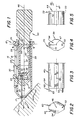
- Figure 1 is a sectioned elevational view of a phlebotomy device constructed with a handle in accordance with the present invention;
- Figure 2 is a sectioned view of the handle taken generally along the line 2-2 of Figure 1;
- Figure 3 is a fragmentary side elevational view of the handle shown in Figure 2;
- Figure 4 is an end elevational view of the phlebotomy device taken generally along the line 4-4 of Figure 1;
- Figure 5 is a fragmentary side elevational view of the device shown in Figure 4;
- Figure 6 is a fragmentary side elevational view showing the movement of the handle to latch it in place; and
- Figure 7 is a fragmentary elevational view of the use of the handle of the invention with a piston in a drug-injecting syringe.
- The invention is described particularly in reference to the preferred embodiments featuring certain phlebotomy devices and syringes for blood collection and drug injection respectively. In addition, it is useful regardless of the design of the phlebotomy device or syringe, and regardless of whether the syringe is used with drugs or some other material.
- Turning first to Figure 1, any
phlebotomy device 10 can be provided with ahandle 40 of the invention. Preferably,device 10 comprises aneedle mounting member 12 in which a needle 14 is permanently embedded,member 12 in turn being slidable mounted in a safety shield orhousing 16. Such ashield 16 cooperates withmember 12 as described in US Patent Application Serial No. 481838. However, such ashield 16 is optional and can be omitted. If included,shield 16 has a needle aperture 17 andrecesses 18 and 20 which co-act with one ormore detents 22 onmember 12 to releasably hold the needle and mountingmember 12 in one of two positions. In addition,locking tab 24 is formed atend 26 ofshield 16, to cooperate with alatch 28 onmember 12 to permanently hold the needle withdrawn after all blood is collected and the mounting member is withdrawn (in the direction indicated by arrow 30). - With or without the
shield 16, needle 14 includes anend 32 which projects intomember 12, with acollapsible sleeve 34 covering it. This end is designed to penetrate aseptum 36 at oneend 38 of a blood-collectingcontainer 39, as is conventional. The container includes at least one liquid-confining compartment 42 and alongitudinal axis 47. - In accordance with the invention,
opposite end 44 ofcontainer 39 has ahandle 40 removably attached thereto.Handle 40 has an axis 46 (Figure 3) which ensures that when the handle is latched, as shown in Figure 1,axis 46 coincides withaxis 47 ofcontainer 39. - To provide for a positive latching of the handle, in a manner which geometrically distinguishes the latched condition from the unlatched condition, the following features are included:
End 44 ofcontainer 39 has anaperture 50 which extends parallel toaxis 47, as shown in Figure 4. A corresponding,mating pivot pin 52 projects fromend 54 of handle 40 (Figures 2 and 3) and is also parallel toaxis 46, in a position so as to line up withaperture 50 whenaxis 46 ofhandle 40 is aligned withaxis 47. However, to ensure that the unlatched configuration ofhandle 40 is distinguishable from the latched one,pin 52 andaperture 50 are disposed to be offset fromaxes - The positive latching of the
handle 40 tocontainer 39 is further achieved by a hook orbayonet member 60 mounted onhandle 40, as shown in Figure 3, thehandle 40 sliding into amating groove 70 formed inend 44 of container 39 (Figure 4).Member 60 has ahook end 62 which projects into the handle towardaxis 46, and cooperates with arecess 72 which also projects inwardly ofcontainer 39 towards axis 47 (Figure 5). - The assembly of
handle 40 into its latched position is shown in Figure 6.End 54 is abutted againstend 44 ofcontainer 39 so thatpin 52 is inserted intoaperture 50, and the handle is rotated, in the direction ofarrow 80, to bringhook member 60 intogroove 70 oncontainer 39. Whenhook end 62 seats intorecess 72, as shown byarrow 82, the latching is complete and any axially directed force F (indicated by arrow 84) is ineffective in separatinghandle 40 fromcontainer 39. - After blood collection is complete,
handle 40 anddevice 39 are pulled out ofhousing 16, and thehandle 40 is removed. Thereafter,device 39 can be further processed to achieve serum separation using conventional techniques. - Handle 40 has several advantages stemming from its construction. When it is fully latched to
container 39, the latching is a positive engagement which cannot slip, as some frictional engagements are capable of doing. Furthermore, the latched and unlatched configurations are, by reason of their different axial alignments, clearly distinguishable one from the other (compare Figures 1 and 6), so that the user is able to identify which condition is present simply from the geometry. Still further, the use of the removable handle permits device 39 (Figure 1) to be greatly reduced in size to the point at which it fits totally insidehousing 16, thus becoming non-manipulable without thehandle 40. For example, the total length ofdevice 39 can be reduced to only 2.5cm (1in). This is particularly useful as blood draws are reduced in volume to supply analyzers which need much less sample. - It will be readily appreciated that
pin 52 andaperture 50 can be reversed (not shown) so that the pin is oncontainer 39. Likewise,member 60 andgroove 70 can be reversed, so thatmember 60 is oncontainer 39. - It will also be appreciated that the removable handle will readily attach to a piston of a drug-injecting syringe, as shown in Figure 7. Parts similar to those previously described bear the same reference numeral, to which the distinguishing suffix A has been appended.
- Thus, handle 40A is readily attachable and removable from a
piston 100 having an outside diameter d₁, where the outside diameter d₂ ofhandle 40A preferably is slightly less than d₁.Piston 100 slides intoend 110 withincompartment 42A of drug-delivery syringe 12A which mounts aneedle 14A atopposite end 112. The syringe construction is conventional, so that no further discussion is required. - The engagement of handle and piston is substantially the same as for the previous embodiment -
pivot pin 52A is inserted intoaperture 50A, and the handle rotated untilmember 60A latches intogroove 70A in the surface ofpiston 100 andaxis 46A ofhandle 40A coincides withaxis 47A ofpiston 100. Thereafter,piston 100 can be pushed into container 39A to push the liquid contents out ofneedle 14A. The advantages ofhandle 40 enumerated above for the phlebotomy device accrue as well forhandle 40A.
Claims (5)
- A blood collecting or drug-injecting device comprising:-
a reservoir (39; 39A) in which blood is collected or in which a drug is retained prior to injection respectively, the reservoir (39; 39A) having a longitudinal axis (47; 47A);
a needle (14; 14A) connected to the reservoir (39; 39A) and through which transmission of blood out of or a drug into a patient is effected; and
a handle (40; 40A) connectable to the reservoir (39; 39A) to aid insertion of the needle (14; 14A) into the patient and its subsequent removal after blood has been collected or a drug delivered, the handle (40; 40A) having a longitudinal axis (46; 46A);
characterized in that either one of the handle (40; 40A) or the reservoir (39; 39A) has a pivot pin (52; 52A) formed thereon which frictionally mates with an aperture (50; 50A) formed in the other of the handle (40; 40A) or reservoir (39; 39A), the pivot pin (52; 52A) and the aperture (50; 50A) both being offset from and extending generally parallel to the respective longitudinal axes (46, 47; 46A, 47A) so as to asymmetrically join the handle (40; 40A) to the reservoir (39; 39A) in a rotational orientation;
and in that latching means (60, 62, 70, 72; 60A, 70A) are provided for latching the handle (40; 40A) and the reservoir (39; 39A) together to prevent the pin (52; 52A) and the aperture (50; 50A) from being axially separated by opposing forces applied along the longitudinal axes (46, 47; 46A, 47A). - A device according to claim 1, wherein the latching means (60, 62, 70, 72; 60A, 70A) comprises a bayonet member (60, 62; 60A) formed on the handle (40; 40A) which engages with a latch groove (70, 72; 70A) formed on the reservoir (39; 39A), the bayonet member (60, 62; 60A) including a hook end (62), and the latching groove (70, 72; 70A) including a recess (72), the handle (40; 40A) being rotated relative to the reservoir (39; 39A) to cause hook end (62) to seat in recess (72) to complete the latching.
- A device according to claim 1, wherein the latching means (60, 62, 70, 72; 60A, 70A) comprises a bayonet member (60, 62; 60A) formed on the reservoir (39; 39A) which engages with a latch groove (70, 72; 70A) formed on the handle (40; 40A), the bayonet member (60, 62; 60A) including a hook end (62), and the latching groove (70, 72; 70A) including a recess (72), the handle (40; 40A) being rotated relative to the reservoir (39; 39A) to cause hook end (62) to seat in recess (72) to complete the latching.
- A device according to any one of the preceding claims, wherein the device is a phlebotomy tube.
- A device according to any one of the preceding claims, wherein the device is a drug-injecting syringe.
Applications Claiming Priority (2)
| Application Number | Priority Date | Filing Date | Title |
|---|---|---|---|
| US481839 | 1990-02-20 | ||
| US07/481,839 US5050617A (en) | 1990-02-20 | 1990-02-20 | Removable handle and means for attachment to a syringe or phlebotomy device |
Publications (1)
| Publication Number | Publication Date |
|---|---|
| EP0443667A1 true EP0443667A1 (en) | 1991-08-28 |
Family
ID=23913593
Family Applications (1)
| Application Number | Title | Priority Date | Filing Date |
|---|---|---|---|
| EP91200299A Withdrawn EP0443667A1 (en) | 1990-02-20 | 1991-02-13 | Removable handle and means for attachment to a syringe or phlebotomy device |
Country Status (6)
| Country | Link |
|---|---|
| US (1) | US5050617A (en) |
| EP (1) | EP0443667A1 (en) |
| JP (1) | JPH05134A (en) |
| KR (1) | KR910021250A (en) |
| CA (1) | CA2034771A1 (en) |
| IE (1) | IE910557A1 (en) |
Cited By (2)
| Publication number | Priority date | Publication date | Assignee | Title |
|---|---|---|---|---|
| EP0539801A2 (en) * | 1991-10-28 | 1993-05-05 | Pall Corporation | Phlebotomist protector apparatus |
| EP0828529A1 (en) * | 1995-05-17 | 1998-03-18 | Creative Biotech, Inc. | Stick-free syringe and associated methods |
Families Citing this family (16)
| Publication number | Priority date | Publication date | Assignee | Title |
|---|---|---|---|---|
| US5514097A (en) * | 1994-02-14 | 1996-05-07 | Genentech, Inc. | Self administered injection pen apparatus and method |
| US5709663A (en) * | 1996-02-06 | 1998-01-20 | Younkes; William E. | Syringe infusion device |
| US7004928B2 (en) | 2002-02-08 | 2006-02-28 | Rosedale Medical, Inc. | Autonomous, ambulatory analyte monitor or drug delivery device |
| US7052652B2 (en) | 2003-03-24 | 2006-05-30 | Rosedale Medical, Inc. | Analyte concentration detection devices and methods |
| US20050070819A1 (en) * | 2003-03-31 | 2005-03-31 | Rosedale Medical, Inc. | Body fluid sampling constructions and techniques |
| US20060281187A1 (en) | 2005-06-13 | 2006-12-14 | Rosedale Medical, Inc. | Analyte detection devices and methods with hematocrit/volume correction and feedback control |
| EP1928304B1 (en) | 2005-09-30 | 2012-10-24 | Intuity Medical, Inc. | Catalysts for body fluid sample extraction |
| US8801631B2 (en) | 2005-09-30 | 2014-08-12 | Intuity Medical, Inc. | Devices and methods for facilitating fluid transport |
| EP2293719B1 (en) | 2008-05-30 | 2015-09-09 | Intuity Medical, Inc. | Body fluid sampling device -- sampling site interface |
| EP3900615A3 (en) | 2008-06-06 | 2022-03-30 | Intuity Medical, Inc. | Detection meter and mode of operation |
| EP3984454A1 (en) | 2008-06-06 | 2022-04-20 | Intuity Medical, Inc. | Medical diagnostic devices and methods |
| EP3106871B1 (en) | 2009-11-30 | 2021-10-27 | Intuity Medical, Inc. | A method of verifying the accuracy of the operation of an analyte monitoring device |
| EP2584964B1 (en) | 2010-06-25 | 2021-08-04 | Intuity Medical, Inc. | Analyte monitoring devices |
| EP4339613A3 (en) | 2011-08-03 | 2024-05-22 | Intuity Medical, Inc. | Body fluid sampling arrangement |
| WO2014205412A1 (en) | 2013-06-21 | 2014-12-24 | Intuity Medical, Inc. | Analyte monitoring system with audible feedback |
| US10865734B2 (en) | 2017-12-06 | 2020-12-15 | Ai Alpine Us Bidco Inc | Piston assembly with offset tight land profile |
Citations (4)
| Publication number | Priority date | Publication date | Assignee | Title |
|---|---|---|---|---|
| US3045674A (en) * | 1958-11-24 | 1962-07-24 | Graham Chemical Corp | Hypodermic syringe piston |
| US3388941A (en) * | 1966-09-16 | 1968-06-18 | Joel A. Marcus | Syringe hand gripping device |
| DE1491661A1 (en) * | 1965-11-24 | 1969-08-28 | Black Robert Beauregard | Injection syringe |
| US4677980A (en) * | 1984-06-06 | 1987-07-07 | Medrad, Inc. | Angiographic injector and angiographic syringe for use therewith |
Family Cites Families (4)
| Publication number | Priority date | Publication date | Assignee | Title |
|---|---|---|---|---|
| DE218668C (en) * | ||||
| US4014322A (en) * | 1975-10-23 | 1977-03-29 | The Kendall Company | Specimen collecting device and method |
| US4507117A (en) * | 1983-07-11 | 1985-03-26 | Vining Herbert C | Syringe apparatus with retractable needle |
| US4892107A (en) * | 1988-01-05 | 1990-01-09 | Habley Medical Technology Corp. | Single use, safety blood collection device |
-
1990
- 1990-02-20 US US07/481,839 patent/US5050617A/en not_active Expired - Fee Related
-
1991
- 1991-01-23 CA CA002034771A patent/CA2034771A1/en not_active Abandoned
- 1991-02-13 EP EP91200299A patent/EP0443667A1/en not_active Withdrawn
- 1991-02-18 KR KR1019910002551A patent/KR910021250A/en not_active Application Discontinuation
- 1991-02-19 IE IE055791A patent/IE910557A1/en unknown
- 1991-02-19 JP JP3024808A patent/JPH05134A/en active Pending
Patent Citations (4)
| Publication number | Priority date | Publication date | Assignee | Title |
|---|---|---|---|---|
| US3045674A (en) * | 1958-11-24 | 1962-07-24 | Graham Chemical Corp | Hypodermic syringe piston |
| DE1491661A1 (en) * | 1965-11-24 | 1969-08-28 | Black Robert Beauregard | Injection syringe |
| US3388941A (en) * | 1966-09-16 | 1968-06-18 | Joel A. Marcus | Syringe hand gripping device |
| US4677980A (en) * | 1984-06-06 | 1987-07-07 | Medrad, Inc. | Angiographic injector and angiographic syringe for use therewith |
Cited By (4)
| Publication number | Priority date | Publication date | Assignee | Title |
|---|---|---|---|---|
| EP0539801A2 (en) * | 1991-10-28 | 1993-05-05 | Pall Corporation | Phlebotomist protector apparatus |
| EP0539801A3 (en) * | 1991-10-28 | 1993-12-15 | Miles Inc | Phlebotomist protector apparatus |
| EP0828529A1 (en) * | 1995-05-17 | 1998-03-18 | Creative Biotech, Inc. | Stick-free syringe and associated methods |
| EP0828529A4 (en) * | 1995-05-17 | 1999-11-17 | Creative Biotech Inc | Stick-free syringe and associated methods |
Also Published As
| Publication number | Publication date |
|---|---|
| KR910021250A (en) | 1991-12-20 |
| US5050617A (en) | 1991-09-24 |
| IE910557A1 (en) | 1991-09-25 |
| CA2034771A1 (en) | 1991-08-21 |
| JPH05134A (en) | 1993-01-08 |
Similar Documents
| Publication | Publication Date | Title |
|---|---|---|
| EP0443667A1 (en) | Removable handle and means for attachment to a syringe or phlebotomy device | |
| EP0753317B1 (en) | Needle point guard assembly | |
| EP0322129A2 (en) | Catheter insert device | |
| AU721815B2 (en) | Needle holder for fluid collection and/or injection system | |
| US5259392A (en) | Blood collection device | |
| AU2007249578B2 (en) | Blood collection device with needle container means | |
| US5637101A (en) | Quick release needle coupling system | |
| EP1816947B1 (en) | Blood collection assembly | |
| EP1568321B1 (en) | Safety blood collection holder | |
| US20060276772A1 (en) | Bayonet release of safety shield for needle tip | |
| US4871355A (en) | Injury resistant needle and blood collection tube holder | |
| US7413560B2 (en) | Safety arteriovenous fistula needle | |
| EP0286087A2 (en) | Medical device | |
| EP0499077A1 (en) | I.V. Infusion or blood collection assembly with automatic safety feature | |
| EP2229888A1 (en) | Retractable Needle-Safety Blood Sampling Device | |
| EP0957957B1 (en) | Shielding means | |
| US20030073958A1 (en) | Disposable aspirating safety syringe | |
| JP2003325482A (en) | Safety blood collection needle assembly | |
| EP0566671A1 (en) | Needle protection device. | |
| EP1472979B1 (en) | Holder assembly for medical needle | |
| CA2042695C (en) | Universal blood draw safety holder | |
| US6616637B2 (en) | Fluid collection safety syringe | |
| EP0570539A1 (en) | Safety device for medical syringe | |
| WO2020157637A1 (en) | Syringe | |
| EP1829480A2 (en) | Cannula retractable medical collection device |
Legal Events
| Date | Code | Title | Description |
|---|---|---|---|
| PUAI | Public reference made under article 153(3) epc to a published international application that has entered the european phase |
Free format text: ORIGINAL CODE: 0009012 |
|
| AK | Designated contracting states |
Kind code of ref document: A1 Designated state(s): BE CH DE FR GB IT LI LU NL |
|
| 17P | Request for examination filed |
Effective date: 19920206 |
|
| 17Q | First examination report despatched |
Effective date: 19930609 |
|
| STAA | Information on the status of an ep patent application or granted ep patent |
Free format text: STATUS: THE APPLICATION IS DEEMED TO BE WITHDRAWN |
|
| 18D | Application deemed to be withdrawn |
Effective date: 19931020 |