EP0442641B1 - Disk file with isolation mount - Google Patents
Disk file with isolation mount Download PDFInfo
- Publication number
- EP0442641B1 EP0442641B1 EP91300881A EP91300881A EP0442641B1 EP 0442641 B1 EP0442641 B1 EP 0442641B1 EP 91300881 A EP91300881 A EP 91300881A EP 91300881 A EP91300881 A EP 91300881A EP 0442641 B1 EP0442641 B1 EP 0442641B1
- Authority
- EP
- European Patent Office
- Prior art keywords
- flexure
- frame
- magnetic disk
- disk file
- head
- Prior art date
- Legal status (The legal status is an assumption and is not a legal conclusion. Google has not performed a legal analysis and makes no representation as to the accuracy of the status listed.)
- Expired - Lifetime
Links
Images


Classifications
-
- G—PHYSICS
- G11—INFORMATION STORAGE
- G11B—INFORMATION STORAGE BASED ON RELATIVE MOVEMENT BETWEEN RECORD CARRIER AND TRANSDUCER
- G11B33/00—Constructional parts, details or accessories not provided for in the other groups of this subclass
- G11B33/12—Disposition of constructional parts in the apparatus, e.g. of power supply, of modules
- G11B33/121—Disposition of constructional parts in the apparatus, e.g. of power supply, of modules the apparatus comprising a single recording/reproducing device
-
- G—PHYSICS
- G11—INFORMATION STORAGE
- G11B—INFORMATION STORAGE BASED ON RELATIVE MOVEMENT BETWEEN RECORD CARRIER AND TRANSDUCER
- G11B33/00—Constructional parts, details or accessories not provided for in the other groups of this subclass
- G11B33/02—Cabinets; Cases; Stands; Disposition of apparatus therein or thereon
- G11B33/08—Insulation or absorption of undesired vibrations or sounds
Definitions
- This invention relates to disk files and more particularly to an isolation mount for a head-disk enclosure within a disk file.
- shock mounting reduces the possibility of damage from a sudden impact, such as dropping the device onto a hard surface.
- Some devices require isolation mounts, which not only protect against shocks and other high frequency vibrations, but also against lower frequency vibrations as well. These mounts must additionally be able to cope with internally generated vibrations, for example those due to the access motion of a disk file actuator.
- a mount frequency which is the natural frequency of oscillation of the mounted device due to the elastic restoring force of the mounts.
- the gain For a device driven by input oscillations of a given frequency and amplitude, the ratio of the amplitude of the output response oscillations to that of the input oscillations is referred to as the gain.
- the general variation of gain with frequency (termed the transfer function) is well known for such systems.
- the gain is approximately unity - i.e. the system behaves as if the mounting were simply a rigid connection.
- the driving input frequency becomes comparable with the mount frequency, resonance occurs and the gain becomes large.
- the gain falls beneath unity, and thereafter the gain continues to decrease with increasing frequency.
- mount frequency can be used to control vibration at different frequencies.
- mounts include some form of damping to further reduce motion, and this can also affect the height, width, and exact position of the mount frequency resonance.
- shock mounts of the prior art have not achieved compactness and consistent, low mount frequencies that are relatively insensitive to temperature variation.
- the invention provides a magnetic disk file including: a frame; a head-disk enclosure containing a disk stack assembly and an actuator; and a plurality of isolation mounts supporting said head-disk enclosure within said frame; said magnetic disk file being characterised in that each of said isolation mounts includes a constrained layer flexure, said constrained layer flexure being substantially planar in form and including a layer of a damping agent sandwiched between two constraining layers of substantially greater rigidity than said damping agent.
- a constrained layer flexure offers a compact isolation mount with a very low mount frequency for the head-disk enclosure within a disk file.
- the low mount frequency offers good protection against high frequency vibrations, both those generated internally, for example by the motion of the actuator, and also those generated externally. Furthermore, the properties of this mount are relatively insensitive to temperature variations.
- the constrained layer flexure is not pliant in a direction parallel to the access direction of the actuator.
- the mount frequency in the access direction of the head-disk enclosure is sufficiently low that vibrations at frequencies outside the bandwidth of the closed-loop servo system are attenuated by the isolation mounts.
- the mount frequency can be much higher in the plane orthogonal to the access direction, reducing the need for sway space in this plane.
- constrained layer flexures are particularly useful in a disk file with a linear actuator, there is no reason why they should not be employed in a disk file with a rotary actuator, in which case other orientations of mounts, and conceivably more than one type of mount, may be desirable.
- the flexure has an elongated form and may be attached to the frame by a rivet at each end.
- the preferred construction of the flexure comprises a layer of viscoelastic rubber sandwiched between two layers of steel, although other materials could be used.
- the flexure has an H-shaped frame, with an aperture located within the central cross-piece. Said H-shaped frame has additional cross-pieces top and bottom, each cross-piece having an inwardly turned tab which accommodates the rivets that attach the flexure to the frame. This effectively extends the length of the flexure, permitting a lower mount frequency to be obtained.
- flexures with different shapes, such as a disk-shaped diaphragm could be also used.
- the isolation mount further includes a resilient grommet located within the aperture in the flexure central cross-piece.
- the head-disk enclosure is supported by a bolt that passes through the grommet, and the grommet includes a flange that lies between the flexure and the frame, so as to prevent the flexure and the frame coming into contact in the case of excessive displacement of the head-disk enclosure.
- the grommet in each isolation mount would be made of rubber.
- the grommets make the mount more resistant to shocks, especially in a plane orthogonal to the access direction, and also act as a snubber to prevent buckling in the case of excessive motion in the access direction.
- Figure 1 shows a head-disk enclosure 1 from a computer disk drive.
- the head-disk enclosure is supported inside frame 2 by four isolation mounts 3.
- the contents of the head-disk enclosure are shown in simplified form in Figure 2, including rotatable data storage disks 13, read/write heads 14 for transferring data to and from the disks, and an actuator mechanism 15 for moving the heads across the disks.
- a servo control system is used to position the heads accurately over the disks.
- the disks are rotated about spindle 12 by an in-hub motor (not shown).
- the actuator of Figures 1 and 2 is a linear actuator; i.e. the read/write heads are moved in and out linearly across a disk radius.
- the direction of this motion referred to as the access direction, is indicated by arrow A.
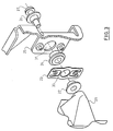
- FIGS 3 and 4 show the isolation mounts of Figure 1 in more detail.
- Bracket 25, which is part of frame 2 has three holes in it. The top and bottom holes are used for rivets 28 for attaching a constrained layer flexure 23 to bracket 25.
- the constrained layer flexure is essentially parallel to the bracket, and includes a hole 30 aligned with the central hole 31 in bracket 25.
- a rubber grommet or bush 24 is located in hole 30.
- the bush is a hollow cylindrical shape, with two flanges 41,43 and a groove 42 between them. The inner rim of hole 30 is received in groove 42.
- Two metallic bushes 22, 26 are inserted into the rubber grommet, one from each end.
- Each of the metal bushes has a flange which stops complete insertion of the bushes into the grommet: as a result there is a slight gap inside the grommet between the ends of the two bushes.
- the metal bushes are present primarily for assembly reasons and to strengthen the mounting.
- a bolt 27 passes through the rubber and metallic bushes and into bore 21 in the head-disk assembly enclosure casting.
- the access direction is orthogonal to the plane of the flexures - i.e. parallel to the direction in which the flexures are most pliant.
- curve A in Figure 5 One of the original design requirements for the mount is sketched in curve A in Figure 5. This shows the allowable gain at the mount frequency if external vibrations are not to induce head positioning errors whilst track following.
- the closed-loop servo system used for controlling the actuator includes an integrator with a corner frequency of about 50 Hz. This effectively limits the overall bandwidth of the closed-loop servo system, explaining why the vibration tolerance increases rapidly below this frequency. Initially, relatively stiff rubber grommets were used for mounting the head-disk enclosure, providing a mount frequency of over 100 Hz.
- the constrained layer flexures 23 comprise two layers of steel with an intervening layer of viscoelastic rubber.
- the central layer of rubber acts as a damping agent to remove the energy of any vibrations.
- Each flexure is riveted top and bottom to the bracket 25 on the support frame.
- the flexures are elongated in shape. In fact, by folding each flexure back on itself the effective elongation has been artificially increased, lowering the mount frequency still further.
- the mount frequency is much higher however orthogonal to the access direction and for rotational vibrations, which reduces the necessary amount of sway space and avoids problems with the disk drive motor.
- the rubber grommets 24 are useful primarily for fragility performance, adding some flexibility for motion perpendicular to the access direction, and so function essentially as shock mounts. They both increase the buckling load of the flexure, and ensure that this buckling load is not reached.
- the grommets are also of great use for preventing the flexure from bending too greatly and coming into hard contact with support bracket. Instead, flange 43 acts as a snubber, so that if the flexure gives too far to the right in Figure 4, the flange is sandwiched between the flexure and the bracket, increasing stiffness, but without the fragility problems that would arise should the flexure come into direct contact with the bracket.
Landscapes
- Supporting Of Heads In Record-Carrier Devices (AREA)
- Moving Of Heads (AREA)
- Vibration Prevention Devices (AREA)
Description
- This invention relates to disk files and more particularly to an isolation mount for a head-disk enclosure within a disk file.
- It is common for sensitive electrical apparatus, such as computer disk drives, to be shock mounted within a frame. The shock mounting reduces the possibility of damage from a sudden impact, such as dropping the device onto a hard surface. Some devices require isolation mounts, which not only protect against shocks and other high frequency vibrations, but also against lower frequency vibrations as well. These mounts must additionally be able to cope with internally generated vibrations, for example those due to the access motion of a disk file actuator.
- Associated with a shock or isolation mount is a mount frequency, which is the natural frequency of oscillation of the mounted device due to the elastic restoring force of the mounts. For a device driven by input oscillations of a given frequency and amplitude, the ratio of the amplitude of the output response oscillations to that of the input oscillations is referred to as the gain. The general variation of gain with frequency (termed the transfer function) is well known for such systems. For input oscillations at much less than the natural (in our case mount) frequency, the gain is approximately unity - i.e. the system behaves as if the mounting were simply a rigid connection. Then, as the driving input frequency becomes comparable with the mount frequency, resonance occurs and the gain becomes large. Finally, above the mount frequency resonance, the gain falls beneath unity, and thereafter the gain continues to decrease with increasing frequency.
- In the design of a shock or isolation mount, adjustment of the mount frequency can be used to control vibration at different frequencies. Typically such mounts include some form of damping to further reduce motion, and this can also affect the height, width, and exact position of the mount frequency resonance.
- One common type of prior art shock mount is described in PCT application WO 88/09551. In this design, a rubber grommet is placed around a cylindrical projection of the head-disk enclosure (or alternatively around a bolt that is screwed partway into the head-disk enclosure). The grommet is then held within the support frame, to provide a shock mount for the head-disk enclosure. Typically there are three or four such shock mounts connecting the head-disk enclosure to the support frame. A slight variation of this method is disclosed in US 4812932, which describes a grommet with a spring constant that is arranged to vary significantly with displacement. US 4683520 discloses a shock mount which again uses a grommet, but instead of having the grommet held directly by the frame, attaches it to a cantilevered extension of the frame.
- A somewhat different mounting system for unspecified electrical equipment is disclosed in Canadian patent 788873. This uses a panel of laminar material including a damping layer as a support structure for apparatus. Resilient grommets are used to attach the panel to a frame, and apparatus to the panel. The use of the panel enhances the isolation properties of the mount.
- The shock mounts of the prior art have not achieved compactness and consistent, low mount frequencies that are relatively insensitive to temperature variation.
- Accordingly, the invention provides a magnetic disk file including: a frame; a head-disk enclosure containing a disk stack assembly and an actuator; and a plurality of isolation mounts supporting said head-disk enclosure within said frame; said magnetic disk file being characterised in that each of said isolation mounts includes a constrained layer flexure, said constrained layer flexure being substantially planar in form and including a layer of a damping agent sandwiched between two constraining layers of substantially greater rigidity than said damping agent.
- The use of a constrained layer flexure offers a compact isolation mount with a very low mount frequency for the head-disk enclosure within a disk file. The low mount frequency offers good protection against high frequency vibrations, both those generated internally, for example by the motion of the actuator, and also those generated externally. Furthermore, the properties of this mount are relatively insensitive to temperature variations.
- In the case where the actuator is a linear actuator, it is preferable that the constrained layer flexure is not pliant in a direction parallel to the access direction of the actuator. For an actuator controlled by a closed-loop servo system, it is also preferable that the mount frequency in the access direction of the head-disk enclosure is sufficiently low that vibrations at frequencies outside the bandwidth of the closed-loop servo system are attenuated by the isolation mounts. The mount frequency can be much higher in the plane orthogonal to the access direction, reducing the need for sway space in this plane. Although constrained layer flexures are particularly useful in a disk file with a linear actuator, there is no reason why they should not be employed in a disk file with a rotary actuator, in which case other orientations of mounts, and conceivably more than one type of mount, may be desirable.
- Preferably, the flexure has an elongated form and may be attached to the frame by a rivet at each end. The preferred construction of the flexure comprises a layer of viscoelastic rubber sandwiched between two layers of steel, although other materials could be used. Preferably the flexure has an H-shaped frame, with an aperture located within the central cross-piece. Said H-shaped frame has additional cross-pieces top and bottom, each cross-piece having an inwardly turned tab which accommodates the rivets that attach the flexure to the frame. This effectively extends the length of the flexure, permitting a lower mount frequency to be obtained. However, flexures with different shapes, such as a disk-shaped diaphragm, could be also used.
- It is also preferred that the isolation mount further includes a resilient grommet located within the aperture in the flexure central cross-piece. The head-disk enclosure is supported by a bolt that passes through the grommet, and the grommet includes a flange that lies between the flexure and the frame, so as to prevent the flexure and the frame coming into contact in the case of excessive displacement of the head-disk enclosure.
- Typically, the grommet in each isolation mount would be made of rubber. The grommets make the mount more resistant to shocks, especially in a plane orthogonal to the access direction, and also act as a snubber to prevent buckling in the case of excessive motion in the access direction.
-
- Figure 1 shows an exploded view of a disk file according to the invention comprising a head-disk enclosure, a support frame, and isolation mounts;
- Figure 2 shows an exploded view of the head-disk enclosure of Figure 1;
- Figure 3 shows an exploded detailed view of one of the isolation mounts of Figure 1 in relation to adjacent portions of the head-disk enclosure and support frame;
- Figure 4 shows a detailed cross-section through the isolation mount of Figure 3;
- Figure 5 compares the mount design specifications for maximum gain versus frequency with the gain of an isolation mount embodying the invention, and that of a prior art rubber grommet isolation mount.
- Figure 1 shows a head-
disk enclosure 1 from a computer disk drive. The head-disk enclosure is supported insideframe 2 by fourisolation mounts 3. The contents of the head-disk enclosure are shown in simplified form in Figure 2, including rotatabledata storage disks 13, read/writeheads 14 for transferring data to and from the disks, and anactuator mechanism 15 for moving the heads across the disks. A servo control system is used to position the heads accurately over the disks. The disks are rotated aboutspindle 12 by an in-hub motor (not shown). The actuator of Figures 1 and 2 is a linear actuator; i.e. the read/write heads are moved in and out linearly across a disk radius. The direction of this motion, referred to as the access direction, is indicated by arrow A. - Figures 3 and 4 show the isolation mounts of Figure 1 in more detail.
Bracket 25, which is part offrame 2, has three holes in it. The top and bottom holes are used forrivets 28 for attaching a constrainedlayer flexure 23 tobracket 25. The constrained layer flexure is essentially parallel to the bracket, and includes ahole 30 aligned with thecentral hole 31 inbracket 25. A rubber grommet orbush 24 is located inhole 30. The bush is a hollow cylindrical shape, with twoflanges groove 42 between them. The inner rim ofhole 30 is received ingroove 42. Twometallic bushes bolt 27 passes through the rubber and metallic bushes and intobore 21 in the head-disk assembly enclosure casting. The access direction is orthogonal to the plane of the flexures - i.e. parallel to the direction in which the flexures are most pliant. - One of the original design requirements for the mount is sketched in curve A in Figure 5. This shows the allowable gain at the mount frequency if external vibrations are not to induce head positioning errors whilst track following. The closed-loop servo system used for controlling the actuator includes an integrator with a corner frequency of about 50 Hz. This effectively limits the overall bandwidth of the closed-loop servo system, explaining why the vibration tolerance increases rapidly below this frequency. Initially, relatively stiff rubber grommets were used for mounting the head-disk enclosure, providing a mount frequency of over 100 Hz. However, the track following performance with these mounts was found to be unsatisfactory, since external vibrations with frequencies outside the servo bandwidth but below the mount frequency (ie: typically in the range 50-100Hz) were not attenuated by the mounts, yet could not be followed using the servo. Furthermore, a stiff mounting provided inadequate damping at certain temperatures, and also, at high temperatures, the torsional resonance was too close to the disk rotation speed, causing problems for the spindle motor servo control system.
- A grommet mounting with a mount frequency less than the servo bandwidth was then tried so as to reduce this susceptibility to external vibrations by moving under the more tolerant region of curve A. Rubber grommet mountings with a mount frequency of about 40 Hz and a transfer function as shown by curve B were obtained. Although these could satisfy the external vibration requirement of curve A, severe problems remained. It was only possible to achieve the necessary damping by using mounts whose stiffness, and hence mount frequency, varied significantly over the disk drive operating temperature range. Furthermore, the grommets had a low side stiffness (i.e. perpendicular to the access direction) and required more sway space in this plane than was available. Another difficulty was the low rotational frequency of the mount, which was troublesome on account of the low bandwidth of the disk drive motor. Finally, it was found that during a seek operation, the head-disk enclosure casting moved in reaction to the motion of the actuator, which made it difficult to position the heads quickly and precisely.
- Although no rubber grommet mounting was found that could answer all the above problems, they are successfully overcome by the flexure isolation mount of Figures 3 and 4. The transfer function in the access direction for this mount is shown as curve C in Figure 5, and it can be seen that it easily satisfies the external vibration requirements. The low mount frequency of the flexure mount of around 20 Hz also means that the servo is much more capable of compensating for any movement of the head-disk enclosure in reaction to actuator seeks.
- The constrained
layer flexures 23 comprise two layers of steel with an intervening layer of viscoelastic rubber. The central layer of rubber acts as a damping agent to remove the energy of any vibrations. Each flexure is riveted top and bottom to thebracket 25 on the support frame. To obtain the low mount frequency, the flexures are elongated in shape. In fact, by folding each flexure back on itself the effective elongation has been artificially increased, lowering the mount frequency still further. The mount frequency is much higher however orthogonal to the access direction and for rotational vibrations, which reduces the necessary amount of sway space and avoids problems with the disk drive motor. - The rubber grommets 24 are useful primarily for fragility performance, adding some flexibility for motion perpendicular to the access direction, and so function essentially as shock mounts. They both increase the buckling load of the flexure, and ensure that this buckling load is not reached. The grommets are also of great use for preventing the flexure from bending too greatly and coming into hard contact with support bracket. Instead, flange 43 acts as a snubber, so that if the flexure gives too far to the right in Figure 4, the flange is sandwiched between the flexure and the bracket, increasing stiffness, but without the fragility problems that would arise should the flexure come into direct contact with the bracket.
Claims (9)
- A magnetic disk file including:
a frame (2); a head-disk enclosure (1) containing a disk stack assembly (13) and an actuator (15); and a plurality of isolation mounts (3) supporting said head-disk enclosure within said frame;
said magnetic disk file being characterised in that each of said isolation mounts includes a constrained layer flexure (23), said constrained layer flexure being substantially planar in form and including a layer of a damping agent sandwiched between two constraining layers of substantially greater rigidity than said damping agent. - A magnetic disk file as claimed in claim 1, wherein said actuator is a linear actuator and said flexure is most pliant in a direction parallel to the access direction of said linear actuator.
- A magnetic disk file as claimed in claim 2, wherein said actuator is controlled by a closed-loop servo system, and wherein the mount frequency in the access direction of said head-disk enclosure is sufficiently low that vibrations at frequencies outside the bandwidth of said closed-loop servo system are attenuated by said isolation mounts.
- A magnetic disk file as claimed in any preceding claim, wherein said flexure has an elongated form and is attached to said frame by rivets (28) at each end of said elongated form.
- A magnetic disk file as claimed in any preceding claim, wherein each of said constrained layer flexures comprises a layer of viscoelastic rubber sandwiched between two layers of steel.
- A magnetic disk file as claimed in any preceding claim, wherein said isolation mount further includes a resilient grommet (24) located in an aperture (30) in said flexure, said head-disk enclosure being supported by a bolt (27) that passes through said grommet.
- A magnetic disk file as claimed in claim 6, wherein said resilient grommet includes a flange (43) that lies between said flexure and said frame, so as to prevent said frame and said flexure coming into contact in the case of excessive displacement of said head-disk enclosure.
- A magnetic disk file as claimed in claim 7, wherein said flexure has an H-shaped frame, said aperture for the grommet being located within the central cross-piece of said H-shaped frame; said H-shaped frame having additional cross-pieces top and bottom, each cross-piece having an inwardly turned tab for attachment to said frame.
- A magnetic disk file as claimed in any preceding claim, wherein said head-disk enclosure is supported in said frame by four of said isolation mounts.
Applications Claiming Priority (2)
| Application Number | Priority Date | Filing Date | Title |
|---|---|---|---|
| GB9003470A GB2241370A (en) | 1990-02-15 | 1990-02-15 | Disk file with isolation mount |
| GB9003470 | 1990-02-15 |
Publications (3)
| Publication Number | Publication Date |
|---|---|
| EP0442641A2 EP0442641A2 (en) | 1991-08-21 |
| EP0442641A3 EP0442641A3 (en) | 1992-04-29 |
| EP0442641B1 true EP0442641B1 (en) | 1995-01-04 |
Family
ID=10671071
Family Applications (1)
| Application Number | Title | Priority Date | Filing Date |
|---|---|---|---|
| EP91300881A Expired - Lifetime EP0442641B1 (en) | 1990-02-15 | 1991-02-04 | Disk file with isolation mount |
Country Status (6)
| Country | Link |
|---|---|
| US (1) | US5124855A (en) |
| EP (1) | EP0442641B1 (en) |
| JP (1) | JPH0664902B2 (en) |
| KR (1) | KR950002399B1 (en) |
| DE (1) | DE69106403T2 (en) |
| GB (1) | GB2241370A (en) |
Cited By (1)
| Publication number | Priority date | Publication date | Assignee | Title |
|---|---|---|---|---|
| US10019043B2 (en) | 2015-12-14 | 2018-07-10 | Western Digital Technologies, Inc. | Hard disk drive with a vibration isolation frame |
Families Citing this family (46)
| Publication number | Priority date | Publication date | Assignee | Title |
|---|---|---|---|---|
| JP2685988B2 (en) * | 1991-03-15 | 1997-12-08 | 株式会社日立製作所 | Magnetic disk drive |
| US5875067A (en) * | 1991-03-22 | 1999-02-23 | Seagate Technology, Inc. | Acoustic isolator for a disc drive assembly |
| US5379171A (en) * | 1991-09-25 | 1995-01-03 | Integral Peripherals | Microminiature hard disk drive |
| US6310747B1 (en) | 1991-09-25 | 2001-10-30 | Mobile Storage Technology, Inc. | Method for reducing external signal interference with signals in a computer disk storage system |
| US5216582A (en) * | 1992-02-10 | 1993-06-01 | Quantum Corporation | Shock mounted disk drive module having snap-lock cover |
| US5400196A (en) * | 1992-04-30 | 1995-03-21 | International Business Machines Corporation | DASD with spindle imbalance isolation and method for producing same |
| JPH0666111B2 (en) * | 1992-05-12 | 1994-08-24 | インターナショナル・ビジネス・マシーンズ・コーポレイション | Impact resistant portable disk storage |
| DE4317546A1 (en) * | 1992-05-27 | 1994-01-20 | Funai Electric Co | Record player with automatic record changer |
| JPH0745060A (en) * | 1993-07-30 | 1995-02-14 | Citizen Watch Co Ltd | Magnetic disk device |
| MY112103A (en) * | 1993-08-26 | 2001-04-30 | Sony Corp | Recording and / or reproducing apparatus for recording medium and damper mechanism employed in such apparatus. |
| US5587879A (en) * | 1994-01-28 | 1996-12-24 | Sun Microsystems, Inc. | Mounting arrangement for computer hardware components and method |
| JPH07254259A (en) * | 1994-03-15 | 1995-10-03 | Hitachi Ltd | Magnetic disc apparatus |
| DE69603274T2 (en) * | 1995-05-19 | 1999-12-16 | Rubber Tech Inc | DISK DRIVE DEVICE WITH VIBRATION DAMPING PROPERTIES |
| US5696649A (en) * | 1995-05-22 | 1997-12-09 | International Business Machines Corporation | Elastic insert shroud to provide maximum effective shrouding shock mitigation and filtering in high speed disk drives |
| KR970022312A (en) * | 1995-10-11 | 1997-05-28 | 구미하시 요시유키 | How to measure specific gravity of fluid |
| US6510021B1 (en) * | 1996-06-03 | 2003-01-21 | Seagate Technology Llc | Mechanical isolation for a disc drive spindle motor |
| DE69701242T2 (en) * | 1996-06-20 | 2000-09-07 | Mitsumi Electric Co Ltd | Disk unit |
| US5896646A (en) | 1997-05-13 | 1999-04-27 | Seagate Technology, Inc. | Base plate with improved torque retention |
| US6175474B1 (en) | 1997-11-07 | 2001-01-16 | Seagate Technology Llc | Base plate with improved torque retention |
| GB2342759A (en) * | 1998-10-10 | 2000-04-19 | Pti Limited | Data cartridge assembly with vibration damping |
| US6320744B1 (en) | 1999-02-19 | 2001-11-20 | General Dynamics Information Systesm, Inc. | Data storage housing |
| US6487039B1 (en) | 1999-06-24 | 2002-11-26 | Seagate Technology Llc | Disc-drive mounting method and apparatus to reduce noise |
| US6999909B1 (en) | 1999-10-28 | 2006-02-14 | Seagate Technology Llc | Process for designing an optimal vibration isolation mount for a disc drive |
| US6477042B1 (en) * | 1999-11-18 | 2002-11-05 | Siemens Energy & Automation, Inc. | Disk drive mounting system for absorbing shock and vibration in a machining environment |
| US6925246B1 (en) | 2000-07-05 | 2005-08-02 | Steinbeck Cannery, Llc | Television recorder having a removeable hard disk drive |
| WO2002009096A2 (en) * | 2000-07-21 | 2002-01-31 | Digital Voice Systems, Inc. | Isolating and reducing noise generated by mechanical data storage devices |
| CN2542884Y (en) * | 2002-04-17 | 2003-04-02 | 鸿富锦精密工业(深圳)有限公司 | Damping structure |
| US7178794B2 (en) * | 2002-09-10 | 2007-02-20 | Seagate Technology Llc | Fluid isolator assembly and floating elastomeric damping element |
| US6882528B2 (en) * | 2003-05-15 | 2005-04-19 | Aaeon Technology Inc. | Suspension-type shock-avoiding structure for a hard disk |
| US7502204B2 (en) * | 2005-12-16 | 2009-03-10 | Seagate Technology Llc | Structures for attaching a head gimbal assembly and an actuator arm |
| US20080158808A1 (en) * | 2006-12-29 | 2008-07-03 | Toshiba America Information Systems, Inc. | Apparatus to protect shock-sensitive devices and methods of assembly |
| US8164849B1 (en) | 2007-12-10 | 2012-04-24 | Western Digital Technologies, Inc. | Information storage device with a conductive shield having free and forced heat convection configurations |
| US7701705B1 (en) | 2007-12-10 | 2010-04-20 | Western Digital Technologies, Inc. | Information storage device with sheet metal projections and elastomeric inserts |
| US8004791B2 (en) * | 2008-02-22 | 2011-08-23 | Western Digital Technologies, Inc. | Information storage device with a bridge controller and a plurality of electrically coupled conductive shields |
| US8390952B1 (en) | 2008-02-22 | 2013-03-05 | Western Digital Technologies, Inc. | Information storage device having a conductive shield with a peripheral capacitive flange |
| US8300352B1 (en) | 2009-06-18 | 2012-10-30 | Western Digital Technologies, Inc. | Disk drive having mounting inserts with cantilevered beams |
| US8213174B1 (en) | 2010-01-08 | 2012-07-03 | Juniper Networks, Inc. | Vibration-damping mount |
| CN203013259U (en) * | 2010-12-27 | 2013-06-19 | 3M创新有限公司 | Multi-thickness hard disk drive snubber |
| US9462717B1 (en) | 2011-06-08 | 2016-10-04 | Hewlett-Packard Development Company, L.P. | Mounting frame to mount a component |
| CN103562815B (en) * | 2011-06-08 | 2016-08-31 | 惠普发展公司,有限责任合伙企业 | For installing installation frame and the support member of the parts of calculating system |
| US8705201B2 (en) | 2011-12-20 | 2014-04-22 | Western Digital Technologies, Inc. | Information storage device with a damping insert sheet between a housing bay and a disk drive |
| US8462460B1 (en) | 2012-03-29 | 2013-06-11 | Western Digital Technologies, Inc. | Shock mount and retainer for a disk drive enclosure |
| US8547658B1 (en) | 2012-10-18 | 2013-10-01 | Western Digital Technologies, Inc. | Data storage device enclosure enabling use of a common shock mount across different products |
| US9360900B1 (en) | 2013-08-21 | 2016-06-07 | Western Digital Technologies, Inc. | Captivating shock mounts for data storage devices using retention clips |
| TWI533784B (en) * | 2013-10-25 | 2016-05-11 | 緯創資通股份有限公司 | Shock-damping component and shock-damping frame and electronic device using the same |
| US11169572B2 (en) | 2019-08-07 | 2021-11-09 | Hand Held Products, Inc. | Protective housing for a mobile device |
Family Cites Families (10)
| Publication number | Priority date | Publication date | Assignee | Title |
|---|---|---|---|---|
| CA788873A (en) * | 1968-07-02 | P. Thorn Richard | Mounting system | |
| US4553183A (en) * | 1982-06-28 | 1985-11-12 | Atasi Corporation | Memory storage apparatus having improved housing and base plate arrangement |
| FR2565395B1 (en) * | 1984-05-29 | 1989-05-26 | Philips Ind Commerciale | DEVICE FOR FAST MOUNTING OF A PLATE ON A CHASSIS, ESPECIALLY FOR A RECORDER |
| DE3522842A1 (en) * | 1985-06-26 | 1987-01-02 | Thomson Brandt Gmbh | ELASTIC DEVICE FOOT FOR ENTERTAINMENT ELECTRONICS |
| US4831476A (en) * | 1985-07-15 | 1989-05-16 | Allen-Bradley Company | Disc drive isolation system |
| GB8601732D0 (en) * | 1986-01-24 | 1986-02-26 | Linn Prod Ltd | Resilient mountings |
| JP2718665B2 (en) * | 1986-07-09 | 1998-02-25 | 株式会社日立製作所 | File storage |
| US4979062A (en) * | 1987-05-29 | 1990-12-18 | Conner Peripherals, Inc. | Disk drive architecture |
| US4908715A (en) * | 1988-03-29 | 1990-03-13 | Magnetic Peripherals Inc. | Disk drive unit |
| JPH02130783A (en) * | 1988-11-11 | 1990-05-18 | Nippon I B M Kk | Vibration damping structure and magnetic disk device |
-
1990
- 1990-02-15 GB GB9003470A patent/GB2241370A/en not_active Withdrawn
- 1990-05-29 US US07/529,823 patent/US5124855A/en not_active Expired - Fee Related
-
1991
- 1991-01-29 KR KR1019910001430A patent/KR950002399B1/en not_active IP Right Cessation
- 1991-02-04 DE DE69106403T patent/DE69106403T2/en not_active Expired - Fee Related
- 1991-02-04 EP EP91300881A patent/EP0442641B1/en not_active Expired - Lifetime
- 1991-02-12 JP JP3060766A patent/JPH0664902B2/en not_active Expired - Lifetime
Cited By (1)
| Publication number | Priority date | Publication date | Assignee | Title |
|---|---|---|---|---|
| US10019043B2 (en) | 2015-12-14 | 2018-07-10 | Western Digital Technologies, Inc. | Hard disk drive with a vibration isolation frame |
Also Published As
| Publication number | Publication date |
|---|---|
| JPH0664902B2 (en) | 1994-08-22 |
| DE69106403T2 (en) | 1995-07-13 |
| DE69106403D1 (en) | 1995-02-16 |
| EP0442641A2 (en) | 1991-08-21 |
| US5124855A (en) | 1992-06-23 |
| GB2241370A (en) | 1991-08-28 |
| JPH04216389A (en) | 1992-08-06 |
| GB9003470D0 (en) | 1990-04-11 |
| EP0442641A3 (en) | 1992-04-29 |
| KR920000055A (en) | 1992-01-10 |
| KR950002399B1 (en) | 1995-03-17 |
Similar Documents
| Publication | Publication Date | Title |
|---|---|---|
| EP0442641B1 (en) | Disk file with isolation mount | |
| KR100491402B1 (en) | Disk storage system and mounting system for head/disk assembly | |
| EP0060358B1 (en) | Head support arm and head/arm assemblies for disk files | |
| US5936803A (en) | Disk drive having a mass balanced head gimbal assembly | |
| US4812932A (en) | Vibration proof supporting structure for disk-type information memory unit | |
| US4346416A (en) | Rotary actuator assembly for disk drive head positioner | |
| US6215623B1 (en) | Dynamic-absorber for the suppression of suspension vibrations | |
| US4703470A (en) | Dynamic absorber device for use with disk drives | |
| US5796553A (en) | Disk drive head suspension having gaps in the load beam which are at least partially filled with or covered by damping material | |
| EP0372684A2 (en) | Data storage apparatus | |
| JPH02232881A (en) | Magnetic disc memory device | |
| US4843503A (en) | Head arm damping device for disc drive actuators | |
| JPH0632202B2 (en) | Anti-vibration structure of disk device | |
| US6377420B1 (en) | Hub cap actuator damper for disc drives | |
| JPH0982052A (en) | Head actuator mechanism of disc-recording/reproducing apparatus | |
| JP2006190375A (en) | Magnetic disk drive | |
| JP3587574B2 (en) | Magnetic disk drive | |
| US6164614A (en) | Mounting frame using an operating vibration damper at a recessed side surface of a disc drive housing | |
| JPS59210572A (en) | Mechanical damper for disc driver having band drive actuator | |
| US6771469B2 (en) | Disc drive inertial head-slap arrestor | |
| JPH03104079A (en) | Magnetic disk device | |
| EP0246375B1 (en) | Head/arm assembly and rotary access mechanism for a disk file | |
| JPH09134577A (en) | Head-loading mechanism of disk apparatus | |
| JP2956182B2 (en) | Disk file device | |
| JP2641453B2 (en) | Magnetic disk drive |
Legal Events
| Date | Code | Title | Description |
|---|---|---|---|
| PUAI | Public reference made under article 153(3) epc to a published international application that has entered the european phase |
Free format text: ORIGINAL CODE: 0009012 |
|
| AK | Designated contracting states |
Kind code of ref document: A2 Designated state(s): DE FR GB IT |
|
| 17P | Request for examination filed |
Effective date: 19911211 |
|
| PUAL | Search report despatched |
Free format text: ORIGINAL CODE: 0009013 |
|
| AK | Designated contracting states |
Kind code of ref document: A3 Designated state(s): DE FR GB IT |
|
| 17Q | First examination report despatched |
Effective date: 19931112 |
|
| GRAA | (expected) grant |
Free format text: ORIGINAL CODE: 0009210 |
|
| AK | Designated contracting states |
Kind code of ref document: B1 Designated state(s): DE FR GB IT |
|
| PG25 | Lapsed in a contracting state [announced via postgrant information from national office to epo] |
Ref country code: IT Free format text: LAPSE BECAUSE OF FAILURE TO SUBMIT A TRANSLATION OF THE DESCRIPTION OR TO PAY THE FEE WITHIN THE PRESCRIBED TIME-LIMIT;WARNING: LAPSES OF ITALIAN PATENTS WITH EFFECTIVE DATE BEFORE 2007 MAY HAVE OCCURRED AT ANY TIME BEFORE 2007. THE CORRECT EFFECTIVE DATE MAY BE DIFFERENT FROM THE ONE RECORDED. Effective date: 19950104 |
|
| PGFP | Annual fee paid to national office [announced via postgrant information from national office to epo] |
Ref country code: GB Payment date: 19950125 Year of fee payment: 5 |
|
| PGFP | Annual fee paid to national office [announced via postgrant information from national office to epo] |
Ref country code: FR Payment date: 19950128 Year of fee payment: 5 |
|
| REF | Corresponds to: |
Ref document number: 69106403 Country of ref document: DE Date of ref document: 19950216 |
|
| PGFP | Annual fee paid to national office [announced via postgrant information from national office to epo] |
Ref country code: DE Payment date: 19950223 Year of fee payment: 5 |
|
| ET | Fr: translation filed | ||
| PLBE | No opposition filed within time limit |
Free format text: ORIGINAL CODE: 0009261 |
|
| STAA | Information on the status of an ep patent application or granted ep patent |
Free format text: STATUS: NO OPPOSITION FILED WITHIN TIME LIMIT |
|
| 26N | No opposition filed | ||
| PG25 | Lapsed in a contracting state [announced via postgrant information from national office to epo] |
Ref country code: GB Effective date: 19960204 |
|
| GBPC | Gb: european patent ceased through non-payment of renewal fee |
Effective date: 19960204 |
|
| PG25 | Lapsed in a contracting state [announced via postgrant information from national office to epo] |
Ref country code: FR Effective date: 19961031 |
|
| PG25 | Lapsed in a contracting state [announced via postgrant information from national office to epo] |
Ref country code: DE Effective date: 19961101 |
|
| REG | Reference to a national code |
Ref country code: FR Ref legal event code: ST |