EP0440846B1 - Two-compartment syringe and application process - Google Patents
Two-compartment syringe and application process Download PDFInfo
- Publication number
- EP0440846B1 EP0440846B1 EP90102373A EP90102373A EP0440846B1 EP 0440846 B1 EP0440846 B1 EP 0440846B1 EP 90102373 A EP90102373 A EP 90102373A EP 90102373 A EP90102373 A EP 90102373A EP 0440846 B1 EP0440846 B1 EP 0440846B1
- Authority
- EP
- European Patent Office
- Prior art keywords
- syringe
- needle
- plunger
- chamber
- plug
- Prior art date
- Legal status (The legal status is an assumption and is not a legal conclusion. Google has not performed a legal analysis and makes no representation as to the accuracy of the status listed.)
- Expired - Lifetime
Links
- 238000000034 method Methods 0.000 title claims description 11
- 239000002904 solvent Substances 0.000 claims abstract description 22
- 238000013016 damping Methods 0.000 claims abstract description 11
- 238000002347 injection Methods 0.000 claims abstract description 5
- 239000007924 injection Substances 0.000 claims abstract description 5
- 239000011521 glass Substances 0.000 claims description 6
- 239000000126 substance Substances 0.000 claims description 6
- 238000006073 displacement reaction Methods 0.000 claims description 5
- 239000003814 drug Substances 0.000 claims description 4
- 239000011149 active material Substances 0.000 claims 3
- 241000220317 Rosa Species 0.000 claims 1
- 230000002093 peripheral effect Effects 0.000 claims 1
- 239000013543 active substance Substances 0.000 abstract description 7
- 239000004480 active ingredient Substances 0.000 description 13
- 239000011324 bead Substances 0.000 description 4
- 238000004090 dissolution Methods 0.000 description 2
- 229940071643 prefilled syringe Drugs 0.000 description 2
- 239000000243 solution Substances 0.000 description 2
- 239000008186 active pharmaceutical agent Substances 0.000 description 1
- 238000002360 preparation method Methods 0.000 description 1
Images
Classifications
-
- A—HUMAN NECESSITIES
- A61—MEDICAL OR VETERINARY SCIENCE; HYGIENE
- A61M—DEVICES FOR INTRODUCING MEDIA INTO, OR ONTO, THE BODY; DEVICES FOR TRANSDUCING BODY MEDIA OR FOR TAKING MEDIA FROM THE BODY; DEVICES FOR PRODUCING OR ENDING SLEEP OR STUPOR
- A61M5/00—Devices for bringing media into the body in a subcutaneous, intra-vascular or intramuscular way; Accessories therefor, e.g. filling or cleaning devices, arm-rests
- A61M5/178—Syringes
- A61M5/31—Details
- A61M5/315—Pistons; Piston-rods; Guiding, blocking or restricting the movement of the rod or piston; Appliances on the rod for facilitating dosing ; Dosing mechanisms
- A61M5/31596—Pistons; Piston-rods; Guiding, blocking or restricting the movement of the rod or piston; Appliances on the rod for facilitating dosing ; Dosing mechanisms comprising means for injection of two or more media, e.g. by mixing
-
- A—HUMAN NECESSITIES
- A61—MEDICAL OR VETERINARY SCIENCE; HYGIENE
- A61M—DEVICES FOR INTRODUCING MEDIA INTO, OR ONTO, THE BODY; DEVICES FOR TRANSDUCING BODY MEDIA OR FOR TAKING MEDIA FROM THE BODY; DEVICES FOR PRODUCING OR ENDING SLEEP OR STUPOR
- A61M5/00—Devices for bringing media into the body in a subcutaneous, intra-vascular or intramuscular way; Accessories therefor, e.g. filling or cleaning devices, arm-rests
- A61M5/178—Syringes
- A61M5/31—Details
- A61M5/315—Pistons; Piston-rods; Guiding, blocking or restricting the movement of the rod or piston; Appliances on the rod for facilitating dosing ; Dosing mechanisms
- A61M5/31565—Administration mechanisms, i.e. constructional features, modes of administering a dose
- A61M5/31576—Constructional features or modes of drive mechanisms for piston rods
- A61M5/31583—Constructional features or modes of drive mechanisms for piston rods based on rotational translation, i.e. movement of piston rod is caused by relative rotation between the user activated actuator and the piston rod
- A61M5/31586—Constructional features or modes of drive mechanisms for piston rods based on rotational translation, i.e. movement of piston rod is caused by relative rotation between the user activated actuator and the piston rod performed by rotationally moving or pivoted actuator, e.g. an injection lever or handle
Definitions
- the invention relates to a process for mixing a pharmaceutical substance filled in a double-chamber syringe, the active ingredient of which is in dry form in one, needle-side chamber and the solvent of which is in the other chamber, the two chambers being separated from one another by a stopper which is used for Mixing of the substance with the solvent before application is adjustable in the area of a by-pass provided in the syringe barrel and extending in its axial direction, the length of which is greater than the axial height of the stopper, wherein the stopper is displaced towards the needle end via the syringe plunger delimiting the second chamber and provided with a piston rod, or directly or via the solvent.
- the invention further relates to a syringe for carrying out the method.
- EP-A-0 328 699 discloses a double-chamber syringe which ensures that the solvent can be transferred from one chamber to the other chamber containing the active ingredient in dry form at a limited speed. This ensures that parts of the solvent or of the active ingredient cannot escape from the syringe batch in advance as a result of the solvent flow rate being too high.
- This syringe has proven itself in practice for readily soluble active ingredients. In the case of poorly soluble active ingredients, however, care must be taken to ensure that the active ingredient has completely dissolved before the syringe is applied.
- the invention has for its object a method of the above.
- a method which achieves this object is characterized in that in the case of a vertical arrangement with the needle tip end pointing upward, the stopper is first moved into the by-pass area at a device-limited speed, in such a way that the The syringe plunger is freely movable against a front stop until it rests against the stopper, thereby transferring the solvent into the needle-side chamber, which is then pulled back one or more times until a complete stop of the plunger rod until the substance of the syringe is completely dissolved and then adjusted again to the front stop so that the active substance with the solvent flows from the front chamber via the bypass into the rear chamber and then back into the front chamber, and that finally after the active substance has completely dissolved, the displacement of the Syringe plunger up to the needle-side end of the syringe barrel first limiting front stop of the piston rod for application of the pharmaceutical substance is released.
- the progress achieved by the invention consists essentially in the fact that the complete dissolution of the active ingredient is ensured by a very simple handling of the syringe. Depending on the solubility of the substance, it can be specified how often the syringe plunger has to be moved back and forth between the two stops. Since the solvent with the active ingredient therein has to flow through the bypass each time, a thorough mixing of the two components is achieved.
- the two stops ensure on the one hand that the syringe plunger does not push the stopper past the area of the bypass or that the syringe plunger is not accidentally pulled out of the end of the syringe barrel.
- the cannula is attached with the piston rod adjusted against the rear stop.
- the invention relates to a syringe for medical purposes for carrying out the method described above, with a syringe barrel designed at one end for the attachment of an injection needle and with a syringe plunger which is displaceable in the syringe barrel, and a stopper which is arranged between the needle hub end and the syringe plunger and thus forms two chambers of a two-chamber syringe, the lateral surface of the syringe barrel in the needle-side chamber being provided with an axially extending, by-pass-forming cross-sectional expansion, via which the two chambers are connected to one another when the stopper is adjusted in the region of the bypass, and with a damping part serving as a piston brake at the cylinder end opposite the needle hub end.
- Such a syringe which is suitable for carrying out the described method, is characterized in that the damping part limits the adjustment speed of the piston rod until the stopper is adjusted in the area of the by-pass and that the piston rod limits the adjustment stroke of the syringe piston between its starting position at the end of the cylinder and its contact with the stopper adjusted in the by-pass area has a front and a rear stop for a counterpart provided at the cylinder end, and that the front stop which limits the adjustment of the syringe plunger towards the needle-side end can be released.
- the damping part not only prevents inadvertent actuation of the piston rod, for example when the pre-filled syringe is still sterile packed, but also ensures that the stopper cannot be moved beyond the by-pass range due to the too high adjustment speed of the piston rod. This would prevent the later mixing of the active ingredient with the solvent across the bypass. After the active ingredient has dissolved, the front stop for the application of the syringe is then released.
- the damping part is formed by a finger rest, which is placed on a glass bead on the side of the syringe barrel facing away from the end of the needle and is provided with an internal thread coaxial with the syringe barrel for a threaded shaft arranged on the piston rod, the internal thread being the counterpart and the
- the end facing away from the syringe barrel forms the rear stop and the length of the threaded shaft is dimensioned such that its end facing away from the syringe plunger is released from the internal thread as soon as the stopper is in the middle area of the bypass.
- the front stop is expediently formed by the end face, facing the first threaded shaft, of a second threaded shaft, which also corresponds to the internal thread. In this way, the front stop can be released particularly easily, namely by screwing the second threaded shaft through the internal thread.
- the piston rod has a threaded shoulder on the end face for a stopper thread provided in the syringe plunger, a cylindrical guide piece being provided between the threaded shoulder and the first threaded shaft, the diameter of which is only slightly smaller than the core diameter of the internal thread.
- the cylindrical guide piece facilitates the assembly of the piston rod in the syringe piston.
- the finger rest is expediently formed by two shell halves which receive the glass bead of the syringe barrel between them and are provided with mutually locking connecting elements, the cannula-side shell half being provided with a recess surrounding the syringe barrel and the other shell half being provided with the internal thread.
- the two shell halves are connected to one another in an articulated manner at the edge.
- the syringe for medical purposes shown in the drawing consists of a syringe cylinder 1, which is set up at one end for the attachment of an injection needle 2.
- a displaceable syringe plunger 3 and a stopper 4 which is arranged between the end of the needle hub 5 and the syringe plunger 3 and thus divides the interior of the syringe barrel 1 into two chambers 6, 7 of a two-chamber syringe.
- the outer surface of the syringe barrel 1 is provided with an axially extending cross-sectional widening forming a bypass 8.
- the two chambers 6, 7 are connected to one another via this by-pass 8 with the stopper 4 adjusted in the area of the by-pass 8.
- a damping part 9 is provided, which limits the adjustment speed of the piston rod 10.
- this damping part 9 is formed by a finger rest 12 which is placed on a glass bead 11 on the side of the syringe barrel 1 facing away from the end of the needle hub 5.
- the finger rest 12 is provided with an internal thread which is coaxial with the syringe cylinder 1 and which corresponds to a threaded shaft 13 arranged on the piston rod 10.
- the length of the threaded shaft 13 is so dimensioned that the screwing of this threaded shaft 13 through the internal thread of the plug 4 is adjusted in the area of the by-pass 8.
- the piston rod 10 has a second threaded shaft 14, which also corresponds to the internal thread of the finger rest 12.
- the two mutually facing end faces 13.1, 14.1 of the first and second threaded shafts 13, 14 each form a front or rear stop on the internal thread, thus allowing the piston rod 10 to move back and forth within the adjustment stroke defined by the two stops.
- the stops on both sides ensure on the one hand that the plug 4 cannot be pushed out on the area of the by-pass 8 and on the other hand ensure that the piston rod 10 with the syringe plunger 3 cannot be pulled out of the syringe barrel 1 by mistake.
- the syringe plunger 3 is retracted, the cannula 2 is placed on the end of the syringe tip 5, then the piston rod 10 is adjusted against the front stop 14.1 and then the second threaded shaft 14 is turned through the internal thread in the manner indicated by the arrow 18 whereupon the syringe is in the position shown in FIG. 3 and prepared for the application.
- the latter has a threaded shoulder 15 for a stopper thread provided in the syringe plunger 3, a cylindrical guide piece 16 being provided between the threaded shoulder 15 and the first threaded shaft 13, the diameter of which is only slightly smaller than the core diameter of the internal thread .
- the finger rest 12 is formed by two shell halves which receive the glass bead 11 of the syringe barrel 1 between them.
- the two shell halves are each provided with mutually engaging connecting elements 17, which are only indicated in the drawing, the shell half on the cannula side being provided with a recess surrounding the syringe barrel 1 and the other shell half being provided with the internal thread.
- This also makes it possible to attach the finger rest 12 to the pre-filled syringe only shortly before the preparation and use thereof.
- a further simplification of handling can be achieved in that the two shell halves are connected to one another in an articulated manner at the edge.
Landscapes
- Health & Medical Sciences (AREA)
- Hematology (AREA)
- Engineering & Computer Science (AREA)
- Anesthesiology (AREA)
- Biomedical Technology (AREA)
- Heart & Thoracic Surgery (AREA)
- Vascular Medicine (AREA)
- Life Sciences & Earth Sciences (AREA)
- Animal Behavior & Ethology (AREA)
- General Health & Medical Sciences (AREA)
- Public Health (AREA)
- Veterinary Medicine (AREA)
- Infusion, Injection, And Reservoir Apparatuses (AREA)
- Medicines Containing Material From Animals Or Micro-Organisms (AREA)
Abstract
Description
Die Erfindung betrifft ein Verfahren zur Durchmischung einer in einer Doppelkammerspritze abgefüllten pharmazeutischen Substanz, deren Wirkstoff sich in trockener Form in der einen, nadelseitigen Kammer und deren Lösungsmittel sich in der anderen Kammer befindet, wobei die beiden Kammern durch einen Stopfen voneinander abgetrennt sind, der zur Durchmischung der Substanz mit dem Lösungsmittel vor der Applikation in den Bereich eines im Spritzenzylinder vorgesehenen, sich in dessen axialer Richtung erstreckenden By-passes verstellbar ist, dessen Länge größer als die axiale Höhe des Stopfens ist, wobei der Stopfen zum nadelseitigen Ende hin über den die zweite Kammer begrenzenden, mit einer Kolbenstange versehenen Spritzenkolben direkt oder über das Lösungsmittel verschoben wird. Ferner betrifft die Erfindung eine Spritze zur Durchführung des Verfahrens.The invention relates to a process for mixing a pharmaceutical substance filled in a double-chamber syringe, the active ingredient of which is in dry form in one, needle-side chamber and the solvent of which is in the other chamber, the two chambers being separated from one another by a stopper which is used for Mixing of the substance with the solvent before application is adjustable in the area of a by-pass provided in the syringe barrel and extending in its axial direction, the length of which is greater than the axial height of the stopper, wherein the stopper is displaced towards the needle end via the syringe plunger delimiting the second chamber and provided with a piston rod, or directly or via the solvent. The invention further relates to a syringe for carrying out the method.
Aus der europ. Patentanmeldung EP-A-0 328 699 ist eine Doppelkammerspritze bekannt, die sicherstellt, daß das Lösungsmittel aus der einen Kammer mit begrenzter Geschwindigkeit in die andere, den Wirkstoff in trockener Form enthaltende Kammer überführt werden kann. Hierdurch wird gewährleistet, daß Teile des Lösungsmittels bzw. des Wirkstoffes nicht bereits vorab infolge zu hoher Strömungsgeschwindigkeit des Lösungsmittels aus dem Spritzenansatz austreten können. Diese Spritze hat sich insbes. für leicht lösliche Wirkstoffe in der Praxis bewährt. Bei schwerer löslichen Wirkstoffen muß dagegen dafür gesorgt werden, daß vor der Applikation der Spritze eine vollständige Auflösung des Wirkstoffes stattgefunden hat.From the European Patent application EP-A-0 328 699 discloses a double-chamber syringe which ensures that the solvent can be transferred from one chamber to the other chamber containing the active ingredient in dry form at a limited speed. This ensures that parts of the solvent or of the active ingredient cannot escape from the syringe batch in advance as a result of the solvent flow rate being too high. This syringe has proven itself in practice for readily soluble active ingredients. In the case of poorly soluble active ingredients, however, care must be taken to ensure that the active ingredient has completely dissolved before the syringe is applied.
Der Erfindung liegt die Aufgabe zugrunde, ein Verfahren der o. g. Art sowie eine Spritze zur Durchführung des Verfahrens so zu verbessern, daß die Möglichkeit besteht, auch schwer lösliche Substanzen und Wirkstoffe in möglichst kulzer Zeit auf einfache und zuverlässige Weise in dem Lösungsmittel in Lösung zu bringen.The invention has for its object a method of the above. Art and a syringe for performing the method to improve so that there is the possibility to bring even sparingly soluble substances and active ingredients into the solvent in a simple and reliable manner in the shortest possible time.
Ein diese Aufgabe lösendes Verfahren ist dadurch gekennzeichnet, daß bei vertikaler Anordnung mit nach oben weisendem Nadelansatzende zunächst der Stopfen mit vorrichtungsmäßig begrenzter Geschwindigkeit in den Bereich des By-passes verstellt wird, daß dann der Spritzenkolben durch freie Verschiebbarkeit der Kolbenstange gegen einen vorderen Anschlag bis zur Anlage an den Stopfen gebracht und dadurch das Lösungsmittel in die nadelseitige Kammer überführt wird, das anschließend bis zur vollständigen Auflösung der Substanz der Spritzenkolben einmal oder mehrfach bis zu einem hinteren Anschlag der Kolbenstange wieder zurückgezogen und danach erneut zum vorderen Anschlag verstellt wird, so daß der Wirkstoff mit dem Lösungsmittel von der vorderen Kammer über den By-pass in die hintere Kammer und anschließend in die vordere Kammer wieder zurückströmt, und daß schließlich nach vollständiger Auflösung des Wirkstoffs der die Verschiebung des Spritzenkolbens bis zum nadelseitigen Ende des Spritzenzylinders hin zunächst begrenzende vordere Anschlag der Kolbenstange zur Applikation der pharmazeutischen Substanz gelöst wird.A method which achieves this object is characterized in that in the case of a vertical arrangement with the needle tip end pointing upward, the stopper is first moved into the by-pass area at a device-limited speed, in such a way that the The syringe plunger is freely movable against a front stop until it rests against the stopper, thereby transferring the solvent into the needle-side chamber, which is then pulled back one or more times until a complete stop of the plunger rod until the substance of the syringe is completely dissolved and then adjusted again to the front stop so that the active substance with the solvent flows from the front chamber via the bypass into the rear chamber and then back into the front chamber, and that finally after the active substance has completely dissolved, the displacement of the Syringe plunger up to the needle-side end of the syringe barrel first limiting front stop of the piston rod for application of the pharmaceutical substance is released.
Der durch die Erfindung erreichte Fortschritt besteht im wesentlichen darin, daß die vollständige Auflösung des Wirkstoffes durch eine sehr einfache Handhabung der Spritze gewährleistet ist. Je nach Löslichkeit der Substanz kann dabei vorgeschrieben werden, wie oft der Spritzenkolben zwischen den beiden Anschlägen hin und herbewegt werden muß. Da das Lösungsmittel mit dem darin befindlichen Wirkstoff hierbei jedesmal durch den By-pass strömen muß, wird eine starke Durchmischung beider Bestandteile erreicht. Dabei sorgen die beiden Anschläge einerseits dafür, daß der Spritzenkolben den Stopfen nicht über den Bereich des By-passes hinausschiebt bzw. dafür, daß der Spritzenkolben nicht versehentlich aus dem Spritzenzylinder endseitig herausgezogen wird.The progress achieved by the invention consists essentially in the fact that the complete dissolution of the active ingredient is ensured by a very simple handling of the syringe. Depending on the solubility of the substance, it can be specified how often the syringe plunger has to be moved back and forth between the two stops. Since the solvent with the active ingredient therein has to flow through the bypass each time, a thorough mixing of the two components is achieved. The two stops ensure on the one hand that the syringe plunger does not push the stopper past the area of the bypass or that the syringe plunger is not accidentally pulled out of the end of the syringe barrel.
In bevorzugter Ausführungsform der Erfindung ist weiter vorgesehen, daß die Kanüle bei gegen den hinteren Anschlag verstellter Kolbenstange angesetzt wird.In a preferred embodiment of the invention it is further provided that the cannula is attached with the piston rod adjusted against the rear stop.
In vorrichtungsmäßiger Hinsicht betrifft die Erfindung zur Durchführung des oben beschriebenen Verfahrens eine Spritze für medizinische Zwecke, mit einem am einen Ende zum Ansatz einer Injektionsnadel ausgebildeten Spritzenzylinder und mit einem im Spritzenzylinder verschiebbaren Spritzenkolben sowie einem Stopfen, der zwischen dem Nadelansatzende und dem Spritzenkolben angeordnet ist und so zwei Kammern einer Zweikammerspritze bildet, wobei in der nadelseitigen Kammer die Mantelfläche des Spritzenzylinders mit einer sich axial erstreckenden, einen By-pass bildenden Querschnittserweiterung versehen ist, über die beide Kammern bei in den Bereich des By-passes verstelltem Stopfen miteinander verbunden sind, sowie mit einem als Kolbenbremse dienenden Dämpfungsteil am dem Nadelansatzende entgegengesetzten Zylinderende.In terms of the device, the invention relates to a syringe for medical purposes for carrying out the method described above, with a syringe barrel designed at one end for the attachment of an injection needle and with a syringe plunger which is displaceable in the syringe barrel, and a stopper which is arranged between the needle hub end and the syringe plunger and thus forms two chambers of a two-chamber syringe, the lateral surface of the syringe barrel in the needle-side chamber being provided with an axially extending, by-pass-forming cross-sectional expansion, via which the two chambers are connected to one another when the stopper is adjusted in the region of the bypass, and with a damping part serving as a piston brake at the cylinder end opposite the needle hub end.
Eine solche, zur Durchführung des beschriebenen Verfahrens geeignete Spritze ist dadurch gekennzeichnet, daß das Dämpfungsteil die Verstellgeschwindigkeit der Kolbenstange begrenzt, bis der Stopfen in den Bereich des By-Passes verstellt ist und daß die Kolbenstange zur Begrenzung des Verstellhubs des Spritzenkolbens zwischen seiner Ausgangsstellung am Zylinderende und seiner Anlage an dem in den By-pass-Bereich verstellten Stopfen einen vorderen und einen hinteren Anschlag für ein am Zylinderende vorgesehenes Gegenstück aufweist, und daß der vordere, die Verstellung des Spritzenkolbens zum nadelseitigen Ende hin begrenzende Anschlag lösbar ist.Such a syringe, which is suitable for carrying out the described method, is characterized in that the damping part limits the adjustment speed of the piston rod until the stopper is adjusted in the area of the by-pass and that the piston rod limits the adjustment stroke of the syringe piston between its starting position at the end of the cylinder and its contact with the stopper adjusted in the by-pass area has a front and a rear stop for a counterpart provided at the cylinder end, and that the front stop which limits the adjustment of the syringe plunger towards the needle-side end can be released.
Das Dämpfungsteil verhindert nicht nur ein versehentliches Betätigen der Kolbenstange, etwa noch im steril verpackten Zustand der Fertigspritze, sondern sorgt darüber hinaus dafür, daß der Stopfen nicht infolge einer zu hohen Verstellgeschwindigkeit der Kolbenstange über den By-pass-Bereich hinaus verschoben werden kann. Dies würde nämlich die spätere Durchmischung des Wirkstoffs mit dem Lösungsmittel über den By-pass hinweg verhindern. Nach erfolgter Auflösung des Wirkstoffes wird dann der vordere Anschlag für die Applikation der Spritze gelöst.The damping part not only prevents inadvertent actuation of the piston rod, for example when the pre-filled syringe is still sterile packed, but also ensures that the stopper cannot be moved beyond the by-pass range due to the too high adjustment speed of the piston rod. This would prevent the later mixing of the active ingredient with the solvent across the bypass. After the active ingredient has dissolved, the front stop for the application of the syringe is then released.
In bevorzugter Ausführungsform der Erfindung ist das Dämpfungsteil von einer Fingerauflage gebildet, die auf einem Glaswulst auf der dem Nadelansatzende abgewandten Seite des Spritzenzylinders aufgesetzt und mit einem zum Spritzenzylinder koaxialen Innengewinde für einen an der Kolbenstange angeordneten Gewindeschaft versehen ist, wobei das Innengewinde das Gegenstück und die dem Spritzenzylinder abgewandte Stirnseite den hinteren Anschlag bilden und die Länge des Gewindeschafts so bemessen ist, daß seine dem Spritzenkolben abgewandte Stirnseite aus dem Innengewinde freikommt, sobald der Stopfen sich im Mittelbereich des By-passes befindet.In a preferred embodiment of the invention, the damping part is formed by a finger rest, which is placed on a glass bead on the side of the syringe barrel facing away from the end of the needle and is provided with an internal thread coaxial with the syringe barrel for a threaded shaft arranged on the piston rod, the internal thread being the counterpart and the The end facing away from the syringe barrel forms the rear stop and the length of the threaded shaft is dimensioned such that its end facing away from the syringe plunger is released from the internal thread as soon as the stopper is in the middle area of the bypass.
Der vordere Anschlag ist zweckmäßigerweise von der dem ersten Gewindeschaft zugewandten Stirnfläche eines zweiten, ebenfalls zum Innengewinde korrespondierenden Gewindeschaftes gebildet. Auf diese Weise läßt sich der vordere Anschlag besonders einfach lösen, indem nämlich der zweite Gewindeschaft durch das Innengewinde hindurchgeschraubt wird.The front stop is expediently formed by the end face, facing the first threaded shaft, of a second threaded shaft, which also corresponds to the internal thread. In this way, the front stop can be released particularly easily, namely by screwing the second threaded shaft through the internal thread.
Die Kolbenstange weist in vorteilhafter Weiterbildung der Erfindung stirnseitig einen Gewindeansatz für ein im Spritzenkolben vorgesehenes Stopfengewinde auf, wobei zwischen dem Gewindeansatz und dem ersten Gewindeschaft ein zylindrisches Führungsstück vorgesehen ist, dessen Durchmesser nur geringfügig kleiner als der Kerndurchmesser des Innengewindes ist. Auf diese Weise kann die Kolbenstange in den Zylinderkolben eingeschraubt werden, so daß dieser ohne weiteres über die Kolbenstange zurückgezogen werden kann. Das zylindrische Führungsstück erleichtert hierbei die Montage der Kolbenstange im Spritzenkolben.In an advantageous development of the invention, the piston rod has a threaded shoulder on the end face for a stopper thread provided in the syringe plunger, a cylindrical guide piece being provided between the threaded shoulder and the first threaded shaft, the diameter of which is only slightly smaller than the core diameter of the internal thread. In this way, the piston rod can be screwed into the cylinder piston so that it can be withdrawn easily over the piston rod. The cylindrical guide piece facilitates the assembly of the piston rod in the syringe piston.
Die Fingerauflage ist zweckmäßigerweise von zwei Schalenhälften gebildet, die zwischen sich den Glaswulst des Spritzenzylinders aufnehmen und mit gegenseitig einrastenden Verbindungselementen versehen sind, wobei die kanülenseitige Schalenhälfte mit einer den Spritzenzylinder umschließenden Ausnehmung und die andere Schalenhälfte mit dem Innengewinde versehen ist. Dabei kann zur Vereinfachung der Montage vorgesehen sein, daß die beiden Schalenhälften randseitig gelenkig miteinander verbunden sind.The finger rest is expediently formed by two shell halves which receive the glass bead of the syringe barrel between them and are provided with mutually locking connecting elements, the cannula-side shell half being provided with a recess surrounding the syringe barrel and the other shell half being provided with the internal thread. To simplify assembly, it can be provided that the two shell halves are connected to one another in an articulated manner at the edge.
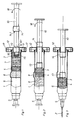
Im folgenden wird die Erfindung an einem in der Zeichnung dargestellten Ausführungsbeispiel näher erläutert; es zeigen:
- Fig. 1
- einen Querschnitt durch eine Spritze in ihrer Ausgangsstellung,
- Fig. 2
- eine der Fig. 1 entsprechende Darstellung, jedoch in der Gebrauchstellung zur Lösung des Wirkstoffs in dem Lösungsmittel,
- Fig. 3
- den Gegenstand nach Fig. 1, jedoch in der für die Applikation des pharmazeutischen Wirkstoffs vorbereiteten Anwendungsstellung.
- Fig. 1
- a cross section through a syringe in its initial position,
- Fig. 2
- a representation corresponding to FIG. 1, but in the use position for dissolving the active ingredient in the solvent,
- Fig. 3
- 1, but in the application position prepared for the application of the active pharmaceutical ingredient.
Die in der Zeichnung dargestellte Spritze für medizinische Zwecke besteht aus einem Spritzenzylinder 1, der an seinem einen Ende zum Ansatz einer Injektionsnadel 2 eingerichtet ist. Im Spritzenzylinder 1 ist ein verschiebbarer Spritzenkolben 3 sowie ein Stopfen 4 vorgesehen, der zwischen dem Nadelansatzende 5 und dem Spritzenkolben 3 angeordnet ist und so das Innere des Spritzenzylinders 1 in zwei Kammern 6, 7 einer Zweikammerspritze unterteilt.The syringe for medical purposes shown in the drawing consists of a syringe cylinder 1, which is set up at one end for the attachment of an
In der nadelseitigen Kammer 6 ist die Mantelfläche des Spritzenzylinders 1 mit einer sich axial erstreckenden, einen By-pass 8 bildenden Querschnittserweiterung versehen. Über diesen By-pass 8 sind die beiden Kammern 6, 7 bei in den Bereich des By-passes 8 verstelltem Stopfen 4 miteinander verbunden.In the needle-
An dem dem Nadelansatzende 5 entgegen gesetzten Zylinderende ist ein Dämpfungsteil 9 vorgesehen, das die Verstellgeschwindigkeit der Kolbenstange 10 begrenzt. Im einzelnen ist dieses Dämpfungsteil 9 von einer Fingerauflage 12 gebildet, die auf einem Glaswulst 11 auf der dem Nadelansatzende 5 abgewandten Seite des Spritzenzylinders 1 aufgesetzt ist. Die Fingerauflage 12 ist mit einem zum Spritzenzylinder 1 koaxialen Innengewinde versehen, das zu einem an der Kolbenstange 10 angeordneten Gewindeschaft 13 korrespondiert. Dabei ist die Länge dem Gewindeschaftes 13 so bemessen, daß durch das Hindurchschrauben dieses Gewindeschaftes 13 durch das Innengewinde der Stopfen 4 gerade in den Bereich des By-passes 8 verstellt wird.At the cylinder end opposite the
Mit Abstand von dem ersten Gewindeschaft 13 weist die Kolbenstange 10 einen zweiten Gewindeschaft 14 auf, der ebenfalls zu dem Innengewinde der Fingerauflage 12 korrespondiert. Die beiden einander zugewandten Stirnflächen 13.1, 14.1 des ersten bzw. des zweiten Gewindeschaftes 13, 14 bilden jeweils einen vorderen bzw. hinteren Anschlag an dem Innengewinde, erlauben also eine Hin- und Herbewegung der Kolbenstange 10 innerhalb des durch die beiden Anschläge festgelegten Verstellhubes. Hierdurch besteht die Möglichkeit, das Lösungsmittel bei dem ersten Verstellhub in Richtung zum nadelseitigen Ende hin in die den Wirkstoff enthaltende Kammer 6 zu überführen und durch anschließendes Zurückziehen der Kolbenstange 10 den Wirkstoff zusammen mit dem Lösungsmittel über den By-pass 8 in die andere Kammer 7 zu überführen. Durch das u. U. mehrfache Überführen der Injektionslösung über den By-pass 8 wird eine relativ schnelle und zuverlässige Auflösung auch solcher Wirkstoffe und Substanzen erreicht, die sich in dem Lösungsmittel vergleichsweise schlecht lösen.At a distance from the first threaded
Die beiderseitigen Anschläge stellen dabei einerseits sicher, daß der Stopfen 4 nicht auf dem Bereich des By-passes 8 herausgedrückt werden kann und gewährleisten andererseits, daß die Kolbenstange 10 mit dem Spritzenkolben 3 nicht versehentlich aus dem Spritzenzylinder 1 herausgezogen werden kann.The stops on both sides ensure on the one hand that the
Nach vollständiger Auflösung des Wirkstoffs in dem Lösungsmittel wird bei zurückgezogenem Spritzenkolben 3 die Kanüle 2 auf das Spritzenansatzende 5 aufgesetzt, anschließend die Kolbenstange 10 gegen den vorderen Anschlag 14.1 verstellt und sodann der zweite Gewindeschaft 14 durch das Innengewinde in der durch den Pfeil 18 angedeuteten Weise hindurchgedreht, worauf sich die Spritze in der in Fig. 3 dargestellten, für die Applikation vorbereiteten Stellung befindet.After the active substance has completely dissolved in the solvent, the
Zur Erleichterung der Montage der Kolbenstange 10 weist diese stirnseitig einen Gewindeansatz 15 für ein im Spritzenkolben 3 vorgesehenes Stopfengewinde auf, wobei zwischen dem Gewindeansatz 15 und dem ersten Gewindeschaft 13 ein zylindrisches Führungsstück 16 vorgesehen ist, dessen Durchmesser nur geringfügig kleiner als der Kerndurchmesser des Innengewindes ist.To facilitate the assembly of the
Die Fingerauflage 12 ist von zwei Schalenhälften gebildet, die zwischen sich den Glaswulst 11 des Spritzenzylinders 1 aufnehmen. Die beiden Schalenhälften sind jeweils mit gegenseitig einrastenden, in der Zeichnung nur angedeuteten Verbindungselementen 17 versehen, wobei die kanülenseitige Schalenhälfte mit einer den Spritzenzylinder 1 umschließenden Ausnehmung und die andere Schalenhälfte mit dem Innengewinde versehen ist. Hierdurch besteht auch die Möglichkeit, die Fingerauflage 12 erst kurz vor der Vorbereitung und Anwendung der Fertigspritze an dieser anzubringen. Eine weitere Vereinfachung der Handhabung läßt sich dadurch erreichen, daß die beiden Schalenhälften randseitig gelenkig miteinander verbunden sind.The
Claims (8)
- A method of intermixing a pharmaceutical substance which is contained in a double-chamber syringe and rose active material is disposed in dry form in the one chamber (6) which is towards the needle, and whose solvent is disposed in the other chamber (7), wherein the two chambers (6, 7) are separated from each other by a plug (4) which for intermixing of the substance with the solvent prior to application is displaceable into the region of a by-pass (8) which is provided in the syringe cylinder (1) and which extends in the axial direction thereof and whose length is greater than the axial dimension of the plug (4), wherein the plug (4) is displaced towards the needle end by way of the syringe plunger (3) which delimits the second chamber (7) and which is provided with a plunger rod (10), directly or by way of the solvent, characterised in that when the syringe is arranged vertically with the needle attachment end (5) pointing upwardly, firstly the plug (4) is displaced into the region of the by-pass (8) at a speed which is limited by apparatus considerations, that then the syringe plunger (3) is put into a condition of bearing against the plug (4) by virtue of free displaceability of the plunger rod (10) towards a front stop (14.1) and thereby the solvent is transferred into the chamber (6) at the needle side, that then the syringe plunger (3) is withdrawn again as far as a rear stop (13.1) on the plunger rod (10) and then displaced again to the front stop (14.1) so that the active material with the solvent flows back from the front chamber (6) by way of the by-pass (8) into the rear chamber (7) and then into the front chamber (6) again one or more times, until the substance is completely dissolved, and that finally after the active material is completely dissolved the front stop (14.1) on the plunger rod (10), which initially restricts the displacement of the syringe plunger (3) towards the needle end of the syringe cylinder (1) is released for application of the pharmaceutical substance.
- A method according to claim 1 characterised in that the needle (2) is fitted when the plunger rod (10) is moved against the rear stop (13.1).
- A syringe for medical purposes for carrying out the method according to claims 1 and 2 comprising a syringe cylinder (1) which is adapted at one end for attachment of an injection needle (2), and a syringe plunger (3) which is displaceable in the syringe cylinder (1), and a plug (4) which is disposed between the needle attachment end (5) and the syringe plunger (3) and thus forms two chambers (6, 7) of a double-chamber syringe, wherein in the chamber (6) which is towards the needle the peripheral surface of the syringe cylinder (1) is provided with an axially extending cross-sectional enlargement which forms a by-pass (8) and by way of which both chambers (6, 7) are communicated with each other when the plug is displaced into the region (8) of the by-pass (5), and further comprising a damping member (9) which serves as a plunger brake at the end of the cylinder which is opposite to the needle attachment end (5), characterised in that the damping member (9) restricts the speed of displacement of the plunger rod (10) until the plug (4) is displaced into the region of the by-pass (8) and that the plunger rod (10), for restricting the displacement stroke movement of the syringe plunger (3) between its starting position at the end of the cylinder and its condition of bearing against the plug (4) when displaced into the by-pass region, has a front stop (14.1) and a rear stop (13.1) for a co-operating portion provided at the end of the cylinder, and that the front stop (14.1) which restricts the displacement of the syringe plunger (3) towards the needle end is releasable.
- A syringe according to claim 3 characterised in that the damping member (9) is formed with a finger support (12) which is fitted on a glass flange (11) on the side of the syringe cylinder (1) which is remote from the needle attachment end (5), and is provided with a female screwthread which is coaxial with respect to the syringe cylinder (1) for a screwthreaded shank (13) disposed on the plunger rod (10), wherein the female screwthread from the co-operating portion and the end face which is remote from the syringe cylinder forms the rear stop, and the length of the screwthreaded shank (13) is such that its end face which is remote from the syringe plunger (3) comes out of the female screwthread as soon as the plug (4) is in the middle region of the by-pass (8).
- A syringe according to claim 4 characterised in that the front stop (14.1) is formed by the end face, which is towards the first screwthreaded shank (13), of a second screwthreaded shank (14) which also corresponds to the female screwthread.
- A syringe according to claim 4 or claim 5 characterised in that the plunger rod (10) is provided at its end with a thread attachment (15) for a plug screwthread in the syringe plunger (3), wherein provided between the thread attachment (15) and the first screwthreaded shank (13) is a cylindrical guide portion (16) whose diameter is only slightly smaller than the minor thread diameter of the female screwthread.
- A syringe according to claims 4 to 6 characterised in that the finger support (12) is formed by two shell halves which accommodate the glass flange (11) of the syringe cylinder (1) between them and which are provided with mutually engaging connecting elements (17), wherein the shell half which is towards the needle end is provided with an opening which embraces the syringe cylinder (1) and the other shell half is provided with the female screwthread.
- A syringe according to claim 7 characterised in that the two shell halves are hingedly connected to each other at the edges.
Priority Applications (7)
| Application Number | Priority Date | Filing Date | Title |
|---|---|---|---|
| DE9090102373T DE59001705D1 (en) | 1990-02-07 | 1990-02-07 | DOUBLE CHAMBER SYRINGE AND METHOD OF USE. |
| DK90102373.9T DK0440846T3 (en) | 1990-02-07 | 1990-02-07 | Double chamber syringe and application method |
| EP90102373A EP0440846B1 (en) | 1990-02-07 | 1990-02-07 | Two-compartment syringe and application process |
| ES199090102373T ES2042093T3 (en) | 1990-02-07 | 1990-02-07 | DOUBLE CHAMBER SYRINGE AND EMPLOYMENT PROCEDURE. |
| AT90102373T ATE90211T1 (en) | 1990-02-07 | 1990-02-07 | TWIN-CHAMBER SYRINGE AND METHOD OF USE. |
| US07/533,448 US5080649A (en) | 1990-02-07 | 1990-06-05 | Dual-compartment hypodermic syringe |
| JP3015297A JP2514472B2 (en) | 1990-02-07 | 1991-02-06 | Method for mixing drug substance filled in a two-chamber syringe and syringe for carrying out this method |
Applications Claiming Priority (1)
| Application Number | Priority Date | Filing Date | Title |
|---|---|---|---|
| EP90102373A EP0440846B1 (en) | 1990-02-07 | 1990-02-07 | Two-compartment syringe and application process |
Publications (2)
| Publication Number | Publication Date |
|---|---|
| EP0440846A1 EP0440846A1 (en) | 1991-08-14 |
| EP0440846B1 true EP0440846B1 (en) | 1993-06-09 |
Family
ID=8203602
Family Applications (1)
| Application Number | Title | Priority Date | Filing Date |
|---|---|---|---|
| EP90102373A Expired - Lifetime EP0440846B1 (en) | 1990-02-07 | 1990-02-07 | Two-compartment syringe and application process |
Country Status (7)
| Country | Link |
|---|---|
| US (1) | US5080649A (en) |
| EP (1) | EP0440846B1 (en) |
| JP (1) | JP2514472B2 (en) |
| AT (1) | ATE90211T1 (en) |
| DE (1) | DE59001705D1 (en) |
| DK (1) | DK0440846T3 (en) |
| ES (1) | ES2042093T3 (en) |
Cited By (3)
| Publication number | Priority date | Publication date | Assignee | Title |
|---|---|---|---|---|
| US5728075A (en) * | 1993-10-29 | 1998-03-17 | Pharmacia & Upjohn Aktiebolag | Injection devices |
| EP0830868A2 (en) * | 1996-09-23 | 1998-03-25 | Arzneimittel GmbH Apotheker Vetter & Co. Ravensburg | Prefilled syringe for medical purpose |
| US7998106B2 (en) | 2004-05-03 | 2011-08-16 | Thorne Jr Gale H | Safety dispensing system for hazardous substances |
Families Citing this family (130)
| Publication number | Priority date | Publication date | Assignee | Title |
|---|---|---|---|---|
| US6540154B1 (en) * | 1991-04-24 | 2003-04-01 | Aerogen, Inc. | Systems and methods for controlling fluid feed to an aerosol generator |
| JPH0531190A (en) * | 1991-07-26 | 1993-02-09 | Seikagaku Kogyo Co Ltd | Injector |
| US5211285A (en) * | 1992-03-19 | 1993-05-18 | Habley Medical Technology Corporation | Telescoping, pharmaceutical mixing container |
| AU665067B2 (en) * | 1992-04-30 | 1995-12-14 | Takeda Pharmaceutical Company Limited | Prefilled syringe |
| JP3471318B2 (en) * | 1992-11-27 | 2003-12-02 | 株式会社大協精工 | Syringe and container |
| US5364386A (en) * | 1993-05-05 | 1994-11-15 | Hikari Seiyaku Kabushiki Kaisha | Infusion unit |
| SE9303453D0 (en) * | 1993-10-20 | 1993-10-20 | Kabi Pharmacia Ab | Injection cartridge |
| US5586975A (en) * | 1994-02-18 | 1996-12-24 | Takeda Chemical Industries. Ltd. | Air and liquid tight container with a slidable gasket |
| US6205999B1 (en) | 1995-04-05 | 2001-03-27 | Aerogen, Inc. | Methods and apparatus for storing chemical compounds in a portable inhaler |
| US5758637A (en) | 1995-08-31 | 1998-06-02 | Aerogen, Inc. | Liquid dispensing apparatus and methods |
| US6782886B2 (en) | 1995-04-05 | 2004-08-31 | Aerogen, Inc. | Metering pumps for an aerosolizer |
| AU3186297A (en) * | 1996-07-05 | 1998-02-02 | Debiotech S.A. | Dual-chamber syringe for mixing two substances prior to injection |
| JP3949752B2 (en) * | 1996-07-29 | 2007-07-25 | 日本ケミカルリサーチ株式会社 | Syringe with drug dissolution mechanism |
| US5865804A (en) * | 1997-07-16 | 1999-02-02 | Bachynsky; Nicholas | Rotary cam syringe |
| US5971953A (en) * | 1998-01-09 | 1999-10-26 | Bachynsky; Nicholas | Dual chamber syringe apparatus |
| US6149626A (en) * | 1997-10-03 | 2000-11-21 | Bachynsky; Nicholas | Automatic injecting syringe apparatus |
| US6681475B2 (en) | 1998-04-20 | 2004-01-27 | Becton Dickinson And Company | Method of sealing a medical container with a plastic closure |
| US6378714B1 (en) | 1998-04-20 | 2002-04-30 | Becton Dickinson And Company | Transferset for vials and other medical containers |
| DE19821933C1 (en) * | 1998-05-15 | 1999-11-11 | Disetronic Licensing Ag | Device for administering an injectable product |
| US6907679B2 (en) | 1998-11-12 | 2005-06-21 | Qlt Usa, Inc. | Method for lyophilizing an active agent |
| DE19912322A1 (en) | 1999-03-19 | 2000-09-28 | Vetter & Co Apotheker | Syringe for medical purposes |
| SE9901366D0 (en) | 1999-04-16 | 1999-04-16 | Pharmacia & Upjohn Ab | Injector device and method for its operation |
| US6331173B1 (en) | 1999-04-20 | 2001-12-18 | Pharmacia Ab | Device for displacing a member in a container |
| US6235177B1 (en) * | 1999-09-09 | 2001-05-22 | Aerogen, Inc. | Method for the construction of an aperture plate for dispensing liquid droplets |
| EP1225938B1 (en) | 1999-10-22 | 2007-12-19 | Antares Pharma, Inc. | Medicament cartridge and injection device |
| DE60133723T2 (en) * | 2000-02-28 | 2009-07-02 | PharmaKodex Ltd., Chippenham | ADMINISTRATION SYSTEMS FOR ORAL MEDICINAL PRODUCTS TO BE USED |
| FR2806916B1 (en) * | 2000-03-31 | 2002-11-29 | Sedat | INJECTION SYRINGE OF AN EXTEMPORANEOUS MIXTURE |
| US7600511B2 (en) * | 2001-11-01 | 2009-10-13 | Novartis Pharma Ag | Apparatus and methods for delivery of medicament to a respiratory system |
| US7971588B2 (en) * | 2000-05-05 | 2011-07-05 | Novartis Ag | Methods and systems for operating an aerosol generator |
| US7100600B2 (en) | 2001-03-20 | 2006-09-05 | Aerogen, Inc. | Fluid filled ampoules and methods for their use in aerosolizers |
| US8336545B2 (en) * | 2000-05-05 | 2012-12-25 | Novartis Pharma Ag | Methods and systems for operating an aerosol generator |
| MXPA02010884A (en) * | 2000-05-05 | 2003-03-27 | Aerogen Ireland Ltd | Apparatus and methods for the delivery of medicaments to the respiratory system. |
| US6948491B2 (en) * | 2001-03-20 | 2005-09-27 | Aerogen, Inc. | Convertible fluid feed system with comformable reservoir and methods |
| CA2412420C (en) | 2000-06-08 | 2008-12-02 | Meridian Medical Technologies, Inc. | Wet/dry automatic injector assembly |
| US6543443B1 (en) | 2000-07-12 | 2003-04-08 | Aerogen, Inc. | Methods and devices for nebulizing fluids |
| DE10036594A1 (en) * | 2000-07-27 | 2002-02-07 | Pfeiffer Erich Gmbh & Co Kg | Delivery unit, especially for pharmaceuticals, comprises a container composed of separate chambers which hold a media component, an actuating unit and a connection between the chambers |
| US7544189B2 (en) * | 2000-10-10 | 2009-06-09 | Meridian Medical Technologies, Inc. | Needle and hub assembly for automatic injector |
| US7621887B2 (en) | 2000-10-10 | 2009-11-24 | Meridian Medical Technologies, Inc. | Wet/dry automatic injector assembly |
| US6656150B2 (en) * | 2000-10-10 | 2003-12-02 | Meridian Medical Technologies, Inc. | Wet/dry automatic injector assembly |
| US6641561B1 (en) | 2000-10-10 | 2003-11-04 | Meridian Medical Technologies, Inc. | Drug delivery device |
| US7556614B2 (en) * | 2000-10-10 | 2009-07-07 | Meridian Medical Technologies, Inc. | Separation assembly for drug delivery device |
| US6546927B2 (en) | 2001-03-13 | 2003-04-15 | Aerogen, Inc. | Methods and apparatus for controlling piezoelectric vibration |
| US6550472B2 (en) | 2001-03-16 | 2003-04-22 | Aerogen, Inc. | Devices and methods for nebulizing fluids using flow directors |
| US6554201B2 (en) | 2001-05-02 | 2003-04-29 | Aerogen, Inc. | Insert molded aerosol generator and methods |
| US6732944B2 (en) * | 2001-05-02 | 2004-05-11 | Aerogen, Inc. | Base isolated nebulizing device and methods |
| DE10140704A1 (en) * | 2001-08-18 | 2003-03-06 | Vetter & Co Apotheker | Process for mixing a poorly soluble pharmaceutical substance with a solvent and syringe to apply the process |
| US20050205089A1 (en) * | 2002-01-07 | 2005-09-22 | Aerogen, Inc. | Methods and devices for aerosolizing medicament |
| US7360536B2 (en) | 2002-01-07 | 2008-04-22 | Aerogen, Inc. | Devices and methods for nebulizing fluids for inhalation |
| US7677467B2 (en) * | 2002-01-07 | 2010-03-16 | Novartis Pharma Ag | Methods and devices for aerosolizing medicament |
| JP4761709B2 (en) * | 2002-01-15 | 2011-08-31 | エアロジェン,インコーポレイテッド | Method and system for operating an aerosol generator |
| KR20040103930A (en) | 2002-02-11 | 2004-12-09 | 앤태어스 파머, 인코퍼레이티드 | Intradermal injector |
| EP1476211B1 (en) * | 2002-02-15 | 2015-06-24 | Antares Pharma, Inc. | Injector with bypass channel |
| US20070044792A1 (en) * | 2005-08-30 | 2007-03-01 | Aerogen, Inc. | Aerosol generators with enhanced corrosion resistance |
| ES2572770T3 (en) * | 2002-05-20 | 2016-06-02 | Novartis Ag | Apparatus for providing spray for medical treatment and methods |
| DE10254321A1 (en) * | 2002-11-21 | 2004-06-17 | Arzneimittel Gmbh Apotheker Vetter & Co. Ravensburg | Pre-filled syringe |
| US7678333B2 (en) * | 2003-01-22 | 2010-03-16 | Duoject Medical Systems Inc. | Fluid transfer assembly for pharmaceutical delivery system and method for using same |
| EP1592381B1 (en) * | 2003-01-22 | 2010-04-28 | Duoject Medical Systems Inc | Pharmaceutical delivery systems |
| US7699804B2 (en) * | 2003-01-31 | 2010-04-20 | Creare Inc. | Fluid ejection system |
| US8616195B2 (en) * | 2003-07-18 | 2013-12-31 | Novartis Ag | Nebuliser for the production of aerosolized medication |
| CA2560742A1 (en) | 2004-03-23 | 2005-10-06 | Biogen Idec Ma Inc. | Receptor coupling agents and therapeutic uses thereof |
| US7290541B2 (en) * | 2004-04-20 | 2007-11-06 | Aerogen, Inc. | Aerosol delivery apparatus and method for pressure-assisted breathing systems |
| US7267121B2 (en) * | 2004-04-20 | 2007-09-11 | Aerogen, Inc. | Aerosol delivery apparatus and method for pressure-assisted breathing systems |
| US7946291B2 (en) | 2004-04-20 | 2011-05-24 | Novartis Ag | Ventilation systems and methods employing aerosol generators |
| JP5175090B2 (en) * | 2004-04-20 | 2013-04-03 | ノバルティス アーゲー | Submersible breathing system |
| US6997910B2 (en) * | 2004-05-03 | 2006-02-14 | Infusive Technologies, Llc | Multi-chamber, sequential dose dispensing syringe |
| US7101354B2 (en) | 2004-05-03 | 2006-09-05 | Infusive Technologies, Llc | Mixing syringe with and without flush |
| US7731678B2 (en) | 2004-10-13 | 2010-06-08 | Hyprotek, Inc. | Syringe devices and methods for mixing and administering medication |
| DE102004056617A1 (en) | 2004-11-24 | 2006-06-01 | Arthur Fabian | Medical double-chamber syringe made of plastic |
| US20060178641A1 (en) * | 2004-12-03 | 2006-08-10 | Reynolds David L | Extensible plunger rod for pharmaceutical delivery device |
| US20060144869A1 (en) * | 2004-12-30 | 2006-07-06 | Chang Byeong S | Container closure delivery system |
| US7959600B2 (en) * | 2004-12-30 | 2011-06-14 | Byeong S. Chang | Container closure delivery system |
| US20060157507A1 (en) * | 2004-12-30 | 2006-07-20 | Chang Byeong S | Multi-functional container closure delivery system |
| BRPI0614025A2 (en) | 2005-01-24 | 2012-12-25 | Antares Pharma Inc | jet injectors |
| CA2762072C (en) * | 2005-02-01 | 2017-08-29 | Intelliject, Inc. | Devices, systems, and methods for medicament delivery |
| US20080208137A1 (en) * | 2005-05-16 | 2008-08-28 | Fago Frank M | Multi-Stage Sryinge and Methods of Using the Same |
| US9108211B2 (en) * | 2005-05-25 | 2015-08-18 | Nektar Therapeutics | Vibration systems and methods |
| CA2626864C (en) | 2005-11-09 | 2015-06-02 | Hyprotek, Inc. | Syringe devices, components of syringe devices, and methods of forming components and syringe devices |
| JP4834389B2 (en) * | 2005-11-29 | 2011-12-14 | 前田産業株式会社 | Injection device |
| US8251947B2 (en) | 2006-05-03 | 2012-08-28 | Antares Pharma, Inc. | Two-stage reconstituting injector |
| EP1894590B1 (en) * | 2006-08-30 | 2012-04-25 | Roche Diagnostics GmbH | Injection device with simplified retaining of a stopper |
| FR2905682B1 (en) * | 2006-09-13 | 2011-05-20 | Becton Dickinson France | CONTAINER, MEDICAL DEVICE AND METHOD FOR CONTAINING AND EXPULTING A PRODUCT. |
| BRPI0808709A2 (en) * | 2007-03-09 | 2014-09-09 | Lilly Co Eli | MECHANISM FOR AUTOMATIC INJECTION DEVICE |
| US9522097B2 (en) | 2007-10-04 | 2016-12-20 | Hyprotek, Inc. | Mixing/administration syringe devices, protective packaging and methods of protecting syringe handlers |
| US8002737B2 (en) | 2007-10-04 | 2011-08-23 | Hyprotek, Inc. | Mixing/administration syringe devices, protective packaging and methods of protecting syringe handlers |
| RU2487728C2 (en) * | 2007-11-22 | 2013-07-20 | Биовитрум Аб (Пабл) | Method and device for sequential delivery of two fluid flows comprising partition |
| WO2009105905A1 (en) * | 2008-02-28 | 2009-09-03 | Medmix Systems Ag | Single chamber device for drawing in and dispensing components |
| DE102008030268B3 (en) | 2008-06-19 | 2010-02-04 | Arzneimittel Gmbh Apotheker Vetter & Co. Ravensburg | Method for filling dual-chamber systems in pre-sterilizable carrier systems and pre-sterilisable carrier system |
| DE102008030267B3 (en) * | 2008-06-19 | 2010-01-28 | Arzneimittel Gmbh Apotheker Vetter & Co. Ravensburg | Method for filling dual-chamber systems in pre-sterilizable carrier systems and pre-sterilisable carrier system |
| JP5611208B2 (en) | 2008-08-05 | 2014-10-22 | アンタレス・ファーマ・インコーポレーテッド | Multiple dose injection device |
| US9061107B2 (en) * | 2008-09-18 | 2015-06-23 | Becton, Dickinson and Comapany | Needle mounting feature for ensuring proper reconstitution sequence |
| AU2010226442A1 (en) | 2009-03-20 | 2011-10-13 | Antares Pharma, Inc. | Hazardous agent injection system |
| US20100274185A1 (en) * | 2009-04-28 | 2010-10-28 | Thomas Chun | Automatic injection syringe assembly |
| EP2424595A2 (en) * | 2009-04-30 | 2012-03-07 | Hyperbranch Medical Technology, Inc. | Self-contained medical applicators for surgical sealants, and methods of use thereof |
| US20100324480A1 (en) * | 2009-06-17 | 2010-12-23 | Thomas Chun | Automatic injection syringe assembly |
| PL2542280T3 (en) | 2010-03-01 | 2015-02-27 | Lilly Co Eli | Automatic injection device with delay mechanism including dual functioning biasing member |
| EP2550046B1 (en) | 2010-03-23 | 2019-04-24 | Hyperbranch Medical Technology, Inc. | Disposable syringe applicators for multi-component formulations |
| WO2012010852A2 (en) * | 2010-07-22 | 2012-01-26 | Kevin Abbott | Fluid dose dispensing apparatus |
| JP4757951B1 (en) * | 2010-10-19 | 2011-08-24 | 株式会社アルテ | Two-chamber syringe |
| AR083884A1 (en) * | 2010-11-16 | 2013-03-27 | Otsuka Pharma Co Ltd | DOUBLE CHAMBER AND FILLING SYRINGE OF ARIPIPRAZOL IN THE SYRINGE |
| EP2663275B1 (en) | 2011-01-10 | 2017-03-08 | Byeong Seon Chang | Compact medication reconstitution device and method |
| US9084849B2 (en) | 2011-01-26 | 2015-07-21 | Kaleo, Inc. | Medicament delivery devices for administration of a medicament within a prefilled syringe |
| US10092688B2 (en) | 2011-05-13 | 2018-10-09 | Laura Jean Robinson | Medicament kit and method of use |
| US8496619B2 (en) | 2011-07-15 | 2013-07-30 | Antares Pharma, Inc. | Injection device with cammed ram assembly |
| US9220660B2 (en) | 2011-07-15 | 2015-12-29 | Antares Pharma, Inc. | Liquid-transfer adapter beveled spike |
| CN104487114A (en) | 2012-04-06 | 2015-04-01 | 安塔雷斯药品公司 | Needle assisted jet injection administration of testosterone compositions |
| WO2013169800A1 (en) | 2012-05-07 | 2013-11-14 | Antares Pharma, Inc. | Injection device with cammed ram assembly |
| US9522235B2 (en) | 2012-05-22 | 2016-12-20 | Kaleo, Inc. | Devices and methods for delivering medicaments from a multi-chamber container |
| US9731076B2 (en) * | 2012-06-29 | 2017-08-15 | Ethicon, Inc. | Multi-compartment pre-filled mixing syringes with bypass |
| EP2953667B1 (en) | 2013-02-11 | 2019-10-23 | Antares Pharma, Inc. | Needle assisted jet injection device having reduced trigger force |
| WO2014164786A1 (en) | 2013-03-11 | 2014-10-09 | Madsen Patrick | Dosage injector with pinion system |
| EP2968766B1 (en) | 2013-03-14 | 2022-08-10 | Eli Lilly and Company | Delay mechanism suitable for compact automatic injection device |
| US9913943B2 (en) | 2013-03-14 | 2018-03-13 | Eli Lilly And Company | Trigger assembly for an automatic injection device |
| WO2015153828A1 (en) | 2014-04-04 | 2015-10-08 | Hyperbranch Medical Technology, Inc. | Extended tip spray applicator for two-component surgical selant, and methods of use thereof |
| US10201692B2 (en) | 2014-09-09 | 2019-02-12 | Byeong Seon Chang | Solution delivery device and method |
| KR102450956B1 (en) * | 2014-12-30 | 2022-10-04 | 쓰리엠 이노베이티브 프로퍼티즈 컴파니 | Containers for mixing and dispensing ingredients |
| EP3240592B1 (en) | 2014-12-30 | 2023-08-09 | Kindeva Drug Delivery L.P. | Container for mixing and dispensing two components |
| AU2015374319B2 (en) | 2014-12-30 | 2019-01-03 | Kindeva Drug Delivery L.P. | Container for mixing and dispensing fluid medication components |
| CA2980004C (en) | 2015-03-24 | 2023-10-10 | Kaleo, Inc. | Devices and methods for delivering a lyophilized medicament |
| CN107835700A (en) | 2015-06-30 | 2018-03-23 | Kaleo公司 | For the automatic injector for the medicament being applied in pre-filled syringe |
| CH711657A2 (en) * | 2015-10-19 | 2017-04-28 | Tecpharma Licensing Ag | Device for administering an active substance and method for operating this device. |
| CH711656A2 (en) * | 2015-10-19 | 2017-04-28 | Tecpharma Licensing Ag | Device for administering an active substance and method for operating this device. |
| CH711655A2 (en) * | 2015-10-19 | 2017-04-28 | Tecpharma Licensing Ag | Device for administering an active substance and method for operating this device. |
| AR107541A1 (en) | 2016-02-05 | 2018-05-09 | Tolmar Therapeutics Inc | VENTILATED COATING PLATE FOR A SYRINGE SET |
| WO2017191641A1 (en) * | 2016-05-04 | 2017-11-09 | Zelikman, Zarema | A mixing apparatus and method thereof |
| FR3050984B1 (en) * | 2016-05-04 | 2020-05-15 | Aptar France Sas | FLUID PRODUCT DISPENSING DEVICE. |
| FR3055807B1 (en) | 2016-09-15 | 2019-08-16 | Edix Sa | CONNECTOR-SYRINGE DEVICE FOR ADMINISTERING AT LEAST TWO PRODUCTS IN QUANTITIES CONTROLLED AND IN ONE INJECTION |
| EP3655067A1 (en) * | 2017-07-17 | 2020-05-27 | Baxter International, Inc. | Medical syringe system with filtered filling port |
| USD908916S1 (en) | 2018-06-19 | 2021-01-26 | Tolmar Therapeutics, Inc. | Syringe restrictor plate |
| AU2020331302A1 (en) | 2019-08-09 | 2022-01-06 | Kaleo, Inc. | Devices and methods for delivery of substances within a prefilled syringe |
| CN110960268B (en) * | 2020-01-06 | 2023-04-21 | 北京新希望六和生物科技产业集团有限公司 | Tissue minimally invasive sampler for livestock |
Family Cites Families (15)
| Publication number | Priority date | Publication date | Assignee | Title |
|---|---|---|---|---|
| US2591046A (en) * | 1948-10-18 | 1952-04-01 | Frederick M Turnbull | Hypodermic syringe assembly |
| US2549417A (en) * | 1949-08-10 | 1951-04-17 | Frederick M Turnbull | Syringe ampoule |
| GB1214053A (en) * | 1968-02-05 | 1970-12-02 | Hans Wimmer | Improvements in or relating to two chamber injection ampoules |
| JPS55116620U (en) * | 1979-02-13 | 1980-08-18 | ||
| US4226236A (en) * | 1979-05-07 | 1980-10-07 | Abbott Laboratories | Prefilled, vented two-compartment syringe |
| US4312343A (en) * | 1979-07-30 | 1982-01-26 | Leveen Harry H | Syringe |
| US4583974A (en) * | 1984-04-04 | 1986-04-22 | Kokernak Denis T | Syringe for balloon dilation catheters |
| US4599082A (en) * | 1984-08-13 | 1986-07-08 | Becton, Dickinson And Company | Two-component syringe assembly |
| DE3687530T2 (en) * | 1985-06-27 | 1993-07-22 | Duphar Int Res | SYRINGE. |
| US4613326A (en) * | 1985-07-12 | 1986-09-23 | Becton, Dickinson And Company | Two-component medication syringe assembly |
| EP0295337B1 (en) * | 1987-06-16 | 1991-12-04 | Akzo Nobel N.V. | Two compartment syringe and method of manufacturing |
| IL86799A (en) * | 1987-07-02 | 1993-03-15 | Kabi Pharmacia Ab | Method and device for injection |
| GB8723454D0 (en) * | 1987-10-06 | 1987-11-11 | Beecham Group Plc | Device |
| ES2024564B3 (en) * | 1988-02-16 | 1992-03-01 | Arzneimittel Gmbh Apotheker Vetter & Co Ravensburg | SYRINGE FOR MEDICINAL PURPOSES |
| FR2634650B1 (en) * | 1988-08-01 | 1990-11-02 | Labouze Joseph | NON REUSABLE SYRINGE |
-
1990
- 1990-02-07 AT AT90102373T patent/ATE90211T1/en not_active IP Right Cessation
- 1990-02-07 DE DE9090102373T patent/DE59001705D1/en not_active Expired - Lifetime
- 1990-02-07 EP EP90102373A patent/EP0440846B1/en not_active Expired - Lifetime
- 1990-02-07 DK DK90102373.9T patent/DK0440846T3/en active
- 1990-02-07 ES ES199090102373T patent/ES2042093T3/en not_active Expired - Lifetime
- 1990-06-05 US US07/533,448 patent/US5080649A/en not_active Expired - Lifetime
-
1991
- 1991-02-06 JP JP3015297A patent/JP2514472B2/en not_active Expired - Lifetime
Cited By (4)
| Publication number | Priority date | Publication date | Assignee | Title |
|---|---|---|---|---|
| US5728075A (en) * | 1993-10-29 | 1998-03-17 | Pharmacia & Upjohn Aktiebolag | Injection devices |
| EP0830868A2 (en) * | 1996-09-23 | 1998-03-25 | Arzneimittel GmbH Apotheker Vetter & Co. Ravensburg | Prefilled syringe for medical purpose |
| US5833653A (en) * | 1996-09-23 | 1998-11-10 | Arzneimittel Gmbh Apotheker Vetter & Co. Ravensburg | Prefilled hypodermic syringe |
| US7998106B2 (en) | 2004-05-03 | 2011-08-16 | Thorne Jr Gale H | Safety dispensing system for hazardous substances |
Also Published As
| Publication number | Publication date |
|---|---|
| ATE90211T1 (en) | 1993-06-15 |
| JPH04322662A (en) | 1992-11-12 |
| ES2042093T3 (en) | 1993-12-01 |
| DE59001705D1 (en) | 1993-07-15 |
| DK0440846T3 (en) | 1993-07-12 |
| US5080649A (en) | 1992-01-14 |
| EP0440846A1 (en) | 1991-08-14 |
| JP2514472B2 (en) | 1996-07-10 |
Similar Documents
| Publication | Publication Date | Title |
|---|---|---|
| EP0440846B1 (en) | Two-compartment syringe and application process | |
| EP0328699B1 (en) | Syringe for medical use | |
| EP1287841B1 (en) | Method for mixing a poorly soluble pharmaceutical substance with a solvent and syringe for use with said method | |
| DE69628275T2 (en) | Device for transferring liquids from a medicinal bottle to a syringe | |
| DE3823266C2 (en) | Spray ampoule | |
| DE69726531T2 (en) | Lockable protective sleeve for pre-filled syringe | |
| DE1908295C3 (en) | Injection device | |
| DE2046953A1 (en) | Syringe filled through the closure opening and method of filling it | |
| DE1195907B (en) | Needleless injection syringe | |
| EP0652019A1 (en) | Mixing and administration syringe | |
| DE2909002B2 (en) | Single use syringe | |
| WO2009100550A1 (en) | Administering apparatus comprising a blockable actuation element | |
| CH691031A5 (en) | Two-part device for the administration of drugs. | |
| DE2648795A1 (en) | PRE-FILLED, EASILY READY TO USE INJECTION SYRINGE | |
| CH712753A2 (en) | Separating a needle cap from a product container and method of mounting an injection device. | |
| DE69728062T2 (en) | INJECTION SYRINGE WITH A MOVABLE NEEDLE PROTECTION DEVICE | |
| DE19935681A1 (en) | Device for filling a syringe barrel and / or for placing a stopper in the syringe barrel | |
| EP1186312A2 (en) | Dispensing device for substances | |
| DE19938078A1 (en) | Unit for taking a liquid medicament from a container provided with a membrane comprises a movable housing section with a hollow mandrel which in a certain position pierces the membrane | |
| DE2701903A1 (en) | ADDED DRUG SYSTEM | |
| DE4120267A1 (en) | METHOD FOR OPERATING A DEVICE FOR DELIVERING A LIQUID MEDICAL TREATMENT SUBSTANCE TO A BODY TO BE TREATED, AND DEVICE FOR IMPLEMENTING THE METHOD | |
| DE1491850B1 (en) | Injection ampoule | |
| EP1359958B1 (en) | Injection syringe | |
| DE2024117B1 (en) | Injection syringe | |
| CH398890A (en) | Plunger injection syringe |
Legal Events
| Date | Code | Title | Description |
|---|---|---|---|
| PUAI | Public reference made under article 153(3) epc to a published international application that has entered the european phase |
Free format text: ORIGINAL CODE: 0009012 |
|
| 17P | Request for examination filed |
Effective date: 19901116 |
|
| AK | Designated contracting states |
Kind code of ref document: A1 Designated state(s): AT BE CH DE DK ES FR GB GR IT LI LU NL SE |
|
| 17Q | First examination report despatched |
Effective date: 19921201 |
|
| GRAA | (expected) grant |
Free format text: ORIGINAL CODE: 0009210 |
|
| AK | Designated contracting states |
Kind code of ref document: B1 Designated state(s): AT BE CH DE DK ES FR GB GR IT LI LU NL SE |
|
| REF | Corresponds to: |
Ref document number: 90211 Country of ref document: AT Date of ref document: 19930615 Kind code of ref document: T |
|
| ITF | It: translation for a ep patent filed |
Owner name: JACOBACCI CASETTA & PERANI S.P.A. |
|
| REG | Reference to a national code |
Ref country code: DK Ref legal event code: T3 |
|
| REF | Corresponds to: |
Ref document number: 59001705 Country of ref document: DE Date of ref document: 19930715 |
|
| ET | Fr: translation filed | ||
| REG | Reference to a national code |
Ref country code: GR Ref legal event code: FG4A Free format text: 3008324 |
|
| GBT | Gb: translation of ep patent filed (gb section 77(6)(a)/1977) |
Effective date: 19930816 |
|
| REG | Reference to a national code |
Ref country code: ES Ref legal event code: FG2A Ref document number: 2042093 Country of ref document: ES Kind code of ref document: T3 |
|
| EPTA | Lu: last paid annual fee | ||
| PLBE | No opposition filed within time limit |
Free format text: ORIGINAL CODE: 0009261 |
|
| STAA | Information on the status of an ep patent application or granted ep patent |
Free format text: STATUS: NO OPPOSITION FILED WITHIN TIME LIMIT |
|
| 26N | No opposition filed | ||
| EAL | Se: european patent in force in sweden |
Ref document number: 90102373.9 |
|
| REG | Reference to a national code |
Ref country code: GB Ref legal event code: IF02 |
|
| PGFP | Annual fee paid to national office [announced via postgrant information from national office to epo] |
Ref country code: LU Payment date: 20090206 Year of fee payment: 20 Ref country code: AT Payment date: 20090228 Year of fee payment: 20 Ref country code: FR Payment date: 20081113 Year of fee payment: 20 Ref country code: ES Payment date: 20090109 Year of fee payment: 20 Ref country code: DK Payment date: 20090206 Year of fee payment: 20 |
|
| PGFP | Annual fee paid to national office [announced via postgrant information from national office to epo] |
Ref country code: NL Payment date: 20090227 Year of fee payment: 20 |
|
| PGFP | Annual fee paid to national office [announced via postgrant information from national office to epo] |
Ref country code: CH Payment date: 20090218 Year of fee payment: 20 Ref country code: GB Payment date: 20081230 Year of fee payment: 20 Ref country code: GR Payment date: 20081111 Year of fee payment: 20 |
|
| PGFP | Annual fee paid to national office [announced via postgrant information from national office to epo] |
Ref country code: BE Payment date: 20090227 Year of fee payment: 20 |
|
| PGFP | Annual fee paid to national office [announced via postgrant information from national office to epo] |
Ref country code: SE Payment date: 20090213 Year of fee payment: 20 Ref country code: DE Payment date: 20090414 Year of fee payment: 20 Ref country code: IT Payment date: 20090226 Year of fee payment: 20 |
|
| REG | Reference to a national code |
Ref country code: CH Ref legal event code: PL |
|
| REG | Reference to a national code |
Ref country code: DK Ref legal event code: EUP |
|
| BE20 | Be: patent expired |
Owner name: *ARZNEIMITTEL G.M.B.H. APOTHEKER VETTER & CO. RAVE Effective date: 20100207 |
|
| REG | Reference to a national code |
Ref country code: GB Ref legal event code: PE20 Expiry date: 20100206 |
|
| NLV7 | Nl: ceased due to reaching the maximum lifetime of a patent |
Effective date: 20100207 |
|
| REG | Reference to a national code |
Ref country code: ES Ref legal event code: FD2A Effective date: 20100208 |
|
| PG25 | Lapsed in a contracting state [announced via postgrant information from national office to epo] |
Ref country code: GB Free format text: LAPSE BECAUSE OF EXPIRATION OF PROTECTION Effective date: 20100206 |
|
| PG25 | Lapsed in a contracting state [announced via postgrant information from national office to epo] |
Ref country code: ES Free format text: LAPSE BECAUSE OF EXPIRATION OF PROTECTION Effective date: 20100208 |
|
| PG25 | Lapsed in a contracting state [announced via postgrant information from national office to epo] |
Ref country code: DE Free format text: LAPSE BECAUSE OF EXPIRATION OF PROTECTION Effective date: 20100207 |