EP0439680A2 - Method of and device for transporting items along a production line - Google Patents
Method of and device for transporting items along a production line Download PDFInfo
- Publication number
- EP0439680A2 EP0439680A2 EP90118926A EP90118926A EP0439680A2 EP 0439680 A2 EP0439680 A2 EP 0439680A2 EP 90118926 A EP90118926 A EP 90118926A EP 90118926 A EP90118926 A EP 90118926A EP 0439680 A2 EP0439680 A2 EP 0439680A2
- Authority
- EP
- European Patent Office
- Prior art keywords
- production
- conveyor
- objects
- area
- areas
- Prior art date
- Legal status (The legal status is an assumption and is not a legal conclusion. Google has not performed a legal analysis and makes no representation as to the accuracy of the status listed.)
- Withdrawn
Links
Images


Classifications
-
- B—PERFORMING OPERATIONS; TRANSPORTING
- B65—CONVEYING; PACKING; STORING; HANDLING THIN OR FILAMENTARY MATERIAL
- B65G—TRANSPORT OR STORAGE DEVICES, e.g. CONVEYORS FOR LOADING OR TIPPING, SHOP CONVEYOR SYSTEMS OR PNEUMATIC TUBE CONVEYORS
- B65G35/00—Mechanical conveyors not otherwise provided for
- B65G35/06—Mechanical conveyors not otherwise provided for comprising a load-carrier moving along a path, e.g. a closed path, and adapted to be engaged by any one of a series of traction elements spaced along the path
-
- B—PERFORMING OPERATIONS; TRANSPORTING
- B23—MACHINE TOOLS; METAL-WORKING NOT OTHERWISE PROVIDED FOR
- B23Q—DETAILS, COMPONENTS, OR ACCESSORIES FOR MACHINE TOOLS, e.g. ARRANGEMENTS FOR COPYING OR CONTROLLING; MACHINE TOOLS IN GENERAL CHARACTERISED BY THE CONSTRUCTION OF PARTICULAR DETAILS OR COMPONENTS; COMBINATIONS OR ASSOCIATIONS OF METAL-WORKING MACHINES, NOT DIRECTED TO A PARTICULAR RESULT
- B23Q7/00—Arrangements for handling work specially combined with or arranged in, or specially adapted for use in connection with, machine tools, e.g. for conveying, loading, positioning, discharging, sorting
- B23Q7/14—Arrangements for handling work specially combined with or arranged in, or specially adapted for use in connection with, machine tools, e.g. for conveying, loading, positioning, discharging, sorting co-ordinated in production lines
- B23Q7/1426—Arrangements for handling work specially combined with or arranged in, or specially adapted for use in connection with, machine tools, e.g. for conveying, loading, positioning, discharging, sorting co-ordinated in production lines with work holders not rigidly fixed to the transport devices
-
- B—PERFORMING OPERATIONS; TRANSPORTING
- B62—LAND VEHICLES FOR TRAVELLING OTHERWISE THAN ON RAILS
- B62D—MOTOR VEHICLES; TRAILERS
- B62D65/00—Designing, manufacturing, e.g. assembling, facilitating disassembly, or structurally modifying motor vehicles or trailers, not otherwise provided for
- B62D65/02—Joining sub-units or components to, or positioning sub-units or components with respect to, body shell or other sub-units or components
- B62D65/18—Transportation, conveyor or haulage systems specially adapted for motor vehicle or trailer assembly lines
Definitions
- the invention relates to a method for transporting objects, in particular workpieces arranged on workpiece carriers, along a production line having at least one production area, and a device according to the preamble of claim 9.
- Production lines serve to chain several production processes.
- at least one production area is integrated into the production line, which in turn preferably comprises several production stations.
- the production stations can be used for processing as well as for assembly, testing or the like of any objects. As a result, there are a large number of successive ones on the production line Processing, assembly or testing processes or combinations thereof.
- the objects to be manufactured that is to be processed, assembled, tested or otherwise treated, are conveyed through the production stations of one or more production areas.
- These objects to be conveyed are usually workpieces arranged on workpiece carriers (pallets).
- workpiece carriers pallets
- Such production lines are usually used in automobile construction, namely for machining or testing engine or transmission parts arranged on workpiece carriers or for assembling the same.
- the object of the invention is to create a method and a device of the type mentioned at the outset, which ensures that the objects are transported further, preferably in a more economical manner, through preferably several production areas.
- a method for solving this problem has the features of claim 1. Characterized in that the objects are transported at a different speed than at least through the manufacturing area or the manufacturing areas than on the remaining sections of the production line, in particular between adjacent manufacturing areas, in the areas of the manufacturing stations, a further transportation of the items adapted to the specific properties thereof can take place .
- the further transport speed of the objects is expediently greater at least through one or more production areas than on the remaining sections of the production line. This reduces the time it takes to move the items from one manufacturing station to another.
- the method according to the invention thus shortens the overall production time. In addition, there is better utilization of the production stations, which results in economical mass production.
- the objects are transported into the respective production area, within the same, ie from the production station to the production station and out of the production area, at a greater speed than on the remaining sections of the production line, namely in particular between adjacent production areas. In this way it is prevented that in the manufacturing area or in the manufacturing areas, due to the different transport speeds of the objects, no jam of several to be processed or forms objects to be assembled or at least the storage distance is reduced.
- all objects within the respective production area are transported into and out of the same at the same (greater) speed, that is to say moved synchronously.
- collisions of adjacent objects in the respective production area are ruled out, while on the other hand the objects can be moved on with a common conveyor.
- the method according to the invention provides that the objects are moved along the production line on a continuous conveyor line.
- the objects are transported from one production area to another at a (low) speed, the objects being moved further along the conveyor line through the production areas, but at a higher speed by decoupling the objects from the conveyor line.
- this decoupling occurs only with regard to the conveying speed, but not with regard to the guidance of the objects on the conveying path. The objects therefore remain on the conveyor line at high speed even during transport.
- the method provides that the joint (synchronous) further transport of the objects belonging to the respective production area is carried out by means of an additional conveyor which can be moved back and forth discontinuously.
- this additional conveyor carries out an empty (return) stroke which, according to a further essential process feature, takes place underneath them without entrainment.
- This is expediently done after the objects have been lifted off the conveyor line.
- the objects get out of contact on the one hand with the additional conveyor so that it can carry out the (return) stroke without taking the objects with it, while on the other hand the objects are indexed in the area of the respective production station by lifting the objects off the conveyor line.
- a device for achieving the object on which the invention is based has the features of claim 9. Accordingly, an additional conveyor is assigned to the conveyor line at least in the production area or in the production areas and possibly in front of and behind these sections of the conveyor line. These make it possible to move the objects further through the production areas at a speed that deviates from the conveying path, preferably at a higher speed.
- the additional conveyor expediently overlaps the conveyor line in such a way that the supporting element of the additional conveyor is formed by the conveyor line, as a result of which the additional conveyor essentially only has to be formed from a drivable pulling means.
- the additional conveyor is designed as a discontinuously operating conveyor in that it preferably has a pulling element which can be moved back and forth in the conveying direction.
- a traction element enables relatively high conveying speeds with short acceleration paths. It is also possible to drive a pulling element which can be moved back and forth in this way using simple means. Nevertheless, it is also conceivable to provide the additional conveyor with a discontinuously driven rotating traction element.
- the objects can be coupled to the latter during the forward stroke (in the direction of manufacture) and, in contrast, can be disengaged from the objects during the reverse stroke.
- the additional conveyor with coupling elements is expedient for this purpose provided that can be coupled to objects resting on the conveyor line to this.
- the coupling members are designed in such a way that a coupling member or possibly also all coupling members of the additional conveyor can be uncoupled from the objects to be transported. This makes it possible to move the objects past the production stations at the transport speed of the conveyor line through one or more production areas, if the objects are not to be processed, assembled or checked.
- At least one lifting device for the objects is assigned to the manufacturing area or areas.
- the lifting device is expediently designed in such a way that it lifts all objects located in a production area from the conveyor line at the same time. By lifting the objects by means of the lifting element, the same is indexed on the one hand and, on the other hand, decoupled from the conveyor line for moving the intermediate conveyor back without taking the (highly moved) objects.
- the device shown is used for the (partial) assembly of motors or gears.
- This is a production line with a conveyor line 20, which in the exemplary embodiment shown is formed by a friction roller conveyor of a known type.
- a plurality of production areas, that is to say assembly areas, are arranged in succession on the conveyor line 20 at a distance, of which only one production area 21 is shown in FIGS. 1 and 2.
- Each production area 21 usually has a plurality of production stations, that is to say assembly stations.
- the production area 21 shown comprises three production stations 22 which follow one another at a uniform distance (indicated by dashed lines in FIG. 2).
- the conveyor sections 20 connect the manufacturing areas 21 on the one hand and the manufacturing stations 22 on the other hand. H. linked together in terms of production technology.
- the objects to be transported on the conveyor line 20 to the production areas 21 or production stations 22 are workpieces arranged on workpiece carriers 23, namely motor blocks or gearbox housings with partially assembled motor or gearbox parts, which are not shown.
- the workpiece carriers 23 with the workpieces arranged thereon are moved along the conveyor path 20 by the friction roller conveyor forming them with constant drive thereof, whereby a supply of several workpieces 23 arranged on workpiece carriers 23 can collect in front of the individual production stations 22 and can continue to do so for as long driven conveyor track 20 (friction roller conveyor) is buffered stationary until the workpiece carriers 23 with the workpieces are gradually fed into the respective production area 21.
- an additional conveyor 24 is assigned to the production station 22 and possibly further production stations (not shown) of the production line.
- the additional conveyor 24 connects the production stations 22 of the production area 21, which follow one another at a distance, and furthermore extends over an inlet section 26 arranged in front of the first production station 22 in the conveying direction 25 and an extension section 27 adjoining the last production station 22 (FIGS. 1 and 2) .
- the additional conveyor 24 essentially has only one elongated pulling element 28, which can be moved back and forth in the conveying direction 25.
- the conveying path 20, namely the friction roller conveyor, which continues over the area of the latter serves as the supporting element for the additional conveyor 24. Accordingly, this only has a load-bearing but not a driving function in the production area 21, the infeed section 26 and the outfeed section 27, since this is taken over by the pulling element 28 of the additional conveyor 24.
- the traction element 28 consists essentially of a push rod 29 which can be moved back and forth in the conveying direction 25 and which, apart from the free mobility in and against the conveying direction 25, is arranged in the center below the conveying plane 30 of the conveying path 20 (FIG. 3).
- the underside of the push rod 29 is designed like a rack.
- a pinion 31 of a drive unit 32 fixedly arranged on one side next to the conveyor section 20 engages in this rack-like region of the push rod 29.
- the push rod 29 can be moved exactly by the distance of the equally spaced apart production station 22 in the conveying direction 25, taking the workpiece carriers 23 and the workpieces arranged thereon.
- the push rod 29 is driven in such a way that it moves in the conveying direction 25 at a greater speed than the workpiece carriers 23 with the workpieces from the friction roller conveyor the conveyor section 20 can be moved further outside the additional conveyor 24.
- the friction rollers of the conveyor section 20 are “overhauled” in the region thereof, that is to say they are rotated faster than is done by the drive of the friction roller conveyor.
- the inlet path 26 and the extension path 27, the workpiece carriers 23 resting on the conveyor path 20 can be coupled to the push rod 29.
- the push rod 29 has a plurality of coupling elements arranged at a distance from one another on the upper side. The distance between the coupling points 33 on the coupling members corresponds to the distance between the production station 22 (FIGS. 1 and 2).
- the coupling members are designed differently according to the invention, namely that the coupling members located in the conveying direction 25 at the beginning and at the end of the production area 21 are designed as unlockable coupling claws 34, 35. Coupling members designed as simple coupling claws 36 are arranged between the unlockable coupling claws 34, 35. In the exemplary embodiment shown with three production stations 22, these are two coupling claws 36. Overall, the additional conveyor 24 shown here therefore has four coupling elements (unlockable coupling claws 34, 35 or coupling claws 36), that is to say one coupling element more than production stations 22 are present in the production area 21 shown.
- the unlockable coupling claw 34 located at the beginning of the production area 21 in the conveying direction can be moved back and forth by the push rod 29 between the entry point 37 of the entry section 26 and the first production station 22 with respect to the conveying direction 25.
- the clutch claw 36 following on the unlockable clutch claw 34 can be moved back and forth between the first and second production stations 22 and the second coupling claw 36 between the second and third production stations 22.
- the rear unlockable coupling claw 35 can be moved between the third production station 22 and the outlet point 38 of the extension section 27.
- the coupling claws 36 have a rotationally symmetrical coupling body 39 which can be rotated about an axis of rotation 40 lying above the push rod 29 and running in the conveying direction 25.
- the coupling body 39 is mounted with two external bearing pins 41 in two bearing blocks 42 which project upwards at a distance from one another with respect to the push rod 29 (FIGS. 4 to 6).
- the bearing journals 41 are connected by a coupling middle part 43, which has a cylindrical center section 44 and two collar sections 45 of the same design that delimit it towards the outside.
- the coupling middle part 43 (seen transversely to the conveying direction 25) has an H-shaped cross section.
- a driver pin 46 arranged under each workpiece carrier 23 engages in the coupling middle part 43 for the frictional coupling of the respective workpiece carrier 23 to the additional conveyor 24 (FIG. 1).
- each collar section 45 lacks a circular section which extends approximately to the central section 44 of the coupling body 39 (FIG. 5).
- the flat section surfaces 47 of the collar sections 45 which are approximately flush with the center section 44, can be aligned with the conveying plane 30 such that the section surfaces 47 and the middle section 44 lie so far below the conveying plane 30 that the Driver pin 46 no longer in a positive connection with the coupling claw 36 below the workpiece carrier 23 can be brought and therefore no coupling of the workpiece carrier 23 to the additional conveyor 24 is possible.
- a locking member 49 is assigned to a bearing block 42 which has a spring-loaded ball 50, presses against the end face 51 of a corresponding collar section 45 directed towards the bearing block 42 and here engages positively in the depressions 52 assigned to the corresponding locking positions in the end face 51 of the collar section 45 (FIG. 4).
- the unlockable coupling claws 34 also have a coupling body 54 which can be rotated about an axis of rotation 53. This too is rotatably supported by two opposite bearing journals 55 in two bearing blocks 56 arranged on the push rod 29 at a distance from one another.
- the unlockable coupling claws 34, 35 correspond to the coupling claw 36 described above.
- the coupling center part 57 is formed, which has only a collar section 58 and a smaller diameter central section 59. On the side opposite the collar section 58, the central section 59 is delimited by two pivotable pawls 60 (FIGS. 7 to 9).
- the two elongated pawls 60 are mounted on opposite sides of the central section 59 which extends through to the corresponding bearing pin 41, specifically around the pivot axis 61 lying below the axis of rotation 53. This is formed in each case by a cylindrical pin 62 which at one end in the corresponding Bearing block 56 and at the other end a half-height bearing block 63 arranged laterally next to the central section 59 is held.
- the two pawls 60 protrude from the central section 59 of the coupling body 54, so that (seen transversely to the conveying direction 25) the coupling body 54 is given a U-shaped profile by its one collar section 58, the central section 59 and the pawls 60 for the positive reception of a corresponding driver pin 46 of a workpiece carrier 23 between the collar section 58 on the one hand and the two pawls 60 of the coupling body 54 on the other hand (FIG. 1).
- the pawls 60 lie in relation to the conveying direction 25 in front of the collar section 58.
- the free ends 64 of both pawls 60 are provided with bevels 65.
- These form a "V" tapering in the conveying direction 25 between the free ends 64 of the pawls 60 for automatically pivoting them apart about their pivot axes 61 by means of the driving pin 46 of an incoming workpiece carrier 23.
- the respective workpiece carrier 23 is automatically coupled to an unoccupied one unlockable coupling claw 34 possible in the area of the inlet section 26 in front of the first production station 22 (FIG. 8).
- the only collar section 58 of the coupling body 54 is in turn provided with a circular segment section, so, like the collar sections 45 of the coupling claws 36, has a section surface 47 which can be brought into a plane below the conveying plane 30 by a corresponding rotation of the coupling body 54 and its axis of rotation 53 free passage of the workpiece carriers 23 not to be conveyed further by the additional conveyor 24 to the collar section 58 of the unlockable clutch claw 34 over.
- the pawls 60 are automatically moved apart for coupling to the unlockable coupling claw 34.
- the unlockable clutch claw 34 is connected by a further switching shaft 48 to the clutch claw 36 following in the conveying direction 25.
- the axis of rotation 53 of the unlockable coupling claw 34 is aligned with that of the coupling claws 36.
- the switching claws 48 connect the coupling claws 36 on the one hand and the unlockable coupling claw 34 on the other hand such that the section surfaces 47 and 66 of the collar sections 45 and 58 are in one with the other common plane (Fig. 2).
- the unlockable coupling claw 35 which moves in the area between the last production station 22 and the outlet point 38 of the extension section 27 corresponds in principle to the unlockable coupling claw 34 in front of the production station 22 described above.
- the unlockable coupling claw 35 is offset by 180 ° from the coupling claw 34 Push rod 29 assigned. Accordingly, seen in the conveying direction 25, the two pawls 60 follow the coupling body 54.
- the driver pin 46 of a workpiece carrier 23 that has left the production area 21 is held in a form-fitting manner.
- the pawls 60 can be pivoted in opposite directions by an opening device 67, such that the free ends 64 of the pawls 60 move apart for the free runout of a driving pin 46 of the corresponding workpiece carrier 23 from the unlockable coupling claw 35
- the opening device 67 is arranged in a stationary manner on the conveyor track 20 behind the production area 21, namely connected to a support frame of the friction roller conveyor.
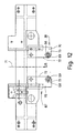
- the opening device 67 consists of two rollers 69 which can be freely rotated about a vertical axis of rotation 68 and in each case a support bracket 70 holding each roller 69. 11 to 13).
- rollers 69 are arranged on a corner region of each support bracket 70 facing away from the production station 22 in the conveying direction 25 in such a way that they protrude from the mutually facing longitudinal edges 72 which run parallel to the longitudinal axis 71 of the conveying path 20 (FIGS. 11 and 12).
- the clear distance between the opposing rollers 69 is dimensioned such that the bearing blocks 56 or the bearing block 63 of the unlockable coupling claw 35 can be moved freely between them, but protruding (lower) outer corner sections 73 of the pawls 60 (opposite) the bearing blocks 56 and 63 Fig.
- a spring element namely a compression spring 77, is arranged below the pivot axes 61 between the pawls 60 (FIG. 10). This pushes the lower ends of the opposing pawls 60 apart, so that the upper free ends 64 thereof move towards one another without touching one another. In this position of the pawls 60 (FIG. 10), an automatic running out of the driver pin 46 of a corresponding workpiece carrier 23 from the coupling body 54 of the unlockable coupling claw 35 is prevented.
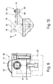
- the opening device 67 in the embodiment of the device shown follows a backstop 74.
- This is also firmly connected to the support frame of the conveyor section 20, that is to say the friction roller conveyor, and has a pawl 75 which can be pivoted in a vertical plane (FIG. 13).
- the pawl 75 is inclined in the conveying direction 25, so that the workpiece carriers 23 can move freely in the conveying direction 25, but are prevented from running back against the conveying direction 25.
- an upper nose 76 of the pawl 75 which cannot be pivoted out of the conveying plane 30 against the conveying direction, comes to rest against a rear edge of the workpiece carrier 23 (FIG. 13).
- a lifting device 78 is assigned to each production station 22. Accordingly, three lifting devices 78 are present in the device shown. The distance between the lifting devices 78 corresponds to the distance of the production station 22 in the production area 21.
- the lifting devices 78 enable the workpiece carriers 23 with workpieces attached to them to be moved out of the conveyor plane 30, namely are lifted off the conveyor section 20 (FIG. 1). At the same time, the workpiece carriers 23 are lifted 78 exactly in front of the respective manufacturing station 22 indexed.
- Each lifting device 78 is formed by a rigid supporting frame 79 which can be moved up and down on a vertical lifting axis 80 transversely to the conveying direction. During this movement, the support frame 79 is guided in the vertical direction by guide columns 81 arranged on its underside, which are mounted essentially without play and can only be moved up and down in guide sleeves 82 (FIG. 3) which are fixedly connected to the support frame of the friction roller conveyor forming the conveying path.
- four vertically towering support columns 83 are arranged on the upper side of the support frame 79. These enter with a free end area into correspondingly formed recesses on the underside of the respective workpiece carriers 23 with the lifting device 78 raised, as a result of which the workpiece carriers 23 are precisely aligned, i.e. indexed, with respect to the respective production station 22 on the one hand, and exactly in the state lifted from the conveyor plane 30 on the other be held in a plane parallel to the conveying plane 30.
- the lifting devices 78 can be raised and lowered at the same time by a corresponding lifting element.
- the lifting member 84 is formed by a (straight) control cam 85 arranged approximately centrally under each support frame 79. All (three) control cams 85 are arranged one behind the other in the conveying direction at a distance below the conveying plane 30 of the conveying section 20 and by one below the longitudinal axis 71 of the conveying section 20 Control rod 86 which can be moved back and forth in the conveying direction 25 (FIG. 1 and 3). Similar to the push rod 29 of the additional conveyor 24, the control rod 86 is discontinuously driven by a further drive unit 87 via a rack and pinion drive.
- each control cam 85 On the profiled top 88 of each control cam 85, a feeler wheel 89 is supported below the support frame 79 of each lifting device 78 (FIG. 3). When the control cam 85 is moved back and forth, this feeler wheel 89 traverses the profile thereof, that is to say the upper side 88, the respective support frame with the workpiece carrier 23 indexed thereon and the workpiece clamped thereon being raised or lowered accordingly.
- the profile of the control curve 85 is formed from essentially four sub-areas, namely (in succession in the direction of conveyance 25) a horizontal lift-holding area 90 which defines the maximum raised position of the workpiece carriers 23, an obliquely directed lifting or lowering area 91, an essentially horizontal one Approach area 92 and a rest area 93, which in turn defines the lowest point of the control curve 85 and is approximately horizontal.
- the latter determines the most lowered position of the lifting device 78, in which the tips of the support columns 83 fastened on the support frame 79 lie below the conveying plane 30 of the conveying path 20. thus enable the workpiece carriers 23 to move freely over the lifting devices 78.
- the profiles of all control cams 85 are of identical design.
- the lifting devices 78 can be raised and lowered synchronously to the same extent.
- the control cams 85 it is conceivable for the control cams 85 to be provided with different profiles in order to adapt to production stations 22 having different machining heights. It is also possible, if necessary, to provide the control cams 85 with a distance from one another which differs from that of the production station 22. As a result, the lifting elements 84 with the workpiece carriers can, if necessary 23 can be raised one after the other.
- the method according to the invention proceeds as follows: Workpiece carriers 23 with workpieces fastened thereon are conveyed on the conveyor line 20, possibly coming from a previous production area, in front of the production area 21.
- a friction roller conveyor forming the conveyor section 20 serves this purpose.
- a workpiece carrier 23 facing the production area 21 in the conveying direction 25 thus enters the inlet section 26, where it is automatically coupled to the unlockable coupling claw 34 located in the inlet point 37.
- the three lifting devices 78 lower the workpiece carriers 23 resting on them so far during assembly that the workpiece carriers 23 rest on the conveying path 20 and the lifting devices 78 are immersed so far under the workpiece carriers 23 that the tips of their support columns 83 lie below the conveyor level 30.
- the workpiece carriers 23 are thereby freely movable on the conveyor path 20.
- the lowering of the lifting devices 78 takes place in that all three control cams 85 connected by the control rod 86 are displaced counter to the conveying direction 25 by the drive unit 87, until the feeler wheels 89 under the supporting frames 79 of the lifting devices 78 are in the respective rest areas 93 of the control curves 85 are located.
- a new workpiece carrier 23 arrives from the inlet section 26 to the first production station 22.
- the workpiece carriers 23 are moved further by the first and second production stations by one production station 22, namely to the second or third production station 22.
- the workpiece carrier 23 located in the last production station 23 (seen in the conveying direction 25) is moved out of the production area 21 into the extension path 27, the pawls 60 of the (rear) unlockable coupling claw 35 being opened at the same time by the opening device 67 for further transport of the corresponding one Workpiece carrier 23 through the friction roller conveyor - for example to the next production area 21.
- this workpiece carrier 23 is moved through the conveyor track 20 at a lower speed than by the additional conveyor 24 in front of and in the production area eich 21 is done.
- the workpiece carriers 23 newly assigned to the respective production stations 22 are then simultaneously lifted from the conveyor path 20 again by the lifting devices 78, namely a linear movement of the control cams 85 in the conveying direction 25 in the conveying direction 25, to a level above the conveying plane 30 for carrying out the corresponding Assembly processes at the manufacturing stations 22.
- the lifting devices 78 that is to say approximately during the assembly processes at the production stations 22, the additional conveyor 24 with the coupling claws 34..36 now attached to the workpiece carriers 23 is decoupled, again by the distance of two Manufacturing stations 22 in the starting position.
- a new workpiece carrier 23 coming from the conveyor section 20 with a corresponding workpiece can be coupled automatically to the unlockable coupling claw 34 located in front of the production area 21.
- the additional conveyor 24 is in its central position opposite the starting position, that is to say it has advanced completely in the conveying direction 25, as a result of which the opening device 67 keeps the pawls 60 of the (rear) unlockable coupling claw 35 permanently open.
- the workpiece carriers 23 can also pass through the unlockable coupling claw 35 unhindered.
Landscapes
- Engineering & Computer Science (AREA)
- Mechanical Engineering (AREA)
- Manufacturing & Machinery (AREA)
- Chemical & Material Sciences (AREA)
- Combustion & Propulsion (AREA)
- Transportation (AREA)
- Automatic Assembly (AREA)
Abstract
Description
Die Erfindung betrifft ein Verfahren zum Transport von Gegenständen, insbesondere von auf Werkstückträgern angeordneten Werkstücken, entlang einer mindestens einen Fertigungsbereich aufweisenden Fertigungsstraße sowie eine Vorrichtung gemäß dem Oberbegriff des Anspruchs 9.The invention relates to a method for transporting objects, in particular workpieces arranged on workpiece carriers, along a production line having at least one production area, and a device according to the preamble of claim 9.
Fertigungsstraßen dienen zur Verkettung mehrerer Fertigungsvorgänge. Dazu ist in die Fertigungsstraße mindestens ein Fertigungsbereich integriert, der wiederum vorzugsweise mehrere Fertigungsstationen umfaßt. Die Fertigungsstationen können sowohl zur Bearbeitung als auch zur Montage, Prüfung oder dergleichen von beliebigen Gegenständen dienen. Demzufolge finden an der Fertigungsstraße eine Vielzahl aufeinanderfolgender Bearbeitungs-, Montage- oder Prüfvorgänge bzw. Kombinationen derselben statt.Production lines serve to chain several production processes. For this purpose, at least one production area is integrated into the production line, which in turn preferably comprises several production stations. The production stations can be used for processing as well as for assembly, testing or the like of any objects. As a result, there are a large number of successive ones on the production line Processing, assembly or testing processes or combinations thereof.
Auf der Fertigungsstraße werden die zu fertigenden, also zu bearbeitenden, zu montierenden, zu prüfenden oder in sonstiger Weise zu behandelnden Gegenstände durch die Fertigungsstationen einer oder mehrerer Fertigungsbereiche hindurchgefördert. Bei diesen zu fördernden Gegenständen handelt es sich üblicherweise um auf Werkstückträgern (Paletten) angeordnete Werkstücke. Es ist aber auch denkbar, die Werkstücke oder dergleichen unmittelbar, also ohne Werkstückträger, auf der Fertigungsstraße entlangzubewegen. Üblicherweise werden derartige Fertigungsstraßen eingesetzt im Automobilbau, nämlich zur Bearbeitung oder Prüfung von auf Werkstückträgern angeordneten Motoren- oder Getriebeteilen bzw. zur Montage derselben.On the production line, the objects to be manufactured, that is to be processed, assembled, tested or otherwise treated, are conveyed through the production stations of one or more production areas. These objects to be conveyed are usually workpieces arranged on workpiece carriers (pallets). However, it is also conceivable to move the workpieces or the like directly along the production line, that is to say without a workpiece carrier. Such production lines are usually used in automobile construction, namely for machining or testing engine or transmission parts arranged on workpiece carriers or for assembling the same.
Bekannt ist es, die Gegenstände, insbesondere auf Werkstückträgern angeordnete Werkstücke, mittels einer Friktionsrollenbahn auf der gesamten Fertigungsstraße entlangzubewegen. Dadurch erfolgt der Weitertransport der Gegenstände von Fertigungsstation zu Fertigungsstation in dem jeweiligen Fertigungsbereich mit der gleichen Geschwindigkeit als von einem Fertigungsbereich zum anderen. Diese längs der gesamten Fertigungsstraße gleiche Transportgeschwindigkeit der Gegenstände hat zur Folge, daß diese im Fertigungsbereich bzw. in den Fertigungsbereichen sich nicht mit einer auf die Bedürfnisse der Fertigung abgestimmte Geschwindigkeit weitertransportieren lassen.It is known to move the objects, in particular workpieces arranged on workpiece carriers, along the entire production line by means of a friction roller conveyor. As a result, the articles are further transported from production station to production station in the respective production area at the same speed as from one production area to another. This same transport speed of the objects along the entire production line has the consequence that they cannot be transported further in the production area or in the production areas at a speed which is matched to the needs of production.
Hiervon ausgehend liegt der Erfindung die Aufgabe zugrunde, ein Verfahren und eine Vorrichtung der eingangs genannten Art zu schaffen, womit ein den Bedürfnissen entsprechender, insbesondere wirtschaftlicher, Weitertransport der Gegenstände durch vorzugsweise mehrere Fertigungsbereiche gewährleistet ist.Proceeding from this, the object of the invention is to create a method and a device of the type mentioned at the outset, which ensures that the objects are transported further, preferably in a more economical manner, through preferably several production areas.
Ein Verfahren zur Lösung dieser Aufgabe weist die Merkmale des Anspruchs 1 auf. Dadurch, daß mindestens durch den Fertigungsbereich bzw. die Fertigungsbereiche hindurch die Gegenstände mit einer anderen Geschwindigkeit weitertransportiert werden als auf den übrigen Abschnitten der Fertigungsstraße, insbesondere zwischen benachbarten Fertigungsbereichen, kann in den Bereichen der Fertigungsstationen ein an die spezifischen Eigenschaften derselben angepaßter Weitertransport der Gegenstände erfolgen.A method for solving this problem has the features of claim 1. Characterized in that the objects are transported at a different speed than at least through the manufacturing area or the manufacturing areas than on the remaining sections of the production line, in particular between adjacent manufacturing areas, in the areas of the manufacturing stations, a further transportation of the items adapted to the specific properties thereof can take place .
Zweckmäßigerweise ist die Weitertransportgeschwindigkeit der Gegenstände mindestens durch einen oder auch mehrere Fertigungsbereiche hindurch größer als auf den übrigen Abschnitten der Fertigungsstraße. Dadurch wird die Zeit, die notwendig ist, um die Gegenstände von der einen Fertigungsstation zur anderen Fertigungsstation zu bringen verringert. Das erfindungsgemäße Verfahren verkürzt somit die Gesamtfertigungszeit. Außerdem kommt es zur besseren Auslastung der Fertigungsstationen, was eine wirtschaftliche Massenfertigung zur Folge hat.The further transport speed of the objects is expediently greater at least through one or more production areas than on the remaining sections of the production line. This reduces the time it takes to move the items from one manufacturing station to another. The method according to the invention thus shortens the overall production time. In addition, there is better utilization of the production stations, which results in economical mass production.
Jedoch ist es auch denkbar, die Gegenstände von Fertigungsstation zu Fertigungsstation mit geringerer Geschwindigkeit als in den übrigen Bereichen der Fertigungsstraße weiterzutransportieren. Dieses kann z. B. dann sinnvoll sein, wenn die Nebenzeit benötigt wird um Umrüstarbeiten (einen Werkzeugwechsel) an den Fertigungsstationen vorzunehmen.However, it is also conceivable to transport the objects from production station to production station at a lower speed than in the other areas of the production line. This can e.g. It can be useful, for example, if the idle time is required to carry out retrofitting work (a tool change) at the production stations.
Bei einem bevorzugten Verfahren erfolgt der Transport der Gegenstände in den jeweiligen Fertigungsbereich hinein, innerhalb desselben, also von Fertigungsstation zu Fertigungsstation und aus dem Fertigungsbereich heraus mit einer größeren Geschwindigkeit als auf den restlichen Abschnitten der Fertigungsstraße, nämlich insbesondere zwischen benachbarten Fertigungsbereichen. Auf diese Weise wird verhindert, daß sich im Fertigungsbereich bzw. in den Fertigungsbereichen aufgrund der unterschiedlichen Transportgeschwindigkeiten der Gegenstände kein Stau mehrerer zu bearbeitender oder zu montierender Gegenstände bildet oder zumindest die Staustrecke verringert wird.In a preferred method, the objects are transported into the respective production area, within the same, ie from the production station to the production station and out of the production area, at a greater speed than on the remaining sections of the production line, namely in particular between adjacent production areas. In this way it is prevented that in the manufacturing area or in the manufacturing areas, due to the different transport speeds of the objects, no jam of several to be processed or forms objects to be assembled or at least the storage distance is reduced.
Gemäß einer vorteilhaften Weiterbildung des Verfahrens werden alle Gegenstände innerhalb des jeweiligen Fertigungsbereichs, in denselben hinein und heraus gleichzeitig mit gleicher (größerer) Geschwindigkeit transportiert, also synchron bewegt. Dadurch sind zum einen Kollisionen benachbarter Gegenstände im jeweiligen Fertigungsbereich ausgeschlossen, während zum anderen sich die Gegenstände mit einem gemeinsamen Förderorgan weiterbewegen lassen.According to an advantageous development of the method, all objects within the respective production area are transported into and out of the same at the same (greater) speed, that is to say moved synchronously. As a result, collisions of adjacent objects in the respective production area are ruled out, while on the other hand the objects can be moved on with a common conveyor.
Weiterhin sieht das erfindungsgemäße Verfahren vor, daß die Gegenstände längs der Fertigungsstraße auf einer durchgehenden Förderstrecke bewegt werden. Auf dieser Förderstrecke werden die Gegenstände von einem Fertigungsbereich zum anderen mit einer (niedrigen) Geschwindigkeit transportiert, wobei durch die Fertigungsbereiche hindurch die Gegenstände zwar auf der Förderstrecke weiterbewegt werden, aber mit einer höheren Geschwindigkeit, indem die Gegenstände von der Förderstrecke entkoppelt werden. Diese Entkopplung geschieht erfindungsgemäß nur bezüglich der Fördergeschwindigkeit, hingegen nicht hinsichtlich der Führung der Gegenstände auf der Förderstrecke. Die Gegenstände bleiben also auch während des Transports mit höherer Geschwindigkeit auf der Förderstrecke.Furthermore, the method according to the invention provides that the objects are moved along the production line on a continuous conveyor line. On this conveyor line, the objects are transported from one production area to another at a (low) speed, the objects being moved further along the conveyor line through the production areas, but at a higher speed by decoupling the objects from the conveyor line. According to the invention, this decoupling occurs only with regard to the conveying speed, but not with regard to the guidance of the objects on the conveying path. The objects therefore remain on the conveyor line at high speed even during transport.
Schließlich ist verfahrensmäßig vorgesehen, daß der gemeinsame (synchrone) Weitertransport der zum jeweiligen Fertigungsbereich gehörenden Gegenstände durch einen diskontinuierlich hin- und herbewegbaren Zusatzförderer vorgenommen wird. Dieser Zusatzförderer führt nach dem Weiterfördern der Gegenstände in Fertigungsrichtung einen leeren (Rück-)Hub aus, der nach einem weiteren wesentlichen Verfahrensmerkmal ohne Mitnahme der Gegenstände unter denselben hindurch erfolgt. Dieses geschieht zweckmäßigerweise nach einem Abheben der Gegenstände von der Förderstrecke. Dadurch geraten die Gegenstände einerseits außer Kontakt mit dem Zusatzförderer, so daß dieser ohne Mitnahme der Gegenstände den (Rück-)Hub ausführen kann, während andererseits durch das Abheben der Gegenstände von der Förderstrecke eine Indexierung der Gegenstände im Bereich der jeweiligen Fertigungsstation erfolgt.Finally, the method provides that the joint (synchronous) further transport of the objects belonging to the respective production area is carried out by means of an additional conveyor which can be moved back and forth discontinuously. After the objects have been conveyed further in the production direction, this additional conveyor carries out an empty (return) stroke which, according to a further essential process feature, takes place underneath them without entrainment. This is expediently done after the objects have been lifted off the conveyor line. As a result, the objects get out of contact on the one hand with the additional conveyor so that it can carry out the (return) stroke without taking the objects with it, while on the other hand the objects are indexed in the area of the respective production station by lifting the objects off the conveyor line.
Eine Vorrichtung zur Lösung der der Erfindung zugrundeliegenden Aufgabe weist die Merkmale des Anspruchs 9 auf. Demnach ist der Förderstrecke mindestens im Fertigungsbereich bzw. in den Fertigungsbereichen und eventuell vor und hinter diesen liegenden Abschnitten der Förderstrecke jeweils ein Zusatzförderer zugeordnet. Diese ermöglichen es, die Gegenstände durch die Fertigungsbereiche hindurch mit einer von der Förderstrecke abweichenden Geschwindigkeit, vorzugsweise einer größeren Geschwindigkeit, weiterzubewegen. Zweckmäßigerweise überlagert der Zusatzförderer die Förderstrecke derart, daß das Tragorgan des Zusatzförderers durch die Förderstrecke gebildet ist, wodurch der Zusatzförderer im wesentlichen nur aus einem antreibbaren Zugmittel gebildet zu werden braucht.A device for achieving the object on which the invention is based has the features of claim 9. Accordingly, an additional conveyor is assigned to the conveyor line at least in the production area or in the production areas and possibly in front of and behind these sections of the conveyor line. These make it possible to move the objects further through the production areas at a speed that deviates from the conveying path, preferably at a higher speed. The additional conveyor expediently overlaps the conveyor line in such a way that the supporting element of the additional conveyor is formed by the conveyor line, as a result of which the additional conveyor essentially only has to be formed from a drivable pulling means.
Gemäß einem weiteren Vorschlag der Erfindung ist der Zusatzförderer als diskontinuierlich arbeitender Förderer ausgebildet, indem er vorzugsweise über ein in Förderrichtung hin- und herbewegbares Zugorgan verfügt. Ein derartiges Zugorgan ermöglicht relativ hohe Fördergeschwindigkeiten mit geringen Beschleunigungswegen. Auch ist ein Antrieb eines derart hin- und herbewegbaren Zugorgans mit einfachen Mitteln möglich. Gleichwohl ist es auch denkbar, den Zusatzförderer mit einem diskontinuierlich angetriebenen umlaufenden Zugorgan zu versehen.According to a further proposal of the invention, the additional conveyor is designed as a discontinuously operating conveyor in that it preferably has a pulling element which can be moved back and forth in the conveying direction. Such a traction element enables relatively high conveying speeds with short acceleration paths. It is also possible to drive a pulling element which can be moved back and forth in this way using simple means. Nevertheless, it is also conceivable to provide the additional conveyor with a discontinuously driven rotating traction element.
Gemäß einer Weiterbildung der mit dem hin- und herbewegbaren Zusatzförderer versehenen Vorrichtung sind beim Vorwärtshub (in Fertigungsrichtung) des Zugorgans die Gegenstände an dieses ankuppelbar und demgegenüber beim Rückwärtshub außer Eingriff zu den Gegenständen bringbar. Zweckmäßigerweise ist dazu der Zusatzförderer mit Kupplungsorganen versehen, die bei auf der Förderstrecke ruhenden Gegenständen an diese ankuppelbar sind. Weiterhin sind die Kupplungsorgane derart ausgebildet, daß ein Kupplungsorgan oder gegebenenfalls auch alle Kupplungsorgane des Zusatzförderers von den zu transportierenden Gegenständen abgekuppelt werden können. Dadurch ist es möglich, die Gegenstände bei Bedarf mit der Transportgeschwindigkeit der Förderstrecke durch eine oder mehrere Fertigungsbereiche an den Fertigungsstationen vorbeizubewegen, wenn in diesen keine Bearbeitung, Montage oder Prüfung der Gegenstände erfolgen soll.According to a development of the device provided with the reciprocable additional conveyor, the objects can be coupled to the latter during the forward stroke (in the direction of manufacture) and, in contrast, can be disengaged from the objects during the reverse stroke. The additional conveyor with coupling elements is expedient for this purpose provided that can be coupled to objects resting on the conveyor line to this. Furthermore, the coupling members are designed in such a way that a coupling member or possibly also all coupling members of the additional conveyor can be uncoupled from the objects to be transported. This makes it possible to move the objects past the production stations at the transport speed of the conveyor line through one or more production areas, if the objects are not to be processed, assembled or checked.
Nach einem weiteren Vorschlag der Erfindung ist dem Fertigungsbereich bzw. den Fertigungsbereichen mindestens eine Hubeinrichtung für die Gegenstände zugeordnet. Zweckmäßigerweise ist die Hubeinrichtung so ausgebildet, daß sie alle in einem Fertigungsbereich befindlichen Gegenstände gleichzeitig von der Förderstrecke anhebt. Durch das Anheben der Gegenstände durch das Huborgan erfolgt einerseits eine Indexierung derselben und andererseits ein Entkoppeln von der Förderstrecke zum Zurückbewegen des Zwischenförderers ohne Mitnahme der (hochbewegten) Gegenstände.According to a further proposal of the invention, at least one lifting device for the objects is assigned to the manufacturing area or areas. The lifting device is expediently designed in such a way that it lifts all objects located in a production area from the conveyor line at the same time. By lifting the objects by means of the lifting element, the same is indexed on the one hand and, on the other hand, decoupled from the conveyor line for moving the intermediate conveyor back without taking the (highly moved) objects.
Weitere Unteransprüche beziehen sich auf vorteilhafte konstruktive Ausbildungen der Kupplungsorgane des Zwischenförderers.Further subclaims relate to advantageous structural designs of the coupling members of the intermediate conveyor.
Das der Erfindung zugrundeliegende Verfahren wird nachfolgend zusammen mit einem bevorzugten Ausführungsbeispiel der Vorrichtung anhand der Zeichnung näher erläutert. In dieser zeigen:
- Fig. 1
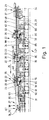
- eine Seitenansicht eines Teils einer Fertigungsstraße in einem Fertigungsbereich,
- Fig. 2
- eine Draufsicht auf den Abschnitt der Fertigungsstraße gemäß der Fig. 1,
- Fig. 3
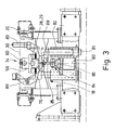
- einen vergrößert dargestellten Querschnitt III-III durch die Fertigungsstraße der Fig. 1 und 2,
- Fig. 4
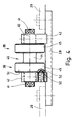
- eine vergrößert dargestellte Seitenansicht analog zur Fig. 1 im Bereich einer den einzelnen Arbeitsstationen zugeordneten Kupplungsklaue,
- Fig. 5
- eine Draufsicht auf die Kupplungsklaue gemäß der Fig. 4,
- Fig. 6
- eine Vorderansicht der Kupplungsklaue gemäß der Fig. 4 und 5,
- Fig. 7
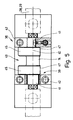
- eine vergrößert dargestellte Seitenansicht gemäß der Fig. 1 im Bereich einer entriegelbaren Kupplungsklaue am Einlauf in einen Fertigungsbereich,
- Fig. 8
- eine Draufsicht auf die entriegelbare Kupplungsklaue gemäß der Fig. 7,
- Fig. 9
- eine Vorderansicht der entriegelbaren Kupplungsklaue gemäß der Fig. 7 und 8,
- Fig. 10
- einen Schnitt X-X durch die entriegelbare Kupplungsklaue der Fig. 8,
- Fig. 11
- einen vertikalen Querschnitt durch die Förderstrecke im Bereich einer Öffnungseinrichtung,
- Fig. 12
- eine Draufsicht auf die Förderstrecke im Bereich der Öffnungseinrichtung gemäß der Fig. 11, und
- Fig. 13
- eine Seitenansicht der Öffnungseinrichtung gemäß der Fig. 11 und 12.
- Fig. 1
- a side view of part of a production line in a manufacturing area,
- Fig. 2
- 2 shows a plan view of the section of the production line according to FIG. 1,
- Fig. 3
- 2 shows an enlarged cross section III-III through the production line of FIGS. 1 and 2,
- Fig. 4
- 2 shows an enlarged side view analogous to FIG. 1 in the area of a coupling claw assigned to the individual work stations,
- Fig. 5
- 4 shows a top view of the coupling claw according to FIG. 4,
- Fig. 6
- 3 shows a front view of the coupling claw according to FIGS. 4 and 5,
- Fig. 7
- 2 shows an enlarged side view according to FIG. 1 in the area of an unlockable coupling claw at the inlet into a production area,
- Fig. 8
- 7 shows a top view of the unlockable coupling claw according to FIG. 7,
- Fig. 9
- 6 shows a front view of the unlockable coupling claw according to FIGS. 7 and 8,
- Fig. 10
- 8 shows a section XX through the unlockable coupling claw of FIG. 8,
- Fig. 11
- a vertical cross section through the conveyor line in the region of an opening device,
- Fig. 12
- a plan view of the conveyor line in the region of the opening device according to FIG. 11, and
- Fig. 13
- a side view of the opening device according to FIGS. 11 and 12.
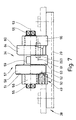
Die gezeigte Vorrichtung dient zur (Teil-)Montage von Motoren oder Getrieben. Hierbei handelt es sich um eine Fertigungsstraße mit einer Förderstrecke 20, die im gezeigten Ausführungsbeispiel durch eine Friktionsrollenbahn bekannter Bauart gebildet ist. An der Förderstrecke 20 sind mit Abstand aufeinanderfolgend mehrere Fertigungsbereiche, also im vorliegenden Falle Montagebereiche, angeordnet, wovon in den Fig. 1 und 2 nur ein Fertigungsbereich 21 dargestellt ist. Jeder Fertigungsbereich 21 verfügt üblicherweise über mehrere Fertigungsstationen, also Montagestationen. Der gezeigte Fertigungsbereich 21 umfaßt drei mit gleichmäßigem Abstand aufeinanderfolgende Fertigungsstationen 22 (in der Fig. 2 andeutungsweise punktstrichliniert dargestellt). Durch die Förderstrecke 20 werden die Fertigungsbereiche 21 einerseits und die Fertigungsstationen 22 andererseits miteinander verbunden, d. h. in produktionstechnischer Hinsicht miteinander verkettet.The device shown is used for the (partial) assembly of motors or gears. This is a production line with a
Bei den auf der Förderstrecke 20 zu den Fertigungsbereichen 21 bzw. Fertigungsstationen 22 zu transportierenden Gegenständen handelt es sich im vorliegenden Falle um auf Werkstückträgern 23 angeordnete Werkstücke, nämlich Motorenblöcke oder Getriebegehäuse mit teilweise montierten Motoren- oder Getriebeteilen, die nicht dargestellt sind. Die Werkstückträger 23 mit den darauf angeordneten Werkstücken werden längs der Förderstrecke 20 von der diese bildenden Friktionsrollenbahn bei ständigem Antrieb derselben weiterbewegt, wobei sich vor den einzelnen Fertigungsstationen 22 gegebenenfalls ein Vorrat aus mehreren auf Werkstückträgern 23 angeordneten Werkstücken sammeln kann, der so lange auf der weiterhin angetriebenen Förderstrecke 20 (Friktionsrollenbahn) stillstehend gepuffert wird, bis die Werkstückträger 23 mit den Werkstücken nach und nach in den jeweiligen Fertigungsbereich 21 eingefördert werden.In the present case, the objects to be transported on the
Erfindungsgemäß ist der Fertigungsstation 22 und gegebenenfalls weiteren nicht dargestellten Fertigungsstationen der Fertigungsstraße ein Zusatzförderer 24 zugeordnet. Der Zusatzförderer 24 verbindet die mit Abstand aufeinanderfolgenden Fertigungsstationen 22 des Fertigungsbereichs 21 und erstreckt sich darüber hinaus über eine in Förderrichtung 25 gesehen vor der ersten Fertigungsstation 22 angeordnete Einlaufstrecke 26 und eine sich an die letzte Fertigungsstation 22 anschließende Ausschubstrecke 27 (Fig. 1 und 2). Der Zusatzförderer 24 verfügt im wesentlichen nur über ein längliches, in Förderrichtung 25 hin- und herbewegbares Zugorgan 28. Als Tragorgan für den Zusatzförderer 24 dient die über den Bereich desselben weiterhin durchgehende Förderstrecke 20, nämlich die Friktionsrollenbahn. Diese übt demnach im Fertigungsbereich 21, der Einlaufstrecke 26 und der Ausschubstrecke 27 nur eine tragende, nicht aber eine antreibende Funktion aus, da diese vom Zugorgan 28 des Zusatzförderers 24 übernommen wird.According to the invention, an
Das Zugorgan 28 besteht im wesentlichen aus einer in Förderrichtung 25 hin- und herbewegbaren Schubstange 29, die abgesehen von der freien Beweglichkeit in und gegen die Förderrichtung 25 ortsfest mittig unterhalb der Förderebene 30 der Förderstrecke 20 angeordnet ist (Fig. 3). In einen Teilbereich ist die Unterseite der Schubstange 29 zahnstangenartig ausgebildet. In diesen zahnstangenartigen Bereich der Schubstange 29 greift ein Ritzel 31 einer an einer Seite neben der Förderstrecke 20 fest angeordneten Antriebseinheit 32 ein. Durch die Antriebseinheit 32, bei der es sich beispielsweise um einen exakt wegsteuerbaren Servoantrieb handeln kann, ist die Schubstange 29 exakt um den Abstand der untereinander gleichmäßig weit voneinander entfernten Fertigungsstation 22 in Förderrichtung 25 unter Mitnahme der Werkstückträger 23 und der darauf angeordneten Werkstücke weiterbewegbar. Der Antrieb der Schubstange 29 erfolgt dabei derart, daß diese sich mit einer größeren Geschwindigkeit in Förderrichtung 25 bewegt als die Werkstückträger 23 mit den Werkstücken von der Friktionsrollenbahn der Förderstrecke 20 außerhalb des Zusatzförderers 24 weiterbewegbar sind. Durch die schnelle Weiterbewegung der Werkstückträger 23 mit den Werkstücken durch den Zusatzförderer 24 werden in den Bereich desselben die Friktionsrollen der Förderstrecke 20 "überholt", also schneller gedreht als dies durch den Antrieb der Friktionsrollenbahn geschieht.The
Zur Mitnahme bzw. zum Weitertransport der Werkstückträger 23 mit den darauf angeordneten Werkstücken im Fertigungsbereich 21, der Einlaufstrecke 26 und der Ausschubstrecke 27 sind die auf der Förderstrecke 20 ruhenden Werkstückträger 23 an die Schubstange 29 ankuppelbar. Die Schubstange 29 verfügt dazu an der Oberseite über mehrere in Abstand voneinander angeordnete Kupplungsorgane. Der Abstand der Kupplungspunkte 33 an den Kupplungsorganen entspricht dem Abstand der Fertigungsstation 22 (Fig. 1 und 2).In order to take the
Die Kupplungsorgane sind erfindungsgemäß unterschiedlich ausgebildet, indem nämlich die in Förderrichtung 25 am Anfang und am Ende des Fertigungsbereichs 21 sich befindenden Kupplungsorgane als entriegelbare Kupplungsklauen 34, 35 ausgebildet sind. Zwischen den entriegelbaren Kupplungsklauen 34, 35 sind als einfache Kupplungsklauen 36 ausgebildete Kupplungsorgane angeordnet. Im gezeigten Ausführungsbeispiel mit drei Fertigungsstationen 22 sind dieses zwei Kupplungsklauen 36. Insgesamt verfügt der hier gezeigte Zusatzförderer 24 demnach über vier Kupplungsorgane (entriegelbare Kupplungsklauen 34, 35 bzw. Kupplungsklauen 36), also ein Kupplungsorgan mehr als Fertigungsstationen 22 im gezeigten Fertigungsbereich 21 vorhanden sind.The coupling members are designed differently according to the invention, namely that the coupling members located in the conveying
Die in Förderrichtung am Anfang des Fertigungsbereichs 21 liegende entriegelbare Kupplungsklaue 34 ist durch die Schubstange 29 zwischen dem Einlaufpunkt 37 der Einlaufstrecke 26 und die in bezug auf die Förderrichtung 25 erste Fertigungsstation 22 hin- und herbewegbar. Die auf der entriegelbaren Kupplungsklaue 34 folgende Kupplungsklaue 36 ist zwischen der ersten und zweiten Fertigungsstation 22 und die zweite Kupplungsklaue 36 zwischen der zweiten und dritten Fertigungsstation 22 hin- und herbewegbar. Schließlich ist die hintere entriegelbare Kupplungsklaue 35 zwischen der dritten Fertigungsstation 22 und dem Auslaufpunkt 38 der Ausschubstrecke 27 verfahrbar.The
Die Kupplungsklauen 36 verfügen über einen rotationssymmetrischen Kupplungskörper 39, der um eine parallel oberhalb der Schubstange 29 liegende, in Förderrichtung 25 verlaufende Drehachse 40 drehbar ist. Dazu ist der Kupplungskörper 39 mit zwei außenliegenden Lagerzapfen 41 in zwei mit Abstand voneinander gegenüber der Schubstange 29 nach oben vorstehenden Lagerböcken 42 gelagert (Fig. 4 bis 6). Verbunden sind die Lagerzapfen 41 durch ein Kupplungsmittelteil 43, das über einen zylindrischen Mittenabschnitt 44 und zwei diesen nach außen hin begrenzende, gleich ausgebildete Kragenabschnitte 45 verfügt. Dadurch verfügt das Kupplungsmittelteil 43 (quer zur Förderrichtung 25 gesehen) über einen H-förmigen Querschnitt. Von oben her greift zwischen die durch den Mittenabschnitt 44 voneinander beabstandeten Kragenabschnitte 45 ein unter jedem Werkstückträger 23 angeordneter Mitnehmerzapfen 46 in das Kupplungsmittelteil 43 ein zur reibschlüssigen Ankupplung des jeweiligen Werkstückträgers 23 an den Zusatzförderer 24 (Fig. 1).The
An einer Seite fehlt jedem Kragenabschnitt 45 ein Kreisabschnitt, der bis etwa an den Mittenabschnitt 44 des Kupplungskörpers 39 heranreicht (Fig. 5). Durch entsprechendes Verdrehen des Kupplungskörpers 39 um seine Drehachse 40 können die etwa mit dem Mittenabschnitt 44 bündig abschließenden ebenen Abschnittsflächen 47 der Kragenabschnitte 45 zur Förderebene 30 derart ausgerichtet werden, daß die Abschnittsflächen 47 und der Mittenabschnitt 44 so weit unterhalb der Förderebene 30 liegen, daß die Mitnehmerzapfen 46 unterhalb der Werkstückträger 23 nicht mehr in eine formschlüssige Verbindung mit der Kupplungsklaue 36 bringbar sind und dadurch keine Ankupplung der Werkstückträger 23 an den Zusatzförderer 24 möglich ist. Um alle Kupplungsorgane in eine eine Ankupplung an die Werkstückträger 23 nicht zulassende Stellung zu bringen, sind ihre Kupplungskörper 39 an zueinandergerichteten freien Enden der Lagerzapfen 41 miteinander verbunden durch auf den Drehachsen 40 liegende Schaltwellen 48 (Fig. 1 und 5).On one side, each
Zur Arretierung der Kupplungskörper 39 in einer eine Verbindung zu den Werkstückträger 23 ermöglichenden Stellung (gemäß der Fig. 4 bis 6) einerseits und einer frei geschalteten Stellung andererseits ist im gezeigten Ausführungsbeispiel einem Lagerbock 42 ein Arretierungsorgan 49 zugeordnet, das eine federbelastete Kugel 50 aufweist, die gegen die zum Lagerbock 42 gerichtete Stirnseite 51 eines entsprechenden Kragenabschnitts 45 drückt und hier formschlüssig in den entsprechenden Arretierungspositionen zugeordneten Vertiefungen 52 in der Stirnseite 51 des Kragenabschnitts 45 eingreift (Fig. 4).To lock the
Die entriegelbaren Kupplungsklauen 34 verfügen ebenfalls über einen um eine Drehachse 53 verdrehbaren Kupplungskörper 54. Auch dieser ist mit zwei gegenüberliegenden Lagerzapfen 55 drehbar in zwei mit Abstand voneinander auf der Schubstange 29 angeordneten Lagerböcken 56 gelagert. Insofern entsprechen die entriegelbaren Kupplungsklauen 34, 35 der vorstehend beschriebenen Kupplungsklaue 36. Abweichend hiervon ist jedoch das Kupplungsmittelteil 57 ausgebildet, das nämlich nur über einen Kragenabschnitt 58 und einen im Durchmesser kleineren Mittenabschnitt 59 verfügt. An der dem Kragenabschnitt 58 gegenüberliegenden Seite ist der Mittenabschnitt 59 begrenzt durch zwei schwenkbare Sperrklinken 60 (Fig. 7 bis 9). Die beiden länglichen Sperrklinken 60 sind an gegenüberliegenden Seiten des bis zum entsprechenden Lagerzapfen 41 durchgehenden Mittenabschnitts 59 gelagert, und zwar um unterhalb der Drehachse 53 liegenden Schwenkachse 61. Diese ist gebildet durch jeweils einen Zylinderstift 62, der an einem Ende im entsprechenden Lagerbock 56 und am anderen Ende einen seitlich neben dem Mittenabschnitt 59 angeordneten halbhohen Lagerbock 63 gehalten ist. Mit oberen freien Enden 64 ragen die beiden Sperrklinken 60 gegenüber dem Mittenabschnitt 59 des Kupplungskörpers 54 hervor, so daß (quer zur Förderrichtung 25) gesehen der Kupplungskörper 54 durch seinen einen Kragenabschnitt 58, den Mittenabschnitt 59 und die Sperrklinken 60 ein U-förmiges Profil erhält zur formschlüssigen Aufnahme eines entsprechenden Mitnehmerzapfens 46 eines Werkstückträgers 23 zwischen dem Kragenabschnitt 58 einerseits und den beiden Sperrklinken 60 des Kupplungskörpers 54 andererseits (Fig. 1).The
Bei der hier gezeigten entriegelbaren Kupplungsklaue 34 (Fig. 7 bis 9) liegen die Sperrklinken 60 in bezug auf die Förderrichtung 25 vor dem Kragenabschnitt 58. Zum Einlaufen des Mitnehmerzapfens 46 eines an die entriegelbare Kupplungsklaue 34 anzukuppelnden Werkstückträgers 23 in den Bereich des Mittenabschnitts 59 des Kupplungsmittelteils 57 sind die freien Enden 64 beider Sperrklinken 60 mit Anschrägungen 65 versehen. Diese bilden ein in Förderrichtung 25 sich verjüngendes "V" zwischen den freien Enden 64 der Sperrklinken 60 zum selbsttätigen Auseinanderschwenken derselben um ihre Schwenkachsen 61 durch den Mitnehmerzapfen 46 eines einlaufenden Werkstückträgers 23. Auf diese Weise ist eine selbsttätige Ankupplung des jeweiligen Werkstückträgers 23 an eine unbesetzte entriegelbare Kupplungsklaue 34 im Bereich der Einlaufstrecke 26 vor der ersten Fertigungsstation 22 möglich (Fig. 8).In the
Der einzige Kragenabschnitt 58 des Kupplungskörpers 54 ist wiederum mit einem Kreissegmentabschnitt versehen, verfügt also wie die Kragenabschnitte 45 der Kupplungsklauen 36 über eine Abschnittsfläche 47, die durch ein entsprechendes Verdrehen des Kupplungskörpers 54 und seine Drehachse 53 in eine Ebene unterhalb der Förderebene 30 bringbar ist zum freien Durchlauf der nicht durch den Zusatzförderer 24 weiterzufördernden Werkstückträger 23 an den Kragenabschnitt 58 der entriegelbaren Kupplungsklaue 34 vorbei. Dabei werden wie beim Eintreten des Mitnehmerzapfens 46 eines entsprechenden Werkstückträgers 23 zum Ankuppeln an die entriegelbare Kupplungsklaue 34 die Sperrklinken 60 selbsttätig auseinanderbewegt. Zum "Freischalten" der entriegelbaren Kupplungsklaue 34 mit den übrigen Kupplungsklauen 36 ist die entriegelbare Kupplungsklaue 34 durch eine weitere Schaltwelle 48 mit der in Förderrichtung 25 hierauf folgenden Kupplungsklaue 36 verbunden. Dazu fluchtet die Drehachse 53 der entriegelbaren Kupplungsklaue 34 mit denen der Kupplungsklauen 36. Außerdem sind durch die Schaltwellen 48 die Kupplungsklauen 36 einerseits und die entriegelbare Kupplungsklaue 34 andererseits derart miteinander verbunden, daß die Abschnittsflächen 47 bzw. 66 der Kragenabschnitte 45 und 58 miteinander in einer gemeinsamen Ebene liegen (Fig. 2).The
Die im Bereich zwischen der letzten Fertigungsstation 22 und dem Auslaufpunkt 38 der Ausschubstrecke 27 sich bewegende entriegelbare Kupplungsklaue 35 entspricht im grundsätzlichen Aufbau der vorstehend beschriebenen entriegelbaren Kupplungsklaue 34 vor der Fertigungsstation 22. Allerdings ist die entriegelbare Kupplungsklaue 35 gegenüber der Kupplungsklaue 34 um 180° versetzt der Schubstange 29 zugeordnet. Demnach folgen - in Förderrichtung 25 gesehen - auf den Kupplungskörper 54 die beiden Sperrklinken 60. In der entriegelbaren Kupplungsklaue 35 ist der Mitnehmerzapfen 46 eines den Fertigungsbereich 21 verlassenen Werkstückträgers 23 formschlüssig gehalten. Da die gegenüberliegenden Anschrägungen 65 an den Sperrklinken 60 sich V-förmig zum Mittenabschnitt 59 des Kupplungskörpers 54 verjüngen, können die Sperrklinken 60 vom Mitnehmerzapfen 46 nicht selbsttätig geöffnet werden zum Verlassen eines Werkstückträgers 23 bzw. des daran angeordneten Mitnehmerzapfens 46 der entriegelbaren Kupplungsklaue 35.The
Um die entriegelbare Kupplungsklaue 35 in Förderrichtung 25 öffnen zu können, sind durch eine Öffnungseinrichtung 67 die Sperrklinken 60 gegensinnig verschwenkbar, derart, daß die freien Enden 64 der Sperrklinken 60 sich auseinanderbewegen zum freien Auslauf eines Mitnehmerzapfens 46 des entsprechenden Werkstückträgers 23 aus der entriegelbaren Kupplungsklaue 35. Dazu ist die Öffnungseinrichtung 67 ortsfest an der Förderstrecke 20 hinter dem Fertigungsbereich 21 angeordnet, nämlich mit einem Traggestell der Friktionsrollenbahn verbunden. Die Öffnungseinrichtung 67 besteht aus zwei um eine vertikale Drehachse 68 frei drehbare Rollen 69 und jeweils eine jede Rolle 69 haltende Traglasche 70. Die Rollen 69 sind mit den Traglaschen 70 mit gleichmäßigen Abstand an gegenüberliegenden Seiten einer Längsachse 71 der Förderstrecke 20 am Traggestell fest angeordnet (Fig. 11 bis 13). An einem von der Fertigungsstation 22 in Förderrichtung 25 gesehen weggerichteten Eckbereich jeder Traglasche 70 sind die Rollen 69 derart angeordnet, daß sie gegenüber den einander zugerichteten, parallel zur Längsachse 71 der Förderstrecke 20 verlaufenden Längskanten 72 vorstehen (Fig. 11 und 12). Der lichte Abstand der gegenüberliegenden Rollen 69 ist dabei so bemessen, daß zwischen ihnen die Lagerböcke 56 bzw. der Lagerbock 63 der entriegelbaren Kupplungsklaue 35 frei hindurchbewegbar sind, aber gegenüber den Lagerböcken 56 bzw. 63 vorstehende (untere) äußere Eckabschnitte 73 der Sperrklinken 60 (Fig. 10) Anlage an den Rollen 69 erhalten und beim Vorbeibewegen der entriegelbaren Kupplungsklaue 35 an den Rollen hiervon die äußeren Eckabschnitte 73 in den Bereich der Lagerböcke 56, 63 gedrückt werden zum Verschwenken der Sperrklinken 60 und Öffnen ihrer gegenüberliegenden freien Enden 64. Wenn sich demnach die entriegelbare Kupplungsklaue 35 im Bereich der Öffnungseinrichtung 67 befindet, kann durch die geöffneten Sperrklinken 60 ein Mitnehmerzapfen 46 des entsprechenden Werkstückträgers 23 in Förderrichtung 25 aus der entriegelbaren Kupplungsklaue 35 und somit den Bereich des Zusatzförderers 24 herauslaufen.In order to be able to open the
Zum selbsttätigen Zusammenbewegen der Sperrklinken 60 in ihre Sperrstellungen nach dem Verlassen der Öffnungseinrichtung 67 ist unterhalb der Schwenkachsen 61 zwischen den Sperrklinken 60 ein Federorgan, nämlich eine Druckfeder 77, angeordnet (Fig. 10). Diese drückt die unteren Enden der gegenüberliegenden Sperrklinken 60 auseinander, so daß die oberen freien Enden 64 derselben sich aufeinanderzubewegen, ohne sich jedoch zu berühren. In dieser Position der Sperrklinken 60 (Fig. 10) wird wiederum ein selbsttätiges Herauslaufen des Mitnehmerzapfens 46 eines entsprechenden Werkstückträgers 23 aus dem Kupplungskörper 54 der entriegelbaren Kupplungsklaue 35 verhindert.To automatically move the
In Förderrichtung 25 folgt auf die Öffnungseinrichtung 67 beim gezeigten Ausführungsbeispiel der Vorrichtung eine Rücklaufsperre 74. Diese ist auch fest mit dem Traggestell der Förderstrecke 20, also der Friktionsrollenbahn, verbunden und verfügt über eine in einer vertikalen Ebene schwenkbare Sperrklinke 75 (Fig. 13). Die Sperrklinke 75 ist in Förderrichtung 25 geneigt, so daß über diese die Werkstückträger 23 in Förderrichtung 25 ungehindert hinwegfahren können, aber an einem Zurücklaufen gegen die Förderrichtung 25 gehindert werden. In diesem Falle kommt eine obere Nase 76 der entgegen der Förderrichtung nicht aus der Förderebene 30 herausschwenkbaren Sperrklinke 75 zur Anlage an einer rückwärtigen Kante des Werkstückträgers 23 (Fig. 13).In the conveying
Jeder Fertigungsstation 22 ist eine Hubeinrichtung 78 zugeordnet. Bei der gezeigten Vorrichtung sind demnach drei Hubeinrichtungen 78 vorhanden. Der Abstand der Hubeinrichtungen 78 zueinander entspricht dem Abstand der Fertigungsstation 22 im Fertigungsbereich 21. Durch die Hubeinrichtungen 78 sind die Werkstückträger 23 mit darauf befestigten Werkstücken aus der Förderebene 30 herausbewegbar, werden nämlich von der Förderstrecke 20 abgehoben (Fig. 1). Gleichzeitig werden die Werkstückträger 23 durch die Hubeinrichtung 78 exakt vor der jeweiligen Fertigungsstation 22 indexiert. In dem von der Förderstrecke 20 abgehobenen Zustand der Werkstückträger 23 kommen ihre Mitnehmerzapfen 46 außer Eingriff mit den Kupplungsklauen 34..36 des Zusatzförderers 24, der dadurch ohne eine Mitnahme der Werkstückträger 23 einen (Rück-)Hub gegen die Förderrichtung 25 um den Abstand zweier Fertigungsstationen 22 ausüben kann und dadurch wiederum in seine Ausgangsposition gelangt.A lifting
Gebildet wird jede Hubeinrichtung 78 durch einen starren Tragrahmen 79, der quer zur Förderrichtung auf einer vertikalen Hubachse 80 auf- und abbewegbar ist. Bei dieser Bewegung wird der Tragrahmen 79 in vertikaler Richtung geführt durch an seiner Unterseite angeordnete Führungssäulen 81, die im wesentlichen spielfrei ausschließlich auf- und abbewegbar in fest mit dem Traggestell der die Förderstrecke bildenden Friktionsrollenbahn verbundenen Führungshülsen 82 (Fig. 3) gelagert sind.Each lifting
An der Oberseite des Tragrahmens 79 sind im gezeigten Ausführungsbeispiel vier senkrecht hochragende Tragsäulen 83 angeordnet. Diese treten mit einem freien Endbereich in korrespondierend ausgebildete Ausnehmungen an der Unterseite der jeweiligen Werkstückträger 23 bei angehobener Hubeinrichtung 78 ein, wodurch die Werkstückträger 23 einerseits gegenüber der jeweiligen Fertigungsstation 22 genau ausgerichtet, also indexiert werden, und andererseits im von der Förderebene 30 abgehobenen Zustand exakt in einer zur Förderebene 30 parallelen Ebene gehalten werden.In the exemplary embodiment shown, four vertically towering
Die Hubeinrichtungen 78 sind gleichzeitig durch ein entsprechendes Huborgan heb- und senkbar. Das Huborgan 84 wird gebildet durch eine etwa mittig unter jedem Tragrahmen 79 angeordnete (geradlinige) Steuerkurve 85. Sämtliche (drei) Steuerkurven 85 sind in Förderrichtung mit Abstand hintereinanderliegend unterhalb der Förderebene 30 der Förderstrecke 20 angeordnet und durch eine unterhalb der Längsachse 71 der Förderstrecke 20 in Förderrichtung 25 hin- und herbewegbare Steuerstange 86 miteinander verbunden (Fig. 1 und 3). Die Steuerstange 86 wird ähnlich wie die Schubstange 29 des Zusatzförderers 24 über einen Zahnstangenantrieb von einer weiteren Antriebseinheit 87 diskontinuierlich angetrieben.The
An der profilierten Oberseite 88 jeder Steuerkurve 85 stützt sich ein unterhalb des Tragrahmens 79 jeder Hubeinrichtung 78 angeordnetes Tastrad 89 ab (Fig. 3). Dieses Tastrad 89 fährt beim Hin- und Herbewegen der Steuerkurve 85 das Profil derselben, also die Oberseite 88, ab, wobei der jeweilige Tragrahmen mit dem darauf indexierten Werkstückträger 23 und dem darauf festgespannten Werkstück entsprechend angehoben oder abgesenkt wird. Dazu wird das Profil der Steuerkurve 85 aus im wesentlichen vier Teilbereiche gebildet, nämlich (in Förderrichtung 25 aufeinanderfolgend) einen horizontalen Hubhaltebereich 90, der die maximal hochgefahrene Position der Werkstückträger 23 definiert, einen schräggerichteten Hebe- bzw. Senkbereich 91, einen im wesentlichen horizontal verlaufenden Anfahrbereich 92 und einen die tiefste Stelle der Steuerkurve 85 definierenden, wiederum etwa horizontalen Ruhebereich 93. Letzterer bestimmt die am weitesten abgesenkte Position der Hubeinrichtung 78, bei dem die Spitzen der auf dem Tragrahmen 79 befestigten Tragsäulen 83 unterhalb der Förderebene 30 der Förderstrecke 20 liegen, also ein ungehindertes Hinwegbewegen der Werkstückträger 23 über die Hubeinrichtungen 78 hinweg ermöglichen.On the profiled
Im gezeigten Ausführungsbeispiel sind die Profile sämtlicher Steuerkurven 85 gleich ausgebildet. Dadurch sind die Hubeinrichtungen 78 synchron in gleichem Maße heb- und senkbar. Alternativ ist es denkbar zur Anpassung an unterschiedliche Bearbeitungshöhen aufweisende Fertigungsstationen 22 die Steuerkurven 85 mit unterschiedlichen Profilen zu versehen. Auch ist es gegebenenfalls möglich, die Steuerkurven 85 mit einem Abstand zueinander zu versehen, der von dem der Fertigungsstation 22 abweicht. Dadurch können gegebenenfalls die Huborgane 84 mit den Werkstückträgern 23 beispielsweise nacheinander angehoben werden.In the exemplary embodiment shown, the profiles of all
Mit der vorstehend beschriebenen Vorrichtung läuft das erfindungsgemäße Verfahren wie folgt ab:
Auf der Förderstrecke 20 werden Werkstückträger 23 mit darauf befestigten Werkstücken gegebenenfalls von einem vorhergehenden Fertigungsbereich kommend vor den Fertigungsbereich 21 gefördert. Hierzu dient im gezeigten Ausführungsbeispiel eine die Förderstrecke 20 bildende Friktionsrollenbahn. Ein in Förderrichtung 25 dem Fertigungsbereich 21 zugewandter Werkstückträger 23 gelangt so in die Einlaufstrecke 26, wo er an die sich im Einlaufpunkt 37 befindliche entriegelbare Kupplungsklaue 34 selbsttätig angekuppelt wird.With the device described above, the method according to the invention proceeds as follows:
Wenn die drei Fertigungsstationen 22 ihr Montageprogramm beendet haben, werden durch die drei Hubeinrichtungen 78 die bei der Montage darauf ruhenden Werkstückträger 23 so weit abgesenkt, daß die Werkstückträger 23 auf der Förderstrecke 20 aufliegen und die Hubeinrichtungen 78 so weit unter den Werkstückträgern 23 wegtauchen, daß die Spitzen ihrer Tragsäulen 83 unterhalb der Förderebene 30 liegen. Die Werkstückträger 23 sind dadurch frei bewegbar auf der Förderstrecke 20.When the three
Das Herunterfahren der Hubeinrichtungen 78 geschieht dadurch, daß alle drei durch die Steuerstange 86 verbundenen Steuerkurven 85 entgegen der Förderrichtung 25 durch die Antriebseinheit 87 verschoben werden, und zwar so weit, bis die Tasträder 89 unter den Tragrahmen 79 der Hubeinrichtungen 78 sich in den jeweiligen Ruhebereichen 93 der Steuerkurven 85 befinden.The lowering of the
Durch das Absenken der Werkstückträger 23 auf die Förderstrecke 20 werden automatisch die Mitnehmerzapfen 46 der Werkstückträger 23 in die beiden Kupplungsklauen 36 und die am Ende des Fertigungsbereichs 21 sich befindende entriegelbare Kupplungsklaue 35 eingekuppelt. Danach sind insgesamt vier Werkstückträger 23 über die Kupplungsklauen 34..36 an den Zusatzförderer 24 angekuppelt. Über die Antriebseinheit 32 und die Schubstange 29 werden nun alle Kupplungsklauen 34..36 mit den Werkstückträgern 23 um den Abstand von einer Fertigungsstation 22 zur anderen weitergefahren, und zwar erfindungsgemäß mit einer höheren Geschwindigkeit als auf der Förderstrecke 20, da die Friktionsrollenbahn der Förderstrecke 20 mit einer geringeren Geschwindigkeit angetrieben wird als der Zusatzförderer 24.By lowering the
Durch das Vorfahren des Zusatzförderers 24 in Förderrichtung 25 gelangt ein neuer Werkstückträger 23 aus der Einlaufstrecke 26 zur ersten Fertigungsstation 22. Gleichzeitig werden von der ersten und zweiten Fertigungsstation die Werkstückträger 23 um eine Fertigungsstation 22 weiterbewegt, nämlich zur zweiten bzw. dritten Fertigungsstation 22. Schließlich wird der in der ( in Förderrichtung 25 gesehen) letzten Fertigungsstation 23 sich befindende Werkstückträger 23 aus dem Fertigungsbereich 21 heraus in die Ausschubstrecke 27 bewegt, wobei gleichzeitig durch die Öffnungseinrichtung 67 die Sperrklinken 60 der (hinteren) entriegelbaren Kupplungsklaue 35 geöffnet werden zum Weitertransport des entsprechenden Werkstückträgers 23 durch die Friktionsrollenbahn - beispielsweise zum nächsten Fertigungsbereich 21. Dabei wird dieser Werkstückträger 23 durch die Förderstrecke 20 mit geringerer Geschwindigkeit bewegt als dies durch den Zusatzförderer 24 vor und im Fertigungsbereich 21 erfolgt.By advancing the
Die neu den jeweiligen Fertigungsstationen 22 zugeordneten Werkstückträger 23 werden nun gleichzeitig durch die Hubeinrichtungen 78, nämlich ein in Förderrichtung 25 erfolgendes geradliniges Verfahren der Steuerkurven 85 in Förderrichtung 25, wieder von der Förderstrecke 20 abgehoben auf ein über der Förderebene 30 liegendes Niveau zur Durchführung der entsprechenden Montagevorgänge an den Fertigungsstationen 22. Bei durch die Hubeinrichtungen 78 hochgehobenen Werkstückträgern 23, also etwa während der Montagevorgänge an den Fertigungsstationen 22, erfolgt ein Zurückbewegen des Zusatzförderers 24 mit den daran befestigten nunmehr von den Werkstückträgern 23 entkuppelten Kupplungsklauen 34..36, und zwar wiederum um den Abstand zweier Fertigungsstationen 22 in die Ausgangsstellung. Hierbei ist selbsttätig an die vor dem Fertigungsbereich 21 sich befindende, entriegelbare Kupplungsklaue 34 ein neuer von der Fördersrecke 20 kommender Werkstückträger 23 mit einem entsprechenden Werkstück ankuppelbar.The
Sollte es erforderlich sein, daß die Werkstückträger 23 (mit oder ohne Werkstücke) ohne einen Montagevorgang durch den Fertigungsbereich 21 hindurchzufördern sind, erfolgt eine vorzugsweise 90°-Verdrehung der Schaltwellen 48, wodurch die Kupplungskörper 39 bzw. 54 sämtlicher Kupplungsklauen 34..36 derart verdreht werden, daß die Abschnittsflächen 47, 66 etwa parallel unter der Förderebene 30 liegen, und dadurch ohne den Zusatzförderer 24 die Werkstückträger 23 auf der Friktionsrollenbahn der Förderstrecke 20 mit einer dieser entsprechenden Geschwindigkeit weiterbewegt werden, vorzugsweise durch den gesamten Fertigungsbereich 21 hindurch zum nächsten Fertigungsbereich 21 bzw. zum Ende der Förderstrecke 20. In diesem Falle treten weder der Zusatzförderer 24 noch die Hubeinrichtungen 78 in Aktion. Weiterhin befindet sich bei diesem freien Hindurchfahren der Werkstückträger 23 durch den Fertigungsbereich 21 der Zusatzförderer 24 in seiner der Ausgangsposition gegenüberliegenden Mittelstellung, ist also vollständig in Förderrichtung 25 vorgefahren, wodurch die Öffnungseinrichtung 67 die Sperrklinken 60 der (hinteren) entriegelbaren Kupplungsklaue 35 permanent geöffnet hält. Hierdurch können die Werkstückträger 23 auch die entriegelbare Kupplungsklaue 35 ungehindert durchfahren.Should it be necessary for the workpiece carriers 23 (with or without workpieces) to be conveyed through the production area 21 without an assembly process, there is preferably a 90 ° rotation of the
Claims (19)
Applications Claiming Priority (2)
| Application Number | Priority Date | Filing Date | Title |
|---|---|---|---|
| DE19904002414 DE4002414A1 (en) | 1990-01-27 | 1990-01-27 | METHOD AND DEVICE FOR TRANSPORTING OBJECTS ALONG A PRODUCTION ROAD |
| DE4002414 | 1990-01-27 |
Publications (2)
| Publication Number | Publication Date |
|---|---|
| EP0439680A2 true EP0439680A2 (en) | 1991-08-07 |
| EP0439680A3 EP0439680A3 (en) | 1992-12-02 |
Family
ID=6398913
Family Applications (1)
| Application Number | Title | Priority Date | Filing Date |
|---|---|---|---|
| EP19900118926 Withdrawn EP0439680A3 (en) | 1990-01-27 | 1990-10-04 | Method of and device for transporting items along a production line |
Country Status (2)
| Country | Link |
|---|---|
| EP (1) | EP0439680A3 (en) |
| DE (1) | DE4002414A1 (en) |
Cited By (4)
| Publication number | Priority date | Publication date | Assignee | Title |
|---|---|---|---|---|
| TR26813A (en) * | 1991-08-13 | 1994-08-09 | Fiat Auto Spa | Especially for motor vehicles, a lifting system and conveyor system (conveyor). |
| WO1998034858A1 (en) * | 1997-02-06 | 1998-08-13 | Robert Bosch Gmbh | Transport system |
| EP1059222A3 (en) * | 1999-06-09 | 2003-04-02 | Advanced Technologies S.r.l. | Vehicle body assembly and processing line |
| CN113859902A (en) * | 2021-09-22 | 2021-12-31 | 福耀集团(福建)机械制造有限公司 | Transmission line body, decoration strip buckle transmission system and transmission method |
Families Citing this family (4)
| Publication number | Priority date | Publication date | Assignee | Title |
|---|---|---|---|---|
| DE4209991A1 (en) * | 1992-03-27 | 1993-09-30 | Hermann Horndasch | Transport system for stepped conveyance of workpieces - has movable transport strip and entrainment members set between two parallel supports on which workpieces rest. |
| DE10145238C1 (en) | 2001-09-13 | 2003-04-17 | Foerdersysteme Engineering Gmb | Lift table controlled by a control cam |
| DE10240794A1 (en) | 2002-08-30 | 2004-03-11 | Grob-Werke Burkhart Grob E.K. | Transport device for transporting workpieces |
| CN115055953B (en) * | 2022-07-09 | 2023-09-29 | 杭州新兴车料有限公司 | Manufacturing process of bicycle aluminum alloy shelf with LED tail lamp |
Citations (4)
| Publication number | Priority date | Publication date | Assignee | Title |
|---|---|---|---|---|
| DE3203295A1 (en) * | 1981-01-30 | 1982-08-12 | Honda Giken Kogyo K.K., Tokyo | CLAMPING TABLE DEVICE FOR A MACHINE TOOL |
| EP0213033A1 (en) * | 1985-08-06 | 1987-03-04 | Graco France | Method and apparatus for controlling the displacement of a product in a section of a production line |
| EP0345826A2 (en) * | 1987-04-01 | 1989-12-13 | Litcom U.K. Limited | Assembly line incorporating an automated guided vehicle system |
| DE8913409U1 (en) * | 1989-10-25 | 1989-12-28 | Weiss, Dieter, 6967 Buchen, De |
Family Cites Families (9)
| Publication number | Priority date | Publication date | Assignee | Title |
|---|---|---|---|---|
| US3404636A (en) * | 1964-12-10 | 1968-10-08 | Webb Co Jervis B | Apparatus and method for final assembly of automotive vehicles |
| DE2119633B2 (en) * | 1971-04-22 | 1976-10-07 | Moeller & Neumann Gmbh, 6670 St Ingbert | ROLLER WITH MULTIPLE TREATMENT OR PROCESSING STATIONS |
| SE373811B (en) * | 1972-05-19 | 1975-02-17 | Volvo Ab | |
| DE3131352A1 (en) * | 1981-08-07 | 1983-02-17 | Holstein Und Kappert Gmbh, 4600 Dortmund | METHOD FOR CONTINUOUS TRANSPORT SPEED CONTROL OF TRANSPORTERS |
| DE3401704C1 (en) * | 1984-01-19 | 1985-04-11 | Günter 7500 Karlsruhe Zierpka | Feed device for the stepwise transport of materials and/or workpieces, particularly in presses |
| JPH0744453B2 (en) * | 1985-01-21 | 1995-05-15 | 日本電気株式会社 | Rubidium atomic oscillator |
| US4711343A (en) * | 1986-05-19 | 1987-12-08 | Dixon Automatic Tool, Inc. | Power-and-free conveyor apparatus for handling pallet-supported workpieces |
| DE3729784A1 (en) * | 1987-09-05 | 1989-03-16 | Bosch Gmbh Robert | Transport system having clocked movement |
| DE3814676A1 (en) * | 1988-04-30 | 1989-11-09 | Siegmund Kumeth | ASSEMBLY SYSTEM, ESPECIALLY FOR SMALL AND SMALL COMPONENTS |
-
1990
- 1990-01-27 DE DE19904002414 patent/DE4002414A1/en not_active Withdrawn
- 1990-10-04 EP EP19900118926 patent/EP0439680A3/en not_active Withdrawn
Patent Citations (4)
| Publication number | Priority date | Publication date | Assignee | Title |
|---|---|---|---|---|
| DE3203295A1 (en) * | 1981-01-30 | 1982-08-12 | Honda Giken Kogyo K.K., Tokyo | CLAMPING TABLE DEVICE FOR A MACHINE TOOL |
| EP0213033A1 (en) * | 1985-08-06 | 1987-03-04 | Graco France | Method and apparatus for controlling the displacement of a product in a section of a production line |
| EP0345826A2 (en) * | 1987-04-01 | 1989-12-13 | Litcom U.K. Limited | Assembly line incorporating an automated guided vehicle system |
| DE8913409U1 (en) * | 1989-10-25 | 1989-12-28 | Weiss, Dieter, 6967 Buchen, De |
Cited By (4)
| Publication number | Priority date | Publication date | Assignee | Title |
|---|---|---|---|---|
| TR26813A (en) * | 1991-08-13 | 1994-08-09 | Fiat Auto Spa | Especially for motor vehicles, a lifting system and conveyor system (conveyor). |
| WO1998034858A1 (en) * | 1997-02-06 | 1998-08-13 | Robert Bosch Gmbh | Transport system |
| EP1059222A3 (en) * | 1999-06-09 | 2003-04-02 | Advanced Technologies S.r.l. | Vehicle body assembly and processing line |
| CN113859902A (en) * | 2021-09-22 | 2021-12-31 | 福耀集团(福建)机械制造有限公司 | Transmission line body, decoration strip buckle transmission system and transmission method |
Also Published As
| Publication number | Publication date |
|---|---|
| EP0439680A3 (en) | 1992-12-02 |
| DE4002414A1 (en) | 1991-08-01 |
Similar Documents
| Publication | Publication Date | Title |
|---|---|---|
| DE2825213A1 (en) | DEVICE AND METHOD OF HANDLING OBJECTS | |
| DE4408449A1 (en) | Transport system | |
| EP0773077B1 (en) | Press with combined transfer device | |
| DE2543621C2 (en) | Can changing device | |
| EP2152446B1 (en) | Centering device for flat workpieces in a press | |
| DE4408450A1 (en) | Transport device for workpieces in a press | |
| DE2401503A1 (en) | TRANSFER STREET | |
| EP2307264B1 (en) | Transport device | |
| EP2484483B1 (en) | Supply and loading unit | |
| DE4232497C2 (en) | Device for positioning a body on a conveyor | |
| DE4235344A1 (en) | METHOD AND DEVICE FOR CONVERTING AND POSITIONING A PALLET | |
| WO2003070420A1 (en) | Feeder device for delivering workpiece supports to a work station in the longitudinal direction of a belt conveyor | |
| EP0901848B1 (en) | Transfer presses with automatic tool change | |
| EP0439680A2 (en) | Method of and device for transporting items along a production line | |
| DE2644900B2 (en) | Profiling machine | |
| DE3101659A1 (en) | Feeding and unloading apparatus and work carriers at assembly and machining stations | |
| DE4320501C2 (en) | System for processing and / or assembling workpieces arranged on a workpiece carrier | |
| DE3830194A1 (en) | Assembly apparatus | |
| DE3826875A1 (en) | Apparatus for transporting and positioning loads | |
| DE3344797C2 (en) | ||
| EP1401611A1 (en) | Assembly line | |
| DE3034469A1 (en) | TRANSPORT DEVICE FOR WORKPIECES | |
| DE4109828C1 (en) | Machining station for workpieces on supports - has conveyor with bar, engaging work supports, reciprocally controlled by first cam disc | |
| DE3717867C2 (en) | ||
| DE3734908C2 (en) |
Legal Events
| Date | Code | Title | Description |
|---|---|---|---|
| PUAI | Public reference made under article 153(3) epc to a published international application that has entered the european phase |
Free format text: ORIGINAL CODE: 0009012 |
|
| 17P | Request for examination filed |
Effective date: 19901211 |
|
| AK | Designated contracting states |
Kind code of ref document: A2 Designated state(s): AT DE ES FR GB IT SE |
|
| PUAL | Search report despatched |
Free format text: ORIGINAL CODE: 0009013 |
|
| AK | Designated contracting states |
Kind code of ref document: A3 Designated state(s): AT DE ES FR GB IT SE |
|
| 17Q | First examination report despatched |
Effective date: 19930630 |
|
| STAA | Information on the status of an ep patent application or granted ep patent |
Free format text: STATUS: THE APPLICATION HAS BEEN WITHDRAWN |
|
| 18W | Application withdrawn |
Withdrawal date: 19930922 |