EP0437202A1 - Appareil d'enregistrement/de reproduction d'information et de vérification de l'information enregistrée - Google Patents
Appareil d'enregistrement/de reproduction d'information et de vérification de l'information enregistrée Download PDFInfo
- Publication number
- EP0437202A1 EP0437202A1 EP91100058A EP91100058A EP0437202A1 EP 0437202 A1 EP0437202 A1 EP 0437202A1 EP 91100058 A EP91100058 A EP 91100058A EP 91100058 A EP91100058 A EP 91100058A EP 0437202 A1 EP0437202 A1 EP 0437202A1
- Authority
- EP
- European Patent Office
- Prior art keywords
- recording
- information
- recording medium
- sectors
- reproducing
- Prior art date
- Legal status (The legal status is an assumption and is not a legal conclusion. Google has not performed a legal analysis and makes no representation as to the accuracy of the status listed.)
- Granted
Links
Images


Classifications
-
- G—PHYSICS
- G11—INFORMATION STORAGE
- G11B—INFORMATION STORAGE BASED ON RELATIVE MOVEMENT BETWEEN RECORD CARRIER AND TRANSDUCER
- G11B20/00—Signal processing not specific to the method of recording or reproducing; Circuits therefor
- G11B20/10—Digital recording or reproducing
- G11B20/12—Formatting, e.g. arrangement of data block or words on the record carriers
-
- G—PHYSICS
- G11—INFORMATION STORAGE
- G11B—INFORMATION STORAGE BASED ON RELATIVE MOVEMENT BETWEEN RECORD CARRIER AND TRANSDUCER
- G11B19/00—Driving, starting, stopping record carriers not specifically of filamentary or web form, or of supports therefor; Control thereof; Control of operating function ; Driving both disc and head
- G11B19/02—Control of operating function, e.g. switching from recording to reproducing
-
- G—PHYSICS
- G11—INFORMATION STORAGE
- G11B—INFORMATION STORAGE BASED ON RELATIVE MOVEMENT BETWEEN RECORD CARRIER AND TRANSDUCER
- G11B20/00—Signal processing not specific to the method of recording or reproducing; Circuits therefor
- G11B20/10—Digital recording or reproducing
- G11B20/18—Error detection or correction; Testing, e.g. of drop-outs
- G11B20/1879—Direct read-after-write methods
-
- G—PHYSICS
- G11—INFORMATION STORAGE
- G11B—INFORMATION STORAGE BASED ON RELATIVE MOVEMENT BETWEEN RECORD CARRIER AND TRANSDUCER
- G11B20/00—Signal processing not specific to the method of recording or reproducing; Circuits therefor
- G11B20/10—Digital recording or reproducing
- G11B20/12—Formatting, e.g. arrangement of data block or words on the record carriers
- G11B20/1217—Formatting, e.g. arrangement of data block or words on the record carriers on discs
- G11B20/1258—Formatting, e.g. arrangement of data block or words on the record carriers on discs where blocks are arranged within multiple radial zones, e.g. Zone Bit Recording or Constant Density Recording discs, MCAV discs, MCLV discs
Definitions
- the present invention relates generally to an information recording/reproducing apparatus for recording and reproducing information on and from a disc-like recording medium such as a magnetic disc and an optical disc, and more particularly to such an information recording/reproducing apparatus for verifying or confirming the quality of the information recorded on the disc-like recording medium.
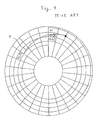
- This MCAV system is arranged such that the recording medium is radially divided from the inner circumference to the outer circumference into a plurality of groups each of which has a constant number of sectors, and in each of the groups one or more sectors are increased or decreased to perform the division into the groups so that the recording pits are formed constantly at the inner and outer circumferences thereof.
- a write-and-verify operation is performed after recording.
- Fig. 1 showing a general arrangement of an optical disc system.
- data outputted from a host computer 1 to be written are inputted through a host interface 2 to a buffer memory 4 of a controller 3.
- the data are supplied to an EDAC 5 in units of an amount corresponding to one sector of the recording medium where an error-correction code is added.
- the EDAC 5 acts as a bit error detection and correction circuit in which a predetermined bit is inserted into the data in accordance with an adequate calculation equation so as to find the error bit position when an error such as bit inversion occurs on reproduction. Thereafter, the data are supplied to a MODEM 6 for modulation to a code suitable for the recording on the optical disc and demodulation of the reproduced signal, and then supplied to a drive unit 7 to be written through a recording/reproducing head 8 on a recording medium 9.
- the MODEM 6 functions as a modulation and demoduation circuit to perform the modulation for recording to the recording medium 9 and perform the demodulation of the signal read out from the recording medium 9 to the original data before the recording.
- the data stored in the buffer memory 4 is kept as it is until the sector in which the data are recorded is completely verified, and when a problem is found by the verification, the data kept in the buffer memory 4 are transferred to the drive unit 7 for a changing process to other sectors.
- Fig. 2 is an illustration of a process of a write-and-verify command corresponding to the number of the recording sectors where vertical axis represents the time (rotational speed) and horizontal axis represents the number of the recording sectors.
- the buffer memory 4 has a capacity corresponding to 48 sectors
- the data to be stored in the recording medium 9 correspond to 56 sectors
- the overall 48 sector capacity is used for the write-and-verify operation
- the data transfer is once interrupted and the data corresponding to 48 sectors stored in the buffer memory 4 are recorded on the recording medium 9 from a sector m (logic block address) up to a sector m+47. This procedure is indicated by a character A in Fig. 2.
- the data of the buffer memory 4 corresponding to the sector are supplied to the drive unit 7 side so as to be recorded in a sector-changing area on the recording medium 9. Thereafter, the portion of the buffer memory 4 corresponding to the changed sector is released and the next data are transferred from the host computer 1 to this released portion.
- the recording/reproducing head 8 of the drive unit 7 seeks for the next sector m+48, and the remaining data corresponding to 8 sectors are transferred through the EDAC 5 and the MODEM 6 to the drive unit 7.
- the writing operation F, seeking operation G, verify-sector waiting operation H and verification J are successively effected as illustrated in Fig. 2.
- Fig. 3 shows a state that the data to be recorded are divided into a plurality of blocks and the number of the sectors in one track is 28 under the condition that the capacity of the buffer memory for the writing operation A and the verification is fixed to 48 sectors. Further, in Fig. 3, for writing data by 48 sectors from the sector m, the seeking operation is performed from the sector (m+47), taken after writing the data corresponding to one revolution (28 sectors) plus 20 sectors, to the sector m for the verification. During the seeking operation, a preparation for the verification is made.
- the time period for the seeking operation and the verification preparation is indicated by T in Fig. 3.
- T the time period for the seeking operation and the verification preparation.
- the first verified sector m is immediately detectable after the completion of the verification preparation and hence the sector-waiting time becomes at a minimum.
- Fig. 4 shows the case that the number of the sectors in one track is 26 under the condition that the buffer memory capacity for the writing operation A and the verification D is fixed to 48, and further shows a state that the first sector m for the verification is passed when the verification preparation (seeking operation) is effected after 48 sectors are written.
- the verification is performed after elapse of the time period corresponding to one revolution and hence the verification waiting time is lengthened by the time approximately corresponding to one revolution to cause the execution time to be delayed.
- the verification waiting time is always constant in the same group but the execution time is rapidly shortened or lengthened when the verification is effected over different groups, and hence the operation viewed from the host computer 1 becomes unstable and further the write-and-verify execution time becomes long because the sector-waiting time becomes long.
- the sector-waiting time is lengthened to decrease the execution speed in accordance with increase in the amount of the procedure (erase, recording, confirmation and others) in the write-and-verify operation and the amount of information to be recorded and further in accordance with decrease in the capacity of the buffer memory in the controller 3.
- an information recording/reproducing apparatus for recording and reproducing information on and from a recording medium having thereon spiral or coaxial tracks and rotatable by rotating means
- the information recording/reproducing apparatus comprising: memory means for temporalily storing the information; recording/reproducing means coupled to the memory means for recording and reproducing the information stored in the memory means on said recording medium; and control means coupled to the recording/reproducing means for controlling the recording/reproducing means to record the information on the recording medium and to reproduce the information from the recording medium so as to verify the recorded information, said control means dividing data, which is the information to be recorded, into two or more blocks and varying the length of the data to divided in accordance with the number of sectors in each of the tracks formed on the recording medium.
- the length of the data to be divided is determined so that a sector-waiting time taken while the recorded data are reproduced for the verification becomes at a minimum, and the coaxial or spiral tracks of the recording medium are divided radially into a plurality of groups, and the number of the sectors per track in each of the drivided groups is successively increased and decreased in proportion to a position of the recording medium in the radial directions.
- an information recording/reproducing apparatus is arranged to record and reproduce information on a disc-like recording medium having spiral or coaxial tracks, this tracks being radially divided into a plurality of groups and the number of sectors in the group being increased and decreased in the radial directions.
- the disc-like recording medium is rotatable by a rotating means and the information is recorded and reproduced through a head means.
- the information recording/reproducing apparatus has a function to verify the recorded in formation on the recording medium. When dividing a series of information into two or more blocks for the recording, the length of the data to be divided is arranged to be varied in accordance with the number of the sectors in one track.
- This arrangement allows the verification-waiting time to become at a minimum and permits the execution speed viewed from the host computer to become stable and allows the execution speed to becomes increased. Further, in the case of using different kinds of recording mediums, when dividing a series of information to be recorded and recording then, the length of the data to be divided is arranged to vary in accordance with the number of the sectors in one track. Thus, the verification-waiting time can be set to become at a minimum in the respective kinds of recording mediums and the execution speed can be increased. Further, the length of the data to be divided is set so that the sector-waiting time occurring while the recording data are reproduced by means the verifying means becomes at a minimum, whereby the verification-waiting time can further be decreased so as to increase the execution speed.
- Figs. 5 and 6 are illustrations for describing the case that, under the condition that the buffer memory 4 of the controller 3 shown in Fig. 1 stores data corresponding to 48 sectors and the number of the sectors in one track of the recording medium 9 is 26, the write-and-verify operation is effected for the data corresponding to 56 sectors started from the sector m.
- the 56 sectors to be written is greater than the capacity of the buffer memory 4 of the controller 3, and therefore the writing operation is executed with division into two blocks.
- Fig. 5 is an illustration for describing the write-and-verify operation under the above-mentioned conditions and Fig.
- FIG. 6 is an illustration for describing the write-and-verify operation for the data corresponding to 44 sectors when the number of the sectors in one track is 26.
- the seeking operation (verification preparation time) is indicated by an arrow T.
- the verification is performed by the recording/reproducing head 8 after writing from the sector m up to the sector m+43, and therefore the verification preparation is made while the seeking operation is effected toward a track including the sector m.
- the detection of the sector m can immediately be executed, and therefore the sector-waiting time required until the completion of the seeking operation and the verification preparation can become at a minimum.
- Fig. 5 shows the procedure of the write-and-verify command corresponding to the number of the recording sectors, where the vertical axis represents the time (rotational speed) and the horizontal axis represents the number of the sectors.
- the number of the sectors in the first writing operation A is not fixed but varies in accordance with each of the groups, and the amount of the writing operation A is set to 44 sectors, for example.
- the first sector m of the verification is detectable and hence the sector-waiting time C following the verification preparation B has a minimum.
- the verification D is executed so that the first write-and-verify operation is completed.
- the writing operation (F), seeking operation G, verifying-sector-waiting operation H and verification are similarly effected for the remaining 12 sectors, thereby completing the entire write-and-verify operation.
- the following table shows the optimal value (sector) in each of the different groups of the write-and-verify sectors.
- Fig. 7 is a flow chart showing the operation of the information recording/reproducing apparatus according to this invention.
- the optimal value to be written at a time is first determined on the basis of the capacity of the buffer memory and the number of the sectors in one track, then followed by performing the seeking operation to the writing track and the writing preparation.
- the data is written, then followed by performing the seeking operation to the verification track and at the same time performing the verification preparation.
- the verifying sector waiting operation the verification is effected. Thereafter, if there are sectors to be recorded. If so, the operational flow returns to the initial process.
- An information recording/reproducing apparatus for recording and reproducing information on and from a recording medium having thereon spiral or coaxial tracks and rotatable by a rotating device.
- the information recording/reproducing apparatus comprises a memory for temporalily storing the information, and a recording/reproducing drive unit coupled to the memory for recording and reproducing the information stored in the memory means on the recording medium.
- a control unit coupled to the meory and further the recording/reproducing drive unit for controlling the recording of the information on the recording medium on the basis of the data stored in the memory and the reproduction of the information therefrom to verify the recorded information.
- the control unit divides data, which is the information to be recorded, into two or more blocks and varies the length of the data to divided in accordance with the number of sectors in each of the tracks formed on the said recording medium.
Applications Claiming Priority (2)
| Application Number | Priority Date | Filing Date | Title |
|---|---|---|---|
| JP2001221A JP2593721B2 (ja) | 1990-01-08 | 1990-01-08 | 情報記録再生装置 |
| JP1221/90 | 1990-01-08 |
Publications (2)
| Publication Number | Publication Date |
|---|---|
| EP0437202A1 true EP0437202A1 (fr) | 1991-07-17 |
| EP0437202B1 EP0437202B1 (fr) | 1996-04-17 |
Family
ID=11495413
Family Applications (1)
| Application Number | Title | Priority Date | Filing Date |
|---|---|---|---|
| EP91100058A Expired - Lifetime EP0437202B1 (fr) | 1990-01-08 | 1991-01-02 | Appareil d'enregistrement/de reproduction d'information et de vérification de l'information enregistrée |
Country Status (4)
| Country | Link |
|---|---|
| US (1) | US5239424A (fr) |
| EP (1) | EP0437202B1 (fr) |
| JP (1) | JP2593721B2 (fr) |
| DE (1) | DE69118718T2 (fr) |
Cited By (1)
| Publication number | Priority date | Publication date | Assignee | Title |
|---|---|---|---|---|
| EP0646917A1 (fr) * | 1993-09-30 | 1995-04-05 | Kabushiki Kaisha Toshiba | Support d'enregistrement de données |
Families Citing this family (6)
| Publication number | Priority date | Publication date | Assignee | Title |
|---|---|---|---|---|
| JPH0636473A (ja) * | 1992-07-16 | 1994-02-10 | Matsushita Electric Ind Co Ltd | 光情報記録装置及びその方法 |
| JP2772205B2 (ja) * | 1992-09-22 | 1998-07-02 | 北海道日本電気ソフトウェア株式会社 | データ領域生成方式 |
| JPH06203486A (ja) * | 1992-12-31 | 1994-07-22 | Sony Corp | 記録再生制御装置 |
| JPH07320410A (ja) * | 1994-03-30 | 1995-12-08 | Nikon Corp | 光ディスク記録方法及び装置 |
| JPH08328752A (ja) * | 1994-06-10 | 1996-12-13 | Canon Inc | 情報記録装置及び方法 |
| US20050080934A1 (en) | 2003-09-30 | 2005-04-14 | Cota-Robles Erik C. | Invalidating translation lookaside buffer entries in a virtual machine (VM) system |
Citations (5)
| Publication number | Priority date | Publication date | Assignee | Title |
|---|---|---|---|---|
| DE3612815A1 (de) * | 1985-04-17 | 1986-10-23 | Canon K.K., Tokio/Tokyo | Informationsaufzeichnungsverfahren |
| DE3704213A1 (de) * | 1986-02-20 | 1987-08-27 | Sharp Kk | Diskettenaufzeichnungsverfahren |
| US4791622A (en) * | 1983-09-19 | 1988-12-13 | Storage Technology Partners 11 | Optical data format employing resynchronizable data sectors |
| EP0364229A2 (fr) * | 1988-10-14 | 1990-04-18 | Sony Corporation | Méthode et appareil pour l'enregistrement de données |
| EP0383298A2 (fr) * | 1989-02-15 | 1990-08-22 | Sony Corporation | Appareil d'enregistrement et de reproduction de données |
-
1990
- 1990-01-08 JP JP2001221A patent/JP2593721B2/ja not_active Expired - Fee Related
- 1990-12-31 US US07/636,452 patent/US5239424A/en not_active Expired - Lifetime
-
1991
- 1991-01-02 DE DE69118718T patent/DE69118718T2/de not_active Expired - Fee Related
- 1991-01-02 EP EP91100058A patent/EP0437202B1/fr not_active Expired - Lifetime
Patent Citations (5)
| Publication number | Priority date | Publication date | Assignee | Title |
|---|---|---|---|---|
| US4791622A (en) * | 1983-09-19 | 1988-12-13 | Storage Technology Partners 11 | Optical data format employing resynchronizable data sectors |
| DE3612815A1 (de) * | 1985-04-17 | 1986-10-23 | Canon K.K., Tokio/Tokyo | Informationsaufzeichnungsverfahren |
| DE3704213A1 (de) * | 1986-02-20 | 1987-08-27 | Sharp Kk | Diskettenaufzeichnungsverfahren |
| EP0364229A2 (fr) * | 1988-10-14 | 1990-04-18 | Sony Corporation | Méthode et appareil pour l'enregistrement de données |
| EP0383298A2 (fr) * | 1989-02-15 | 1990-08-22 | Sony Corporation | Appareil d'enregistrement et de reproduction de données |
Cited By (2)
| Publication number | Priority date | Publication date | Assignee | Title |
|---|---|---|---|---|
| EP0646917A1 (fr) * | 1993-09-30 | 1995-04-05 | Kabushiki Kaisha Toshiba | Support d'enregistrement de données |
| US5850381A (en) * | 1993-09-30 | 1998-12-15 | Kabushiki Kaisha Toshiba | Method of recording information on a disc by recording information at interleaved sectors |
Also Published As
| Publication number | Publication date |
|---|---|
| EP0437202B1 (fr) | 1996-04-17 |
| US5239424A (en) | 1993-08-24 |
| JP2593721B2 (ja) | 1997-03-26 |
| DE69118718T2 (de) | 1997-04-17 |
| DE69118718D1 (de) | 1996-05-23 |
| JPH03205657A (ja) | 1991-09-09 |
Similar Documents
| Publication | Publication Date | Title |
|---|---|---|
| JPH0378649B2 (fr) | ||
| US5257248A (en) | Information recording apparatus capable of efficiently verifying recording information | |
| US4942486A (en) | Recording disk having read-only recording area and writable recording area and a driving apparatus therefor | |
| JP3254340B2 (ja) | 記録再生装置および記録再生装置のための欠陥処理方法 | |
| EP0424910B1 (fr) | Appareil d'enregistrement et de reproduction d'information pour l'enregistrement d'information et pour la vérification de l'information enregistrée | |
| US5450384A (en) | Fast formatting of media in an optical library | |
| EP0437202B1 (fr) | Appareil d'enregistrement/de reproduction d'information et de vérification de l'information enregistrée | |
| US5161143A (en) | Information recording-reproducing apparatus for optimizing data transfer | |
| JPH076002A (ja) | 情報記録再生装置における交替処理方法 | |
| EP0490400B1 (fr) | Appareil à mémoriser de l'information | |
| JPH06314174A (ja) | 情報記録媒体及び情報記録再生装置 | |
| WO1994019802A1 (fr) | Appareil d'enregistrement sur disque | |
| JPH07320410A (ja) | 光ディスク記録方法及び装置 | |
| JPH04252427A (ja) | 光ディスク及び光ディスク記録再生装置 | |
| JP2728949B2 (ja) | 光ディスクサブシステムの制御方式 | |
| JP2616097B2 (ja) | 情報記録再生装置 | |
| JP3231803B2 (ja) | データ記録再生方法 | |
| JPH02235264A (ja) | 電子ファイル装置 | |
| JP2746311B2 (ja) | 情報記録装置 | |
| JPH0660550A (ja) | ディスク装置 | |
| JPH08106722A (ja) | 情報記録再生装置 | |
| JPH04178976A (ja) | 光磁気ディスクからのデータ読取方法 | |
| JPH05325422A (ja) | 情報記録再生装置 | |
| JPH02312069A (ja) | 光ディスクにおける記録方式 | |
| JPH0594672A (ja) | 情報記録再生装置 |
Legal Events
| Date | Code | Title | Description |
|---|---|---|---|
| PUAI | Public reference made under article 153(3) epc to a published international application that has entered the european phase |
Free format text: ORIGINAL CODE: 0009012 |
|
| 17P | Request for examination filed |
Effective date: 19910102 |
|
| AK | Designated contracting states |
Kind code of ref document: A1 Designated state(s): DE FR GB |
|
| 17Q | First examination report despatched |
Effective date: 19940526 |
|
| RAP1 | Party data changed (applicant data changed or rights of an application transferred) |
Owner name: MATSUSHITA ELECTRIC INDUSTRIAL CO., LTD. |
|
| GRAA | (expected) grant |
Free format text: ORIGINAL CODE: 0009210 |
|
| AK | Designated contracting states |
Kind code of ref document: B1 Designated state(s): DE FR GB |
|
| REF | Corresponds to: |
Ref document number: 69118718 Country of ref document: DE Date of ref document: 19960523 |
|
| ET | Fr: translation filed | ||
| PLBE | No opposition filed within time limit |
Free format text: ORIGINAL CODE: 0009261 |
|
| STAA | Information on the status of an ep patent application or granted ep patent |
Free format text: STATUS: NO OPPOSITION FILED WITHIN TIME LIMIT |
|
| 26N | No opposition filed | ||
| REG | Reference to a national code |
Ref country code: GB Ref legal event code: IF02 |
|
| PGFP | Annual fee paid to national office [announced via postgrant information from national office to epo] |
Ref country code: GB Payment date: 20051228 Year of fee payment: 16 |
|
| PGFP | Annual fee paid to national office [announced via postgrant information from national office to epo] |
Ref country code: DE Payment date: 20060103 Year of fee payment: 16 |
|
| PGFP | Annual fee paid to national office [announced via postgrant information from national office to epo] |
Ref country code: FR Payment date: 20060110 Year of fee payment: 16 |
|
| PG25 | Lapsed in a contracting state [announced via postgrant information from national office to epo] |
Ref country code: DE Free format text: LAPSE BECAUSE OF NON-PAYMENT OF DUE FEES Effective date: 20070801 |
|
| GBPC | Gb: european patent ceased through non-payment of renewal fee |
Effective date: 20070102 |
|
| REG | Reference to a national code |
Ref country code: FR Ref legal event code: ST Effective date: 20070930 |
|
| PG25 | Lapsed in a contracting state [announced via postgrant information from national office to epo] |
Ref country code: GB Free format text: LAPSE BECAUSE OF NON-PAYMENT OF DUE FEES Effective date: 20070102 |
|
| PG25 | Lapsed in a contracting state [announced via postgrant information from national office to epo] |
Ref country code: FR Free format text: LAPSE BECAUSE OF NON-PAYMENT OF DUE FEES Effective date: 20070131 |