EP0436360A2 - Dispenser cathode structure for use in electron gun - Google Patents
Dispenser cathode structure for use in electron gun Download PDFInfo
- Publication number
- EP0436360A2 EP0436360A2 EP90314024A EP90314024A EP0436360A2 EP 0436360 A2 EP0436360 A2 EP 0436360A2 EP 90314024 A EP90314024 A EP 90314024A EP 90314024 A EP90314024 A EP 90314024A EP 0436360 A2 EP0436360 A2 EP 0436360A2
- Authority
- EP
- European Patent Office
- Prior art keywords
- sleeve
- cathode
- heat shielding
- shielding tube
- electron gun
- Prior art date
- Legal status (The legal status is an assumption and is not a legal conclusion. Google has not performed a legal analysis and makes no representation as to the accuracy of the status listed.)
- Granted
Links
Images


Classifications
-
- H—ELECTRICITY
- H01—ELECTRIC ELEMENTS
- H01J—ELECTRIC DISCHARGE TUBES OR DISCHARGE LAMPS
- H01J1/00—Details of electrodes, of magnetic control means, of screens, or of the mounting or spacing thereof, common to two or more basic types of discharge tubes or lamps
- H01J1/02—Main electrodes
- H01J1/13—Solid thermionic cathodes
- H01J1/20—Cathodes heated indirectly by an electric current; Cathodes heated by electron or ion bombardment
- H01J1/28—Dispenser-type cathodes, e.g. L-cathode
-
- H—ELECTRICITY
- H01—ELECTRIC ELEMENTS
- H01J—ELECTRIC DISCHARGE TUBES OR DISCHARGE LAMPS
- H01J29/00—Details of cathode-ray tubes or of electron-beam tubes of the types covered by group H01J31/00
- H01J29/02—Electrodes; Screens; Mounting, supporting, spacing or insulating thereof
- H01J29/04—Cathodes
-
- H—ELECTRICITY
- H01—ELECTRIC ELEMENTS
- H01J—ELECTRIC DISCHARGE TUBES OR DISCHARGE LAMPS
- H01J1/00—Details of electrodes, of magnetic control means, of screens, or of the mounting or spacing thereof, common to two or more basic types of discharge tubes or lamps
- H01J1/02—Main electrodes
- H01J1/13—Solid thermionic cathodes
- H01J1/20—Cathodes heated indirectly by an electric current; Cathodes heated by electron or ion bombardment
- H01J1/26—Supports for the emissive material
Definitions
- the present invention relates to a cathode structure for use in an electron gun, and particularly to an improved structure of a dispenser cathode for use in a colour cathode ray tube.
- thermoelectron emissive material is impregnated in a porous base 1 which is made of heat resistance material such as, for example, tungsten.
- the porous base is a thermoelectron emissive source and is contained within a reservoir 2 which is in the form of a cup.
- This reservoir 2 is disposed within the upper portion of a sleeve 3 receiving a heater 6.
- the sleeve 3 is supported by a holder 4 connected to the lower portion thereof, and is enclosed by a large-caliber heat shielding tube 5.
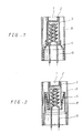
- FIG.2 The construction of another impregnated dispenser cathode illustrated in FIG.2 is similar to the impregnated structure described above.
- This impregnated dispenser cathode comprises a reservoir 2 containing a porous base 1, a sleeve 3 for supporting and fixing the reservoir and receiving a heater 6, a suspending ribbon 8 whose lower portion is welded to the lower end of the sleeve and whose upper portion is welded to the upper end of a large-diameter holder 4, and a heat shielding tube 5 which surrounds the sleeve 3 and is welded to the holder 4.
- thermoelectron emissive source of the cavity reservoir type cathode comprises thermoelectron emissive material such as, for example, tungsten, barium calcium aluminate, etc. which is contained in the reservoir disposed within the upper portion of the sleeve, and a porous base which is, disposed on the thermoelectron emissive material and is welded to the reservoir.
- the dispenser cathodes having the above-mentioned constructions have much higher current density than that of the ordinary oxide cathode ray tube, so that they are adapted to be used in the electron gun of a large-scale cathode ray tube or a projecting tube, etc.
- the withstand voltage characteristic at the initial operation is poor and the radiating state of the electron beam is unstable.
- thermoelectron emissive source of the conventional dispenser cathode i.e. a porous base, which is positioned adjacent to the first electrode of an electron gun, approaches rapidly to the first electrode at the initial operation. This approach of the porous base 1 to the first electrode results from the structural defect of the cathode.
- the sleeve 3 supported by a holder 4 and receiving a heater 6 therein as shown in FIGS.1 and 2 is thermally expanded by heat from the heater towards the first electrode disposed adjacent to the upper portion of the sleeve, starting from the holder 4 disposed in the lower portion of the sleeve.
- the cut-off voltage for controlling the electron beam varies abnormally. As a result, the white balance of image in the screen fails.
- the thermal deformation of the cathode is considered in a step of control of the cathode ray tube, so as to control the characteristic of the cathode ray tube.
- the control of the cathode ray tube is very complicated, and also the stabilization time of picture quality at the initial operation is lengthened even if the control is carried out comparatively well.
- a dispenser cathode for an electron gun comprising: a reservoir for reserving thermoelectron emissive material; a sleeve which is provided with an outward flange at the top thereof and receives and fixes the reservoir within the upper portion thereof; a heat shielding tube provided with inward flange at the top thereof which is corresponding and overlapped with the flange of the sleeve and is welded thereto; and a holder for supporting and fixing the heat shielding tube.
- a porous base 1 impregnated with thermoelectron emissive material is contained within a reservoir 2.
- the reservoir 2 is inserted into and fixed to the upper portion of a sleeve 3 which is provided with an outward flange 3a at the top thereof and receives a heater 6 therein.
- a heat shielding tube 5 of larger caliber is provided with another flange 5a corresponding to the flange of the sleeve 3 at the top thereof.
- the heat shielding tube 5 encloses the sleeve 3 and is coupled to this sleeve by overlapping and welding the flange 3a with the flange 5a.
- the heat shielding tube 5 is fixed to and supported by a holder 4 disposed below the shielding tube 5.
- a porous base 1 impregnated with thermoelectron emissive material is disposed within a reservoir 2, and the reservoir is inserted into and fixed to the upper portion of a sleeve 3 which is provided with a flange 3a at the top thereof and receives a heater 6 therein. Then, this sleeve 3 is welded and fixed to a large-caliber heat shielding tube 5 which is provided with an inward flange 5a at the top thereof. At this time, the sleeve 3 and the heat shielding tube 5 are connected to each other by the flanges 3a and 5a which are nested and welded to each other. Finally, the heat shielding tube 5 is supported and fixed to a holder 4 by a suspending ribbon 8 the lower end of which is welded to the lower portion of the heat shielding tube 5 and upper end of which is welded to the upper end of the holder 4.
- the flanges 3a and 5a are formed respectively on the sleeve 3 and on the heat shielding tube 5, along the entire top circumferences thereof. But they can be formed locally in such a manner that a plurality of fragmentary flanges 3a' and 5a' are formed at corresponding positions to each other.
- a sleeve subject to a large heat expansion is fixed directly to a heat shielding tube, in such a manner that the top end of the sleeve is fixed to the top end of the heat shielding tube and lower end of the sleeve is kept free. Accordingly, when the sleeve undergoes thermal expansion by heat from the heater, it expands in the opposite direction from the first electrode of an electron gun. As a result, the relative movement between the porous base and the first electrode of an electron gun is minimized.
- the change of the cut-off characteristic in the electron gun can be reduced at the initial operation of the cathode ray tube.
- the initial operation characteristic of the electron gun is stabilized as soon as possible, and the white balance of the image is improved.
- it is possible to manufacture an electron gun having little change of several characteristics at the initial operation and also it is possible to provide a cathode ray tube having stable initial operation characteristic and stable picture quality for the users.
- thermoelectron emissive material is stored in a reservoir and a porous base body is fixed on the thermoelectron emissive material.
Abstract
Description
- The present invention relates to a cathode structure for use in an electron gun, and particularly to an improved structure of a dispenser cathode for use in a colour cathode ray tube.
- In U.S. Patent Nos. 4,165,473, 4,400,648, 4,737,679 and 4,823,044, the conventional dispenser cathode structures used in electron guns are explained in detail. There are two types of dispenser cathodes for electron guns, i.e. an impregnated cathode and a cavity reservoir type cathode. U.S. Pat. Nos. 4,165,473, 4,400,648 and 4,737,679 relate to the impregnated cathode, and U.S. Pat. No. 4,823,044 relates to the cavity reservoir type cathode.
- The structures of impregnated cathodes are shown in FIGS.1 and 2 of the accompanying drawings. In the impregnated cathode as illustrated in FIG. 1, thermoelectron emissive material is impregnated in a
porous base 1 which is made of heat resistance material such as, for example, tungsten. The porous base is a thermoelectron emissive source and is contained within areservoir 2 which is in the form of a cup. Thisreservoir 2 is disposed within the upper portion of asleeve 3 receiving aheater 6. Thesleeve 3 is supported by a holder 4 connected to the lower portion thereof, and is enclosed by a large-caliberheat shielding tube 5. - The construction of another impregnated dispenser cathode illustrated in FIG.2 is similar to the impregnated structure described above. This impregnated dispenser cathode comprises a
reservoir 2 containing aporous base 1, asleeve 3 for supporting and fixing the reservoir and receiving aheater 6, a suspendingribbon 8 whose lower portion is welded to the lower end of the sleeve and whose upper portion is welded to the upper end of a large-diameter holder 4, and aheat shielding tube 5 which surrounds thesleeve 3 and is welded to the holder 4. - By contrast, a cavity reservoir type cathode has a different thermoelectron emissive source from the aforesaid porous base which is contained in the cup-shaped reservoir. The thermoelectron emissive source of the cavity reservoir type cathode comprises thermoelectron emissive material such as, for example, tungsten, barium calcium aluminate, etc. which is contained in the reservoir disposed within the upper portion of the sleeve, and a porous base which is, disposed on the thermoelectron emissive material and is welded to the reservoir.
- The dispenser cathodes having the above-mentioned constructions have much higher current density than that of the ordinary oxide cathode ray tube, so that they are adapted to be used in the electron gun of a large-scale cathode ray tube or a projecting tube, etc. However, in the electron gun adopting such conventional dispenser cathode, the withstand voltage characteristic at the initial operation is poor and the radiating state of the electron beam is unstable. These problems are caused since thermoelectron emissive source of the conventional dispenser cathode, i.e. a porous base, which is positioned adjacent to the first electrode of an electron gun, approaches rapidly to the first electrode at the initial operation. This approach of the
porous base 1 to the first electrode results from the structural defect of the cathode. In more detail, thesleeve 3 supported by a holder 4 and receiving aheater 6 therein as shown in FIGS.1 and 2, is thermally expanded by heat from the heater towards the first electrode disposed adjacent to the upper portion of the sleeve, starting from the holder 4 disposed in the lower portion of the sleeve. As described above, if the sleeve expands and the cathode approaches the first electrode, the cut-off voltage for controlling the electron beam varies abnormally. As a result, the white balance of image in the screen fails. - In all electron guns, it is inevitable for some parts of the cathode to be shifted by thermal expansion, thereby resulting in the above problems. In the conventional cathode ray tube, to obviate the above problems, the thermal deformation of the cathode is considered in a step of control of the cathode ray tube, so as to control the characteristic of the cathode ray tube. However, in the case of a cathode ray tube with a cathode having a large change of the position through thermal expansion, the control of the cathode ray tube is very complicated, and also the stabilization time of picture quality at the initial operation is lengthened even if the control is carried out comparatively well.
- It is an object of the present invention to provide an improved dispenser cathode for use in an electron gun, which can greatly improve withstand voltage characteristic and white balance.
- According to the present invention there is provided a dispenser cathode for an electron gun comprising:
a reservoir for reserving thermoelectron emissive material;
a sleeve which is provided with an outward flange at the top thereof and receives and fixes the reservoir within the upper portion thereof;
a heat shielding tube provided with inward flange at the top thereof which is corresponding and overlapped with the flange of the sleeve and is welded thereto; and
a holder for supporting and fixing the heat shielding tube. - Embodiments of the present invention will now be described, by way of example, with reference to the accompanying drawings, in which:
- FIGS. 1 and 2 are sectional views of impregnated cathodes, a kind of the conventional dispenser cathode;
- FIG.3 is a sectional view of a preferred embodiment of the dispenser cathode according to the present invention;
- FIG.4 is a sectional view of another preferred embodiment of the dispenser cathode according to the present invention; and
- FIG.5 is a sectional view of a further embodiment of the dispenser cathode of the present invention.
- In the dispenser cathode of the present invention shown in FIG.3, a
porous base 1 impregnated with thermoelectron emissive material is contained within areservoir 2. Thereservoir 2 is inserted into and fixed to the upper portion of asleeve 3 which is provided with anoutward flange 3a at the top thereof and receives aheater 6 therein. Aheat shielding tube 5 of larger caliber is provided with anotherflange 5a corresponding to the flange of thesleeve 3 at the top thereof. Theheat shielding tube 5 encloses thesleeve 3 and is coupled to this sleeve by overlapping and welding theflange 3a with theflange 5a. Finally, theheat shielding tube 5 is fixed to and supported by a holder 4 disposed below theshielding tube 5. - In another dispenser cathode of the present invention shown in FIG.4, a
porous base 1 impregnated with thermoelectron emissive material is disposed within areservoir 2, and the reservoir is inserted into and fixed to the upper portion of asleeve 3 which is provided with aflange 3a at the top thereof and receives aheater 6 therein. Then, thissleeve 3 is welded and fixed to a large-caliberheat shielding tube 5 which is provided with aninward flange 5a at the top thereof. At this time, thesleeve 3 and theheat shielding tube 5 are connected to each other by theflanges heat shielding tube 5 is supported and fixed to a holder 4 by a suspendingribbon 8 the lower end of which is welded to the lower portion of theheat shielding tube 5 and upper end of which is welded to the upper end of the holder 4. - In the above preferred embodiments, the
flanges sleeve 3 and on theheat shielding tube 5, along the entire top circumferences thereof. But they can be formed locally in such a manner that a plurality offragmentary flanges 3a' and 5a' are formed at corresponding positions to each other. - Unlike the conventional dispenser cathode, in the impregnated cathode according to the present invention, a sleeve subject to a large heat expansion is fixed directly to a heat shielding tube, in such a manner that the top end of the sleeve is fixed to the top end of the heat shielding tube and lower end of the sleeve is kept free. Accordingly, when the sleeve undergoes thermal expansion by heat from the heater, it expands in the opposite direction from the first electrode of an electron gun. As a result, the relative movement between the porous base and the first electrode of an electron gun is minimized. Moreover, in the case of a dispenser cathode in which the sleeve and heat shielding tube have fragmentary flanges, the heat transfer through the flanges is effectively decreased, so that the shift of the cathode by heat deformation can be minimized.
- With dispenser cathodes having the abovementioned structural characteristic, the change of the cut-off characteristic in the electron gun can be reduced at the initial operation of the cathode ray tube. Thus, the initial operation characteristic of the electron gun is stabilized as soon as possible, and the white balance of the image is improved. In other words, it is possible to manufacture an electron gun having little change of several characteristics at the initial operation, and also it is possible to provide a cathode ray tube having stable initial operation characteristic and stable picture quality for the users.
- The above mentioned preferred embodiments of the present invention concentrates on the impregnated cathode in detail. However, the present invention may be also applied to a cavity reservoir type cathode in which the thermoelectron emissive material is stored in a reservoir and a porous base body is fixed on the thermoelectron emissive material.
Claims (3)
- A dispenser cathode for an electron gun comprising:
a sleeve (3);
a reservoir (2) for thermoelectron emissive material (1) fixed inside an upper portion of said sleeve;
a heat shielding tube (5) whose upper portion is connected with the upper portion of said sleeve via connecting means; and
a holder (4) for supporting said heat shielding tube. - A dispenser cathode for an electron gun as claimed in claim 1, wherein said connecting means comprise a flange (3a) at an upper portion of said sleeve (3), and another corresponding flange (5a) in the upper portion of said heat shielding tube ,said flange of the heat shielding tube being welded to said flange of said sleeve.
- A dispenser cathode for an electron gun as claimed in claim 2, wherein said sleeve (3) and said heat shielding tube (5) have a plurality of corresponding flanges (3a', 5a') in the respective upper portions of said sleeve (3) and heat shielding tube (5).
Applications Claiming Priority (2)
| Application Number | Priority Date | Filing Date | Title |
|---|---|---|---|
| KR8920770 | 1989-12-31 | ||
| KR1019890020770A KR0147542B1 (en) | 1989-12-31 | 1989-12-31 | Impregnated cathode for electron tube |
Publications (3)
| Publication Number | Publication Date |
|---|---|
| EP0436360A2 true EP0436360A2 (en) | 1991-07-10 |
| EP0436360A3 EP0436360A3 (en) | 1991-11-21 |
| EP0436360B1 EP0436360B1 (en) | 1995-04-05 |
Family
ID=19294811
Family Applications (1)
| Application Number | Title | Priority Date | Filing Date |
|---|---|---|---|
| EP90314024A Expired - Lifetime EP0436360B1 (en) | 1989-12-31 | 1990-12-20 | Dispenser cathode structure for use in electron gun |
Country Status (5)
| Country | Link |
|---|---|
| US (1) | US5113110A (en) |
| EP (1) | EP0436360B1 (en) |
| JP (1) | JPH04262343A (en) |
| KR (1) | KR0147542B1 (en) |
| DE (1) | DE69018425T2 (en) |
Cited By (6)
| Publication number | Priority date | Publication date | Assignee | Title |
|---|---|---|---|---|
| FR2691577A1 (en) * | 1992-05-22 | 1993-11-26 | Sony Corp | Cathode assembly for CRT electron gun - has protective screen around cathode emitter between emitter and hole in insulator support of cylindrical grid electrode |
| EP0641006A1 (en) * | 1993-08-24 | 1995-03-01 | Samsung Display Devices Co., Ltd. | Cathode for an electron tube |
| EP0848405A2 (en) * | 1996-12-11 | 1998-06-17 | Lg Electronics Inc. | Low power impregnated cathode of cathode-ray tube |
| FR2762712A1 (en) * | 1997-04-25 | 1998-10-30 | Thomson Tubes & Displays | CATHODE STRUCTURE FOR CATHODE RAY TUBE |
| US6242852B1 (en) | 1998-05-08 | 2001-06-05 | Sony Corporation | Electron gun |
| FR2895144A1 (en) * | 2005-12-16 | 2007-06-22 | Thomson Licensing Sas | Cathode support eyelet for electron gun of e.g. picture tube, has body with consolidation elements joining flange and body, where consolidation elements have maximum diameter lesser than diameter of hole of base |
Families Citing this family (5)
| Publication number | Priority date | Publication date | Assignee | Title |
|---|---|---|---|---|
| FR2741997B1 (en) * | 1995-12-05 | 1998-01-09 | Thomson Tubes & Displays | CATHODE STRUCTURE FOR CATHODE RAY TUBE |
| US20030025435A1 (en) * | 1999-11-24 | 2003-02-06 | Vancil Bernard K. | Reservoir dispenser cathode and method of manufacture |
| CN1956124B (en) * | 2005-10-27 | 2010-07-21 | 中国科学院电子学研究所 | High efficient cathode assembly |
| CN107452577B (en) * | 2017-06-13 | 2023-05-12 | 湖北汉光科技股份有限公司 | Manufacturing method of klystron electron gun thin wall side heat shield part |
| CN110931328B (en) * | 2019-12-06 | 2022-04-19 | 中国电子科技集团公司第十二研究所 | Cathode heater assembly |
Citations (3)
| Publication number | Priority date | Publication date | Assignee | Title |
|---|---|---|---|---|
| DE1132256B (en) * | 1961-12-27 | 1962-06-28 | Siemens Ag | Cathode for electrical discharge vessels and process for their manufacture |
| US3186786A (en) * | 1961-06-01 | 1965-06-01 | Bell Telephone Labor Inc | Method for processing oxide coated cathodes |
| US3467879A (en) * | 1966-03-08 | 1969-09-16 | Philips Corp | Planar dispenser cathode assembly with a cap member to which an electronemissive,tubular heater,and rodshaped support members are clamped |
Family Cites Families (9)
| Publication number | Priority date | Publication date | Assignee | Title |
|---|---|---|---|---|
| US3159461A (en) * | 1958-10-20 | 1964-12-01 | Bell Telephone Labor Inc | Thermionic cathode |
| US3441779A (en) * | 1966-04-06 | 1969-04-29 | Siemens Ag | Cathode having an end face carrier for an emission substance and the production thereof |
| DE1614495B1 (en) * | 1967-04-10 | 1971-03-11 | Siemens Ag | MEDIUM HEATED STORAGE CATHODE FOR ELECTRIC DISCHARGE VESSELS |
| DE1614566B1 (en) * | 1967-07-17 | 1970-11-05 | Siemens Ag | Indirectly heated supply cathode, especially MK cathode |
| JPS5146877Y2 (en) * | 1973-08-02 | 1976-11-11 | ||
| US4165473A (en) * | 1976-06-21 | 1979-08-21 | Varian Associates, Inc. | Electron tube with dispenser cathode |
| JPS5652835A (en) * | 1979-10-01 | 1981-05-12 | Hitachi Ltd | Impregnated cathode |
| JPS61183838A (en) * | 1985-02-08 | 1986-08-16 | Hitachi Ltd | Impregnated type cathode |
| US4823044A (en) * | 1988-02-10 | 1989-04-18 | Ceradyne, Inc. | Dispenser cathode and method of manufacture therefor |
-
1989
- 1989-12-31 KR KR1019890020770A patent/KR0147542B1/en not_active IP Right Cessation
-
1990
- 1990-12-20 EP EP90314024A patent/EP0436360B1/en not_active Expired - Lifetime
- 1990-12-20 DE DE69018425T patent/DE69018425T2/en not_active Expired - Fee Related
- 1990-12-31 US US07/633,529 patent/US5113110A/en not_active Expired - Lifetime
-
1991
- 1991-01-04 JP JP3010328A patent/JPH04262343A/en active Pending
Patent Citations (3)
| Publication number | Priority date | Publication date | Assignee | Title |
|---|---|---|---|---|
| US3186786A (en) * | 1961-06-01 | 1965-06-01 | Bell Telephone Labor Inc | Method for processing oxide coated cathodes |
| DE1132256B (en) * | 1961-12-27 | 1962-06-28 | Siemens Ag | Cathode for electrical discharge vessels and process for their manufacture |
| US3467879A (en) * | 1966-03-08 | 1969-09-16 | Philips Corp | Planar dispenser cathode assembly with a cap member to which an electronemissive,tubular heater,and rodshaped support members are clamped |
Cited By (12)
| Publication number | Priority date | Publication date | Assignee | Title |
|---|---|---|---|---|
| FR2691577A1 (en) * | 1992-05-22 | 1993-11-26 | Sony Corp | Cathode assembly for CRT electron gun - has protective screen around cathode emitter between emitter and hole in insulator support of cylindrical grid electrode |
| NL9300874A (en) * | 1992-05-22 | 1993-12-16 | Sony Corp | CATHODE COMPOSITION AND ELECTRON GUN. |
| EP0641006A1 (en) * | 1993-08-24 | 1995-03-01 | Samsung Display Devices Co., Ltd. | Cathode for an electron tube |
| EP0848405A2 (en) * | 1996-12-11 | 1998-06-17 | Lg Electronics Inc. | Low power impregnated cathode of cathode-ray tube |
| EP0848405A3 (en) * | 1996-12-11 | 1998-08-05 | Lg Electronics Inc. | Low power impregnated cathode of cathode-ray tube |
| FR2762712A1 (en) * | 1997-04-25 | 1998-10-30 | Thomson Tubes & Displays | CATHODE STRUCTURE FOR CATHODE RAY TUBE |
| WO1998049704A1 (en) * | 1997-04-25 | 1998-11-05 | Thomson Tubes And Displays, S.A. | Cathode structure and electron gun for cathode ray tubes |
| US6369494B1 (en) | 1997-04-25 | 2002-04-09 | Thomson Tubes & Displays, S.A. | Cathode structure and electron gun for cathode ray tubes |
| US6242852B1 (en) | 1998-05-08 | 2001-06-05 | Sony Corporation | Electron gun |
| SG83126A1 (en) * | 1998-05-08 | 2001-09-18 | Sony Corp | Electron gun |
| NL1011975C2 (en) * | 1998-05-08 | 2004-02-10 | Sony Corp | Electron gun. |
| FR2895144A1 (en) * | 2005-12-16 | 2007-06-22 | Thomson Licensing Sas | Cathode support eyelet for electron gun of e.g. picture tube, has body with consolidation elements joining flange and body, where consolidation elements have maximum diameter lesser than diameter of hole of base |
Also Published As
| Publication number | Publication date |
|---|---|
| EP0436360B1 (en) | 1995-04-05 |
| JPH04262343A (en) | 1992-09-17 |
| DE69018425D1 (en) | 1995-05-11 |
| KR910013350A (en) | 1991-08-08 |
| US5113110A (en) | 1992-05-12 |
| DE69018425T2 (en) | 1995-11-09 |
| KR0147542B1 (en) | 1998-08-01 |
| EP0436360A3 (en) | 1991-11-21 |
Similar Documents
| Publication | Publication Date | Title |
|---|---|---|
| EP0436360B1 (en) | Dispenser cathode structure for use in electron gun | |
| US3983443A (en) | Vacuum electron device having directly-heated matrix-cathode-heater assembly | |
| EP0848405B1 (en) | Low power impregnated cathode of cathode-ray tube | |
| US5668434A (en) | Directly heated cathode for cathode ray tube | |
| US5289076A (en) | Cathode structure for a cathode ray tube | |
| RU2060569C1 (en) | Distributing cathode of electron gun | |
| US5131878A (en) | Process for manufacturing dispenser cathode | |
| US5703429A (en) | Directly heated cathode structure | |
| US5780959A (en) | Cathode structure for cathode ray tube | |
| US5117153A (en) | Cathode structure for electron gun | |
| RU2155409C2 (en) | Structure of directly heated cathode and process of its manufacture ( versions ) | |
| US2869017A (en) | Thermionic dispenser cathode | |
| GB2262650A (en) | Impregnated dispenser cathode and manufacture thereof. | |
| KR920006821Y1 (en) | A form structure of dispenser type cathode | |
| EP0534842A1 (en) | Cathode structure for an electron tube | |
| KR950010691Y1 (en) | Cathod of crt electron gun | |
| KR930007523Y1 (en) | Crt structure | |
| US20040140747A1 (en) | Cathode structure for color cathode ray tube | |
| KR920003290Y1 (en) | Cathode structure of crt | |
| KR200147987Y1 (en) | Pellet supporting structure of impregnation type cathode | |
| KR100230442B1 (en) | Cathode unit and color cathode ray tube using it | |
| JPS5943633Y2 (en) | Cathode ray tube cathode structure | |
| KR920002589Y1 (en) | Cathode assembly of crt | |
| KR100201144B1 (en) | Pellet supporting structure of impregnation type cathode | |
| KR100261736B1 (en) | Cathode structure for cathode ray tube |
Legal Events
| Date | Code | Title | Description |
|---|---|---|---|
| PUAI | Public reference made under article 153(3) epc to a published international application that has entered the european phase |
Free format text: ORIGINAL CODE: 0009012 |
|
| AK | Designated contracting states |
Kind code of ref document: A2 Designated state(s): DE FR GB NL |
|
| PUAL | Search report despatched |
Free format text: ORIGINAL CODE: 0009013 |
|
| AK | Designated contracting states |
Kind code of ref document: A3 Designated state(s): DE FR GB NL |
|
| 17P | Request for examination filed |
Effective date: 19920311 |
|
| 17Q | First examination report despatched |
Effective date: 19930527 |
|
| RAP1 | Party data changed (applicant data changed or rights of an application transferred) |
Owner name: SAMSUNG DISPLAY DEVICES CO., LTD. |
|
| GRAA | (expected) grant |
Free format text: ORIGINAL CODE: 0009210 |
|
| AK | Designated contracting states |
Kind code of ref document: B1 Designated state(s): DE FR GB NL |
|
| REF | Corresponds to: |
Ref document number: 69018425 Country of ref document: DE Date of ref document: 19950511 |
|
| ET | Fr: translation filed | ||
| PLBE | No opposition filed within time limit |
Free format text: ORIGINAL CODE: 0009261 |
|
| STAA | Information on the status of an ep patent application or granted ep patent |
Free format text: STATUS: NO OPPOSITION FILED WITHIN TIME LIMIT |
|
| 26N | No opposition filed | ||
| PGFP | Annual fee paid to national office [announced via postgrant information from national office to epo] |
Ref country code: FR Payment date: 20011212 Year of fee payment: 12 |
|
| PGFP | Annual fee paid to national office [announced via postgrant information from national office to epo] |
Ref country code: GB Payment date: 20011219 Year of fee payment: 12 |
|
| REG | Reference to a national code |
Ref country code: GB Ref legal event code: IF02 |
|
| PG25 | Lapsed in a contracting state [announced via postgrant information from national office to epo] |
Ref country code: GB Free format text: LAPSE BECAUSE OF NON-PAYMENT OF DUE FEES Effective date: 20021220 |
|
| GBPC | Gb: european patent ceased through non-payment of renewal fee |
Effective date: 20021220 |
|
| PG25 | Lapsed in a contracting state [announced via postgrant information from national office to epo] |
Ref country code: FR Free format text: LAPSE BECAUSE OF NON-PAYMENT OF DUE FEES Effective date: 20030901 |
|
| REG | Reference to a national code |
Ref country code: FR Ref legal event code: ST |
|
| PGFP | Annual fee paid to national office [announced via postgrant information from national office to epo] |
Ref country code: NL Payment date: 20071203 Year of fee payment: 18 |
|
| PGFP | Annual fee paid to national office [announced via postgrant information from national office to epo] |
Ref country code: DE Payment date: 20071213 Year of fee payment: 18 |
|
| NLV4 | Nl: lapsed or anulled due to non-payment of the annual fee |
Effective date: 20090701 |
|
| PG25 | Lapsed in a contracting state [announced via postgrant information from national office to epo] |
Ref country code: DE Free format text: LAPSE BECAUSE OF NON-PAYMENT OF DUE FEES Effective date: 20090701 |
|
| PG25 | Lapsed in a contracting state [announced via postgrant information from national office to epo] |
Ref country code: NL Free format text: LAPSE BECAUSE OF NON-PAYMENT OF DUE FEES Effective date: 20090701 |