EP0433211B1 - Apparatus for refrigerant testing in a closed system - Google Patents
Apparatus for refrigerant testing in a closed system Download PDFInfo
- Publication number
- EP0433211B1 EP0433211B1 EP90630217A EP90630217A EP0433211B1 EP 0433211 B1 EP0433211 B1 EP 0433211B1 EP 90630217 A EP90630217 A EP 90630217A EP 90630217 A EP90630217 A EP 90630217A EP 0433211 B1 EP0433211 B1 EP 0433211B1
- Authority
- EP
- European Patent Office
- Prior art keywords
- testing
- indicating
- tube
- refrigerant
- flow
- Prior art date
- Legal status (The legal status is an assumption and is not a legal conclusion. Google has not performed a legal analysis and makes no representation as to the accuracy of the status listed.)
- Expired - Lifetime
Links
Images


Classifications
-
- G—PHYSICS
- G01—MEASURING; TESTING
- G01N—INVESTIGATING OR ANALYSING MATERIALS BY DETERMINING THEIR CHEMICAL OR PHYSICAL PROPERTIES
- G01N1/00—Sampling; Preparing specimens for investigation
- G01N1/02—Devices for withdrawing samples
- G01N1/22—Devices for withdrawing samples in the gaseous state
-
- G—PHYSICS
- G01—MEASURING; TESTING
- G01N—INVESTIGATING OR ANALYSING MATERIALS BY DETERMINING THEIR CHEMICAL OR PHYSICAL PROPERTIES
- G01N1/00—Sampling; Preparing specimens for investigation
- G01N1/28—Preparing specimens for investigation including physical details of (bio-)chemical methods covered elsewhere, e.g. G01N33/50, C12Q
- G01N1/40—Concentrating samples
- G01N1/405—Concentrating samples by adsorption or absorption
-
- F—MECHANICAL ENGINEERING; LIGHTING; HEATING; WEAPONS; BLASTING
- F25—REFRIGERATION OR COOLING; COMBINED HEATING AND REFRIGERATION SYSTEMS; HEAT PUMP SYSTEMS; MANUFACTURE OR STORAGE OF ICE; LIQUEFACTION SOLIDIFICATION OF GASES
- F25B—REFRIGERATION MACHINES, PLANTS OR SYSTEMS; COMBINED HEATING AND REFRIGERATION SYSTEMS; HEAT PUMP SYSTEMS
- F25B45/00—Arrangements for charging or discharging refrigerant
-
- G—PHYSICS
- G01—MEASURING; TESTING
- G01N—INVESTIGATING OR ANALYSING MATERIALS BY DETERMINING THEIR CHEMICAL OR PHYSICAL PROPERTIES
- G01N31/00—Investigating or analysing non-biological materials by the use of the chemical methods specified in the subgroup; Apparatus specially adapted for such methods
- G01N31/22—Investigating or analysing non-biological materials by the use of the chemical methods specified in the subgroup; Apparatus specially adapted for such methods using chemical indicators
-
- F—MECHANICAL ENGINEERING; LIGHTING; HEATING; WEAPONS; BLASTING
- F25—REFRIGERATION OR COOLING; COMBINED HEATING AND REFRIGERATION SYSTEMS; HEAT PUMP SYSTEMS; MANUFACTURE OR STORAGE OF ICE; LIQUEFACTION SOLIDIFICATION OF GASES
- F25B—REFRIGERATION MACHINES, PLANTS OR SYSTEMS; COMBINED HEATING AND REFRIGERATION SYSTEMS; HEAT PUMP SYSTEMS
- F25B2345/00—Details for charging or discharging refrigerants; Service stations therefor
- F25B2345/006—Details for charging or discharging refrigerants; Service stations therefor characterised by charging or discharging valves
-
- Y—GENERAL TAGGING OF NEW TECHNOLOGICAL DEVELOPMENTS; GENERAL TAGGING OF CROSS-SECTIONAL TECHNOLOGIES SPANNING OVER SEVERAL SECTIONS OF THE IPC; TECHNICAL SUBJECTS COVERED BY FORMER USPC CROSS-REFERENCE ART COLLECTIONS [XRACs] AND DIGESTS
- Y10—TECHNICAL SUBJECTS COVERED BY FORMER USPC
- Y10T—TECHNICAL SUBJECTS COVERED BY FORMER US CLASSIFICATION
- Y10T436/00—Chemistry: analytical and immunological testing
- Y10T436/15—Inorganic acid or base [e.g., hcl, sulfuric acid, etc. ]
-
- Y—GENERAL TAGGING OF NEW TECHNOLOGICAL DEVELOPMENTS; GENERAL TAGGING OF CROSS-SECTIONAL TECHNOLOGIES SPANNING OVER SEVERAL SECTIONS OF THE IPC; TECHNICAL SUBJECTS COVERED BY FORMER USPC CROSS-REFERENCE ART COLLECTIONS [XRACs] AND DIGESTS
- Y10—TECHNICAL SUBJECTS COVERED BY FORMER USPC
- Y10T—TECHNICAL SUBJECTS COVERED BY FORMER US CLASSIFICATION
- Y10T436/00—Chemistry: analytical and immunological testing
- Y10T436/20—Oxygen containing
- Y10T436/200833—Carbonyl, ether, aldehyde or ketone containing
- Y10T436/201666—Carboxylic acid
-
- Y—GENERAL TAGGING OF NEW TECHNOLOGICAL DEVELOPMENTS; GENERAL TAGGING OF CROSS-SECTIONAL TECHNOLOGIES SPANNING OVER SEVERAL SECTIONS OF THE IPC; TECHNICAL SUBJECTS COVERED BY FORMER USPC CROSS-REFERENCE ART COLLECTIONS [XRACs] AND DIGESTS
- Y10—TECHNICAL SUBJECTS COVERED BY FORMER USPC
- Y10T—TECHNICAL SUBJECTS COVERED BY FORMER US CLASSIFICATION
- Y10T436/00—Chemistry: analytical and immunological testing
- Y10T436/20—Oxygen containing
- Y10T436/207497—Molecular oxygen
-
- Y—GENERAL TAGGING OF NEW TECHNOLOGICAL DEVELOPMENTS; GENERAL TAGGING OF CROSS-SECTIONAL TECHNOLOGIES SPANNING OVER SEVERAL SECTIONS OF THE IPC; TECHNICAL SUBJECTS COVERED BY FORMER USPC CROSS-REFERENCE ART COLLECTIONS [XRACs] AND DIGESTS
- Y10—TECHNICAL SUBJECTS COVERED BY FORMER USPC
- Y10T—TECHNICAL SUBJECTS COVERED BY FORMER US CLASSIFICATION
- Y10T436/00—Chemistry: analytical and immunological testing
- Y10T436/22—Hydrogen, per se
Description
- A number of fluorocarbon compounds and azeotropes are commonly used as refrigerants in various types of air conditioning and refrigeration systems. These refrigerants have different properties such as boiling point and vapor pressure that dictate to a great extent a given refrigerant's suitability for a particular application. Refrigeration systems are generally classified as either high pressure systems or low pressure systems depending on the system operating pressure. The refrigerants used in these systems are therefore commonly referred to as either high pressure or low pressure refrigerants depending upon the operating pressure of the system in which they are used. The vapor pressure of a given refrigerant at normal ambient temperatures can range from 140 kPa for a low pressure refrigerant to over 1400 kPa for a high pressure refrigerant.
- In many such systems, a small amount of lubricating oil is added to and circulates with the refrigerant. Both refrigerants and lubricating oils tend to absorb and hold water. Any water introduced into an air conditioning or refrigeration system will therefore be captured by and circulate with the refrigerant and oil. Excessive water within the system can cause ice to form, promote corrosion of metal components of the system, damage motor insulation in hermetic compressors or damage other system components. Water can be present in a refrigeration or air conditioning system due to improper drying of equipment during manufacture or servicing, leaks in the system, wet refrigerant, water contaminated oil, oxidation of hydrocarbons in the oil and decomposition of cellulose insulation in hermetically sealed units. To assure efficient system operation and prevent damage, it is necessary to detect the presence of water contamination and remove it from the system.
- Acid contamination can also be present in a refrigeration or air conditioning system due to chemical breakdown of the refrigerant caused by overheating in the compressor. The principal acid contaminant due to refrigerant breakdown is hydrochloric acid. Other acids can be produced as the decomposition products of oil, insulation, varnish, gaskets and adhesives. Like water, some of these acids can be carried through the system with the refrigerant and build up to levels which can be indicative of the failure or potential failure of system components.
- Oxygen and carbon dioxide can also be present in a refrigeration or air conditioning system as a result of incomplete system evacuation before refrigerant fill or low side in-leakage. In addition, carbon dioxide can be present due to the overheating and resultant decomposition of organic insulation materials such as may occur in a motor burnout. Carbon monoxide can also be formed as a result of overheated insulation. Hydrogen may be present as a result of bearing wear. Excessive concentrations of these noncondensable gases in the system can reduce system efficiency, but their presence is also evidence of the cause of defective or inoperative system components.
- To correct a refrigerant contamination problem, it is necessary to identify the contaminants present. Identification of contaminants can also aid in troubleshooting defective or inoperative refrigeration or air conditioning systems. Prior art testing procedures for water contamination in a closed system have usually required removal of all the refrigerant from the system. The presence of acids and other contaminants have usually been determined by separate tests conducted on the system lubricating oil.
- In DE-A-3 810 534 there is described a testing means according to the preamble of claim 1. In particular, DE-A-3 810 534 discloses a testing means utilizing frangible tips to isolate the contents of the testing tube from the external environment and designed to be broken. Screen or filter members and partitioning disks serve to separate the indicating media in the water removal section and in the acid indicating section prior to use.
- The present invention is directed to a method and apparatus for quantitatively testing refrigerants in closed refrigeration, air conditioning or similar systems, such as refrigerant recovery and reclamation equipment, for the presence of a number of refrigerant contaminants in a single test without withdrawing more refrigerant than is needed for the test. The test produces valid indications whether the contaminants are in a liquid or vapor state, whether or not the system is operating and is adaptable for use in both high and low pressure systems.
- It is an object of this invention to provide a method and apparatus for detecting liquid and gaseous contaminants in the refrigerant in a closed air conditioning or refrigeration system without removing all of the refrigerant charge from the system.
- It is another object of this invention to remove oil from the refrigerant in the detecting apparatus before the refrigerant contacts the indicating media.
- It is an additional object of this invention to provide an apparatus for testing a system having a hermetically sealed compressor, whether the compressor has failed or is operating, without disassembly, to determine the mode of compressor failure or the condition of the system.
- It is another object of this invention to determine the presence of contaminants in the refrigerant in a hermetically sealed compressor without removing the refrigerant charge from the system.
- These objects, and others, are accomplished by the present invention as claimed in claim 1.
- The present invention provides an apparatus for testing a refrigerant contained in a closed system for the presence and concentration of contaminants in a single testing operation. The method is capable of testing for water, inorganic acids, volatile organic acids, oxygen, carbon dioxide, carbon monoxide and hydrogen or for any one or combination of contaminants taken from that group. In a test for a contaminant, a continuous small sample flow of refrigerant is withdrawn from the system and directed through a testing tube. The testing tube contains a demister section to separate any oil that is entrained in the refrigerant, a water removal section and one or more contaminant indicating sections. The water removal section may also indicate the presence and concentration of water contamination. The apparatus includes means for reducing, if necessary, system pressure to a pressure near ambient before the sample flow enters the tube. The apparatus also includes a means for directing all of the sample flow through the tube and may include a testing tube holder that provides support and protection for the tube and, as well, means for providing indication of sample flow. The testing tube and other components of the apparatus are prepared for a test by placing them in flow communication with the system to be tested, with the pressure reducing means between the system and the tube. A breachable film means impervious to gas and vapour for isolating the removal and indicating media from the environment external to the testing tube is breached at the commencement of the test. The test is conducted by directing refrigerant sample flow through the testing tube and the separating, removal and indicating sections of the tube for a predetermined time. The presence of a given contaminant is indicated by a color change in an appropriate indicating medium in the testing tube and the concentration is determined by comparison of the changed color of the medium to a color chart and/or the extent of propagation of the color change through the medium.
- The accompanying drawings form a part of the specification. Throughout the drawings, like reference numbers designate like or corresponding elements.
- FIG. 1 is a perspective view of the tube of abovementioned DE-A-3 810 534 (Fig. 3) or the tube of a preferred embodiment of the present invention (Fig. 3a) in use with a portion of a refrigeration, air conditioning or similar system.
- FIG. 2 is an exploded view of the contaminant testing tube holder apparatus and the contaminant testing tube as depicted in FIG. 1.
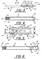
- FIG. 3 is a partially cut away side elevational view of the contaminant testing tube depicted in the abovementioned DE-A-3 810 534.
- FIG. 3a is a partially cut away side elevational view of an embodiment of the contaminant testing tube depicted in Fig. 2.
- FIGS. 3b through 3e are cross sectional views of additional alternate embodiments of the contaminant testing tube depicted in FIG. 2.
- FIG. 4 is a longitudinal sectional view of a tube container in the contaminant testing tube holder apparatus depicted in FIG. 2.
- FIG. 5 is an enlarged and exploded view in cross section of the flow restrictor in the contaminant testing tube holder apparatus in depicted FIG. 2.
- FIG. 6 is a longitudinal section view of a modified tube container.
- FIG. 7 is an exploded cross sectional view of a modified flow restrictor.
- FIG. 1 depicts the present invention being used in conjunction with a
compressor 10 of a refrigeration, air conditioning, or similar closed system incorporating a compressor.Compressor 10 has asuction line 12 containingservice valve 14 and adischarge line 16 containingservice valve 18. The figure illustrates the invention in use to test for the presence of contaminants in therefrigerant leaving compressor 10 viadischarge line 16. The present invention may be used to sample the refrigerant at other points in the system such assuction line 12. The present invention can be used to test refrigerants in both high and low pressure systems. Moreover, the present invention can be used to test for contaminants in other types of systems. In FIG. 1, as well as in FIGS. 2 through 4, arrow A denotes the direction of refrigerant sample flow during a test. - FIG. 3 depicts a
contaminant testing tube 20 for detecting the presence of water and inorganic acid contaminants in a refrigerant according to DE-A-3 810 534. -
Testing tube 20 is a generallycylindrical tube 22 made of a suitable transparent material such as glass.Tube 22 has two oppositely disposed tapered ends terminating respectively infrangible inlet tip 24 andfrangible outlet tip 26.Tips open inlet end 28 and open outlet end 30 (FIG. 2).Testing tube 20 is divided intodemister section 32, for oil separation, andcontaminant indicating section 34.Tube 22 can be 130 mm in overall length and 105 mm in length excluding the tapers at the tips, and the inside and outside diameters oftube 22 can be 4 mm and 6 mm respectively. In the assembledtube 20,demister section 32 extends frominlet end 24 for about half the length oftube 22. Its function is to separate entrained oil from the refrigerant before the refrigerant reachescontaminant indicating section 34 as will be fully described below. - From the inlet end of
contaminant indicating section 34 and proceeding in the direction of sample flow (arrow A),tube 22 contains a 3 mm length ofbrass screen 36, a 1 mm thickglass fiber disk 37, a 12 mm long water removal andindicator section 39, a 1 mm thickglass fiber disk 40, an 8 mm length of rolledbrass screen 42, a 1 mm thickglass fiber disk 43, a 25 mm longacid indicator section 45 and a 3 mm length ofbrass screen 46. The chemical indicator media contained in water removal andindicator section 39 and inacid indicator section 45 are located intube 22 relative tomarkings markings tube 22 aftertube 22 is sealed. In addition to glass fiber,partitioning disks Partitioning disks tube 22 and the like. The primary function of screen orfilter members sections disks contaminant indicating section 34 as well as providing, in the case ofscreen 42, physical separation for the chemicals. Screen orfilter members indicator sections indicator sections filter members - Disposed on the outer surface of
contaminant indicating section 34 are a series of scale orreference markings respective indicator sections markings tube 22, the granularity of the indicating medium and the like.Markings tube 22 by means of an adhesive, etching or the like. - Alternatively,
markings 39a and/or 45a can be eliminated and the contaminant concentration determined by color change of anentire indicator section - If they come in contact, there can be interactions between the water removal and indicating medium and the acid indicating medium resulting in color changes not representative of the presence of water or acid in the refrigerant sample.
Glass fiber disk 40, rolledbrass screen 42 andglass fiber disk 43 serve to separate the indicating media. The respective media can also react with moisture and other constituents of ambient air.Frangible tips testing tube 20 from the external environment until the tips are broken off just prior to use. - As noted above, lubricating oil is usually added to the refrigerant in a refrigeration, air conditioning or similar system and circulates with the refrigerant through the system. A sample drawn from the system will therefore also contain a small amount of oil. If oil in the sample flow comes in contact with any of the indicating media, it could cause false or inaccurate indications of the presence of a contaminant. It is therefore desirable to separate any entrained oil from the refrigerant sample flow.
- Referring to FIGS. 2 and 3, separation of entrained oil from the refrigerant is accomplished by means of
demister section 32 oftesting tube 20 acting in conjunction withflow restrictor 48. The pressure of the refrigerant sample is reduced from system pressure to a pressure near ambient as the refrigerant passes throughrestrictor 48 and before it enters testingtube 20 throughopen inlet end 28. Because of the pressure decrease, entrained oil vapors separate from the refrigerant and collect on the side ofdemister section 32 as minute droplets. The length ofdemister section 32 can vary depending upon the system pressure, the dimensions oftube 22, the anticipated amount of oil entrained in the vapor and the like. - FIGS. 1 and 2 depict contaminant testing
tube holder apparatus 50 adapted to contain eithertesting tube 20 of the prior art, ortesting tube 220 of the invention. Testingtube holder apparatus 50 comprisestube container 52,flow restrictor 48 andfluid hose 54, which may be a standard refrigerant hose.Fluid hose 54 includeshose line 56 having on oneend connector 58, typically a Schraeder type fitting, for connection to servicevalve 18 andconnector 60 at the other end for connecting to flowrestrictor 48. -
Tube container 52, depicted in FIG. 4, is made of a suitable transparent material, such as a polycarbonate or acrylic plastic, and has an inside diameter sized to containtesting tube 220, as illustrated in FIGS. 1 and 2.Tube container 52 includes oppositely disposedopen inlet end 62 andopen outlet end 64.Support member 66, located atopen outlet end 64, includes continuousbeveled surface 68 sloping radially inward and axially outward for centrally supporting conicalopen inlet end 30 oftesting tube 220. Other means of support can be used to centrally locate open outlet end 230 intube container 52.Open inlet end 62 has an internally threadedsurface portion 70 for connection to flowrestrictor 48. - FIG. 5 depicts
flow restrictor 48, an elongated body having oppositely disposedend sections End section 72 includes a threadedsurface 76 for attachingflow restrictor 48 toconnector 60 offluid hose 54 and pressure reducing means 78 disposed just inward ofopening 80.Pressure reducing means 78 includescollar section 82 spaced axially and radially inward of opening 80 to defineannular space 84 betweeninner surface 86 and the outer surface ofcollar section 82.Collar section 82 also defines annularbottom surface 88, annularremote end surface 90 andpassage 92.Pressure reducing means 78 further compriseswall member 94 at the innermost end ofpassage 92 within which is disposedsmall orifice 96. In this embodiment, the diameter oforifice 96 is sized to provide a refrigerant vapor flow of about 300 cc/min when operating at a refrigerant pressure of about 900 kPa. Withinpassage 92 is continuousbeveled surface 98 sloping radially inward and axially inward towardswall member 94 and defining the entrance toorifice 96.Pressure reducing means 78 can be configured to produce greater or lesser flows or to produce the same flow at higher or lower refrigerant pressures. -
End section 74 includes externally threadedsurface 100 for attachingflow restrictor 48 to threadedsurface portion 70 oftube container 52.End section 74 further includesopening 102,annular groove 104 andpassage 106 in fluid communication withpassage 92 throughorifice 96. The outer surface ofend section 74 also includeshex nut flange 108 to assist in manually connectingflow restrictor 48 tofluid hose 54 andtube container 52. As illustrated,passage 106 is larger in diameter thanpassage 92. - A vapor permeable screen or filter 110 is disposed in opening 80 of
end section 72 and rests against annularremote end surface 90 ofcollar section 82. On the opposite end offlow restrictor 48, a seal, such as O-ring 112, is fitted inannular groove 104 to provide a fluid tight fit betweenflow restrictor 48 and open inlet end 228 oftesting tube 220 so that all of the refrigerant sample flow passes throughtube 220. Screen or filter 110 filters particulate matter out of the refrigerant sample flow not intended to be detected in indicator sections 239 and 245 oftesting tube 220 and prevents clogging oforifice 96. - Alternatively, flow
restrictor 48 orpressure reducing means 78 could be disposed inconnector 58 ofhose line 56 to provide the desired refrigerant sample flow rate throughline 56 andtube 220 or pressure reducing means 78 can be disposed atopen inlet end 64 oftube container 52. - FIG. 7 depicts a modified flow restrictor 150 which may be used in place of flow restrictor 48 (Fig. 5). Flow restrictor assembly 150 includes
orifice holder 160,retainer 170,cap 180 and O-rings Orifice holder 160 has bore 162 which includes threadedsection 164 terminating in annularrelieved portion 166.Threads 168 are formed on the exterior oforifice holder 160 and correspond tothreads 76 of flow restrictor 48 (FIG. 5).Threads 168 serve to permit connection oforifice holder 160 toconnector 60.Orifice retainer 170 hasfirst bore 172 and threaded second bore 174 withshoulder 173 between the two bores. Threadedportion 176 is formed on the exterior oforifice retainer 170 and terminates atshoulder 177. Threadedsection 164 and threadedportion 176 can be threaded together so as to force O-ring 190 intorelieved portion 166 to form a seal betweenorifice holder 160 andorifice retainer 170.Orifice 178, containingpassage 179, is pressed intobore 172.Passage 179 can be selected to provide a desired flow rate.Cap 180 has bore 182 extending through it together with first threadedportion 184, second threaded portion 188 andhex nut flange 186 withannular recess 185. Secondannular recess 189 is formed in the downstream end ofhex nut flange 186. First threadedportion 184 is received in threadedsecond bore 174 and forces O-ring 192 intorecess 185 to form a seal betweenorifice retainer 170 andcap 180. Second threaded portion 188 corresponds to externally threadedsurface 100 and is engagable with threadedsurface portion 70 oftube container 52. O-ring 194, in conjunction withrecess 189 and conically shaped upstream open end 228 oftesting tube 220, forms a seal so that all of the refrigerant flows throughbore 182 into testing tube 220 (FIG. 2). A filter (not illustrated) such as screen 110 (FIG. 5) may be located at any suitable location upstream oforifice 178. - FIG. 6 depicts
tube container 52 modified to include flow indicator 114 at downstreamopen end 64. Flow indicator 114 indicates that a proper refrigerant sample flow rate exists to ensure accurate indication of the contaminants being tested for. Flow indicator 114 compriseschamber 116, which can be integral withtube container 52 or made separately and then attached totube container 52 by any suitable means and an indicator element such aspith ball 118 orflow line 122 disposed inchamber 116. - In operation, after connection to
compressor 10,tube container 52 is held vertically so that flow indicator 114 is above the container. If an adequate sample flow rate exists, it will causeball 118 to be urged upwardly to flowline 122. Ifball 118 does not reachline 122, then the sample flow rate is less than desirable. Inadequate sample flow rate can indicate a blockage in the system, the testing apparatus or the like. -
Ball 118 has a diameter greater than that ofopen end 64 andopening 120 and can be made of any suitable lightweight material. Further, flow indicator 114 can be a separate device which can be used by manually holding it in place, engagingopen end 64 oftube container 52 and directing all of the sample flow passing throughopen end 64 through the flow indicator. - Other means for indicating flow rate, such as a thin filament can be used. At a predetermined, acceptable flow rate, the filament can be designed to be parallel to the general direction of sample flow. Any nonparallel position of the filament indicates a less than desirable flow rate.
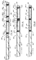
Discharge opening 120 may also be configured so that it produces an audible indication (e.g., a whistling sound) that there is sample flow or so that a bladder-like device (e.g. a balloon) can be fitted over it to indicate sample flow by inflation. - FIGS. 3a through 3d depict several alternate testing tube embodiments of the invention. Each is generally similar in configuration and dimensions to
testing tube 20 of DE-A-3 810 534 (FIG. 3), so as to enable any of the embodiments to be used with testing tube holder apparatus 50 (FIGS. 1,2,4, and 5). The configuration and dimensions ofapparatus 50 may also be modified to accommodate a testing tube of a different size or construction. The various embodiments share several features and characteristics in common. - In FIG. 3a,
testing tube 220 comprisestube 222 made of a suitable material, such as glass, and havingfrangible inlet end 224 andfrangible outlet end 226, ends 224 and 226 being tapered.Testing tube 220 is divided intodemister section 232 andcontaminant indicating section 234.Contaminant indicating section 234 containsmembrane 241,support disk 242, water indicator and removal section 239 containing an appropriate removal and indicating medium,membrane 243, support disk 244, acid indicator section 245 containing an appropriate indicating medium,membrane 246 andsupport disk 247. -
Testing tube 320 is depicted in FIG. 3b in an exploded view as it might appear just prior to final assembly of its various sections.Tube 320 is divided intodemister section 332 andcontaminant indicating section 334.Contaminant indicating section 334 comprises water removal andindicator subsection 351 andacid indicator subsection 352. During final assembly of the sections, male outlet end 335-1, having passage 331-1, ofdemister section 332 is fitted to female inlet end 336-1 of water indicator andremoval subsection 351 and similarly, male outlet end 335-2, having passage 331-2, of water indicator andremoval subsection 351 is fitted to female inlet end 336-2 ofacid indicator subsection 352, thus forming a single tubular member.Section 332 andsubsections acid indicator section 352 under the urging of the refrigerant sample flow by any suitable means such as being a press (friction) fit withsection 352, being fixed by adhesive or chemical welding, or by the addition of a circumferential shoulder tosection 352 similar toshoulder 454 depicted in FIG. 3c. When assembled,contaminant indicating section 334 oftesting tube 320 contains membrane 341-1, support disk 342-1, water indicating andremoval medium 339, membrane 341-2, support disk 342-2, membrane 341-3, support disk 342-3, acid indicating medium 345, membrane 341-4 and support disk 342-4. -
Testing tube 420, depicted in FIG. 3c, comprisestube barrel 422 within which are slideably fitted tubularwater removal cartridge 451 andacid indicator cartridge 452. The respective inner and outer diameters oftube barrel 422 andcartridges tube 422 must pass through, and not bypass,cartridges cartridge 451 upstream of membrane 441-1.Cartridges outlet end 426 oftube barrel 422 under the urging of the refrigerant sample flow by a suitable stopping means such ascircumferential shoulder 454. The dimensions oftube barrel 422 and the placement ofcartridges demister section 432 is formed just insideinlet end 424.Water removal cartridge 451 contains an appropriate removal medium 439, membranes 441-1 and 441-2 and support disks 442-1 and 442-2.Acid indicator cartridge 452 contains an appropriate indicating medium 445, membranes 441-3 and 441-4 and support disks 442-3 and 442-4. -
Testing tube 520, depicted in FIG. 3d, comprisestube barrel 522 within which are contained water indicator andremoval capsule 551, containing an appropriate water indicating andremoval medium 539, andacid indicator capsule 552, containing an appropriate acid indicating medium 545. Support disk 542-1 is located betweeninlet end 524 and water indicating andremoval capsule 551, support disk 542-2 is located betweencapsules acid indicating capsule 552 andoutlet end 526. The support disks and capsules are prevented from sliding out oftube 522 throughoutlet end 526 under the urging of the refrigerant flow by an appropriate stopping means such ascircumferential shoulder 554. The dimensions oftube 522 and the placement ofcapsules demister section 532 is formed just insideinlet end 524.Capsules media tube 522 so that all the refrigerant enteringtube 522 must pass through, and cannot bypass,capsules -
Membranes capsules 551 and 552 (FIG. 3d) are gas and vapor impermeable and can be made of any suitable material such as vinylidine chloride film (e.g. Dow Saran Wrap) which will isolate the various indicating media from each other and from the external environment under static unpressurized conditions but will rupture when subjected to a relatively high differential pressure across the film. Such a differential pressure is created when sample refrigerant is first introduced into testing tube 220 (FIG. 3a) or the testing tubes in the other embodiments, i.e. testing tube 320 (FIG. 3b), 420 (FIG. 3c) or 520 (FIG. 3d).Support disks 242, 244 and 247 (FIG. 3a), support disks 342-1, 342-2, 342-3 and 342-4 (FIG. 3b), support disks 442-1, 442-2, 442-3 and 442-4 (FIG. 3c), and support disks 542-1, 542-2 and 542-3 (FIG. 3d) can be made of any suitable material, (e.g. a perforated plastic) that will provide physical support to the various membranes and yet is permeable to allow a refrigerant sample flow when the membranes rupture. The sand bases, described below, of the removal and indicating media contained incapsules testing tube 520. The various testing tube embodiments may contain other means to burst or pierce the various isolation membranes at the commencement of a test. - Testing tube 220 (FIG. 3a) has two means to isolate the indicating media from the external environment before commencement of a test:
membranes - All of the testing tubes depicted in FIGS. 3a through 3d can have their respective tubular members made of glass, but a suitable transparent, rigid plastic such as cellulose butyrate, is more appropriate for making the tubular members of the embodiments depicted in FIGS. 3b through 3d. If the tubular members are made of plastic, then the need for the protection of
tube container 52 is obviated. Thentube container 52 can be eliminated from testingtube apparatus 50, the inlet ends, e.g. end 324 (FIG. 3b) of the testing tubes can be configured so as to attach directly to flow restrictor 48 (FIGS. 2 and 5) or modified flow restrictor 150 (FIG. 7) and, if desired, the outlet ends, e.g. end 326 (FIG. 3b) of the testing tubes can be configured to contain a sample flow indicator device. These features are discussed in detail in the description of testing tube 620 (FIG. 3e) below. - The testing tube embodiments depicted in FIG. 3a through 3e may have markings disposed on the outer surfaces of their contaminant indicating sections in the same manner that
markings - The above discussions of the various embodiments of the testing tube of the invention have, for simplicity and clarity, described tubes containing only two contaminant removal and/or indicating sections, one for the removal as well as indication of water and one for the indication of acid. In addition, the present invention encompasses other features. The testing tube depicted in FIG. 3e illustrates several of these additional features.
- The testing tubes may be configured to have one or more indicator sections in addition to or in place of the indicator sections described above so that the apparatus can test for the presence of other refrigerant contaminants, including volatile organic acids, carbon dioxide, carbon monoxide, hydrogen and oxygen, thus providing a full range of tests to assist in analyzing the condition of both the refrigerant and the entire system. Testing tube 620 (FIG. 3e) is such a tube.
Testing tube 620 is similar in design and construction to testing tube 420 (FIG. 3c), having tubular contaminant removal and/or indicator cartridges slideably fitted into a tube barrel, buttesting tube 620 contains an additional indicator cartridge for testing a refrigerant sample for another contaminant.Testing tube 620 has other components that allow its connection directly to flow restrictor 48 (FIGS. 2 and 5) or modified flow restrictor 150 (FIG. 7) and that provide indication of refrigerant sample flow, thus eliminating the need for the use of tube holder 52 (FIGS. 2 and 4) or modifiedtube holder 52 with flow indicator 114 (FIG. 6). - Describing
testing tube 620 in detail, it comprisestube barrel 622 having threadedinlet portion 670 at itsopen inlet end 624 for attachingtesting tube 620 directly to flow restrictor 48 (FIGS. 2 and 5) or modified flow restrictor 150 (FIG. 7). Slideably fitted withintube barrel 622 are a plurality ofcartridges media tube barrel 622 andcartridges tube barrel 622 must pass throughcartridges tube barrel 622 and the placement of the cartridges within it are such that, when assembled,demister section 632 is formed upstream of the cartridges. The tubular members oftesting tube 620 can be made of a suitable rigid, transparent plastic.Media cartridge 651 should contain a medium that at least removes water from the sample flow, with the other cartridges and media being selected on the basis of the specific contaminants for which the testing tube will be used to test.Testing tube 620 is adaptable to factory assembly in a configuration having any number of cartridges to remove water and test for any number and combination of contaminants. The tube is also adaptable to assembly in the field by supplyingtube barrel 622 and a selection of cartridges containing a selection of media. A test technician can then make an on-site determination of the specific contaminants for which to test and assemble a testing tube that contains only those cartridges that contain media appropriate to the desired test. The construction ofindividual cartridges Testing tube 620 also has optionalflow indicator section 614 contained within the tube just insideoutlet end 626. Similar to flow indicator 114 (FIG. 6),flow indicator section 614 compriseschamber 616,passage 664 andoutlet 612.Chamber 616 may contain a flow indicator element such asball 618 to provide a visual indication of sample flow oroutlet 612 may be configured to produce an audible indication of flow. Note that a testing tube similar in construction to testing tubes 220 (FIG. 3a), 320 (FIG. 3b), 420 (FIG. 3c) or 520 (FIG. 3d) could also be made with any number and combination of removal and/or indicating media in a manner similar to that described fortesting tube 620. Testing tubes similar totesting tube testing tube 620 that eliminate the need for a tube holder and/or separate flow indicator. And testing tubes similar totesting tubes - Since most chemicals that are appropriate for use in the various indicating media are sensitive to water and thus could give false indications of the various contaminants if water is present in the refrigerant sample flow, it is advisable to include a section that at least removes water, but does not necessarily indicate its presence or concentration, in any testing tube of any configuration made or assembled according to the teaching of the present invention. This water removal section or subsection should be placed in the testing tube so that the refrigerant sample flows through it before reaching any of the other indicator sections that may be incorporated into a particular testing tube.
- The water removal medium can be any suitable substance that absorbs water vapor. If the medium is also to serve as an indicator, it should also undergo a visible change (e.g. in color) in the presence of water. An excellent choice for a combined water removal and indicating medium is cobaltous chloride, as that chemical absorbs water and turns from blue to pink when exposed to moisture. A suitable cobaltous chloride medium may be prepared by applying two coats of that chemical dissolved in acetone to a sand support base. Two chloroform washes then remove any excess chemical that might later flake from the sand particles.
- The acid indicating medium can be any suitable substance that undergoes a visible change in the presence of an inorganic acid having a pH of 3.2 to 4.2. A substance suitable for detecting such acids can be prepared by coating a silica sand base with a stock solution of bromophenol blue in a glycerol film. This chemical changes color from blue to yellow in the presence of such acids.
- A medium suitable for indicating volatile organic acids contaminants, in the pH range of 6.2 to 7.0, can be prepared using phenol red, which undergoes a color change from pink to yellow in the presence of such acids. Such a medium can be prepared by dissolving the indicating chemical in a solvent, washing a sand base in the solution and evaporating the solvent. If both a strong and a weak (organic) acid indicator section are incorporated in the same testing tube, the weak acid indicator section should be placed downstream in the refrigerant sample flow from the strong acid indicator.
- An indicating medium suitable for detecting carbon dioxide entrained in the refrigerant sample flow can be prepared from hydrazine and crystal violet, which changes color from white to violet in the presence of carbon dioxide. Such a medium can be prepared by dissolving the indicating chemical in a suitable solvent, washing a sand base in the solution and evaporating the solvent.
- A medium suitable for indicating the presence of carbon monoxide can be prepared using iodine pentoxide. That compound changes color from white to black when exposed to carbon monoxide. The carbon monoxide indicating medium can be prepared by dissolving the indicating chemical in a suitable solvent, washing a sand base in the solution and evaporating the solvent.
- The presence of hydrogen in the refrigerant sample flow can be indicated by a medium prepared from ammonium molybdate by dissolving that chemical in a suitable solvent, washing a sand base in the solution and evaporating the solvent. Ammonium molybdate changes from yellow to brown in color when exposed to hydrogen.
- A suitable medium for indicating the presence of oxygen can be prepared from titanium tetrachloride, which changes color from black to white in the presence of oxygen. Such a medium can be prepared by dissolving the indicating chemical in a suitable solvent, washing a sand base in the solution and evaporating the solvent. If this indicating medium is used in a testing tube, it should be placed downstream of the acid indicating sections in the refrigerant sample flow, as it can emit hydrogen chloride gas which would give false acid indications in the acid indicating sections.
- The below describes the procedure for testing for refrigerant contamination using the method and apparatus of the present invention employing testing tube 220 (FIG. 3a).
- Before conducting a test, the entire test apparatus should be purged. At a minimum, hose line 56 (FIG. 1) must be purged. Referring to FIGS. 1 and 2, the test apparatus is assembled for purging by engaging
flow restrictor 48, fitted withscreen 110 and O-ring 112, at threadedend section 74 to threadedsurface portion 70 oftube container 52. Flow restrictor 48 is then hand tightened totube container 52. Then threadedend section 72 offlow restrictor 48 is connected to threadedconnector 60 ofhose line 56. A purge flow is established by connectinghose line 56 to the system at suctionline service valve 18 by means ofSchraeder connector 58. Purging the test apparatus requires only a small flow of refrigerant before terminating the flow by removingSchraeder connector 58 from suctionline service valve 18. Note thathose line 54 is an optional accessory that may be used for convenience in the conduct of a test.Hose line 54 may be eliminated and flowrestrictor 48, provided with suitable fittings atend section 72, connected directly to suctionline service valve 18. - After the test apparatus is purged and
connector 58 is removed fromvalve 18, atesting tube 220 having the desired chemical indicating media in indicator sections 239 and 245 is prepared by breaking offfrangible tips Testing tube 220 is then inserted intotube container 52 so that open outlet end 230 is supported bybeveled surface 68 ofsupport member 66. Flow restrictor 48, still filled withscreen 110 and O-ring 112, is engaged at threadedend section 74 to threadedsurface portion 70 oftube container 52. Open inlet end 228 oftesting tube 220 should be received within O-ring 112 to make a gas tight fit, thus preventing the refrigerant sample flow from bypassingtesting tube 220. Flow restrictor 48 is then hand tightened totube container 52. - The test is commenced by again connecting
hose line 56 to the system at suctionline service valve 18 by means ofSchraeder connector 58. For optimum oil removal efficiency,tube container 52, withtesting tube 220 inserted, should be held so that its longitudinal axis is maintained vertical and end 228 is below end 230 throughout the test. - With the apparatus connected as described, the refrigerant sample, at system pressure, flows through
hose line 56 intoflow restrictor 48.Pressure reducing means 78 increases flow resistance and decreases sample flow rate thus reducing the pressure of the sample flow throughpressure reducing means 78. This reduction in pressure is accomplished initially bycollar section 82 andannular space 84, which reduce the area for the incoming flow. The sample flow continues throughpassage 92, which is reduced in cross section by continuously beveledsurface 98, andorifice 96. The sample flow that passes throughorifice 96 intopassage 106 thus is reduced from system pressure to an acceptable pressure (near ambient) and flow rate. The reduced pressure flow then passes throughopening 102 intotesting tube 220 through inlet end 228 through the breachable films (241, 243, 246) and out through outlet end 230. - Because of the rapid reduction in pressure of the refrigerant as it passes through
orifice 96 intodemister section 232, oil entrained in the sample will separate from the refrigerant and collect along the inner surface ofdemister section 232 as minute droplets. The sample flow and entrained contaminants then continue in the direction of arrow A throughmembrane 241,disk 242, water removal and moisture indicating section 239,membrane 243, disk 244, acid indicating section 245,membrane 246 and out outlet end 230. - After a prescribed testing time, ordinarily not more than ten minutes,
Schraeder connector 58 is disconnected from suctionline service valve 18 andtesting tube 220 is immediately withdrawn fromtube container 52. Any water or acid contaminants in the refrigerant vapor will be indicated by visible changes in the indicating media contained in indicator sections 239 and 245, respectively. - After test completion,
hose line 56 and flowrestrictor 48 is purged for subsequent tests. Ifhose line 56 and flow restrictor 48 are made of a disposable material, such as a suitable plastic, they can be discarded and replaced with anew hose line 56 and anew flow restrictor 48. - The acid indicating medium in acid indicator section 245 will change from blue to yellow in the presence of strong acids. The color change will extend through the medium from
membrane 243 in the direction of arrow A as a function of the acid concentration in the sample. The marks can be used to determine the length of the color change. The length of the color change is then entered into Table I. For example, if the acid changes the bromophenol blue to yellow a distance equal to four markings, then Table I is entered under the column designated marker No. atnumber 4 and then read across under the column indicating the testing time. If the flow was maintained for three minutes, then Table I would indicate an acid contamination of 0.20 parts per million. Similar tables can be empirically determined for water and other contaminants. - Table II illustrates another method of determining the amount or concentration of a contaminant, in this case water. Here the refrigerant sample is allowed to flow through
testing tube 220 until the color of the indicating medium turns the same shade as that on a colored card (not shown). When the two colors match, the time required for the color change is entered into Table II. Should it take three minutes for the indicating medium to turn the same shade as on the colored card, then that would indicate a contamination level of approximately 270 parts per million.TABLE I ACIDS APPROXIMATE PPM MARKER NUMBER SAMPLING TIME 1 MIN. 3 MIN. 5 MIN. 10 MIN. 1 0.2 0.06 0.04 0.02 2 0.3 0.10 0.06 0.03 3 0.4 0.13 0.08 0.04 4 0.5 0.20 0.11 0.05 5 0.6 0.21 0.13 0.06 6 0.8 0.26 0.15 0.08 TABLE II WATER VAPOR 1 MINUTE INDICATES ABOUT 800 PPM 3 MINUTES INDICATES ABOUT 270 PPM 5 MINUTES INDICATES ABOUT 160 PPM 10 MINUTES INDICATES ABOUT 80 PPM - The procedure using other embodiments of the testing tube (FIGS. 3b through 3e) with additional indicating media for the indication of other refrigerant contaminants is similar to that described above except that, depending on tube configuration,
tube holder 52 may not be used. - When a testing tube containing isolation membranes, e.g. membrane 341-1 (FIG. 3b), or capsules, e.g capsule 551 (FIG. 3d), is used, upon connection of
hose line 56 to the system, pressure will build up in the testing tube upstream of the membrane or the upstream end of the capsule until the differential pressure across the membrane or capsule end is sufficient to break the membrane or capsule end. Then pressure will build up in the next section of the tube until the next membrane or capsule end is breached and so on until all membrane or capsule ends are breached and sample flow is established through the entire testing tube. This sequence is rapid and usually imperceptible to the ordinary observer. - In summary, to test a refrigeration, air conditioning or similar closed system for the presence of water or other contaminants using testing tube 220 (FIG. 3a), a sample flow of refrigerant is taken from the system and passed at near atmospheric pressure into a testing tube. In the demister section of the tube any entrained oil is removed. The refrigerant and contaminants then pass through a screen and a disk into a water removal section. In this section, any water present is removed. This section may also be an indicator and produce a color change in an indicating medium whose distance of propagation through the medium is a measure of the water concentration. The removal of the water results in any remaining contaminants being present as anhydrous gases. The refrigerant and any remaining contaminants then pass through a disk, a screen and another disk before reaching an acid indicating section. The water and acid indicating sections are separated because the two indicating media could interreact causing false contaminant concentration indications. The acids react with the acid indicating medium producing a color change whose distance of propagation through the medium is a measure of the acid concentration. The presence and concentrations of other contaminants, i.e. volatile organic acids, carbon dioxide, carbon monoxide, hydrogen and oxygen may be determined by testing tubes containing suitable indicating media. The presence of excessive concentrations of excess water and other contaminants in the refrigerant indicates the need for replacing the refrigerant charge, adding conditioning agents to the refrigerant, or taking other corrective action.
- Detection of the presence of certain contaminants may also assist in assessing the condition of system components and in analyzing the cause of failures.
- Although several preferred embodiments of the present invention have been described and illustrated, other embodiments may occur to one skilled in the art. For example, the present invention may be used not only for testing refrigeration, air conditioning and similar systems but for testing other types of systems as well. In addition, the specification discloses specific indicating media for indicating the presence of specific contaminants. Other suitable indicating media may be substituted for those disclosed. And one skilled in the art may develop other methods of fabricating the testing tubes described. It is therefore intended that the present invention be limited only by the scope of the below claims.
Claims (14)
- A means for testing for contaminants in a refrigerant contained in a system comprising:a testing tube (220;320;420;520;620) comprising(a) a hollow tube (222;322;422;522;622),(b) means (232;332;432;532;632) disposed within said hollow tube for separating entrained oil from a sample flow of said refrigerant from said system,(c) means (239;351;451;551;651) disposed within said hollow tube for removing water contamination from said sample flow,(d) means (245;352;452;552;652;653) disposed within said hollow tube for indicating the presence and concentration of at least one contaminant in said sample flow,(e) separation means (224,226, 241, 243, 246;341;441;551, 552; 641) for separating said removing means and said indicating means one from another and from the environment external to said hollow tube until the commencement of said testing, and(f) means for breaching said separation means (224,226,241,243,246;341;441;551,552;641) upon commencing said testing, andrefrigerant pressure reducing and delivery means (48;150), in flow communication with said testing tube for directing said refrigerant flow at a reduced pressure from said system to said testing tube,characterized in that the separation means for isolating said removal and said indicating means one from another comprises breachable film means (241,243,246;341;441;551,552;641) disposed within said hollow tube, said film means (241,243,246;341;441;551,552;641) being impervious to gas and vapour and being breached at the commencement of said testing thus allowing said sample flow to come in contact with said removing and indicating means.
- The testing means of claim 1, characterized in that said testing means further comprises a tube container (52) for holding and supporting said testing tube.
- The testing means of claim 1, characterized in that said water contamination removal means (239;351;451;551;651) also indicates the presence and concentration of said water contamination in said sample flow.
- The testing means of claim 1, characterized in that said one or more other contaminant indicating means (245;352;452;552;652;653) comprises medium for indicating the presence and concentration of at least one of the following contaminants in said sample flow:(a) inorganic acids,(b) volatile organic acids,(c) oxygen,(d) hydrogen,(e) carbon dioxide, and(f) carbon monoxide.
- The testing means of claim 1, characterized in that said water contamination removal means further comprises water contamination presence and concentration indicating means (239;351;451;551;651) and said testing tube includes means (39a) for viewing said water contamination removal and indicating means from outside said testing tube.
- The testing means of claim 5, characterized in that said water contamination indicating and removal medium is cobaltous chloride.
- The testing means of claim 1, characterized in that said contaminant indicating means (245;352;452;552;652,653) indicate the presence and concentration of said contaminant and said testing tube includes means (45a) for viewing said indicating means from outside said testing tube.
- The testing means of claim 7, characterized in that said contaminant indicating media include at least one member of the group consisting of the following:(a) bromophenol blue in a glycerol film for indicating inorganic acids,(b) phenol red for indicating volatile organic acids,(c) titanium tetrachloride for indicating oxygen,(d) ammonium molybdate for indicating hydrogen,(e) hydrazine and crystal violet for indicating carbon dioxide, and(f) iodine pentoxide for indicating carbon monoxide.
- The testing means of claim 1, characterized in that said film isolating means comprises a breachable membrane (241,243,246;341;441;641).
- The testing means of claim 9, characterized in that differential pressure across said breachable membrane (241,243,246;341;441;551;552;641) breaches said breachable membrane, said differential pressure being created when said refrigerant enters said testing tube at the commencement of said testing.
- The testing means of claim 1, characterized in that said separating, removing and indicating means each comprise individual subsection (351,352) that are assembled to form said testing tube.
- The testing means of claim 1, characterized in that said removal and indicating means each comprise individual cartridges (651,652,653) that are inserted into said hollow tube to form, with said separating means (632), said testing tube.
- The testing means of claim 1, characterized in that said removal and indicating means each comprise individual capsules (551,552) inserted into said hollow tube to form, with said separating means (532), said testing tube.
- The testing means of claim 1, characterized in that said testing means further comprises refrigerant flow indicator means (114) in flow communication with said testing tube.
Applications Claiming Priority (2)
| Application Number | Priority Date | Filing Date | Title |
|---|---|---|---|
| US449679 | 1989-12-12 | ||
| US07/449,679 US5071768A (en) | 1985-06-14 | 1989-12-12 | Method and apparatus for refrigerant testing in a closed system |
Publications (3)
| Publication Number | Publication Date |
|---|---|
| EP0433211A2 EP0433211A2 (en) | 1991-06-19 |
| EP0433211A3 EP0433211A3 (en) | 1992-02-26 |
| EP0433211B1 true EP0433211B1 (en) | 1996-04-17 |
Family
ID=23785063
Family Applications (1)
| Application Number | Title | Priority Date | Filing Date |
|---|---|---|---|
| EP90630217A Expired - Lifetime EP0433211B1 (en) | 1989-12-12 | 1990-12-06 | Apparatus for refrigerant testing in a closed system |
Country Status (6)
| Country | Link |
|---|---|
| US (1) | US5071768A (en) |
| EP (1) | EP0433211B1 (en) |
| JP (1) | JP3029210B2 (en) |
| KR (1) | KR0153256B1 (en) |
| ES (1) | ES2087140T3 (en) |
| HK (1) | HK152696A (en) |
Families Citing this family (27)
| Publication number | Priority date | Publication date | Assignee | Title |
|---|---|---|---|---|
| DK167823B1 (en) * | 1991-06-18 | 1993-12-20 | Asger Gramkow | DEVICE FOR THE REGISTRATION OF MOISTURIZING AND CONDITION OF A refrigerant |
| US5538690A (en) * | 1991-10-21 | 1996-07-23 | Greer; Garry L. | Air quality indicator system for breathing air supplies |
| US5345774A (en) * | 1993-02-01 | 1994-09-13 | Carrier Corporation | Method and apparatus for zero emissions testing of a refrigerant in a closed system |
| US5372785A (en) * | 1993-09-01 | 1994-12-13 | International Business Machines Corporation | Solid-state multi-stage gas detector |
| US5363661A (en) * | 1993-09-03 | 1994-11-15 | Condit David A | Method and apparatus for testing refrigerant |
| US5377496A (en) * | 1993-10-05 | 1995-01-03 | Carrier Corporation | Refrigeration system with installed acid contamination indicator |
| US5351500A (en) * | 1993-12-03 | 1994-10-04 | Texas Medical Center Central Heating And Cooling Cooperative Association | Refrigerant leak detector system |
| US5419177A (en) * | 1994-03-25 | 1995-05-30 | Pastorello; John | Refrigerant gas contamination detector kit |
| US6514765B1 (en) | 1995-04-17 | 2003-02-04 | Mainstream Engineering Corporation | Acid test kit and method of use |
| US5846833A (en) * | 1997-01-17 | 1998-12-08 | Carrier Corporation | Method and apparatus for testing a non-hydrocarbon refrigerant |
| BR9700384A (en) | 1997-03-12 | 1998-12-08 | Brasil Compressores Sa | System and method for detecting antifreeze in airtight compressor |
| US5831144A (en) * | 1997-04-28 | 1998-11-03 | Pastorello; John | Refrigeration compressor oil testing process and apparatus |
| GB2324868B (en) * | 1997-05-01 | 2001-11-21 | Sun Electric Uk Ltd | Method and apparatus for matching refrigerants |
| JP3387369B2 (en) * | 1997-07-04 | 2003-03-17 | 松下電器産業株式会社 | Manufacturing method of air conditioner |
| JP3763559B2 (en) * | 1997-12-16 | 2006-04-05 | 松下電器産業株式会社 | Purge device |
| CN1153032C (en) * | 1998-06-11 | 2004-06-09 | 三洋电机株式会社 | Refrigerant regenerating device, refrigerant regenerating method, refrigerator having refrigerant regenerating device, control method for refrigerant circuit or recovery |
| EP1469262A3 (en) * | 1999-04-01 | 2005-04-20 | Matsushita Electric Industrial Co., Ltd. | Replacing gas collecting trap apparatus used for installing an air conditioner and installation method therefor |
| DE29908215U1 (en) * | 1999-05-07 | 1999-08-12 | Draeger Sicherheitstech Gmbh | Gas sampling device |
| US6576473B1 (en) * | 1999-05-28 | 2003-06-10 | Mainstream Engineering Corporation | Removable test kit and method of use for vapor compression systems |
| JP3704269B2 (en) * | 2000-02-14 | 2005-10-12 | ダイキン工業株式会社 | Refrigeration apparatus having oil deterioration judgment device |
| US6308523B1 (en) | 2000-03-20 | 2001-10-30 | Mainstream Engineering Corporation | Simplified subcooling or superheated indicator and method for air conditioning and other refrigeration systems |
| JP5800562B2 (en) * | 2011-05-10 | 2015-10-28 | 三菱電機株式会社 | Refrigeration air conditioner failure cause estimation method |
| US8779362B1 (en) | 2012-04-16 | 2014-07-15 | Ted J. Amundsen | Infrared acid detector and method |
| DE102013006548B4 (en) | 2013-04-16 | 2022-02-03 | Dräger Safety AG & Co. KGaA | Measuring device, reaction carrier and measuring method |
| DE202017105769U1 (en) | 2016-09-23 | 2017-12-21 | Trane International Inc. | System for detecting refrigerant gas contamination in an HVAC system |
| FR3095516B1 (en) * | 2019-04-25 | 2022-10-14 | Univ De Pau Et Des Pays De Ladour | Device for taking a sample of elements of interest present in trace amounts in a pressurized gas |
| US20230366814A1 (en) * | 2020-09-14 | 2023-11-16 | University Of Maine System Board Of Trustees | Systems and methods for determining water content in a sample |
Family Cites Families (17)
| Publication number | Priority date | Publication date | Assignee | Title |
|---|---|---|---|---|
| US3127249A (en) * | 1964-03-31 | Ammonium nitrate | ||
| US2429694A (en) * | 1944-03-29 | 1947-10-28 | Little Inc A | Method and equipment for indicating the water content of a gas |
| US3539302A (en) * | 1968-04-10 | 1970-11-10 | Hays Corp | Apparatus for rapid analysis of trace gas |
| US3625656A (en) * | 1969-03-28 | 1971-12-07 | John K Paulson | Gas leak detector for liquid-cooled internal combustion engines |
| DE2421860C3 (en) * | 1974-05-06 | 1980-01-03 | Nikolai Gavrilovitsch Afanasiev | Sensing element of a photocolorimetric gas analyzer, method for producing the sensing element and photocolorimetric gas analyzer with the sensing element |
| US4018061A (en) * | 1974-11-27 | 1977-04-19 | General Motors Corporation | Moisture indicator |
| DE2512687C3 (en) * | 1975-03-20 | 1979-10-11 | Auergesellschaft Gmbh, 1000 Berlin | Detector tube |
| GB1582376A (en) * | 1976-04-17 | 1981-01-07 | Compur Electronic Gmbh | Method for measuring the concentration of gaseous oxygen or carbon dioxide in gaseous or liquid samples in particular in breath and blood samples |
| DE2854421B1 (en) * | 1978-12-16 | 1980-03-27 | Draegerwerk Ag | Test tube for the quantitative determination of aerosol-like metal cyanides |
| DE2855648C2 (en) * | 1978-12-22 | 1981-04-30 | Drägerwerk AG, 2400 Lübeck | Detector tubes for measuring sodium hydroxide and / or calcium oxide aerosols |
| DE2942674B1 (en) * | 1979-10-23 | 1981-05-07 | Drägerwerk AG, 2400 Lübeck | Test tube for measuring nickel aerosols |
| DE2942673B1 (en) * | 1979-10-23 | 1981-05-07 | Drägerwerk AG, 2400 Lübeck | Test tube for measuring copper aerosols |
| DE2948218C2 (en) * | 1979-11-30 | 1982-06-09 | Drägerwerk AG, 2400 Lübeck | Test tube for the quantitative determination of sulfuric acid aerosols |
| US4389372A (en) * | 1981-07-13 | 1983-06-21 | Lalin Hill S | Portable holder assembly for gas detection tube |
| DE3223742C2 (en) * | 1982-06-25 | 1985-08-22 | Drägerwerk AG, 2400 Lübeck | Detector tubes for the selective measurement of oil mist |
| US4923806A (en) * | 1985-06-14 | 1990-05-08 | Carrier Corporation | Method and apparatus for refrigerant testing in a closed system |
| US4866994A (en) * | 1988-07-18 | 1989-09-19 | General Motors Corporation | Refrigeration system oil measurement and sampling device |
-
1989
- 1989-12-12 US US07/449,679 patent/US5071768A/en not_active Expired - Lifetime
-
1990
- 1990-12-06 ES ES90630217T patent/ES2087140T3/en not_active Expired - Lifetime
- 1990-12-06 EP EP90630217A patent/EP0433211B1/en not_active Expired - Lifetime
- 1990-12-11 KR KR1019900020312A patent/KR0153256B1/en not_active IP Right Cessation
- 1990-12-12 JP JP2410181A patent/JP3029210B2/en not_active Expired - Lifetime
-
1996
- 1996-08-08 HK HK152696A patent/HK152696A/en not_active IP Right Cessation
Also Published As
| Publication number | Publication date |
|---|---|
| JPH0466837A (en) | 1992-03-03 |
| EP0433211A2 (en) | 1991-06-19 |
| KR910012694A (en) | 1991-08-08 |
| JP3029210B2 (en) | 2000-04-04 |
| ES2087140T3 (en) | 1996-07-16 |
| EP0433211A3 (en) | 1992-02-26 |
| US5071768A (en) | 1991-12-10 |
| KR0153256B1 (en) | 1998-12-01 |
| HK152696A (en) | 1996-08-16 |
Similar Documents
| Publication | Publication Date | Title |
|---|---|---|
| EP0433211B1 (en) | Apparatus for refrigerant testing in a closed system | |
| US4923806A (en) | Method and apparatus for refrigerant testing in a closed system | |
| EP1238253B1 (en) | Method for detecting and localising leaks and suitable devices for carrying out said method | |
| US7399346B2 (en) | Quick-change filter system and a base and a quick-change filter intended for such a system | |
| CA1165250A (en) | Method and apparatus for testing and using membrane filters in an on site of use housing | |
| US7516665B2 (en) | Double membrane transducer protector | |
| CN105339773B (en) | It can the sampler that thickly seals of fluid tight | |
| US4786298A (en) | Filter assembly | |
| US6889537B2 (en) | Method of refrigerant leak sealant additive detection | |
| US5659130A (en) | Simple device for testing chemical permeation | |
| US4803843A (en) | Low pressure refrigerant contaminant tester | |
| US5727498A (en) | Retractable visual indicator assembly | |
| US5363661A (en) | Method and apparatus for testing refrigerant | |
| US4976867A (en) | Systems and methods for predetermining maximum pressure differentials for microporous hollow fibers employed in liquid-liquid extractions | |
| US5174964A (en) | Gas testing apparatus | |
| US11268541B2 (en) | Pressure accumulator having a monitoring device | |
| JP2022045896A (en) | Method for testing integrity of filter medium | |
| WO2000004981A1 (en) | Filter assemblies | |
| US20220047825A1 (en) | A flow indicator for oxygen addition to rebreathing systems | |
| JP3139969B2 (en) | Sight glass leak detector | |
| Hackler et al. | Retractable Visual Indicator Assembly | |
| WO1990002598A1 (en) | Filter assembly | |
| SU1749826A1 (en) | Device for entry of sample to chromatograph | |
| GB2278681A (en) | Contamination indicator for use in liquids or gases | |
| CA1171363A (en) | Filter cartridge with microporous membrane filter media for mounting in a filter housing |
Legal Events
| Date | Code | Title | Description |
|---|---|---|---|
| PUAI | Public reference made under article 153(3) epc to a published international application that has entered the european phase |
Free format text: ORIGINAL CODE: 0009012 |
|
| AK | Designated contracting states |
Kind code of ref document: A2 Designated state(s): ES GB IT |
|
| PUAL | Search report despatched |
Free format text: ORIGINAL CODE: 0009013 |
|
| AK | Designated contracting states |
Kind code of ref document: A3 Designated state(s): ES GB IT |
|
| 17P | Request for examination filed |
Effective date: 19920729 |
|
| 17Q | First examination report despatched |
Effective date: 19940204 |
|
| GRAA | (expected) grant |
Free format text: ORIGINAL CODE: 0009210 |
|
| AK | Designated contracting states |
Kind code of ref document: B1 Designated state(s): ES GB IT |
|
| REG | Reference to a national code |
Ref country code: ES Ref legal event code: BA2A Ref document number: 2087140 Country of ref document: ES Kind code of ref document: T3 |
|
| ITF | It: translation for a ep patent filed |
Owner name: UFFICIO BREVETTI RICCARDI & C. |
|
| REG | Reference to a national code |
Ref country code: ES Ref legal event code: FG2A Ref document number: 2087140 Country of ref document: ES Kind code of ref document: T3 |
|
| GRAH | Despatch of communication of intention to grant a patent |
Free format text: ORIGINAL CODE: EPIDOS IGRA |
|
| PLBE | No opposition filed within time limit |
Free format text: ORIGINAL CODE: 0009261 |
|
| STAA | Information on the status of an ep patent application or granted ep patent |
Free format text: STATUS: NO OPPOSITION FILED WITHIN TIME LIMIT |
|
| 26N | No opposition filed | ||
| REG | Reference to a national code |
Ref country code: GB Ref legal event code: IF02 |
|
| PGFP | Annual fee paid to national office [announced via postgrant information from national office to epo] |
Ref country code: GB Payment date: 20061106 Year of fee payment: 17 |
|
| PGFP | Annual fee paid to national office [announced via postgrant information from national office to epo] |
Ref country code: ES Payment date: 20061214 Year of fee payment: 17 |
|
| PGFP | Annual fee paid to national office [announced via postgrant information from national office to epo] |
Ref country code: IT Payment date: 20061231 Year of fee payment: 17 |
|
| GBPC | Gb: european patent ceased through non-payment of renewal fee |
Effective date: 20071206 |
|
| PG25 | Lapsed in a contracting state [announced via postgrant information from national office to epo] |
Ref country code: GB Free format text: LAPSE BECAUSE OF NON-PAYMENT OF DUE FEES Effective date: 20071206 |
|
| REG | Reference to a national code |
Ref country code: ES Ref legal event code: FD2A Effective date: 20071207 |
|
| PG25 | Lapsed in a contracting state [announced via postgrant information from national office to epo] |
Ref country code: ES Free format text: LAPSE BECAUSE OF NON-PAYMENT OF DUE FEES Effective date: 20071207 |
|
| PG25 | Lapsed in a contracting state [announced via postgrant information from national office to epo] |
Ref country code: IT Free format text: LAPSE BECAUSE OF NON-PAYMENT OF DUE FEES Effective date: 20071206 |