EP0432367B1 - Device for calculating the tariff with secure bidirectional interface - Google Patents
Device for calculating the tariff with secure bidirectional interface Download PDFInfo
- Publication number
- EP0432367B1 EP0432367B1 EP90116348A EP90116348A EP0432367B1 EP 0432367 B1 EP0432367 B1 EP 0432367B1 EP 90116348 A EP90116348 A EP 90116348A EP 90116348 A EP90116348 A EP 90116348A EP 0432367 B1 EP0432367 B1 EP 0432367B1
- Authority
- EP
- European Patent Office
- Prior art keywords
- data
- memory
- tariff
- microcomputer
- data transmission
- Prior art date
- Legal status (The legal status is an assumption and is not a legal conclusion. Google has not performed a legal analysis and makes no representation as to the accuracy of the status listed.)
- Expired - Lifetime
Links
- 230000002457 bidirectional effect Effects 0.000 title claims abstract description 8
- 230000015654 memory Effects 0.000 claims abstract description 55
- 230000005611 electricity Effects 0.000 claims abstract description 6
- 230000002401 inhibitory effect Effects 0.000 claims 2
- 230000005764 inhibitory process Effects 0.000 claims 1
- 238000012432 intermediate storage Methods 0.000 claims 1
- 230000005540 biological transmission Effects 0.000 abstract description 14
- 230000006870 function Effects 0.000 abstract description 4
- 239000000126 substance Substances 0.000 abstract 1
- 230000003287 optical effect Effects 0.000 description 8
- 238000010586 diagram Methods 0.000 description 4
- 238000012795 verification Methods 0.000 description 3
- 230000001960 triggered effect Effects 0.000 description 2
- 230000000903 blocking effect Effects 0.000 description 1
- 238000011990 functional testing Methods 0.000 description 1
Images
Classifications
-
- G—PHYSICS
- G01—MEASURING; TESTING
- G01R—MEASURING ELECTRIC VARIABLES; MEASURING MAGNETIC VARIABLES
- G01R21/00—Arrangements for measuring electric power or power factor
- G01R21/133—Arrangements for measuring electric power or power factor by using digital technique
-
- G—PHYSICS
- G06—COMPUTING; CALCULATING OR COUNTING
- G06Q—INFORMATION AND COMMUNICATION TECHNOLOGY [ICT] SPECIALLY ADAPTED FOR ADMINISTRATIVE, COMMERCIAL, FINANCIAL, MANAGERIAL OR SUPERVISORY PURPOSES; SYSTEMS OR METHODS SPECIALLY ADAPTED FOR ADMINISTRATIVE, COMMERCIAL, FINANCIAL, MANAGERIAL OR SUPERVISORY PURPOSES, NOT OTHERWISE PROVIDED FOR
- G06Q50/00—Information and communication technology [ICT] specially adapted for implementation of business processes of specific business sectors, e.g. utilities or tourism
- G06Q50/06—Energy or water supply
-
- G—PHYSICS
- G11—INFORMATION STORAGE
- G11C—STATIC STORES
- G11C7/00—Arrangements for writing information into, or reading information out from, a digital store
- G11C7/24—Memory cell safety or protection circuits, e.g. arrangements for preventing inadvertent reading or writing; Status cells; Test cells
Definitions
- the invention relates to a tariff device mentioned in the preamble of claim 1; such a tariff device is described in US-A-45 80 039.
- a tariff device is also known from the 1987 protocol of the Fifth International Conference on Metering Apparatus and Tariffs for Electricity Supply (ISBN 0 85296346 7 ISSN 0537-9989), pages 86 to 90.
- This tariff device data stored in the data memory can be transmitted to a mobile reading device via an optical bidirectional interface and, conversely, data can be transmitted from the reading device to the tariff device.
- the time and calendar are updated; but also parameters that serve to structure tariffs can be changed.
- the invention has for its object to provide a tariff device with a bidirectional interface, which is easy to check and verifiable.
- the invention consists in the features specified in the characterizing part of claim 1. Advantageous refinements result from the subclaims.
- the parallel data port 2 is connected to a data memory 6 via a data bus 5.
- the data memory 6 is composed of two memory blocks 6a and 6b, both of which are designed as read / write memories. Measured values and parameters which are important for offsetting the energy or power consumed are stored in the memory block 6a. In the memory block 6b parameters are of minor importance, such as. B. the time, the date, etc. stored.
- a program memory for storing the operating program of the tariff device is integrated in the microcomputer 1.
- the serial data port 3 is connected to a bidirectional optical interface 8 via two lines 7a and 7b.
- This interface 8 is used for data transmission with a reading device, not shown here.
- the line 7a transmits the data from the microcomputer 1 to the optical interface 8 and the line 7b transmits the data in the opposite direction.
- the line 7b is additionally connected to an input of a timing element 9.
- An output of the timing element 9 is connected to a first input of a logic circuit 10.
- the control output 4 of the microcomputer 1 is connected via a control line 11 to a second input of the logic circuit 10 and to a control input 12b of the memory block 6b.
- the exit the logic circuit 10 is connected to a control input 12a of the memory block 6a.
- the microcomputer 1 receives incremental pulses from an electricity meter, not shown here. These pulses are linked with parameters stored in the memory block 6a and summed up in the memory block 6a as energy and power values. The energy and power values can be displayed on a display unit, not shown. For billing purposes, this data is transmitted to the reading device via the optical interface 8 and passed on by the latter to a data processing system for billing.
- a data transmission via the optical interface 8 is opened with a request telegram from the reading device to the microcomputer 1.
- the request telegram causes the microcomputer 1 to fetch data stored in the data memory 6 via the data bus 5 and the parallel data port 2, to convert it into a serial data stream and to transmit it to the optical interface 8 via the serial data port 3 and the line 7a.
- data can be transmitted from the reading device to the optical interface 8 and from there via the line 7b to the serial data port 3 of the microcomputer 1.
- the microcomputer 1 converts the serial data into parallel data and forwards them to the data memory 6 via the parallel data port 2.
- Data can be read or written from the data memory 6 if the corresponding address is present at the data memory 6 and the control input 12a or 12b receives the signal "read memory” or “write memory”, for example logic “1” for "read” and logic " 0 “for” describe "leads.
- Line 7b is in the normal operating state of the tariff device, ie when there is no reading, in a stable state of, for example, logic "1".
- line 7b changes its state from “1” to "0".
- the timer 9 triggered and activated for the duration of a data transmission. Its output tilts from a state of, for example, "1" to a state "0".
- the logic circuit 10 links the timing element 9 and the control line 11 in such a way that the memory block 6a is locked against writing during the data transmission.
- the memory block 6a can therefore only be read during a data transmission with the reading device, while the memory block 6b can both be read and written to.
- Pulses arriving from the electricity meter during a reading must be buffered. They can only be written into the memory block 6a after the reading has ended. The pulses can be buffered, for example, in a read / write memory integrated in the microcomputer 1.
- a predetermined memory area, namely the memory block 6a, of the data memory 6 is therefore blocked against writing data.
- the data stored in the memory block 6a are thus reliably protected against change.
- the blocking circuit consisting of the timing element 9, the logic circuit 10 and the control line 11, which blocks the memory block 6a against the writing of data during the data transmission, is advantageously designed in such a way that H. arranged in a clear and accessible manner that their function can be checked in a simple manner during the calibration of the tariff device. This is in contrast to software in which a functional test is very complex.
- the upper part of the diagram in FIG. 2 shows the input signal and the lower part shows the output signal of the timing element 9.
- the input signal changes state only when a reading is taking place.
- the timer 9 is triggered and thus the output signal for the time T 1 changes the state.
- the time T1 is composed from the data transmission time T2 and a security time T3. After the time T1 the output of the timer 6 assumes the original state again.
- the timer 6 can be designed so that the security time T3 is restarted with every edge change of the input signal.
- FIG. 3 shows a variant of the circuit according to FIG. 1, the same reference numerals as in FIG. 1 indicating the same or equivalent parts.
- the data memory 6 is designed as a single memory block and divided into two memory areas 6c and 6d. The measured values and parameters that are important for the calculation are stored in the memory area 6d. Parameters of minor importance are stored in the memory area 6c.
- the output of the timing element 9 is connected to a first input of the logic circuit 10.
- the control output 4 of the microcomputer 1 is connected via the control line 11 to a control input 13 of the data memory 6 and to a second input of the logic circuit 10.
- An address port 14 of the microcomputer 1 is connected via an address bus 15 to an address port 16 of the data memory 6, the address line 17 which defines the memory area 6d being connected to a third input of the logic circuit 10.
- the output of the logic circuit 10 is connected to that address input 18 which defines the memory area 6d.
- the function of the tariff device according to FIG. 3 differs from the function of the tariff device according to FIG. 1 in that not an entire memory block 6a but only a memory area 6d is blocked against writing during data transmission, but permits reading.
- the logic circuit 10 decodes the signal of the control line 11, the output of the timing element 9 and the address line 17.
- the memory area 6d can be enlarged in that further logic circuits 10 are arranged, the further address lines with the control line 11 and the Link output of timer 9.
- the circuit according to FIG. 3 enables a cost-effective solution in those cases where the amount of data stored has space in a data memory 6, which consists of a single module.
Landscapes
- Engineering & Computer Science (AREA)
- Business, Economics & Management (AREA)
- Economics (AREA)
- Physics & Mathematics (AREA)
- General Physics & Mathematics (AREA)
- Health & Medical Sciences (AREA)
- Primary Health Care (AREA)
- Public Health (AREA)
- Water Supply & Treatment (AREA)
- General Health & Medical Sciences (AREA)
- Human Resources & Organizations (AREA)
- Marketing (AREA)
- Power Engineering (AREA)
- Strategic Management (AREA)
- Tourism & Hospitality (AREA)
- General Business, Economics & Management (AREA)
- Theoretical Computer Science (AREA)
- Devices For Checking Fares Or Tickets At Control Points (AREA)
- Meter Arrangements (AREA)
- Indication And Recording Devices For Special Purposes And Tariff Metering Devices (AREA)
- Input Circuits Of Receivers And Coupling Of Receivers And Audio Equipment (AREA)
- Cable Accessories (AREA)
- Electrophonic Musical Instruments (AREA)
- Road Repair (AREA)
- Circuits Of Receivers In General (AREA)
- Beverage Vending Machines With Cups, And Gas Or Electricity Vending Machines (AREA)
- Financial Or Insurance-Related Operations Such As Payment And Settlement (AREA)
Abstract
Description
Die Erfindung bezieht sich auf ein Tarifgerät der im Oberbegriff des Anspruchs 1 genannten Art; ein solches Tarifgerät ist in der US-A-45 80 039 beschrieben.The invention relates to a tariff device mentioned in the preamble of claim 1; such a tariff device is described in US-A-45 80 039.
Ein Tarifgerät ist auch aus dem Protokoll 1987 der Fifth International Conference on Metering Apparatus and Tariffs for Electricity Supply (ISBN 0 85296346 7 ISSN 0537-9989), Seiten 86 bis 90 bekannt. Bei diesem Tarifgerät können im Datenspeicher abgelegte Daten über eine optische bidirektionale Schnittstelle in ein mobiles Ablesegerät übertragen werden und umgekehrt können Daten vom Ablesegerät in das Tarifgerät übertragen werden. Bei einer Ablesung werden beispielsweise die Uhrzeit und der Kalender auf den neuesten Stand gebracht; aber auch Parameter, die der Tarifgestaltung dienen, sind veränderbar.A tariff device is also known from the 1987 protocol of the Fifth International Conference on Metering Apparatus and Tariffs for Electricity Supply (ISBN 0 85296346 7 ISSN 0537-9989), pages 86 to 90. With this tariff device, data stored in the data memory can be transmitted to a mobile reading device via an optical bidirectional interface and, conversely, data can be transmitted from the reading device to the tariff device. During a reading, for example, the time and calendar are updated; but also parameters that serve to structure tariffs can be changed.
Sofern Elektrizitätszähler und zugehörige Tarifgeräte der Eichpflicht unterliegen, werden diese Messgeräte nach der Eichung mittels Plomben verschlossen. Hiermit wird sichergestellt, dass eichrechtlich relevante Daten nur nach Verletzung der Plombierung verändert werden können. Beim oben erwähnten Tarifgerät sind aber Softwareparameter über die optische bidirektionale Schnittstelle veränderbar. Es bestehen Bedenken, solche Tarifgeräte zur Eichung zuzulassen, weil nicht auszuschliessen ist, dass bei nicht erkannten Fehlern in der Software auch der Verrechnung dienende Daten über die Schnittstelle verändert werden können.If the electricity meter and associated tariff devices are subject to verification, these measuring devices are sealed with seals after verification. This ensures that data relevant to custody transfer law can only be changed after the seal has been breached. In the tariff device mentioned above, software parameters can be changed via the optical bidirectional interface. There are concerns about allowing such tariff devices for verification, because it cannot be ruled out that if errors in the software are not recognized, billing data can also be changed via the interface.
Der Erfindung liegt die Aufgabe zugrunde, ein Tarifgerät mit einer bidirektionalen Schnittstelle zu schaffen, welches einfach überprüfbar und eichfähig ist.The invention has for its object to provide a tariff device with a bidirectional interface, which is easy to check and verifiable.
Die Erfindung besteht in den im Kennzeichen des Anspruchs 1 angegebenen Merkmalen. Vorteilhafte Ausgestaltungen ergeben sich aus den Unteransprüchen.The invention consists in the features specified in the characterizing part of claim 1. Advantageous refinements result from the subclaims.
Nachfolgend werden Ausführungsbeispiele der Erfindung anhand der Zeichnungen näher erläutert.Exemplary embodiments of the invention are described below of the drawings explained in more detail.
Es zeigen:
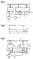
- Fig. 1
- ein Teil eines Blockschemas eines Tarifgerätes,
- Fig. 2
- ein Diagramm eines Signalverlaufes und
- Fig. 3
- ein Teil eines zweiten Blockschemas eines Tarifgerätes.
- Fig. 1
- part of a block diagram of a tariff device,
- Fig. 2
- a diagram of a waveform and
- Fig. 3
- part of a second block diagram of a tariff device.
In der Fig. 1 ist ein Mikrocomputer 1 mit einem parallelen Datenport 2, einem seriellen Datenport 3 und einem Steuerausgang 4 für Signale "Speicher lesen" bzw. "Speicher beschreiben" dargestellt. Weitere für den Betrieb des Mikrocomputers 1 und des Tarifgerätes wichtige Einzelheiten sind der Einfachheit halber weggelassen. Der parallele Datenport 2 ist über einen Datenbus 5 mit einem Datenspeicher 6 verbunden. Der Datenspeicher 6 ist aus zwei Speicherblöcken 6a und 6b zusammengesetzt, die beide als Schreib/Lesespeicher ausgebildet sind. Im Speicherblock 6a sind Messwerte und Parameter, die zur Verrechnung der konsumierten Energie oder Leistung wichtig sind, abgespeichert. Im Speicherblock 6b sind Parameter von untergeordneter Bedeutung, wie z. B. die Uhrzeit, das Datum u.s.w abgespeichert. Ein Programmspeicher zur Speicherung des Betriebsprogrammes des Tarifgerätes ist im Mikrocomputer 1 integriert. Der serielle Datenport 3 ist über zwei Leitungen 7a und 7b mit einer bidirektionalen optischen Schnittstelle 8 verbunden. Diese Schnittstelle 8 dient zur Datenübertragung mit einem hier nicht gezeichneten Ablesegerät. Die Leitung 7a überträgt die Daten vom Mikrocomputer 1 zur optischen Schnittstelle 8 und die Leitung 7b überträgt die Daten in der umgekehrten Richtung. Die Leitung 7b ist zusätzlich mit einem Eingang eines Zeitgliedes 9 verbunden. Ein Ausgang des Zeitgliedes 9 ist an einen ersten Eingang einer logischen Schaltung 10 angeschlossen. Der Steuerausgang 4 des Mikrocomputers 1 ist über eine Steuerleitung 11 mit einem zweiten Eingang der logischen Schaltung 10 und mit einem Steuereingang 12b des Speicherblockes 6b verbunden. Der Ausgang der logischen Schaltung 10 ist mit einem Steuereingang 12a des Speicherblockes 6a verbunden.1 shows a microcomputer 1 with a
Der Mikrocomputer 1 erhält inkrementale Impulse von einem hier nicht gezeichneten Elektrizitätszähler. Diese Impulse werden mit Parametern, die im Speicherblock 6a abgelegt sind, verknüpft und im Speicherblock 6a als Energie- und Leistungswerte aufsummiert. Die Energie- und Leistungswerte können auf einer nicht gezeichneten Anzeigeeinheit angezeigt werden. Für Verrechnungszwecke werden diese Daten über die optische Schnittstelle 8 in das Ablesegerät übertragen und von diesem an eine Datenverarbeitungsanlage zur Rechnungsstellung weitergegeben.The microcomputer 1 receives incremental pulses from an electricity meter, not shown here. These pulses are linked with parameters stored in the memory block 6a and summed up in the memory block 6a as energy and power values. The energy and power values can be displayed on a display unit, not shown. For billing purposes, this data is transmitted to the reading device via the
Eine Datenübertragung über die optische Schnittstelle 8 wird mit einem Aufforderungstelegramm vom Ablesegerät zum Mikrocomputer 1 eröffnet. Das Aufforderungstelegramm veranlasst den Mikrocomputer 1 Daten, die im Datenspeicher 6 abgelegt sind, über den Datenbus 5 und den parallelen Datenport 2 zu holen, in einen seriellen Datenstrom umzuwandeln und über den seriellen Datenport 3 und die Leitung 7a an die optische Schnittstelle 8 zu leiten. Umgekehrt können Daten vom Ablesegerät an die optische Schnittstelle 8 und von da über die Leitung 7b an den seriellen Datenport 3 des Mikrocomputers 1 übertragen werden. Der Mikrocomputer 1 wandelt die seriellen Daten in parallele Daten um und gibt sie über den parallelen Datenport 2 an den Datenspeicher 6 weiter. Daten können aus dem Datenspeicher 6 ausgelesen beziehungsweise eingeschrieben werden, wenn am Datenspeicher 6 die entsprechende Adresse anliegt und der Steuereingang 12a bzw. 12b das Signal "Speicher lesen" oder "Speicher beschreiben", beispielsweise logisch "1" für "lesen" und logisch "0" für "beschreiben" führt.A data transmission via the
Die Leitung 7b ist im normalen Betriebszustand des Tarifgerätes, d. h. wenn keine Ablesung stattfindet, in einem stabilen Zustand von beispielsweise logisch "1". Bei Beginn des Aufforderungstelegrammes ändert die Leitung 7b ihren Zustand von "1" zu "0". Durch den Zustandswechsel der Leitung 7b wird das Zeitglied 9 angestossen und für die Dauer einer Datenübertragung aktiviert. Sein Ausgang kippt von einem Zustand von beispielsweise "1" in einen Zustand "0". Die logische Schaltung 10 verknüpft das Zeitglied 9 und die Steuerleitung 11 derart, dass während der Datenübertragung der Speicherblock 6a gegen das Beschreiben gesperrt ist. Der Speicherblock 6a kann also während einer Datenübertragung mit dem Ablesegerät nur gelesen werden, währenddem der Speicherblock 6b sowohl gelesen als auch beschrieben werden kann.
Während einer Ablesung vom Elektrizitätszähler her eintreffende Impulse müssen zwischengespeichert werden. Sie können erst nach Beendigung der Ablesung in den Speicherblock 6a eingeschrieben werden. Die Impulse können beispielsweise in einem im Mikrocomputer 1 integrierten Schreib/Lesespeicher zwischengespeichert werden.Pulses arriving from the electricity meter during a reading must be buffered. They can only be written into the memory block 6a after the reading has ended. The pulses can be buffered, for example, in a read / write memory integrated in the microcomputer 1.
Während einer Datenübertragung mit dem Ablesegerät ist also ein vorbestimmter Speicherbereich, nämlich der Speicherblock 6a, des Datenspeichers 6 gegen das Einschreiben von Daten gesperrt. Die im Speicherblock 6a abgelegten Daten sind somit zuverlässig vor Veränderung geschützt.During a data transmission with the reading device, a predetermined memory area, namely the memory block 6a, of the
Die aus dem Zeitglied 9, der logischen Schaltung 10 und der Steuerleitung 11 bestehenden Sperrschaltung, die während der Datenübertragung den Speicherblock 6a gegen das Einschreiben von Daten sperrt, ist vorteilhaft derart ausgebildet, d. h. übersichtlich und zugänglich angeordnet, dass ihre Funktion bei der Eichung des Tarifgerätes auf einfache Art und Weise überprüfbar ist. Dies im Unterschied zu einer Software, bei der eine Funktionsprüfung sehr aufwendig ist.The blocking circuit consisting of the
Im oberen Diagrammteil der Fig. 2 ist das Eingangssignal und im unteren das Ausgangssignal des Zeitgliedes 9 dargestellt. Das Eingangssignal ändert dann und nur dann seinen Zustand, wenn eine Ablesung stattfindet. Mit dem ersten Flankenwechsel wird das Zeitglied 9 angestossen und damit ändert das Ausgangssignal für die Zeit T₁ den Zustand. Die Zeit T₁ setzt sich zusammen aus der Datenübertragungszeit T₂ und einer Sicherheitszeit T₃. Nach der Zeit T₁ nimmt der Ausgang des Zeitgliedes 6 wieder den ursprünglichen Zustand an.The upper part of the diagram in FIG. 2 shows the input signal and the lower part shows the output signal of the
Falls die Datenübertragungszeit T₂ nicht konstant ist, kann das Zeitglied 6 so ausgebildet sein, dass mit jedem Flankenwechsel des Eingangssignales die Sicherheitszeit T₃ neu gestartet wird.If the data transmission time T₂ is not constant, the
Die Fig. 3 zeigt eine Variante der Schaltung nach der Fig. 1, wobei gleiche Bezugszahlen wie in der Fig. 1 auf gleiche oder gleichwirkende Teile hinweisen. Der Datenspeicher 6 ist als einziger Speicherblock ausgebildet und in zwei Speicherbereiche 6c und 6d unterteilt. Im Speicherbereich 6d sind diejenigen Messwerte und Parameter abgespeichert, die für die Verrechnung wichtig sind. Im Speicherbereich 6c sind Parameter von untergeordneter Bedeutung abgespeichert. Der Ausgang des Zeitgliedes 9 ist mit einem ersten Eingang der logischen Schaltung 10 verbunden. Der Steuerausgang 4 des Mikro-Computers 1 ist über die Steuerleitung 11 an einen Steuereingang 13 des Datenspeichers 6 und an einen zweiten Eingang der logischen Schaltung 10 angeschlossen. Ein Adressport 14 des Mikrocomputers 1 ist über einen Adressbus 15 mit einem Adressport 16 des Datenspeichers 6 verbunden, wobei diejenige Adressleitung 17, die den Speicherbereich 6d definiert, mit einem dritten Eingang der logischen Schaltung 10 verbunden ist. Der Ausgang der logischen Schaltung 10 ist mit demjenigen Adresseingang 18 verbunden, die den Speicherbereich 6d definiert.FIG. 3 shows a variant of the circuit according to FIG. 1, the same reference numerals as in FIG. 1 indicating the same or equivalent parts. The
Die Funktion des Tarifgerätes nach der Fig. 3 unterscheidet sich von der Funktion des Tarifgerätes nach der Fig. 1 insofern, als nicht ein ganzer Speicherblock 6a, sondern nur ein Speicherbereich 6d während einer Datenübertragung gegen Beschreiben gesperrt ist, aber ein Lesen zulässt. Die logische Schaltung 10 decodiert zu diesem Zweck das Signal der Steuerleitung 11, den Ausgang des Zeitgliedes 9 und der Adressleitung 17. Der Speicherbereich 6d kann dadurch vergrössert werden, dass weitere logische Schaltungen 10 angeordnet sind, die weitere Adressleitungen mit der Steuerleitung 11 und dem Ausgang des Zeitgliedes 9 verknüpfen.The function of the tariff device according to FIG. 3 differs from the function of the tariff device according to FIG. 1 in that not an entire memory block 6a but only a
Die Schaltung nach der Fig. 3 ermöglicht eine kostengünstige Lösung in denjenigen Fällen, wo die Menge der gespeicherten Daten in einem Datenspeicher 6, der aus einem einzigen Baustein besteht, Platz hat.The circuit according to FIG. 3 enables a cost-effective solution in those cases where the amount of data stored has space in a
Bei dem beschriebenen Tarifgerät ist auf einfache Art und Weise überprüfbar, welche Daten mit einem Ablesegerät verändert werden können und welche nicht. Zu diesem Zwecke ist nur die Hardware zu überprüfen, was mit relativ geringem Aufwand möglich ist. Solche Tarifgeräte sind somit eichfähig.With the tariff device described, it is easy to check which data can be changed with a reading device and which cannot. For this purpose, only the hardware needs to be checked, which is possible with relatively little effort. Such tariff devices are therefore legal for trade.
Claims (4)
- A tariff arrangement comprising a microcomputer (1), a data memory (6), an interface (8) and an inhibiting circuit (9, 10, 11) which inhibits a predetermined memory region (6a; 6d) of the data memory (6) to prevent the writing in of data and in which the inhibition can be removed again for the input of data into the data memory (6), characterised in that the interface (8) serves for bidirectional transfer of data from and to an external terminal and that the inhibiting circuit (9, 10, 11) has a timing member (9) which can be so activated by a request telegram that causes data to be read out of the data memory (6) by way of the interface (8) that during a data transfer time (72) which is required for the reading-out operation and a safety time (T3) the writing in of data into the predetermined memory region (6a; 6d) is inhibited.
- A tariff arrangement according to claim 1 characterised in that the timing member (9) and a control line (11) which enables the data memory (6) for data to be written into same are linked to a logic circuit (10) in such a way that during the operation of reading out data the predetermined memory region (6a) is inhibited to prevent data from being written into same.
- A tariff arrangement according to claim 2 characterised in that a number of address lines (17) which corresponds to the predetermined memory region (6d) is linked to the logic circuit (10) and an address bus (15) between the microcomputer (1) and the data memory (6).
- A tariff arrangement according to one of the preceding claims characterised in that a randan access memory which is contained in the microcomputer (1) provides for intermediate storage of the data received from an electricity meter during the reading-out operation.
Priority Applications (1)
| Application Number | Priority Date | Filing Date | Title |
|---|---|---|---|
| AT90116348T ATE98023T1 (en) | 1989-12-15 | 1990-08-27 | TARIFF DEVICE WITH SECURE BI-DIRECTIONAL INTERFACE. |
Applications Claiming Priority (2)
| Application Number | Priority Date | Filing Date | Title |
|---|---|---|---|
| CH4514/89 | 1989-12-15 | ||
| CH451489 | 1989-12-15 |
Publications (2)
| Publication Number | Publication Date |
|---|---|
| EP0432367A1 EP0432367A1 (en) | 1991-06-19 |
| EP0432367B1 true EP0432367B1 (en) | 1993-12-01 |
Family
ID=4277515
Family Applications (1)
| Application Number | Title | Priority Date | Filing Date |
|---|---|---|---|
| EP90116348A Expired - Lifetime EP0432367B1 (en) | 1989-12-15 | 1990-08-27 | Device for calculating the tariff with secure bidirectional interface |
Country Status (13)
| Country | Link |
|---|---|
| US (1) | US5136514A (en) |
| EP (1) | EP0432367B1 (en) |
| JP (1) | JPH0654329B2 (en) |
| AT (1) | ATE98023T1 (en) |
| AU (1) | AU631692B2 (en) |
| CA (1) | CA2025249A1 (en) |
| DE (1) | DE59003693D1 (en) |
| DK (1) | DK0432367T3 (en) |
| ES (1) | ES2047221T3 (en) |
| FI (1) | FI906177A (en) |
| IE (1) | IE903807A1 (en) |
| NO (1) | NO905413L (en) |
| PT (1) | PT95981A (en) |
Families Citing this family (13)
| Publication number | Priority date | Publication date | Assignee | Title |
|---|---|---|---|---|
| JP2835215B2 (en) * | 1991-07-25 | 1998-12-14 | 株式会社東芝 | Nonvolatile semiconductor memory device |
| US5384712A (en) * | 1991-08-15 | 1995-01-24 | Eaton Corporation | Energy monitoring system for a plurality of local stations with snapshot polling from a central station |
| DE69227957T2 (en) * | 1991-08-15 | 1999-08-05 | Eaton Corp | Performance monitoring system for a plurality of local substations with an all-round instant value query from a central station |
| US5315531A (en) * | 1991-08-15 | 1994-05-24 | Westinghouse Electric Corp. | Energy monitoring system for a plurality of local stations with snapshot polling from a central station |
| JPH06194386A (en) * | 1992-12-24 | 1994-07-15 | Canon Inc | System interconnection unit |
| US5414994A (en) * | 1994-02-15 | 1995-05-16 | Ford Motor Company | Method and apparatus to limit a midbed temperature of a catalytic converter |
| DE19747391C2 (en) | 1997-10-27 | 1999-12-30 | Siemens Ag | Method of controlling an electricity meter and electricity meter |
| US6226600B1 (en) * | 1998-08-03 | 2001-05-01 | Rodenberg, Iii Ernest A. | Programmable electricity consumption monitor |
| US6381009B1 (en) | 1999-06-29 | 2002-04-30 | Nanometrics Incorporated | Elemental concentration measuring methods and instruments |
| US6889271B1 (en) * | 1999-06-30 | 2005-05-03 | General Electric Company | Methods and apparatus for meter I/O board addressing and communication |
| US20040027253A1 (en) * | 2002-08-12 | 2004-02-12 | Marsh Douglas G. | Automatic reading of a meter having a dial or numeric visual display |
| US7043380B2 (en) * | 2003-09-16 | 2006-05-09 | Rodenberg Iii Ernest Adolph | Programmable electricity consumption monitoring system and method |
| CN100492027C (en) * | 2006-12-08 | 2009-05-27 | 北京中星微电子有限公司 | Real time collection storage apparatus used for electric energy computation chip |
Family Cites Families (8)
| Publication number | Priority date | Publication date | Assignee | Title |
|---|---|---|---|---|
| GB1586771A (en) * | 1976-10-22 | 1981-03-25 | Plessey Co Ltd | Taximeter |
| SE425123B (en) * | 1979-08-21 | 1982-08-30 | Bjorn Gosta Erik Karlsson | PLANT FOR CENTRAL AND AUTOMATIC READING AND REGISTRATION OF SUBSCRIBERS 'ENERGY CONSUMPTION |
| DE3119812A1 (en) * | 1981-05-19 | 1982-12-16 | Kienzle Apparate Gmbh, 7730 Villingen-Schwenningen | ELECTRONIC TAXAMETER |
| EP0085117A1 (en) * | 1982-01-28 | 1983-08-10 | Mannesmann Kienzle GmbH | Volatile RAM data protection circuit |
| DE3203263A1 (en) * | 1982-02-01 | 1983-08-11 | Scheidt & Bachmann GmbH, 4050 Mönchengladbach | Method for transmitting and storing system-related data |
| US4998203A (en) * | 1985-03-12 | 1991-03-05 | Digiulio Peter C | Postage meter with a non-volatile memory security circuit |
| GB2183852A (en) * | 1985-11-27 | 1987-06-10 | Triad Communications Inc | Utility meter |
| US4809185A (en) * | 1986-09-02 | 1989-02-28 | Pitney Bowes Inc. | Secure metering device storage vault for a value printing system |
-
1990
- 1990-08-27 EP EP90116348A patent/EP0432367B1/en not_active Expired - Lifetime
- 1990-08-27 DK DK90116348.5T patent/DK0432367T3/en active
- 1990-08-27 DE DE90116348T patent/DE59003693D1/en not_active Expired - Fee Related
- 1990-08-27 ES ES90116348T patent/ES2047221T3/en not_active Expired - Lifetime
- 1990-08-27 AT AT90116348T patent/ATE98023T1/en not_active IP Right Cessation
- 1990-09-13 CA CA002025249A patent/CA2025249A1/en not_active Abandoned
- 1990-10-10 US US07/595,293 patent/US5136514A/en not_active Expired - Fee Related
- 1990-10-23 IE IE380790A patent/IE903807A1/en unknown
- 1990-10-31 AU AU65670/90A patent/AU631692B2/en not_active Ceased
- 1990-11-23 PT PT95981A patent/PT95981A/en not_active Application Discontinuation
- 1990-11-28 JP JP2323444A patent/JPH0654329B2/en not_active Expired - Lifetime
- 1990-12-14 FI FI906177A patent/FI906177A/en not_active IP Right Cessation
- 1990-12-14 NO NO90905413A patent/NO905413L/en unknown
Also Published As
| Publication number | Publication date |
|---|---|
| ES2047221T3 (en) | 1994-02-16 |
| DK0432367T3 (en) | 1994-04-18 |
| US5136514A (en) | 1992-08-04 |
| FI906177A (en) | 1991-06-16 |
| JPH03199977A (en) | 1991-08-30 |
| AU631692B2 (en) | 1992-12-03 |
| FI906177A0 (en) | 1990-12-14 |
| NO905413D0 (en) | 1990-12-14 |
| NO905413L (en) | 1991-06-17 |
| ATE98023T1 (en) | 1993-12-15 |
| CA2025249A1 (en) | 1991-06-16 |
| PT95981A (en) | 1992-08-31 |
| EP0432367A1 (en) | 1991-06-19 |
| DE59003693D1 (en) | 1994-01-13 |
| JPH0654329B2 (en) | 1994-07-20 |
| IE903807A1 (en) | 1991-06-19 |
| AU6567090A (en) | 1991-06-20 |
Similar Documents
| Publication | Publication Date | Title |
|---|---|---|
| EP0432367B1 (en) | Device for calculating the tariff with secure bidirectional interface | |
| DE2837201C2 (en) | ||
| DE4000443C2 (en) | ||
| DE3801699C2 (en) | ||
| DE19645745B4 (en) | Dynamic read / write memory | |
| DE4442636C2 (en) | System and method for testing an electronic circuit | |
| DE2621271A1 (en) | PORTABLE ELECTRONIC OBJECT | |
| DE2916840A1 (en) | ELECTRONICALLY CONTROLLED FRANKING MACHINE | |
| DE19748353C2 (en) | Information system usage system | |
| FI78574C (en) | Switching device for securing data in volatile write-read memory (RAM) | |
| EP1209631B1 (en) | Power supply arrangement for a security part of an apparatus | |
| DE2455440C3 (en) | Verification arrangement for a particular pulse pattern | |
| WO1998041880A2 (en) | Integrated circuit and method for testing the same | |
| DE69434037T2 (en) | Postage meter with additional indications | |
| DE3638735A1 (en) | Telecommunications network, in particular mobile radio network | |
| EP0649025A1 (en) | Static electricity meter | |
| DE3335549A1 (en) | Monitoring device for data processing system | |
| DE3931539A1 (en) | Terminal connector to voltage supply bus - has diode between bus and connector in front of output coupling capacitors | |
| DE3137152A1 (en) | Memory correction unit | |
| DE10145745A1 (en) | Integrated circuit and method for its operation | |
| DE4445801C2 (en) | Circuit arrangement for the control of dynamic memories by a microprocessor | |
| EP0356873B1 (en) | Serial data interface | |
| DE3400311C1 (en) | Data processing device with a processor | |
| DE3203263C2 (en) | ||
| DE10228527B3 (en) | Method for checking the refresh function of an information store |
Legal Events
| Date | Code | Title | Description |
|---|---|---|---|
| PUAI | Public reference made under article 153(3) epc to a published international application that has entered the european phase |
Free format text: ORIGINAL CODE: 0009012 |
|
| AK | Designated contracting states |
Kind code of ref document: A1 Designated state(s): AT BE CH DE DK ES FR GB GR IT LI NL SE |
|
| 17P | Request for examination filed |
Effective date: 19910710 |
|
| 17Q | First examination report despatched |
Effective date: 19921218 |
|
| RAP1 | Party data changed (applicant data changed or rights of an application transferred) |
Owner name: LANDIS & GYR BUSINESS SUPPORT AG |
|
| GRAA | (expected) grant |
Free format text: ORIGINAL CODE: 0009210 |
|
| AK | Designated contracting states |
Kind code of ref document: B1 Designated state(s): AT BE CH DE DK ES FR GB GR IT LI NL SE |
|
| REF | Corresponds to: |
Ref document number: 98023 Country of ref document: AT Date of ref document: 19931215 Kind code of ref document: T |
|
| GBT | Gb: translation of ep patent filed (gb section 77(6)(a)/1977) |
Effective date: 19931215 |
|
| REF | Corresponds to: |
Ref document number: 59003693 Country of ref document: DE Date of ref document: 19940113 |
|
| REG | Reference to a national code |
Ref country code: ES Ref legal event code: FG2A Ref document number: 2047221 Country of ref document: ES Kind code of ref document: T3 |
|
| ET | Fr: translation filed | ||
| ITF | It: translation for a ep patent filed |
Owner name: STUDIO JAUMANN |
|
| REG | Reference to a national code |
Ref country code: DK Ref legal event code: T3 |
|
| REG | Reference to a national code |
Ref country code: GR Ref legal event code: FG4A Free format text: 3010665 |
|
| PGFP | Annual fee paid to national office [announced via postgrant information from national office to epo] |
Ref country code: GB Payment date: 19940720 Year of fee payment: 5 |
|
| PGFP | Annual fee paid to national office [announced via postgrant information from national office to epo] |
Ref country code: GR Payment date: 19940727 Year of fee payment: 5 |
|
| PGFP | Annual fee paid to national office [announced via postgrant information from national office to epo] |
Ref country code: FR Payment date: 19940802 Year of fee payment: 5 |
|
| PGFP | Annual fee paid to national office [announced via postgrant information from national office to epo] |
Ref country code: SE Payment date: 19940809 Year of fee payment: 5 Ref country code: DK Payment date: 19940809 Year of fee payment: 5 Ref country code: AT Payment date: 19940809 Year of fee payment: 5 |
|
| PGFP | Annual fee paid to national office [announced via postgrant information from national office to epo] |
Ref country code: ES Payment date: 19940816 Year of fee payment: 5 Ref country code: BE Payment date: 19940816 Year of fee payment: 5 |
|
| PG25 | Lapsed in a contracting state [announced via postgrant information from national office to epo] |
Ref country code: LI Effective date: 19940831 Ref country code: CH Effective date: 19940831 |
|
| PGFP | Annual fee paid to national office [announced via postgrant information from national office to epo] |
Ref country code: NL Payment date: 19940831 Year of fee payment: 5 |
|
| PGFP | Annual fee paid to national office [announced via postgrant information from national office to epo] |
Ref country code: DE Payment date: 19940919 Year of fee payment: 5 |
|
| PLBE | No opposition filed within time limit |
Free format text: ORIGINAL CODE: 0009261 |
|
| STAA | Information on the status of an ep patent application or granted ep patent |
Free format text: STATUS: NO OPPOSITION FILED WITHIN TIME LIMIT |
|
| 26N | No opposition filed | ||
| EAL | Se: european patent in force in sweden |
Ref document number: 90116348.5 |
|
| REG | Reference to a national code |
Ref country code: CH Ref legal event code: PL |
|
| PG25 | Lapsed in a contracting state [announced via postgrant information from national office to epo] |
Ref country code: GB Effective date: 19950827 Ref country code: DK Effective date: 19950827 Ref country code: AT Effective date: 19950827 |
|
| REG | Reference to a national code |
Ref country code: DK Ref legal event code: EBP |
|
| PG25 | Lapsed in a contracting state [announced via postgrant information from national office to epo] |
Ref country code: SE Effective date: 19950828 Ref country code: ES Free format text: LAPSE BECAUSE OF EXPIRATION OF PROTECTION Effective date: 19950828 |
|
| PG25 | Lapsed in a contracting state [announced via postgrant information from national office to epo] |
Ref country code: BE Effective date: 19950831 |
|
| PG25 | Lapsed in a contracting state [announced via postgrant information from national office to epo] |
Ref country code: GR Free format text: THE PATENT HAS BEEN ANNULLED BY A DECISION OF A NATIONAL AUTHORITY Effective date: 19960228 |
|
| BERE | Be: lapsed |
Owner name: LANDIS & GYR BUSINESS SUPPORT A.G. Effective date: 19950831 |
|
| PG25 | Lapsed in a contracting state [announced via postgrant information from national office to epo] |
Ref country code: NL Effective date: 19960301 |
|
| GBPC | Gb: european patent ceased through non-payment of renewal fee |
Effective date: 19950827 |
|
| PG25 | Lapsed in a contracting state [announced via postgrant information from national office to epo] |
Ref country code: FR Effective date: 19960430 |
|
| REG | Reference to a national code |
Ref country code: GR Ref legal event code: MM2A Free format text: 3010665 |
|
| NLV4 | Nl: lapsed or anulled due to non-payment of the annual fee |
Effective date: 19960301 |
|
| PG25 | Lapsed in a contracting state [announced via postgrant information from national office to epo] |
Ref country code: DE Effective date: 19960501 |
|
| EUG | Se: european patent has lapsed |
Ref document number: 90116348.5 |
|
| REG | Reference to a national code |
Ref country code: FR Ref legal event code: ST |
|
| REG | Reference to a national code |
Ref country code: ES Ref legal event code: FD2A Effective date: 19990601 |
|
| PG25 | Lapsed in a contracting state [announced via postgrant information from national office to epo] |
Ref country code: IT Free format text: LAPSE BECAUSE OF NON-PAYMENT OF DUE FEES;WARNING: LAPSES OF ITALIAN PATENTS WITH EFFECTIVE DATE BEFORE 2007 MAY HAVE OCCURRED AT ANY TIME BEFORE 2007. THE CORRECT EFFECTIVE DATE MAY BE DIFFERENT FROM THE ONE RECORDED. Effective date: 20050827 |