EP0430951B1 - Magnetic massage-therapy device - Google Patents
Magnetic massage-therapy device Download PDFInfo
- Publication number
- EP0430951B1 EP0430951B1 EP89907138A EP89907138A EP0430951B1 EP 0430951 B1 EP0430951 B1 EP 0430951B1 EP 89907138 A EP89907138 A EP 89907138A EP 89907138 A EP89907138 A EP 89907138A EP 0430951 B1 EP0430951 B1 EP 0430951B1
- Authority
- EP
- European Patent Office
- Prior art keywords
- frequency
- treatment appliance
- appliance according
- magnetic
- field coil
- Prior art date
- Legal status (The legal status is an assumption and is not a legal conclusion. Google has not performed a legal analysis and makes no representation as to the accuracy of the status listed.)
- Expired - Lifetime
Links
- 238000002078 massotherapy Methods 0.000 title 1
- 241001465754 Metazoa Species 0.000 claims abstract description 4
- 239000004020 conductor Substances 0.000 claims description 10
- 239000004753 textile Substances 0.000 claims description 6
- 239000000463 material Substances 0.000 claims description 3
- 239000004033 plastic Substances 0.000 claims description 3
- 239000013013 elastic material Substances 0.000 claims description 2
- 239000005445 natural material Substances 0.000 claims description 2
- 230000000712 assembly Effects 0.000 claims 1
- 238000000429 assembly Methods 0.000 claims 1
- 230000000694 effects Effects 0.000 abstract description 7
- 230000005672 electromagnetic field Effects 0.000 abstract description 5
- 230000017531 blood circulation Effects 0.000 abstract description 3
- 230000010355 oscillation Effects 0.000 abstract description 2
- 230000032630 lymph circulation Effects 0.000 abstract 1
- 239000007787 solid Substances 0.000 abstract 1
- 238000002560 therapeutic procedure Methods 0.000 description 5
- 230000000295 complement effect Effects 0.000 description 3
- 238000010586 diagram Methods 0.000 description 3
- 208000027418 Wounds and injury Diseases 0.000 description 2
- 230000009286 beneficial effect Effects 0.000 description 2
- 239000008280 blood Substances 0.000 description 2
- 210000004369 blood Anatomy 0.000 description 2
- 230000006378 damage Effects 0.000 description 2
- 210000003414 extremity Anatomy 0.000 description 2
- 239000004744 fabric Substances 0.000 description 2
- 239000006260 foam Substances 0.000 description 2
- 208000014674 injury Diseases 0.000 description 2
- 230000001926 lymphatic effect Effects 0.000 description 2
- 230000002572 peristaltic effect Effects 0.000 description 2
- 230000001225 therapeutic effect Effects 0.000 description 2
- 241000282412 Homo Species 0.000 description 1
- 230000006978 adaptation Effects 0.000 description 1
- 239000000654 additive Substances 0.000 description 1
- 230000000996 additive effect Effects 0.000 description 1
- 210000004204 blood vessel Anatomy 0.000 description 1
- 239000012141 concentrate Substances 0.000 description 1
- 239000003814 drug Substances 0.000 description 1
- 230000005288 electromagnetic effect Effects 0.000 description 1
- 230000002349 favourable effect Effects 0.000 description 1
- 230000003993 interaction Effects 0.000 description 1
- 210000002751 lymph Anatomy 0.000 description 1
- 210000004324 lymphatic system Anatomy 0.000 description 1
- 230000005415 magnetization Effects 0.000 description 1
- 238000000034 method Methods 0.000 description 1
- 230000004089 microcirculation Effects 0.000 description 1
- 210000003205 muscle Anatomy 0.000 description 1
- 230000008092 positive effect Effects 0.000 description 1
- 238000002360 preparation method Methods 0.000 description 1
- 230000001681 protective effect Effects 0.000 description 1
- 230000002040 relaxant effect Effects 0.000 description 1
- 210000002027 skeletal muscle Anatomy 0.000 description 1
- 230000002195 synergetic effect Effects 0.000 description 1
- 210000001519 tissue Anatomy 0.000 description 1
- 210000000689 upper leg Anatomy 0.000 description 1
- 238000004804 winding Methods 0.000 description 1
Images


Classifications
-
- A—HUMAN NECESSITIES
- A61—MEDICAL OR VETERINARY SCIENCE; HYGIENE
- A61H—PHYSICAL THERAPY APPARATUS, e.g. DEVICES FOR LOCATING OR STIMULATING REFLEX POINTS IN THE BODY; ARTIFICIAL RESPIRATION; MASSAGE; BATHING DEVICES FOR SPECIAL THERAPEUTIC OR HYGIENIC PURPOSES OR SPECIFIC PARTS OF THE BODY
- A61H23/00—Percussion or vibration massage, e.g. using supersonic vibration; Suction-vibration massage; Massage with moving diaphragms
- A61H23/02—Percussion or vibration massage, e.g. using supersonic vibration; Suction-vibration massage; Massage with moving diaphragms with electric or magnetic drive
- A61H23/0218—Percussion or vibration massage, e.g. using supersonic vibration; Suction-vibration massage; Massage with moving diaphragms with electric or magnetic drive with alternating magnetic fields producing a translating or oscillating movement
-
- A—HUMAN NECESSITIES
- A61—MEDICAL OR VETERINARY SCIENCE; HYGIENE
- A61H—PHYSICAL THERAPY APPARATUS, e.g. DEVICES FOR LOCATING OR STIMULATING REFLEX POINTS IN THE BODY; ARTIFICIAL RESPIRATION; MASSAGE; BATHING DEVICES FOR SPECIAL THERAPEUTIC OR HYGIENIC PURPOSES OR SPECIFIC PARTS OF THE BODY
- A61H23/00—Percussion or vibration massage, e.g. using supersonic vibration; Suction-vibration massage; Massage with moving diaphragms
- A61H23/02—Percussion or vibration massage, e.g. using supersonic vibration; Suction-vibration massage; Massage with moving diaphragms with electric or magnetic drive
- A61H2023/0209—Percussion or vibration massage, e.g. using supersonic vibration; Suction-vibration massage; Massage with moving diaphragms with electric or magnetic drive powered with frequencies not related to mains frequency
-
- A—HUMAN NECESSITIES
- A61—MEDICAL OR VETERINARY SCIENCE; HYGIENE
- A61H—PHYSICAL THERAPY APPARATUS, e.g. DEVICES FOR LOCATING OR STIMULATING REFLEX POINTS IN THE BODY; ARTIFICIAL RESPIRATION; MASSAGE; BATHING DEVICES FOR SPECIAL THERAPEUTIC OR HYGIENIC PURPOSES OR SPECIFIC PARTS OF THE BODY
- A61H2201/00—Characteristics of apparatus not provided for in the preceding codes
- A61H2201/10—Characteristics of apparatus not provided for in the preceding codes with further special therapeutic means, e.g. electrotherapy, magneto therapy or radiation therapy, chromo therapy, infrared or ultraviolet therapy
-
- A—HUMAN NECESSITIES
- A61—MEDICAL OR VETERINARY SCIENCE; HYGIENE
- A61H—PHYSICAL THERAPY APPARATUS, e.g. DEVICES FOR LOCATING OR STIMULATING REFLEX POINTS IN THE BODY; ARTIFICIAL RESPIRATION; MASSAGE; BATHING DEVICES FOR SPECIAL THERAPEUTIC OR HYGIENIC PURPOSES OR SPECIFIC PARTS OF THE BODY
- A61H2201/00—Characteristics of apparatus not provided for in the preceding codes
- A61H2201/50—Control means thereof
- A61H2201/5007—Control means thereof computer controlled
-
- A—HUMAN NECESSITIES
- A61—MEDICAL OR VETERINARY SCIENCE; HYGIENE
- A61H—PHYSICAL THERAPY APPARATUS, e.g. DEVICES FOR LOCATING OR STIMULATING REFLEX POINTS IN THE BODY; ARTIFICIAL RESPIRATION; MASSAGE; BATHING DEVICES FOR SPECIAL THERAPEUTIC OR HYGIENIC PURPOSES OR SPECIFIC PARTS OF THE BODY
- A61H2205/00—Devices for specific parts of the body
- A61H2205/08—Trunk
-
- A—HUMAN NECESSITIES
- A61—MEDICAL OR VETERINARY SCIENCE; HYGIENE
- A61N—ELECTROTHERAPY; MAGNETOTHERAPY; RADIATION THERAPY; ULTRASOUND THERAPY
- A61N2/00—Magnetotherapy
Landscapes
- Health & Medical Sciences (AREA)
- Veterinary Medicine (AREA)
- Public Health (AREA)
- General Health & Medical Sciences (AREA)
- Animal Behavior & Ethology (AREA)
- Life Sciences & Earth Sciences (AREA)
- Rehabilitation Therapy (AREA)
- Physical Education & Sports Medicine (AREA)
- Pain & Pain Management (AREA)
- Epidemiology (AREA)
- Engineering & Computer Science (AREA)
- Biomedical Technology (AREA)
- Nuclear Medicine, Radiotherapy & Molecular Imaging (AREA)
- Radiology & Medical Imaging (AREA)
- Magnetic Treatment Devices (AREA)
Abstract
Description
Die Erfindung betrifft eine Behandlungsvorrichtung für einen menschlichen oder tierischen Körper oder Körperteil mit einer Feldspulenanordnung, die mit einem netzgespeisten, niederfrequenten Impulsstromgenerator verbunden ist und in der ein Magnetplättchen elastisch gehalten angeordnet ist, so daß es in dem niederfrequenten Magnetfeld der Feldspulenanordnung oszilliert.The invention relates to a treatment device for a human or animal body or body part with a field coil arrangement, which is connected to a mains-powered, low-frequency pulse current generator and in which a magnetic plate is arranged elastically so that it oscillates in the low-frequency magnetic field of the field coil arrangement.
Eine derartige Behandlungsvorrichtung ist aus der DE-A-3 335 018 vorbekannt. Diese Vorrichtung weist jedoch jeweils zwei den Patientenkörper beaufschlagende Feldspulen auf, die an jeweils einem Impulsstromgenerator angeschlossen sind. Diese Impulsgeneratoren arbeiten mit sehr verschiedenen Frequenzen, nämlich einer niedrigen Grundfrequenz und einer hohen Modulationsfrequenz von über 10 kHz. Dies ist ein hoher Aufwand und erfordert jeweils eine geeignete Abstimmung der Einstellung der beiden Generatoren auf jeweils vorliegende Behandlungserfordernisse. Das Permanentmagnetplättchen ist in dem Feldbereich der beiden Feldspulen beweglich gehalten und übt durch seine Oszillation nur eine elektromagnetische Wirkung auf den beabstandeten Körper aus.Such a treatment device is previously known from DE-A-3 335 018. However, this device in each case has two field coils which act on the patient's body and which are each connected to a pulse current generator. These pulse generators work with very different frequencies, namely a low fundamental frequency and a high modulation frequency of over 10 kHz. This is a high cost and requires a suitable adjustment of the setting of the two generators to the respective treatment requirements. The permanent magnet plate is held movably in the field area of the two field coils and, due to its oscillation, only exerts an electromagnetic effect on the spaced-apart body.
Weiterhin ist aus der FR-A-2 585 579 eine Behandlungsvorrichtung bekannt, deren Spulen nur einseitig mit dem Frequenzgenerator verbunden sind und miteinander isoliert und zum Körper hin nicht isoliert sind, sondern durch einen Schutzschleier nur vor direkter Berührung geschützt sind. Vielmehr besteht hierbei über die spulenartige Leiteranordnung durch die nicht völlig isolierende Umhüllung eine elektrisch leitende Verbindung zum Körper des Patienten, den bei Anlegen zweier solcher Elektroden ein Mikrostrom durchfließt, der aus einer Mikrobatterie geliefert wird, wobei jede der Elektroden an einen Pol des Frequenzgenerators angechlossen ist. Die Permanentmagnete sind in dem Innenbereich der spulenartigen Leiteranordnungen gehalten und nicht unmittelbar mit dem Körper in Kontakt. Der Mikrostrom - ein höherer wird von einem Körper nicht ertragen - durchfließt das Leitergebilde nur beschränkt da er über den Leiter verteilt diesen seitlich verläßt. Ein magnetiches Wechselfeld, das in der Lage wäre, eine Schwingungsbewegung der Permanentmagnete zu bewirken, vermag ein solcher Mikrostrom nicht zu erzeugen. Auch würde sich eine mechanische Magnetschwingung nur beschränkt durch die umgebende Leiteranordnung hindurch auf den Körper übertragen. Weiterhin ist der Körper außenseitig zum spulenartigen Leiter angeordnet, so daß nur ein geringer Bruchteil des sehr schwachen durch den Mikrostrom erzeugten magnetischen Feldes den Körper trifft.Furthermore, from FR-A-2 585 579 a treatment device is known, the coils of which are only connected on one side to the frequency generator and are insulated from one another and are not insulated from the body, but are only protected from direct contact by a protective veil. Rather, there is an electrically conductive connection to the patient's body through the coil-like conductor arrangement due to the not completely insulating sheath, through which a microcurrent flows when two such electrodes are applied, which current consists of a Micro battery is supplied, wherein each of the electrodes is connected to a pole of the frequency generator. The permanent magnets are held in the inner region of the coil-like conductor arrangements and are not in direct contact with the body. The microcurrent - a higher one cannot be borne by a body - flows through the conductor structure only to a limited extent, since it distributes it laterally over the conductor. Such a microcurrent cannot generate an alternating magnetic field that would be capable of causing the permanent magnets to vibrate. A mechanical magnetic vibration would also be transmitted to the body only to a limited extent through the surrounding conductor arrangement. Furthermore, the body is arranged on the outside of the coil-like conductor, so that only a small fraction of the very weak magnetic field generated by the microcurrent hits the body.
Weiterhin ist aus der EP-A-0 005 713 eine Magnetspulenanordnung bekannt, die von Niederfrequenzstrom gespeist ist und in der ein menschlicher Körper anzuordnen ist, wobei an dem Körper ein hochpermeables Plättchen angeordnet wird, das das niederfrequente Magnetfeld konzentriert.Furthermore, EP-A-0 005 713 discloses a magnet coil arrangement which is fed by low-frequency current and in which a human body is to be arranged, a high-permeability plate which concentrates the low-frequency magnetic field being arranged on the body.
Die Aufgabe der Erfindung ist es, die eingangs genannte Vorrichtung zu verbessern und eine Erhöhung der Wirksamkeit der Niederfrequenztherapie und eine Erweiterung von deren Anwendungsgebiet zu erbringen.The object of the invention is to improve the device mentioned at the outset and to provide an increase in the effectiveness of low-frequency therapy and an extension of its field of application.
Die Lösung der Aufgabe besteht darin, daß mehrere Magnetplättchen gegeneinander verschwenkbar in einer Magnetdecke oder einer körpergerecht gestalteten Magnetschürze gehalten sind und zwischen den Magnetplättchen elastisches Material eingelagert ist, durch das Nähte hindurchgenäht sind, und daß die Feldspulenanordnung aus nur einer hohlzylindrischen oder abgeflacht-hohlzylindrischen Feldspule oder aus mehreren Spulenabschnitten besteht, die nebeneinander angeordnet sind und an den einzigen Impulsstromgenerator gleichsinnig wirkend angeschlossen sind.The solution to the problem is that a plurality of magnetic plates are held pivotably relative to one another in a magnetic blanket or a magnetically designed magnetic apron and elastic material is embedded between the magnetic plates by the seams are sewn through, and that the field coil arrangement consists of only a hollow cylindrical or flattened hollow cylindrical field coil or of several coil sections which are arranged next to one another and are connected in the same direction to the single pulse current generator.
Nach der Erfindung ist der Körper oder Körperteil in der Spulenanordnung anzuordnen und die schwenkbaren Magnetplättchen sind mit der Decke oder Schürze unmittelbar an dem Körper oder Körperteil anzuordnen. Die Spule aus isolierten Leitern ist jeweils mit ihren beiden Enden an komplementäre Anschlüsse der niederfrequenten Stromquelle angeschlossen, die eingangsseitig netzgespeist ist, wobei der niederfrequente Stromfluß so bemessen ist, daß die Magnetplättchen in dem niederfrequenten Magnetfeld der Feldspulen bildenden Spulen den Körper massierende Vibrationen ausführen.According to the invention, the body or body part is to be arranged in the coil arrangement and the pivotable magnetic plates are to be arranged directly on the body or body part with the blanket or apron. The coil of insulated conductors is connected at its two ends to complementary connections of the low-frequency current source, which is mains-fed on the input side, the low-frequency current flow being dimensioned such that the magnetic plates in the low-frequency magnetic field of the coils forming the field coils cause the body to vibrate massively.
Vorteilhafte Ausgestaltungen sind in den Unteransprüchen angegeben.Advantageous refinements are specified in the subclaims.
Die erfinderische Vorrichtung ist sehr nützlich in der physikalischen Medizin und zur Rehabilitation von Personen. Diese Neuerung erbringt eine Verbesserung des bekannten Verfahrens der Anwendung eines niederfrequenten elektromagnetischen Feldes, Niederfrequenztherapie genannt. Die Magnetplättchen bestehen vorteilhaft aus Permanentmagnetmaterial und sind in einer Decke oder Bandage gegeneinander beabstandet und gegeneinander schwenkbar gehalten, so daß sie auf dem Behandlungsobjekt einfach angeordnet und gehalten werden können, jedoch in dem elektromagnetischen Feld durch die Interaktion der Magnetfelder Schwenkbewegungen ausführen, welche ergänzend zu der therapeutischen Wirkung der Magnetfelder einen therpeutischen Massageeffekt vorteilhaft erbringen.The inventive device is very useful in physical medicine and for the rehabilitation of people. This innovation brings about an improvement in the known method of using a low-frequency electromagnetic field, called low-frequency therapy. The magnetic plates are advantageously made of permanent magnet material and are spaced from each other in a blanket or bandage and held pivotably against each other, so that they can be easily arranged and held on the treatment object, but perform pivoting movements in the electromagnetic field through the interaction of the magnetic fields, which are complementary to that therapeutic effect of the magnetic fields advantageously provide a therapeutic massage effect.
In einer vorteilhaften Ausgestaltung der Gesamtvorrichtung ist die Spulenanordnung, die der Erzeugung des Niederfrequenzfeldes dient und das Behandlungsobjekt und die Permanentmagnetanordnung, d.h. die Magnetträgerdecke oder -bandage, umschließt, aus biegsamen Spulen besteht, wodurch der Transport und die Handhabung der Anordnung vereinfacht ist.In an advantageous embodiment of the overall device, the coil arrangement which serves to generate the low-frequency field and the treatment object and the permanent magnet arrangement, i.e. the magnetic carrier cover or bandage, encloses, consists of flexible coils, whereby the transport and handling of the arrangement is simplified.
Eine vorteilhafte Ausgestaltung der Vorrichtung ist von einem Niederfrequenz-Impulsgenerator mit vorgebbarer Frequenz und Amplitude gespeist.An advantageous embodiment of the device is fed by a low-frequency pulse generator with a predeterminable frequency and amplitude.
Medizinisch-wissenschaftliche Untersuchungen mit der neuartigen Vorrichtung erwiesen deren vorteilhafte Wirkungen gegenüber der vorbekannten. Die Versuche an Menschen und Tiere erwiesen eine wesentlich höhere Wirksamkeit bei der Behandlung von posttraumatischen Zuständen im Vergleich zur vorbekannten reinen Niederfrequneztherapie. Die Versuche wurden mti einem elektromagnetischen Niederfrequenz-Impulsgeber in zwei Ausführungen vorgenommen und zwar: erstens mit Erzeugung von Impulsen einer Frequenz, die in einem Bereich zwischen 0,5 bis 30 Hz vorgebbar war, und deren Impulse aus Wellen einer sinusförmigen oder halbsinusförmigen Gestalt mit einer Grundfrequenz von 60 Hz bestanden, und zweitens mit Rechteckimpulsen mit einer vorgebbaren Frequenz im Frequenzbereich zwischen 1 - 1000 Hz. Die Feldspulenanordnung war bei den Versuchen in bekannter Form ausgestaltet.Medical-scientific examinations with the novel device proved their advantageous effects compared to the previously known. The trials on humans and animals showed a significantly higher effectiveness in the treatment of post-traumatic conditions in comparison to the previously known pure low-frequency therapy. The tests were carried out with an electromagnetic low-frequency pulse generator in two versions: firstly, with the generation of pulses of a frequency that could be specified in a range between 0.5 to 30 Hz, and their pulses from waves of a sinusoidal or semi-sinusoidal shape with a Basic frequency of 60 Hz existed, and secondly with square-wave pulses with a predeterminable frequency in the frequency range between 1 and 1000 Hz.
Teil der neuarigen Vorrichtung ist eine besonders ausgestaltete Magnet-Decke. Sie besteht aus vielen kleinen Permanentmagneten, die in bestimmter Weise orientiert und in bestimmter Weise voneinander getrennt, zueinander angeordnet sind. Hiermit entsteht in einem elektromagnetischen Niederfrequenzfeld eine sehr feine Vibration der starren, beweglich gelagerten Magnete, die eine Mikromassage der damit bedeckten Gefäße bewirkt. Der Haupteffekt dieser Mikromassage ist eine Erweiterung der kleinen Blutgefäße und eine Verbesserung des Flusses im lymphatischen System, also eine verbesserte Lymphdrainage. Darüberhinaus erbringt diese Massageart einen Erholungseffekt auf die betroffene Skelettmuskulatur. Diese Effekte überlagern die bekannten positiven Effekte der Magnet- und der Niederfrequenztherapie und erbringen einen synergistischen Effekt. Der Massageeffekt ist bereits nach wenigen Minuten spürbar, und die dadurch auftretende Entspannung und erhöhte Durchblutung ermöglicht, daß die nur langzeitlich wirkend spürbare Niederfrequenztherapie ihre Wirkung besser entfaltet.Part of the novel device is a specially designed magnetic blanket. It consists of many small permanent magnets, which are oriented in a certain way and separated from each other in a certain way, arranged to each other. This creates in an electromagnetic Low frequency field a very fine vibration of the rigid, movably mounted magnets, which causes a micro massage of the vessels covered with them. The main effect of this micro massage is an enlargement of the small blood vessels and an improvement in the flow in the lymphatic system, i.e. an improved lymphatic drainage. In addition, this type of massage has a relaxing effect on the affected skeletal muscles. These effects overlay the known positive effects of magnet and low frequency therapy and produce a synergistic effect. The massage effect is noticeable after just a few minutes, and the relaxation and increased blood flow that results from this enable the low-frequency therapy, which can only be felt for a long time, to develop its effect better.
Vorteilhaft hat sich gezeigt, daß mit den Permanentmagneten ausgerüstete Bandagen, die zur Pressur von Gliedmaßen mit Verletzungen, z.B. Zerrungen oder Muskelrissen, dienen, wenn sie in dem Niederfrequenzfeld zur Massagevibration erregt wurden, den bei Bandagen üblichen nachteiligen Lymph- und Blutstau in dem herzfernen Extremitätenabschnitt hinter der Bandage vermeiden, so daß eine schnellere und schmerz- und nachbehandlungsfreie Heilung der Verletzung bewirkt wurde.It has been shown to be advantageous that bandages equipped with the permanent magnets, which are used for pressing limbs with injuries, e.g. Strains or muscle tears, if they are excited to massage vibration in the low-frequency field, serve to avoid the disadvantageous lymphatic and blood congestion in the distal extremity section behind the bandage, which is typical for bandages, so that the injury was healed more quickly and without pain and after-treatment.
Vorteilhafte Ausführungsformen und Applikationen sind in den Figuren 1 bis 9 dargestellt.
- Fig. 1
- zeigt eine Schaltung eines Impulsgenerators der Vorrichtung;
- Fig. 2
- zeigt einen Ausschnitt einer Magnetanordnung in einer Decke in Aufsicht;
- Fig. 2a
- zeigt einenk Querschnitt zu Fig. 2;
- Fig. 3
- zeigt eine schürzenarige Decke mit einer weiteren Magnetanordnung;
- Fig. 4
- zeigt eine Feldspulenanordnung teilweise geöffnet teilweise schematisch in Aufsicht;
- Fig. 4a
- zeigt einen Querschnitt zu Fig. 3;
- Fig. 5
- zeigt eine elektrische Schaltung der Feldspulenanordnung zu Fig. 4;
- Fig. 6
- zeigt eine weitere Feldspulenanordnung;
- Fig. 6a
- zeigt einen Querschnitt zu Fig. 6 im vergrößerten Ausschnitt;
- Fig. 6b
- zeigt einen Querschnitt zu Fig. 6;
- Fig. 7
- zeigt eine elektrische Schaltung der Feldspulenanordnung zu Fig. 6;
- Fig. 8
- zeigt ein Blockschaltbild einer Gesamtanordnung;
- Fig. 9
- zeigt verschiedene Anordnungen der Vorrichtung an
- a - d
- einem Patienten.
- Fig. 1
- shows a circuit of a pulse generator of the device;
- Fig. 2
- shows a section of a magnet arrangement in a ceiling in supervision;
- Fig. 2a
- shows a cross section to Fig. 2;
- Fig. 3
- shows an apron-like blanket with another magnet arrangement;
- Fig. 4
- shows a field coil arrangement partially opened partially schematically in supervision;
- Fig. 4a
- shows a cross section to Fig. 3;
- Fig. 5
- shows an electrical circuit of the field coil arrangement of Fig. 4;
- Fig. 6
- shows a further field coil arrangement;
- Fig. 6a
- shows a cross section to Figure 6 in an enlarged section.
- Fig. 6b
- shows a cross section to Fig. 6;
- Fig. 7
- shows an electrical circuit of the field coil arrangement of Fig. 6;
- Fig. 8
- shows a block diagram of an overall arrangement;
- Fig. 9
- shows various arrangements of the device
- a - d
- a patient.
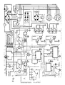
Fig. 1 zeigt ein Schaltbild des elektrischen Impulsgenerators. Dieser wird vom Wechselstromnetz (60 Hz, 110 V) gespeist, wenn der Schalter (SWA) eingeschaltet ist. Die Absicherung geschieht über die Sicherung (F1), und der Betrieb ist durch die Kontrolleuchte (B1) angezeigt. Der Betreibsartenschalter (SW3) dient der Umschaltung zwischen einer Betriebsart, bei der mit Hilfe der Netzfrequenz gearbeitet wird, wobei in seiner Aus-Stellung Signale einer Impulsfrequenz zwischen 0,5 - 30 Hz erzeugt werden und Signale mit sinusförmigem oder halbsinusförmigem Verlauf entstehen. Die Stromversorgung des ersten Oszillators (IC1) erfolgt über den Netztransformator (TR2), einen Netzgleichrichter, eine zweite Sicherung (F2) und einen Relaiskontakt eines ersten Relais (R1). Dann erzeugt der integrierte erste Oszillator (IC1), abhangig von den mit einem Frequenz-Bereichsschalter (P2) angeschalteten Kapazitäten, eine jeweils vorgegebene Frequenz zwischen 0,5 und 30 Hz. Das Oszillatorsignal verstärkt der Transistor (T1), dessen Signal einen Triac (TRI) ansteuert, der das Wechselspannungseingangssignal entsprechend getaktet einem Signaltransformator (TR1) zuführt. Dessen Sekundärwicklungen werden mit dem Leistungswahlschalter (P1) ausgewählt, und das ausgewählte Signal wird über einen Schalter (SW2), je nach dessen Stellung direkt oder über einen Halbwellengleichrichter (D), dem Ausgang zugeführt. Es werden demgemäß entweder Voll- oder Halbwellen-Ausgangssignale periodisch gemäß der Oszillatorfrequenz erzeugt. Gleichgerichtet und gefiltert ist das Ausgangssignal, das an den Steckerbuchsen (CO) abgegeben wird, einem Pegelmesser (MA) zugeführt Dessen Skala ist vorteilhaft entsprechend der Magentfeldstarke der Feldspule kalibriert. Eine Kontrolleuchte (LB2) zeigt den Betriebszustand. Wenn der Bereichsschalter (P2) in einer besonderen Endstellung (6) ist, ist das erste Relais (R1) umgeschaltet, wodurch der erste Oszillaotr (IC1) abgeschaltet ist und die Netzfrequenz direkt auf den Transformator (TR1) geführt ist, die dann gemäß der Schalterstellung direkt oder als Halbwellen ausgegeben wird.Fig. 1 shows a circuit diagram of the electrical pulse generator. This is supplied by the AC network (60 Hz, 110 V) when the switch (SWA) is switched on. The fuse is protected by the fuse (F1) and operation is indicated by the control lamp (B1). The operating mode switch (SW3) is used to switch between an operating mode in which work is carried out with the aid of the mains frequency, with signals of a pulse frequency between 0.5 - 30 Hz being generated in its off position and signals with a sinusoidal or semi-sinusoidal curve being generated. The first oscillator (IC1) is supplied with power via the mains transformer (TR2), a mains rectifier, a second fuse (F2) and a relay contact of a first relay (R1). Then the integrated first oscillator (IC1), depending on the capacitances connected with a frequency range switch (P2), generates a respectively predetermined frequency between 0.5 and 30 Hz. The oscillator signal is amplified by the transistor (T1), the signal of which triac ( TRI) who controls the AC voltage input signal clocked accordingly to a signal transformer (TR1). Its secondary windings are selected with the power selector switch (P1), and the selected signal is fed via a switch (SW2), depending on its position, directly or via a half-wave rectifier (D) to the output. Accordingly, either full or half wave output signals are generated periodically according to the oscillator frequency. The output signal, which is emitted at the plug sockets (CO), is rectified and filtered. It is fed to a level meter (MA). A control lamp (LB2) shows the operating status. When the range switch (P2) is in a special end position (6), the first relay (R1) is switched over, whereby the first oscillator (IC1) is switched off and the mains frequency is fed directly to the transformer (TR1), which is then in accordance with the Switch position is output directly or as half waves.
Wenn der Betriebsartenschalter (SW3) sich in der Ein-Stellung befindet, ist der, in einem gestrichelt umrandeten Bereich gezeigte, zweite Generator (B) betrieben anstelle des im anderen gestrichelt umrandeten Bereich befindliche, bereits beschriebene, erste Generator (A). Der zweite Generator (B) liefert Rechteckimpulse mit, je nach Einstellung, einer Frequenz zwischen 1 bis 1000 Hz. Drei Relais (R1, - R3) sind dann eingeschaltet. Der zweite integrierte Oszillator (IC2) wird von einem Transformator (TR3) über einen Gleichrichter und eine Sicherung (F3) gespeist. Der zweite Oszillator (IC2) wird über die mit dem Wahlschalter (P3) jeweils angeschlossene Kapazitat in einem Bereich zwischen 1 und 1000 Hz festgelegt. Das Oszillatorsignal ist einem monostabilen Impulsgeber (IC3) zugeführt, der mit entsprechender Frequenz komplementäre Rechteckimpulse abgibt, die in Darlinston-Transistorpaaren (TS) verstärkt werden, deren Ausgangssingale zwei elektronische Schalter- oder Thyristorgruppen (TY) aus parallelen Hochleistungsthyristoren zugeführt ist. Die Gleichspannungsversorgung dieser Thyristoren (TY) erfolgt über einen Gleichrichter (G), der dem Leistungswahlschalter (P1) nachgeschaltet ist. Betriebsarten-Anzeigelampen (B3, B4) sind jeweils den beiden Thyristorgruppen (TY) nachgeschaltet deren Ausgange auf Kontakte der Steckerbuchsen (CO) geführt sind, in die das Kabel für Feldspulen zu stecken sind.If the operating mode switch (SW3) is in the on position, the second generator (B) shown in a dashed area is operated instead of the already described first generator (A) located in the other dashed area. The second generator (B) supplies square-wave pulses with, depending on the setting, a frequency between 1 and 1000 Hz. Three relays (R1, - R3) are then switched on. The second integrated oscillator (IC2) is fed by a transformer (TR3) via a rectifier and a fuse (F3). The second oscillator (IC2) is set in a range between 1 and 1000 Hz via the capacitance connected to the selector switch (P3). The oscillator signal is a monostable pulse generator (IC3) supplied, which emits complementary square-wave pulses with corresponding frequency, which are amplified in Darlinston transistor pairs (TS), the output signals of which are supplied to two electronic switch or thyristor groups (TY) made of parallel high-performance thyristors. The DC voltage supply of these thyristors (TY) takes place via a rectifier (G) which is connected downstream of the power selector switch (P1). Operating mode indicator lamps (B3, B4) are connected downstream of the two thyristor groups (TY), the outputs of which lead to contacts of the plug sockets (CO) into which the cable for field coils must be inserted.
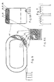
Fig. 2 und 2a zeigen einen Ausschnitt einer Aufsicht und einen Querschnitt einer Magnet-Decke. Diese besteht aus kleinen Permanentmagneten (PM). Diese können unterschiedliche Größen und Gestalt haben. Die Zahl der Magnete hängt von der Größe der Decke ab. Sie sind in einer textilen Gewebehülle (SA), z.B. aus Leinen, nebeneinander gehalten, wobei zwischen ihnen elastisches Füllmaterial (RF), z.B. aus Gummi, eingelagert, das mit der Gewebehülle (SA) vernäht ist, und zwar entlang den Randern der Magnete, wie die gestrichelt gezeichnete Naht (SE) zeigt. Dieser Aufbau der Magnet-Decke hat eine Rechteckraster-Struktur. Alle Magnete sind in gleicher Richtung orientiert, wie Fig. 2a zeigt, und ihre magnetische Achse steht senkrecht zur Erstreckung der Decke.2 and 2a show a section of a top view and a cross section of a magnetic blanket. This consists of small permanent magnets (PM). These can have different sizes and shapes. The number of magnets depends on the size of the blanket. They are in a textile fabric cover (SA), e.g. made of linen, held side by side, with elastic filling material (RF), e.g. made of rubber, which is sewn to the fabric cover (SA), along the edges of the magnets, as shown by the dashed seam (SE). This structure of the magnetic ceiling has a rectangular grid structure. All magnets are oriented in the same direction, as shown in Fig. 2a, and their magnetic axis is perpendicular to the extent of the ceiling.
Fig. 3 zeigt eine alternative Anordnung der Magnete (PM) in Form einer Magnet-Schürze, die mit vielen runden Magnetplättchen gefüllt ist, um die herum genäht ist. Die Zwischenräume zwischen ihnen ist mit Gummit (RF) gefüllt. Seitlich sind Bänder (BE) an der Schürze befestigt, die zu deren Befestigung an einem Patientenkörper dienen.Fig. 3 shows an alternative arrangement of the magnets (PM) in the form of a magnet apron, which is filled with many round magnetic plates, around which is sewn. The gaps between them are filled with gummit (RF). Bands (BE) are attached to the side of the apron, which are used to attach them to a patient's body.
Die Magnet-Decke oder -Schürze erzeugen die Mikromassage in dem elektromagnetischen Wechselfeld. Wird dieses eingeschaltet, so oszillieren die Permanentmagnete durch die auftretenden wechselnden magnetisch-mechanischen Kräfte, die eine zarte Massage des abgedeckten Körperteils bewirken. Hierdurch wird eine wohltuende Wirkung auf lebendes Gewebe, z.B. eine verbesserte Mirkozirkulation und eine Schmerzbehebung, ausgeübt.The magnetic blanket or apron create the micro massage in the alternating electromagnetic field. When this is switched on, the permanent magnets oscillate due to the alternating magnetic-mechanical forces that cause a gentle massage of the covered part of the body. This has a beneficial effect on living tissue, e.g. improved microcirculation and pain relief.
Fig. 4 zeigt eine erste, flache, flexible Feldspulenanordnung der Vorrichtung, die in verschiedenen Größen herzustellen ist und aus vielen nebeneinanderliegenden, jeweils als rechteckige Spiralen aufgebauten, Leiterbündel-Abschnitten(FA, FB, FC) besteht. Eine Gesamtspulenanordnung ist vorzugsweise aus zwei getrennten Feldsoulandordnungen (FS1, FS2) gebildet.Fig. 4 shows a first, flat, flexible field coil arrangement of the device, which can be produced in different sizes and consists of many adjacent conductor bundle sections (FA, FB, FC), each constructed as rectangular spirals. An overall coil arrangement is preferably formed from two separate field coil arrangements (FS1, FS2).
Fig. 4a zeigt einen Querschnitt und Fig. 4 einen teilweise geöffneten Bereich der Feldspulenanordnung. Die flexiblen, isolierten Leiterbündel (W), die die Spulenabschnitte bilden, sind durch eine Ummantelung (LB) miteinander verbunden und nebeneinander gehalten, so daß sie die flache rechteckige Spirale bilden. Die drei Spulenabschnitte sind hintereinander geschaltet. Sie sind zwischen einer beidseitigen Textilabdeckung (LS) eingeschlossen und gehalten.4a shows a cross section and FIG. 4 shows a partially opened area of the field coil arrangement. The flexible, insulated conductor bundles (W) which form the coil sections are connected to one another by a sheath (LB) and are held next to one another so that they form the flat rectangular spiral. The three coil sections are connected in series. They are enclosed and held between a textile cover (LS) on both sides.
Vorteilhaft ist um die Textilabdeckung (LS) eine dünne Schicht aus Schaumstoff (SP) und eine Kunststoffabdeckung (SK) herumgelegt.A thin layer of foam (SP) and a plastic cover (SK) are advantageously placed around the textile cover (LS).
Die beiden Spulenanordnungen (FS1, FS2) werden so bestromt und übereinander oder nebeneinander angeordnet, daß sich ihre Magnetfelder addierend überlagern, wie Fig. 5 schematisch zeigt. Die Anschlüsse (A1, A2; B1, B2) sind an die Steckerbuchse (CO), Fig. 1, geführt.The two coil arrangements (FS1, FS2) are energized and arranged one above the other or next to one another such that their magnetic fields are superimposed, as shown in FIG. 5 schematically shows. The connections (A1, A2; B1, B2) are connected to the plug socket (CO), Fig. 1.
Fig. 6 zeigt eine hohl-zylindrische Feldspulenausgestaltung, bei der die beiden Spulenanordnungen (FS1', FS2') aus dem Litzenkabel (W) direkt aufeinander gelegt sind. Der innere Aufbau ist aus der teilweise geöffneten Darstellung, aus dem Querschnitt Fig. 6b und dem vergrößerten Querschnitt Fig. 6a zu ersehen. Die Kabel (W) sind mit einer Ummantelung (LB), z.B. aus Leinenband, versehen, die der Spule ihre hohlzylindrische oder hohl-flachzylindrische Form gibt und ihr eine Flexibilität verleiht. Die gesamte Zylinderspule ist mit einer Textilummantelung (LS), darauf einer Schaumstoff- oder Schwammschicht (SP) und mit einer Kunststoff- oder Naturstoffhülle (SK) umgeben. Die flexible Ausführung der Spule ist sehr praktisch in der Handhabung und beim Transport, da ihre Gestalt den Bedürfnissen im Einzelfall anpaßbar ist.6 shows a hollow cylindrical field coil configuration in which the two coil arrangements (FS1 ', FS2') from the stranded cable (W) are placed directly on top of one another. The internal structure can be seen from the partially opened representation, from the cross section Fig. 6b and the enlarged cross section Fig. 6a. The cables (W) are covered with a jacket (LB), e.g. made of linen tape, which gives the spool its hollow cylindrical or hollow flat cylindrical shape and gives it flexibility. The entire solenoid is surrounded by a textile covering (LS), on top of it a foam or sponge layer (SP) and with a plastic or natural material cover (SK). The flexible design of the coil is very practical to handle and transport, as its shape can be adapted to individual needs.
Fig. 7 zeigt das elektrische Anschlußschema und die additive Magnetfeldlage.Fig. 7 shows the electrical connection diagram and the additive magnetic field position.
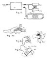
Fig. 8 zeigt eine Zusammenstellung des Impulsgenerators (IG) mit den wahlweisen anschließbaren Feldspulenanordnungen (FS1, FS2; MZ) und der Magnet-Decke (MD) oder der Magnetschürze (MS), rein schematisch.Fig. 8 shows a compilation of the pulse generator (IG) with the optional connectable field coil arrangements (FS1, FS2; MZ) and the magnetic cover (MD) or the magnetic apron (MS), purely schematically.
Fig. 9a zeigt die Anordnung einer Magnetschürze (MS) auf einem Patienten (P); die Magnetspule ist durch die flexiblen Anordnungen (FS1, FS2) gegeben, die auf die Magnetdecke (MD) aufgelegt ist.9a shows the arrangement of a magnetic apron (MS) on a patient (P); the magnetic coil is given by the flexible arrangements (FS1, FS2) that are placed on the magnetic blanket (MD).
Fig. 9b zeigt die Anordnung einer Bandage (BM) mit einer Magnetdecke (MD) eines Unterschenkels (US) und die umgebende Zylinderspule (MZ).Fig. 9b shows the arrangement of a bandage (BM) with a magnetic cover (MD) of a lower leg (US) and the surrounding Cylinder coil (MZ).
Fig. 9d zeigt eine lose Anordnung einer Magnetdecke (MD) auf einem Oberschenkel (OS); die Feldspule ist nicht dargestellt.9d shows a loose arrangement of a magnetic blanket (MD) on a thigh (OS); the field coil is not shown.
Fig. 9a bis 9d sind lediglich Anwendungs- und Ausgestaltungsbeispiele. Eine Anpassung an besondere Anwendungsfälle sowie an Tierkörper ist fachmännisch möglich. Statt der flexiblen Spulen, die besonders angenehm in der Anwendung sind, lassen sich auch feste Spulen verwenden. Die Spulen können auch in Kleidungsstücke eingearbeitet werden ebenso wie die Magnete. Die für die Massage-Schürze oder Massage-Decke verwandten Permanentmagnete lassen sich auch durch in sich starre, jedoch gegeneinander flexibel gehaltene Elektromagnete, die aus Spulen bestehen, verwenden, die mit Gleichstrom durchflossen sind; diese benötigen dann jedoch eine Betriebsbestromung.9a to 9d are only examples of use and design. An adaptation to special applications as well as to carcasses is professionally possible. Instead of the flexible coils, which are particularly pleasant to use, fixed coils can also be used. The coils can also be incorporated into clothing, as can the magnets. The permanent magnets used for the massage apron or massage blanket can also be used by means of electromagnets which are rigid in themselves, but which are flexible with respect to one another and which consist of coils and through which direct current flows; however, these then require operating current.
Eine weitere Ausgestaltung der Permanentmagnet-Decke oder -Schürze ist dadurch gegeben, daß sie aus einer gerastert geprägten Platte aus magnetisiertem Magnetgummi gebildet wird. Diese kann bedarfsweise mit einer textilen und/oder elastischen Hülle versehen sein. Die Abmessung der Magentplättchen ist bezüglich der Kantenlängen oder des Durchmessers im Bereich von 0,5 - 5 cm als günstig gefunden worden. Die Schwenkbewegung der Plättchen im Niederfrequenzfeld der Zylinderspule, deren Feld senkrecht zur Plättchenmagnetisierung orientiert ist, oder die Achsialbewegung der Plättchen, wenn deren Felder parallel zum Niederfrequenzfeld der elastischen Spulenanordnung gerichtet sind, wirkt zusammen mit den richtungsorientierten Gefäßwandungen der Blut- und Lympfgefäße wie eine Schlauchpumpe, nach Art einer Peristaltik, die Blutzirkulation fördernd und drainierend, wodurch auch im Anwendungsgebiet der Sportübungsvor- und nachbereitung vorteilhafte Wirkungen gefunden wurden.A further embodiment of the permanent magnet cover or apron is given by the fact that it is formed from a grid-embossed plate made of magnetized magnet rubber. If necessary, this can be provided with a textile and / or elastic covering. The dimensions of the magenta platelets have been found to be favorable with regard to the edge lengths or the diameter in the range from 0.5 to 5 cm. The pivotal movement of the platelets in the low-frequency field of the solenoid coil, the field of which is oriented perpendicular to the platelet magnetization, or the axial movement of the platelets if their fields are directed parallel to the low-frequency field of the elastic coil arrangement, works together with the direction-oriented vessel walls of the blood and lymph vessels Peristaltic peristaltic pump that promotes and drains blood circulation, which has also found beneficial effects in the area of sports exercise preparation and follow-up.
Claims (10)
- Treatment appliance for a human or animal body (P) or body part (US, OS), comprising a field coil arrangement (FS1, FS2; MZ) which is connected to a mains-operated, low-frequency power pulse current generator (IG) and in which a small magnetic plate (PM) is resiliently mounted, causing the plate to oscillate in the low-frequency magnetic field of the field coil arrangement (FS1, FS2; MZ),
characterised in that a plurality of small magnetic plates (MP) are held swivellable relative to one another in a magnetic cover (MD) or a magnetic apron (MS) shaped to fit the body and interposed between the magnetic plates (MP) is elastic material through which seams (SE) are sewn, and in that the field coil arrangement (FS1, FS2; MZ) consists of only one hollow cylindrical or flattened hollow cylindrical field coil (MZ) or of a plurality of coil sections (FA, FB, FC; FS1, FS2) which are arranged alongside one another and are linked to the single power pulse current generator (IG) so as to operate in the same direction. - Treatment appliance according to claim 1, characterised in that the coil sections (FA, FB, FC) are designed in spiral form and arranged alongside one another.
- Treatment appliance according to claim 1 or 2, characterised in that the field coil (MZ) or field coil sections (FA, FB, FC; FS1, FS2) consist of conductors (W) surrounded by a flexible sheath (LB) which fixes them in position.
- Treatment appliance according to claim 3, characterised in that the flexible sheath (LB) is surrounded by a textile layer (LS) on which a layer of foamed material (SP) rests, over which is laid a flexible envelope (SK) of plastic or natural material.
- Treatment appliance according to one of the preceding claims, characterised in that the power pulse current generator (IG) contains an oscillator (A) which at a definable repetition rate of 0.5 to 30 Hz emits sinusoidal or half-sinusoidal a.c. supply voltage at a frequency of, for example, 60 Hz.
- Treatment appliance according to one of the preceding claims 1 to 4, characterised in that the pulse generator (IG) contains an oscillator (A) which delivers square-wave voltage pulses at a definable frequency of 1 - 1000 Hz.
- Treatment appliance according to one of claims 5 or 6, characterised in that the output voltage of the pulse generator (IG) is adjustable.
- Treatment appliance according to claim 5, characterised in that the a.c. supply voltage is supplied, under the control of a triac (TRI) in phase with the first oscillator (A), to a variable transformer (TR1) the output of which passes via a diode (D) or a switch contact (SW2) to the output (CO) of the pulse generator (IG).
- Treatment appliance according to claim 6, characterised in that the a.c. supply voltage is supplied via a tapped transformer (TR1) to a rectifier (G) and the direct voltage there produced is sent, pulsed by electronic switch assemblies (TY), to the output (CO) of the pulse generator (IG), the switch assembly (TY) comprising two switch groups activated in chronologically conplementary manner by a second oscillator (IC2) via a square-wave generator (IC3).
- Treatment appliance according to claims 5 to 9, characterised in that the pulse generator (IG) contains the two oscillators (A, B), which can be switched on as required using an operating mode selector (SW3).
Priority Applications (1)
| Application Number | Priority Date | Filing Date | Title |
|---|---|---|---|
| AT89907138T ATE93716T1 (en) | 1988-06-22 | 1989-06-22 | MAGNETIC MASSAGE THERAPY DEVICE. |
Applications Claiming Priority (2)
| Application Number | Priority Date | Filing Date | Title |
|---|---|---|---|
| YU118988 | 1988-06-22 | ||
| YU1189/88 | 1988-06-22 |
Publications (2)
| Publication Number | Publication Date |
|---|---|
| EP0430951A1 EP0430951A1 (en) | 1991-06-12 |
| EP0430951B1 true EP0430951B1 (en) | 1993-09-01 |
Family
ID=25553153
Family Applications (1)
| Application Number | Title | Priority Date | Filing Date |
|---|---|---|---|
| EP89907138A Expired - Lifetime EP0430951B1 (en) | 1988-06-22 | 1989-06-22 | Magnetic massage-therapy device |
Country Status (6)
| Country | Link |
|---|---|
| EP (1) | EP0430951B1 (en) |
| JP (1) | JPH067871B2 (en) |
| KR (1) | KR950004325B1 (en) |
| AU (1) | AU623665B2 (en) |
| DE (2) | DE3919540A1 (en) |
| WO (1) | WO1989012433A1 (en) |
Cited By (1)
| Publication number | Priority date | Publication date | Assignee | Title |
|---|---|---|---|---|
| CN104856863A (en) * | 2015-04-01 | 2015-08-26 | 泉州市永茂电子科技有限公司 | Wear type physiotherapy equipment |
Families Citing this family (10)
| Publication number | Priority date | Publication date | Assignee | Title |
|---|---|---|---|---|
| DE4108437A1 (en) * | 1991-03-15 | 1992-09-17 | Rudolf Buschky | MAGNETIC BLANKET, PILLOWS, SHEETS OR THE LIKE |
| DE4116358A1 (en) * | 1991-05-18 | 1992-11-19 | Baermann Horst Rheinmagnet | METHOD AND DEVICE FOR GENERATING A MASSAGE EFFECT |
| DE4207054A1 (en) * | 1992-03-06 | 1993-09-09 | Zoltan Dr Med Molnar | DEVICE FOR MECHANICALLY INFLUENCING THE LUNG FOR Mucus Loosening |
| DE4317329C2 (en) * | 1993-05-25 | 1997-08-14 | Baktron Electronic Kft | Magnetic field system for therapeutic massage |
| AU645955B3 (en) * | 1993-05-26 | 1994-01-27 | Chuan-Hung Kao | Electric relaxer |
| WO2000078392A1 (en) * | 1999-06-18 | 2000-12-28 | Pulse Medical Co., Ltd. | Magnetic medical treatment device |
| JP2006296668A (en) * | 2005-04-19 | 2006-11-02 | Kagoshima Univ | Therapy apparatus |
| KR100846091B1 (en) * | 2006-12-28 | 2008-07-14 | 김휘영 | Band type magnetic curer |
| EP2810692A1 (en) * | 2013-06-05 | 2014-12-10 | Led S.p.A. | Device for magnetotherapy |
| US10245692B2 (en) | 2013-11-08 | 2019-04-02 | Makino Milling Machine Co., Ltd. | Chain-type tool magazine |
Family Cites Families (10)
| Publication number | Priority date | Publication date | Assignee | Title |
|---|---|---|---|---|
| GB283236A (en) * | 1926-07-09 | 1928-01-09 | Gaylord Wilshire | Improvements in electro-magnetic belts |
| FR2139720B1 (en) * | 1971-06-02 | 1974-03-22 | Miquel Joseph | |
| US3943912A (en) * | 1973-12-12 | 1976-03-16 | Takeo Nakayama | Medical treatment apparatus |
| JPS5623131B2 (en) * | 1974-12-26 | 1981-05-29 | ||
| DE2707574A1 (en) * | 1977-02-22 | 1978-08-24 | Goedde Geb Elsaesser Anna | Magnetic coil therapeutic apparatus - has single or double coil connected to programmed pulse shaper and oscillator with control system |
| DE2824698A1 (en) * | 1978-06-06 | 1979-12-13 | Wolfgang Dipl Phys Dr R Ludwig | MAGNETIC FIELD DEVICE AND ITS MEDICAL APPLICATION |
| JPS5955260A (en) * | 1982-09-21 | 1984-03-30 | 橋本 健 | Electromagnetic treating device |
| DE3335018A1 (en) * | 1983-09-28 | 1985-04-04 | Manfred 5429 Rettert Fichtner | Method for the control of a pulsating magnetic field and a device for conducting the method |
| HUT37044A (en) * | 1983-12-08 | 1985-11-28 | Ferenc Bordacs | Noninvazive therapeutic method and circuit arrangement for implementing this method |
| FR2585579A1 (en) * | 1985-08-01 | 1987-02-06 | Greffe Gerald | Electromagnetic cushion for treating skin disorders |
-
1989
- 1989-06-15 DE DE3919540A patent/DE3919540A1/en not_active Withdrawn
- 1989-06-22 JP JP1506973A patent/JPH067871B2/en not_active Expired - Lifetime
- 1989-06-22 DE DE89907138T patent/DE58905481D1/en not_active Expired - Fee Related
- 1989-06-22 WO PCT/EP1989/000689 patent/WO1989012433A1/en active IP Right Grant
- 1989-06-22 EP EP89907138A patent/EP0430951B1/en not_active Expired - Lifetime
- 1989-06-22 KR KR1019900700358A patent/KR950004325B1/en not_active IP Right Cessation
- 1989-06-22 AU AU38407/89A patent/AU623665B2/en not_active Ceased
Cited By (1)
| Publication number | Priority date | Publication date | Assignee | Title |
|---|---|---|---|---|
| CN104856863A (en) * | 2015-04-01 | 2015-08-26 | 泉州市永茂电子科技有限公司 | Wear type physiotherapy equipment |
Also Published As
| Publication number | Publication date |
|---|---|
| JPH03505291A (en) | 1991-11-21 |
| DE3919540A1 (en) | 1989-12-28 |
| JPH067871B2 (en) | 1994-02-02 |
| KR950004325B1 (en) | 1995-04-28 |
| KR900701238A (en) | 1990-12-01 |
| AU623665B2 (en) | 1992-05-21 |
| WO1989012433A1 (en) | 1989-12-28 |
| DE58905481D1 (en) | 1993-10-07 |
| AU3840789A (en) | 1990-01-12 |
| EP0430951A1 (en) | 1991-06-12 |
Similar Documents
| Publication | Publication Date | Title |
|---|---|---|
| DE2314573C2 (en) | Device for promoting healing processes | |
| DE69533232T2 (en) | MAGNETIC STIMULATOR FOR IRRITATION OF PERIPHERAL NERVES | |
| US5084003A (en) | Magnetic massage therapy device | |
| EP0430951B1 (en) | Magnetic massage-therapy device | |
| WO2010139376A1 (en) | Device and method for stimulating nerves by way of magnetic field pulses | |
| DE102017108084B4 (en) | Pulse source and method for magnetically inductive nerve stimulation | |
| DE3420326A1 (en) | METHOD AND DEVICE FOR TREATING LIVING TISSUE AND / OR LIVING CELLS THROUGH PULSING ELECTROMAGNETIC FIELDS | |
| DE2116869C2 (en) | Bone and biological tissue growth promotion appts. - uses flat coil for application of LF current from generator | |
| DE2822892A1 (en) | DEVICE FOR MAINTAINING THE NEGATIVE POTENTIAL OF HUMAN, ANIMAL AND VEGETABLE CELLS | |
| DE3512087A1 (en) | ELECTROMAGNETIC VIBRATION GENERATOR | |
| CH633177A5 (en) | ACUPUNKTURGERAET. | |
| EP1530982A1 (en) | Electrotherapy device | |
| DE4136374A1 (en) | Magneto-therapeutic bed for inducing sleep - has mattress contg. permanent magnet strips linked to EM field generator, and timer to regulate EM emissions. | |
| AT517737A1 (en) | Magnetic stimulation device | |
| DE2461516A1 (en) | ELECTROTHERAPEUTIC DEVICE WITH ALTERNATING CURRENT OF THE SOUND FREQUENCY BAND | |
| DE3236756A1 (en) | Stimulating current therapy unit | |
| DE20321629U1 (en) | Muscle stimulation in a plaster-immobilized limb | |
| DE19747608A1 (en) | Magnetisable or magnetic coil body for producing magnetic field for therapeutic application | |
| DE102008021574A1 (en) | Device for stimulating a healing process in the region of an implant | |
| CH275614A (en) | Short wave therapy electrode device. | |
| DE3716816C2 (en) | ||
| DE2821114A1 (en) | Alternating magnetic field medicinal therapy appts. - has rectangular core with coils on opposite sides generating magnetic poles at core ends | |
| DE3712150A1 (en) | Device for the magnetic field therapy of living beings | |
| DE3834849A1 (en) | Flexible magnetic field therapy mat | |
| AT401348B (en) | Coil arrangement for generating a travelling electromagnetic field for therapeutic purposes |
Legal Events
| Date | Code | Title | Description |
|---|---|---|---|
| PUAI | Public reference made under article 153(3) epc to a published international application that has entered the european phase |
Free format text: ORIGINAL CODE: 0009012 |
|
| 17P | Request for examination filed |
Effective date: 19900913 |
|
| AK | Designated contracting states |
Kind code of ref document: A1 Designated state(s): AT BE CH DE FR GB IT LI LU NL SE |
|
| 17Q | First examination report despatched |
Effective date: 19911127 |
|
| GRAA | (expected) grant |
Free format text: ORIGINAL CODE: 0009210 |
|
| AK | Designated contracting states |
Kind code of ref document: B1 Designated state(s): AT BE CH DE FR GB IT LI LU NL SE |
|
| REF | Corresponds to: |
Ref document number: 93716 Country of ref document: AT Date of ref document: 19930915 Kind code of ref document: T |
|
| GBT | Gb: translation of ep patent filed (gb section 77(6)(a)/1977) |
Effective date: 19930831 |
|
| REF | Corresponds to: |
Ref document number: 58905481 Country of ref document: DE Date of ref document: 19931007 |
|
| ITF | It: translation for a ep patent filed |
Owner name: DE DOMINICIS & MAYER S. |
|
| ET | Fr: translation filed | ||
| PLBE | No opposition filed within time limit |
Free format text: ORIGINAL CODE: 0009261 |
|
| STAA | Information on the status of an ep patent application or granted ep patent |
Free format text: STATUS: NO OPPOSITION FILED WITHIN TIME LIMIT |
|
| EPTA | Lu: last paid annual fee | ||
| 26N | No opposition filed | ||
| EAL | Se: european patent in force in sweden |
Ref document number: 89907138.5 |
|
| PGFP | Annual fee paid to national office [announced via postgrant information from national office to epo] |
Ref country code: NL Payment date: 20010614 Year of fee payment: 13 Ref country code: CH Payment date: 20010614 Year of fee payment: 13 |
|
| PGFP | Annual fee paid to national office [announced via postgrant information from national office to epo] |
Ref country code: GB Payment date: 20010615 Year of fee payment: 13 |
|
| PGFP | Annual fee paid to national office [announced via postgrant information from national office to epo] |
Ref country code: SE Payment date: 20010618 Year of fee payment: 13 |
|
| PGFP | Annual fee paid to national office [announced via postgrant information from national office to epo] |
Ref country code: LU Payment date: 20010619 Year of fee payment: 13 |
|
| PGFP | Annual fee paid to national office [announced via postgrant information from national office to epo] |
Ref country code: FR Payment date: 20010629 Year of fee payment: 13 |
|
| PGFP | Annual fee paid to national office [announced via postgrant information from national office to epo] |
Ref country code: AT Payment date: 20010630 Year of fee payment: 13 |
|
| PGFP | Annual fee paid to national office [announced via postgrant information from national office to epo] |
Ref country code: BE Payment date: 20010713 Year of fee payment: 13 |
|
| PGFP | Annual fee paid to national office [announced via postgrant information from national office to epo] |
Ref country code: DE Payment date: 20010726 Year of fee payment: 13 |
|
| REG | Reference to a national code |
Ref country code: GB Ref legal event code: IF02 |
|
| PG25 | Lapsed in a contracting state [announced via postgrant information from national office to epo] |
Ref country code: LU Free format text: LAPSE BECAUSE OF NON-PAYMENT OF DUE FEES Effective date: 20020622 Ref country code: GB Free format text: LAPSE BECAUSE OF NON-PAYMENT OF DUE FEES Effective date: 20020622 Ref country code: AT Free format text: LAPSE BECAUSE OF NON-PAYMENT OF DUE FEES Effective date: 20020622 |
|
| PG25 | Lapsed in a contracting state [announced via postgrant information from national office to epo] |
Ref country code: SE Free format text: LAPSE BECAUSE OF NON-PAYMENT OF DUE FEES Effective date: 20020623 |
|
| PG25 | Lapsed in a contracting state [announced via postgrant information from national office to epo] |
Ref country code: LI Free format text: LAPSE BECAUSE OF NON-PAYMENT OF DUE FEES Effective date: 20020630 Ref country code: CH Free format text: LAPSE BECAUSE OF NON-PAYMENT OF DUE FEES Effective date: 20020630 Ref country code: BE Free format text: LAPSE BECAUSE OF NON-PAYMENT OF DUE FEES Effective date: 20020630 |
|
| BERE | Be: lapsed |
Owner name: *SUSIC DRAGAN Effective date: 20020630 Owner name: *URBAN PAVLE Effective date: 20020630 |
|
| PG25 | Lapsed in a contracting state [announced via postgrant information from national office to epo] |
Ref country code: NL Free format text: LAPSE BECAUSE OF NON-PAYMENT OF DUE FEES Effective date: 20030101 Ref country code: DE Free format text: LAPSE BECAUSE OF NON-PAYMENT OF DUE FEES Effective date: 20030101 |
|
| EUG | Se: european patent has lapsed | ||
| GBPC | Gb: european patent ceased through non-payment of renewal fee |
Effective date: 20020622 |
|
| REG | Reference to a national code |
Ref country code: CH Ref legal event code: PL |
|
| PG25 | Lapsed in a contracting state [announced via postgrant information from national office to epo] |
Ref country code: FR Free format text: LAPSE BECAUSE OF NON-PAYMENT OF DUE FEES Effective date: 20030228 |
|
| NLV4 | Nl: lapsed or anulled due to non-payment of the annual fee |
Effective date: 20030101 |
|
| REG | Reference to a national code |
Ref country code: FR Ref legal event code: ST |
|
| PG25 | Lapsed in a contracting state [announced via postgrant information from national office to epo] |
Ref country code: IT Free format text: LAPSE BECAUSE OF NON-PAYMENT OF DUE FEES;WARNING: LAPSES OF ITALIAN PATENTS WITH EFFECTIVE DATE BEFORE 2007 MAY HAVE OCCURRED AT ANY TIME BEFORE 2007. THE CORRECT EFFECTIVE DATE MAY BE DIFFERENT FROM THE ONE RECORDED. Effective date: 20050622 |