EP0429907B1 - Optical biosensor - Google Patents
Optical biosensor Download PDFInfo
- Publication number
- EP0429907B1 EP0429907B1 EP90121347A EP90121347A EP0429907B1 EP 0429907 B1 EP0429907 B1 EP 0429907B1 EP 90121347 A EP90121347 A EP 90121347A EP 90121347 A EP90121347 A EP 90121347A EP 0429907 B1 EP0429907 B1 EP 0429907B1
- Authority
- EP
- European Patent Office
- Prior art keywords
- receptor
- dye
- film
- ligand
- biosensor according
- Prior art date
- Legal status (The legal status is an assumption and is not a legal conclusion. Google has not performed a legal analysis and makes no representation as to the accuracy of the status listed.)
- Expired - Lifetime
Links
Classifications
-
- C—CHEMISTRY; METALLURGY
- C07—ORGANIC CHEMISTRY
- C07D—HETEROCYCLIC COMPOUNDS
- C07D277/00—Heterocyclic compounds containing 1,3-thiazole or hydrogenated 1,3-thiazole rings
- C07D277/02—Heterocyclic compounds containing 1,3-thiazole or hydrogenated 1,3-thiazole rings not condensed with other rings
- C07D277/20—Heterocyclic compounds containing 1,3-thiazole or hydrogenated 1,3-thiazole rings not condensed with other rings having two or three double bonds between ring members or between ring members and non-ring members
- C07D277/32—Heterocyclic compounds containing 1,3-thiazole or hydrogenated 1,3-thiazole rings not condensed with other rings having two or three double bonds between ring members or between ring members and non-ring members with hetero atoms or with carbon atoms having three bonds to hetero atoms with at the most one bond to halogen, e.g. ester or nitrile radicals, directly attached to ring carbon atoms
- C07D277/56—Carbon atoms having three bonds to hetero atoms with at the most one bond to halogen
-
- C—CHEMISTRY; METALLURGY
- C07—ORGANIC CHEMISTRY
- C07D—HETEROCYCLIC COMPOUNDS
- C07D311/00—Heterocyclic compounds containing six-membered rings having one oxygen atom as the only hetero atom, condensed with other rings
- C07D311/02—Heterocyclic compounds containing six-membered rings having one oxygen atom as the only hetero atom, condensed with other rings ortho- or peri-condensed with carbocyclic rings or ring systems
- C07D311/04—Benzo[b]pyrans, not hydrogenated in the carbocyclic ring
- C07D311/06—Benzo[b]pyrans, not hydrogenated in the carbocyclic ring with oxygen or sulfur atoms directly attached in position 2
- C07D311/08—Benzo[b]pyrans, not hydrogenated in the carbocyclic ring with oxygen or sulfur atoms directly attached in position 2 not hydrogenated in the hetero ring
- C07D311/16—Benzo[b]pyrans, not hydrogenated in the carbocyclic ring with oxygen or sulfur atoms directly attached in position 2 not hydrogenated in the hetero ring substituted in position 7
-
- C—CHEMISTRY; METALLURGY
- C07—ORGANIC CHEMISTRY
- C07D—HETEROCYCLIC COMPOUNDS
- C07D417/00—Heterocyclic compounds containing two or more hetero rings, at least one ring having nitrogen and sulfur atoms as the only ring hetero atoms, not provided for by group C07D415/00
- C07D417/02—Heterocyclic compounds containing two or more hetero rings, at least one ring having nitrogen and sulfur atoms as the only ring hetero atoms, not provided for by group C07D415/00 containing two hetero rings
- C07D417/04—Heterocyclic compounds containing two or more hetero rings, at least one ring having nitrogen and sulfur atoms as the only ring hetero atoms, not provided for by group C07D415/00 containing two hetero rings directly linked by a ring-member-to-ring-member bond
-
- G—PHYSICS
- G01—MEASURING; TESTING
- G01N—INVESTIGATING OR ANALYSING MATERIALS BY DETERMINING THEIR CHEMICAL OR PHYSICAL PROPERTIES
- G01N21/00—Investigating or analysing materials by the use of optical means, i.e. using sub-millimetre waves, infrared, visible or ultraviolet light
- G01N21/62—Systems in which the material investigated is excited whereby it emits light or causes a change in wavelength of the incident light
- G01N21/63—Systems in which the material investigated is excited whereby it emits light or causes a change in wavelength of the incident light optically excited
- G01N21/64—Fluorescence; Phosphorescence
- G01N21/6428—Measuring fluorescence of fluorescent products of reactions or of fluorochrome labelled reactive substances, e.g. measuring quenching effects, using measuring "optrodes"
-
- G—PHYSICS
- G01—MEASURING; TESTING
- G01N—INVESTIGATING OR ANALYSING MATERIALS BY DETERMINING THEIR CHEMICAL OR PHYSICAL PROPERTIES
- G01N33/00—Investigating or analysing materials by specific methods not covered by groups G01N1/00 - G01N31/00
- G01N33/48—Biological material, e.g. blood, urine; Haemocytometers
- G01N33/50—Chemical analysis of biological material, e.g. blood, urine; Testing involving biospecific ligand binding methods; Immunological testing
- G01N33/53—Immunoassay; Biospecific binding assay; Materials therefor
- G01N33/536—Immunoassay; Biospecific binding assay; Materials therefor with immune complex formed in liquid phase
- G01N33/542—Immunoassay; Biospecific binding assay; Materials therefor with immune complex formed in liquid phase with steric inhibition or signal modification, e.g. fluorescent quenching
-
- G—PHYSICS
- G01—MEASURING; TESTING
- G01N—INVESTIGATING OR ANALYSING MATERIALS BY DETERMINING THEIR CHEMICAL OR PHYSICAL PROPERTIES
- G01N33/00—Investigating or analysing materials by specific methods not covered by groups G01N1/00 - G01N31/00
- G01N33/48—Biological material, e.g. blood, urine; Haemocytometers
- G01N33/50—Chemical analysis of biological material, e.g. blood, urine; Testing involving biospecific ligand binding methods; Immunological testing
- G01N33/53—Immunoassay; Biospecific binding assay; Materials therefor
- G01N33/543—Immunoassay; Biospecific binding assay; Materials therefor with an insoluble carrier for immobilising immunochemicals
- G01N33/54366—Apparatus specially adapted for solid-phase testing
- G01N33/54373—Apparatus specially adapted for solid-phase testing involving physiochemical end-point determination, e.g. wave-guides, FETS, gratings
-
- G—PHYSICS
- G01—MEASURING; TESTING
- G01N—INVESTIGATING OR ANALYSING MATERIALS BY DETERMINING THEIR CHEMICAL OR PHYSICAL PROPERTIES
- G01N33/00—Investigating or analysing materials by specific methods not covered by groups G01N1/00 - G01N31/00
- G01N33/48—Biological material, e.g. blood, urine; Haemocytometers
- G01N33/50—Chemical analysis of biological material, e.g. blood, urine; Testing involving biospecific ligand binding methods; Immunological testing
- G01N33/53—Immunoassay; Biospecific binding assay; Materials therefor
- G01N33/543—Immunoassay; Biospecific binding assay; Materials therefor with an insoluble carrier for immobilising immunochemicals
- G01N33/551—Immunoassay; Biospecific binding assay; Materials therefor with an insoluble carrier for immobilising immunochemicals the carrier being inorganic
- G01N33/552—Glass or silica
-
- G—PHYSICS
- G01—MEASURING; TESTING
- G01N—INVESTIGATING OR ANALYSING MATERIALS BY DETERMINING THEIR CHEMICAL OR PHYSICAL PROPERTIES
- G01N33/00—Investigating or analysing materials by specific methods not covered by groups G01N1/00 - G01N31/00
- G01N33/48—Biological material, e.g. blood, urine; Haemocytometers
- G01N33/50—Chemical analysis of biological material, e.g. blood, urine; Testing involving biospecific ligand binding methods; Immunological testing
- G01N33/53—Immunoassay; Biospecific binding assay; Materials therefor
- G01N33/543—Immunoassay; Biospecific binding assay; Materials therefor with an insoluble carrier for immobilising immunochemicals
- G01N33/551—Immunoassay; Biospecific binding assay; Materials therefor with an insoluble carrier for immobilising immunochemicals the carrier being inorganic
- G01N33/553—Metal or metal coated
-
- G—PHYSICS
- G01—MEASURING; TESTING
- G01N—INVESTIGATING OR ANALYSING MATERIALS BY DETERMINING THEIR CHEMICAL OR PHYSICAL PROPERTIES
- G01N33/00—Investigating or analysing materials by specific methods not covered by groups G01N1/00 - G01N31/00
- G01N33/48—Biological material, e.g. blood, urine; Haemocytometers
- G01N33/50—Chemical analysis of biological material, e.g. blood, urine; Testing involving biospecific ligand binding methods; Immunological testing
- G01N33/58—Chemical analysis of biological material, e.g. blood, urine; Testing involving biospecific ligand binding methods; Immunological testing involving labelled substances
- G01N33/582—Chemical analysis of biological material, e.g. blood, urine; Testing involving biospecific ligand binding methods; Immunological testing involving labelled substances with fluorescent label
-
- G—PHYSICS
- G01—MEASURING; TESTING
- G01N—INVESTIGATING OR ANALYSING MATERIALS BY DETERMINING THEIR CHEMICAL OR PHYSICAL PROPERTIES
- G01N21/00—Investigating or analysing materials by the use of optical means, i.e. using sub-millimetre waves, infrared, visible or ultraviolet light
- G01N21/62—Systems in which the material investigated is excited whereby it emits light or causes a change in wavelength of the incident light
- G01N21/63—Systems in which the material investigated is excited whereby it emits light or causes a change in wavelength of the incident light optically excited
- G01N21/64—Fluorescence; Phosphorescence
- G01N21/6428—Measuring fluorescence of fluorescent products of reactions or of fluorochrome labelled reactive substances, e.g. measuring quenching effects, using measuring "optrodes"
- G01N2021/6439—Measuring fluorescence of fluorescent products of reactions or of fluorochrome labelled reactive substances, e.g. measuring quenching effects, using measuring "optrodes" with indicators, stains, dyes, tags, labels, marks
- G01N2021/6441—Measuring fluorescence of fluorescent products of reactions or of fluorochrome labelled reactive substances, e.g. measuring quenching effects, using measuring "optrodes" with indicators, stains, dyes, tags, labels, marks with two or more labels
-
- Y—GENERAL TAGGING OF NEW TECHNOLOGICAL DEVELOPMENTS; GENERAL TAGGING OF CROSS-SECTIONAL TECHNOLOGIES SPANNING OVER SEVERAL SECTIONS OF THE IPC; TECHNICAL SUBJECTS COVERED BY FORMER USPC CROSS-REFERENCE ART COLLECTIONS [XRACs] AND DIGESTS
- Y10—TECHNICAL SUBJECTS COVERED BY FORMER USPC
- Y10S—TECHNICAL SUBJECTS COVERED BY FORMER USPC CROSS-REFERENCE ART COLLECTIONS [XRACs] AND DIGESTS
- Y10S435/00—Chemistry: molecular biology and microbiology
- Y10S435/968—High energy substrates, e.g. fluorescent, chemiluminescent, radioactive
-
- Y—GENERAL TAGGING OF NEW TECHNOLOGICAL DEVELOPMENTS; GENERAL TAGGING OF CROSS-SECTIONAL TECHNOLOGIES SPANNING OVER SEVERAL SECTIONS OF THE IPC; TECHNICAL SUBJECTS COVERED BY FORMER USPC CROSS-REFERENCE ART COLLECTIONS [XRACs] AND DIGESTS
- Y10—TECHNICAL SUBJECTS COVERED BY FORMER USPC
- Y10S—TECHNICAL SUBJECTS COVERED BY FORMER USPC CROSS-REFERENCE ART COLLECTIONS [XRACs] AND DIGESTS
- Y10S436/00—Chemistry: analytical and immunological testing
- Y10S436/80—Fluorescent dyes, e.g. rhodamine
-
- Y—GENERAL TAGGING OF NEW TECHNOLOGICAL DEVELOPMENTS; GENERAL TAGGING OF CROSS-SECTIONAL TECHNOLOGIES SPANNING OVER SEVERAL SECTIONS OF THE IPC; TECHNICAL SUBJECTS COVERED BY FORMER USPC CROSS-REFERENCE ART COLLECTIONS [XRACs] AND DIGESTS
- Y10—TECHNICAL SUBJECTS COVERED BY FORMER USPC
- Y10S—TECHNICAL SUBJECTS COVERED BY FORMER USPC CROSS-REFERENCE ART COLLECTIONS [XRACs] AND DIGESTS
- Y10S436/00—Chemistry: analytical and immunological testing
- Y10S436/805—Optical property
Definitions
- the present invention relates to an optical biosensor with a novel structure for a detection method for molecules which are labeled with a fluorescent dye for the detection of dissolved substances or dissolved analytes which, for example, behave like antigen and antibodies.
- This is a solid phase sensor with fluorescent dye, which allows an energy transfer process to a molecule to be detected and labeled with a second fluorescent dye.
- Immunoassays stand out as a sensitive detection method for the determination of very small amounts of organic substances. Immunoassay methods are generally based on the ability of a receptor molecule, for example an antibody, to To specifically recognize the structure and molecular organization of a ligand molecule, be it defined by non-polar and / or polar interactions, and to bind this molecule very specifically in this way.
- Immunoassays are carried out using various methods. These include the use of various labeling techniques, mostly radioactive, enzyme-linked and also fluorescent in nature (Methods in Enzymology, 74 (1981), 28-60).
- Some of these known immunoassay methods involve the use of fluorescent dye molecules F 1, which are capable of absorbing light of a wavelength ⁇ 1 and emitting light of a second, larger wavelength ⁇ 2.
- fluorescent dye molecules F 1 which are capable of absorbing light of a wavelength ⁇ 1 and emitting light of a second, larger wavelength ⁇ 2.
- F2 In the presence of another fluorescent dye molecule F2, under certain conditions after excitation of F1 by light of wavelength ⁇ 1, radiation-free energy transfer to F2 takes place, which in turn emits light of a third, even greater wavelength ⁇ 3.
- EP 150 905 describes an immunoassay that works in homogeneous solution, in which analyte or antigen is labeled with a fluorescent dye F 1 and the specifically binding antibody has been provided with a fluorescent dye F 2.
- F 1 fluorescent dye
- F 2 fluorescent dye
- one of the two marked binding partners is attached to a solid surface and the correspondingly specific binding partner is bound from a homogeneous solution.
- the specific binding is detected by a corresponding energy transfer using the Evanescent wave technology (Nature 320 (1986), 179-181).
- EP 174 744 proposes covalently binding several organic dye molecules to a "light-collecting" protein at the same time, i.e. there is an energy transfer of several organic dye molecules to only one acceptor molecule, namely a phycobiliprotein (allophycocyanin) in EP 174 744.
- This molecular system in turn is then proposed as a "marker" for other biological molecules.
- the method is limited by the dye: protein coupling ratio.
- a further disadvantage of the systems listed is that complementary systems have to be marked specifically and therefore cannot be used in a versatile manner.
- Another disadvantage of these systems, which are built in a heterogeneous phase is the special Evanescent wave technology used.
- the fixation of the specifically binding molecules to the Solid surface using a system of coupling component / antibody / antigen / antibody preparative very expensive.
- Another fundamental disadvantage of this solid-phase technology in immunoassays is the reproducible production of coatings on the test matrix with the reactants of the immune reaction.
- the reproducibility of the detection method is an essential quality feature.
- the present invention relates to a newly constructed sensor for a detection method of molecules marked with fluorescent dye for the detection of these dissolved substances or analytes by energy transfer with a simple fluorescence technique and increased sensitivity in the detection as well as versatile use for different tasks and reproducible production possibilities for layers bound to solid surfaces.
- all the disadvantages listed above are avoided at the same time.
- All carriers known to the person skilled in the art and suitable for LB technology such as glass, quartz glass, further glasses, such as Li-niobate, zinc selenide, porcelain, semiconductor materials, such as germanium, GaAs or silicon, and metals, are suitable as carriers.
- plastics such as polymethyl methacrylate, polycarbonate, polystyrene and other as well as metallized plastics.
- the solid support materials can also be surface-modified before coating, for example glass or quartz or silicon by pretreatment with trichloromethylsilane, dichlorodimethylsilane, trichloroctadecylsilane, hexamethyldisilazane or by plasma etching or plasma polymerization.
- the supports are preferably made of optionally surface-modified glass, quartz glass, silicon, plastic or a metallized plastic. Further preferred carriers are optically transparent. All carrier materials are further distinguished by a uniform surface, preferably by a flat surface.
- LB technology is understood below to mean a method for transferring monomolecular layers from a liquid (water) surface to a solid support using the Langmuir-Blodgett method.
- a solid support with an essentially smooth surface is immersed in a manner known per se through a compressed monomolecular film on the liquid surface, and this film is thereby transferred to the support.
- Multi-layer systems can be produced by repeated insertion and removal.
- the layer on the surface of the liquid can be exchanged after each dipping process, so that different sequences of layers on the carrier can be produced.
- the dipping in and out can be perpendicular or oblique to the surface of the liquid. Furthermore, according to the Langmuir-Schäfer technique, the carrier can also touch the liquid surface selectively or with an edge and then be folded onto the liquid surface. Finally, the carrier can also be lowered parallel to the liquid surface ("horizontal dipping").
- the transfer takes place at a temperature of 5-40 ° C, preferably at room temperature.
- These ordered LB layers can consist of low molecular weight and / or polymeric amphiphiles, preferably of polymeric amphiphiles, and contain covalently bonded fluorescent chromophores / dyes and / or amphiphilic fluorescent chromophores / dyes, which are referred to below as F 1.
- Suitable for F1 for an energy transfer take place.
- Förster distance as is necessary for the energy transfer described above, should be maintained between F1 and F2.
- the LB technique which allows a targeted molecular architecture, in particular in the dimensions of the region of interest of about 10-100 ⁇ .
- an emission of the fluorescent dye F2 with a wavelength ⁇ 3 can be detected, which serves as evidence for the binding of the molecule marked with F2 to the sensor surface, which is doped with F1 .
- the excitation with light of the wavelength ⁇ 1 can be such that F1 in the LB layer through the optically transparent carrier in transmission or by evanescent wave technology, if the optically transparent carrier acts as a light guide, or is excited by incident light irradiation.
- optical biosensor according to the invention can also be used to detect specific interactions without such special spatial conditions; this use is particularly important for checking the functionality, the measuring accuracy and other properties of the optical biosensor according to the invention.
- the sensor structure described in this way can not only detect an analyte present in solution, which is marked with fluorescent dye F2; the sensor structure can also be used to detect a non-fluorescence-labeled analyte in a competitive mode of operation.
- the specific binding sites of the functional molecules in the LB layer are saturated with fluorescence-labeled, complementarily binding molecules during the preparation of the sensor.
- Amphiphilic molecules are used to build LB layers, i.e. Molecules that have a hydrophilic end (a "head") and a hydrophobic end (a "tail”).
- Such amphiphilic molecules can be low molecular weight compounds with a molecular weight of up to about 2,000 g / mol.
- these low molecular weight amphiphiles can contain functional groups capable of polymerization or capable of polycondensation and polyaddition, so that after the LB layers have been built up from low molecular weight amphiphiles, these amphiphiles can be linked to high molecular weight compounds in a subsequent reaction in the LB layer. This subsequent reaction to form high molecular weight compounds is advantageous because LB layers made of polymeric amphiphiles have higher thermal and mechanical stabilities.
- LB films can be produced particularly elegantly from amphiphilic polymers by bringing the amphiphilic units together before they are then spread in a known manner on the liquid surface to form monomolecular layers.
- the use of such prepolymerized amphiphilic polymers thus avoids a disturbance in the orderly state once it has been produced by subsequent polymerization in the LB film.
- x and y are approximately the same.
- fluorescent dyes which are known to the person skilled in the art and can be used according to the invention are dyes of the following types: This list is only an example. Further amphiphilic fluorescent dyes are described in the monograph Physical Methods of Chemistry, Vol. 1, Part. 3B, pp. 577 ff, John Wiley, New York 1972. If you want to incorporate such amphiphilic fluorescent dyes in LB layers, a uniform distribution of the Dye throughout the layer. It is thus to be avoided that the transfer of individual layers, depending on the temperature (typically 5-40 °, preferably about 20 ° C.), takes place at such a thrust in which a coexistence area of the solid-analog and liquid-analog phase is passed through.
- the temperature typically 5-40 °, preferably about 20 ° C.
- amphiphilic fluorescent dye generally does not have the same solubility in the two phases and thus inhomogeneous layers are formed which are less suitable for sensor use.
- This phenomenon is known for LB layers made of low-molecular substances (Angew. Chem. 100 (1988), 750); this phenomenon has also been observed in polymerized phospholipids (Polymer Sci. 267 (1989), 97-107).
- M preferably assumes values of 0.4-0.6.
- LB layers produced in this way show layers which are homogeneous by light microscopy without interference both on water as a subphase and after transfer to a solid support and are particularly suitable for the biosensors according to the invention.
- a high sensitivity of the optical biosensor according to the invention can also be achieved if fluorescent dyes F 1 are used as donors in LB layers which, due to their special behavior, form aggregates with fluorescence spectroscopic properties which are very different from those of the monomeric dye and which are generally characterized by a correspondingly sharper and more intense absorption band and correspondingly sharper and more intense fluorescence emission band.
- aggregates are known to the person skilled in the art as J aggregates or disc aggregates (Physical Methods of Chemistry, Vol. 1, Part. 3B, p. 579, John Wiley, New York 1972).
- Fluorescent dyes which are capable of forming J aggregates in LB layers have been described in the literature mentioned above. Examples include: cyanine dyes and merocyanines.
- the link can be biological functional groups on LB layers on solid supports are carried out analogously to the immobilization methods known to those skilled in the art from biochemistry (Methods in Enzymology, Vol. 135 and Vol. 136 (1987)).
- Molecules provided with long alkyl chains are mentioned in DE-OS 3 546 150 in large selection as membrane anchor-active substance conjugates and can be incorporated into the LB film by co-spreading on the subphase.
- Glycolipids for example ceramides, may be mentioned as an example of such amphiphilic functional molecules.
- Other examples are antibody / antigen systems and complementary nucleotide sequences. A large number of such examples are known to the person skilled in the art (Angew. Chem. 100 (1988), 117-162).
- Crucial for increasing the sensitivity of the sensor system is the highest possible ratio F1: F2 within the "Förster radius" and thus a corresponding amplification of the fluorescence signal of a molecule labeled with F2 after binding to an F1-doped surface. It is therefore advantageous to introduce as many F 1 chromophores in the top LB layers, especially in the top four layers.
- the dye F 1 is arranged in at least one of the two upper layers.
- fluorescent dye concentrations below 1% are usually used in fluorescence spectroscopy to determine interactions between individuals
- Polymeric amphiphilic fluorescent dyes in particular show a lower tendency to self-extinction and excimer formation at a dye concentration of 0.1-25 mol%.
- the same concentration range also proves to be advantageous in the event that isolated chromophores are to be distributed uniformly in the LB layer.
- the association of chromophores is desirable. This association occurs preferably at dye concentrations above 25 mol% up to 100 mol% (without a polymer matrix).
- the optical biosensor according to the invention also has the advantage that, regardless of the functional molecules introduced into the layers of the solid phase, the dye F 1 required for the principle of energy transfer can be freely introduced into the LB layer in wide spectral ranges. This means that, on the one hand, the functional molecule does not have to be specifically labeled with F1 and, on the other hand, the spectral range of F1 can be optimally matched to the dye F2 used as a marker for energy transfer.
- the increase in the sensitivity of the fluorescence spectroscopic detection is achieved by introducing the highest possible dye concentration F 1 into the LB layer and thus several molecules F 1 in the necessary for the energy transfer to a molecule F 2 bound to the layer.
- This structure, the highest possible dye density F1 in the LB layer system next to the receptor, in contrast to the previously known, based on energy transfer detection methods allows a much cheaper use of this measuring principle and thus a significantly increased sensitivity, because a much higher per receptor molecule Number of dye molecules can be present than in the case of direct fluorescent labeling of the receptor molecule.
- the measuring principle is limited to layers up to about 100 ⁇ effective layer thickness, because underlying molecules F1 can no longer transfer their energy to the dye F2 that is too far away after excitation by light and would cause the signal to be detected, namely the light emission of the wavelength ⁇ 3 of the dye F2 excited by transfer predominantly interfere with its own fluorescence with the wavelength ⁇ 2 and unnecessarily reduce the sensitivity of the detection.
- the spin coating method which is widespread in thin-film technology, causes problems with minimum layer thicknesses of 200 to 500 ⁇ .
- the LB technique has the advantage that the composition of the layers can be adjusted in a very defined manner, which is of crucial importance for the production of reproducible surfaces for sensors.
- the donor dye F 1 and the active sites already mentioned for binding a biomolecule can also be located in different, superimposed LB layers.
- the total number of LB layers effective for the sensor principle ranges from 1 to 10.
- the optical biosensor according to the invention also includes mobile, fluorescent molecules which contain the dye component F2 and which are reversibly bound to the receptor molecules firmly anchored in the LB layer. Only in the simplest case, namely the determination of a self-fluorescent and thus acting as F2 analyte, this component is not necessary, since F2 and ligand are identical and represent the analyte. On the one hand, the binding sites of the receptors on the LB layer can be saturated by fluorescence-labeled derivatives or analogs of the analyte molecule, which can then be competitively displaced by the analyte in contact with the sample solution.
- a sandwich immunoassay is also possible in which a second type of receptor, for example antibodies, either on the complex between the first receptor and the analyte or on a molecular region of the analyte that is not involved in the binding to the first receptor, tie.
- a second type of receptor for example antibodies
- These methods of solid phase immunoassays are in principle state of the art and are described, for example, in the monograph P. Tijssen, Practice and Theory of Enzyme Immunoassays (RH Burdon, Ph.H. van Knippenberg, editor) Elsevier, Amsterdam 1985.
- a layer element prepared according to Example 4 was immersed in a solution of 10 ⁇ 7 mol / l fluorescein in phosphate buffer, pH 7.0, for 5 minutes. A fluorescence spectrum was recorded before and after the experiment. The emission spectrum shifted towards the maximum of fluorescein.
- the glass slide is briefly immersed in water and its surface carefully suctioned out after removal from the water. Two layers of cadmium arachidate were transferred to this support by the LB technique by immersing and removing the support.
- the following structure of the layer element is identical for monomers and disk aggregates.
- the film After compression of the film to a thrust of 20 mN / m and storage for 10 min. at constant thrust, the film became almost Transfer horizontal contact of the carrier with the monofilm on the carrier.
- the support was then completely immersed in the water, the remaining film of the dye was removed, and a monofilm of stearic acid was formed by spreading a 10 -3 m solution in chloroform and compressing to 20 mN / m.
- the support was then covered with a layer of stearic acid by vertical immersion.
- the support was coated with a mixed layer of dioctadecyl-dimethyl-ammonium bromide and methyl stearate in a molar ratio of 1: 1 by almost horizontal contact and complete immersion of the support and under water with a cuvette body in a manner known to the person skilled in the art (see P.Fromherz, Biochim Biophys. Acta. 323 (1973) 326-334) assembled into a fluorescence cuvette.
- VIII analyte
- pH 7.0
- the fluorescence intensity of (VII) in the case of the disk aggregates is reduced as a function of the concentration of the analyte in the adjacent solution and the time after the contact has been made.
- the binding of the analyte (VIII) to the surface of the layer element can also be demonstrated by measuring the fluorescence of (VIII) at 510 nm.
- a direct excitation (emission of the analyte) is possible at 470 nm, while the excitation of (VII) and subsequent energy transfer leads to a maximum emission of the analyte if it takes place at 366 nm (monomers) or 402 nm (disc aggregates) .
- the ratio of the fluorescence intensities at 510 nm after indirect excitation and energy transfer (I VII ) and with direct excitation of the bound analyte (I A ) is the amplification factor and can be determined from the excitation spectrum of the emission at 510 nm.
- a layer element produced according to Example 4 was dripped with 50 ⁇ l of a solution of lectin concanavalin A (1 mg / ml) labeled with tetramethylrhodamine isothiocyanate (TRITC) and a second, untreated slide of the same size was pressed in such a way that the liquid was uniform and without air bubbles distributed on the Langmuir-Blodgett (LB) layer. After an hour of exposure, both supports were separated and the coated was washed three times with aqueous phosphate buffer, 10 mmol / l, pH 6.8. A fluorescence spectrum was then measured and compared with that of a layer element not treated with protein. One recognized an additional band of TRITC emissions. If two to six dye-free layers were applied over the dye-containing LB layer, the intensity of this band drops to zero depending on the layer thickness.
- TRITC tetramethylrhodamine isothiocyanate
- a layer element (donor dye) produced according to Example 4 was additionally coated first with two layers of the polymer (V), then with one layer of the polymer (V), to which a defined amount of an amphiphilic acceptor dye was admixed. The fluorescence was measured on this layer element. The limit concentration at which the fluorescence of this substance was just detectable was determined by varying the amount of acceptor dye. The following table shows these values for different systems: Donor dye Acceptor dye Limit concentration [10 ⁇ 15 mol / mm2] after 4a (C18 rhodamine) 3rd after 4b 0.3 after 4c 0.3 after 4c (C18 aminofluorescein) 3rd
- Example 4 a layer element was produced by transferring a mixed monofilm consisting of the compound of the formula (IIa) and succinimidyl stearate in a weight ratio of 95: 5. This was then a solution of unlabeled Concanavalin A (1 mg / ml, dissolved in 0.01 mol / l phosphate buffer pH 6.8 with 1 mmol / l CaCl2, 1 mmol / l MnCl2 and 0.01% Triton X-100 ) left to act for one hour at room temperature (see Example 6). The element was washed with 0.5 ml of the same buffer.
Landscapes
- Health & Medical Sciences (AREA)
- Chemical & Material Sciences (AREA)
- Life Sciences & Earth Sciences (AREA)
- Immunology (AREA)
- Engineering & Computer Science (AREA)
- Organic Chemistry (AREA)
- Biomedical Technology (AREA)
- Hematology (AREA)
- Molecular Biology (AREA)
- Urology & Nephrology (AREA)
- Physics & Mathematics (AREA)
- Pathology (AREA)
- Biochemistry (AREA)
- General Physics & Mathematics (AREA)
- General Health & Medical Sciences (AREA)
- Analytical Chemistry (AREA)
- Microbiology (AREA)
- Medicinal Chemistry (AREA)
- Food Science & Technology (AREA)
- Cell Biology (AREA)
- Biotechnology (AREA)
- Inorganic Chemistry (AREA)
- Optics & Photonics (AREA)
- Chemical Kinetics & Catalysis (AREA)
- Nuclear Medicine, Radiotherapy & Molecular Imaging (AREA)
- Investigating, Analyzing Materials By Fluorescence Or Luminescence (AREA)
- Investigating Or Analysing Materials By The Use Of Chemical Reactions (AREA)
- Investigating Or Analysing Biological Materials (AREA)
- Measurement Of The Respiration, Hearing Ability, Form, And Blood Characteristics Of Living Organisms (AREA)
- Holo Graphy (AREA)
- Measuring Or Testing Involving Enzymes Or Micro-Organisms (AREA)
- Investigating Or Analysing Materials By Optical Means (AREA)
Abstract
Description
Die vorliegende Erfindung betrifft einen optischen Biosensor mit einem neuartigen Aufbau für eine Detektionsmethode für Moleküle, die mit einem Fluoreszenzfarbstoff markiert sind, zur Erkennung gelöster Substanzen oder gelöster Analyte, die sich beispielsweise wie Antigen und Antikörper verhalten. Es handelt sich hierbei um einen Festphasensensor mit Fluoreszenzfarbstoff, der einen Energietransferprozeß auf ein zu detektierendes, mit einem zweiten Fluoreszenzfarbstoff markiertes Molekül erlaubt.The present invention relates to an optical biosensor with a novel structure for a detection method for molecules which are labeled with a fluorescent dye for the detection of dissolved substances or dissolved analytes which, for example, behave like antigen and antibodies. This is a solid phase sensor with fluorescent dye, which allows an energy transfer process to a molecule to be detected and labeled with a second fluorescent dye.
Es gibt verschiedene Methoden, Analyten, wie Hormone, Enzyme, andere Proteine, Kohlenhydrate, Nucleinsäuren, pharmakologische Wirkstoffe, Toxine und andere, in flüssigen Proben biologischen Ursprungs nachzuweisen. Unter den bekannten Methoden ragen speziell Immunoassays als eine empfindliche Nachweismethode zur Bestimmung sehr kleiner Mengen organischer Substanzen heraus. Immunoassay-Methoden beruhen allgemein auf der Fähigkeit eines Rezeptormoleküls, beispielsweise eines Antikörpers, die Struktur und molekulare Organisation eines Ligandenmoleküls, sei sie durch unpolare und/oder polare Wechselwirkungen definiert, spezifisch zu erkennen und dieses Molekül auf derartige Weise ganz spezifisch zu binden.There are various methods for detecting analytes, such as hormones, enzymes, other proteins, carbohydrates, nucleic acids, pharmacological agents, toxins and others, in liquid samples of biological origin. Among the known methods, immunoassays stand out as a sensitive detection method for the determination of very small amounts of organic substances. Immunoassay methods are generally based on the ability of a receptor molecule, for example an antibody, to To specifically recognize the structure and molecular organization of a ligand molecule, be it defined by non-polar and / or polar interactions, and to bind this molecule very specifically in this way.
Immunoassays werden mit verschiedenen Methoden durchgeführt. Dazu zählen der Einsatz verschiedener Markierungstechniken, meist radioaktiver, enzymgekoppelter und auch fluoreszierender Natur (Methods in Enzymology, 74 (1981), 28-60).Immunoassays are carried out using various methods. These include the use of various labeling techniques, mostly radioactive, enzyme-linked and also fluorescent in nature (Methods in Enzymology, 74 (1981), 28-60).
Einige dieser bekannten Immunoassay-Methoden beinhalten die Verwendung von Fluoreszenzfarbstoff-Molekülen F₁, die in der Lage sind, Licht einer Wellenlänge λ₁ zu absorbieren und Licht einer zweiten, größeren Wellenlänge λ₂ zu emittieren. In Gegenwart eines anderen Fluoreszenzfarbstoff-Moleküls F₂ erfolgt unter bestimmten Bedingungen nach der Anregung von F₁ durch Licht der Wellenlänge λ₁ eine strahlungslose Energieübertragung auf F₂, der dann seinerseits Licht einer dritten, noch größeren Wellenlänge λ₃ emittiert.Some of these known immunoassay methods involve the use of fluorescent dye molecules F 1, which are capable of absorbing light of a wavelength λ 1 and emitting light of a second, larger wavelength λ 2. In the presence of another fluorescent dye molecule F₂, under certain conditions after excitation of F₁ by light of wavelength λ₁, radiation-free energy transfer to F₂ takes place, which in turn emits light of a third, even greater wavelength λ₃.
Dieses Prinzip des Energietransfers ist von Förster in der Theorie beschrieben worden und ist Anregung für vielerlei mögliche Anwendungen gewesen (Annual Reviews in Biochemistry 47 (1978), 819-846). Eine wichtige Eigenschaft dieses Energietransfers ist dabei seine Abstandsabhängigkeit. Die Wirksamkeit der Energieübertragung nach Förster wird durch den kritischen Radius Ro, nämlich den Abstand zwischen Donor und Akzeptor, beschrieben, bei dem der intermolekulare Energietransfer gleich wahrscheinlich wie die Summe aller anderen Desaktivierungsprozesse des Donors ist. Dieser Abstand beträgt etwa 50-100 Å.This principle of energy transfer has been described by Förster in theory and has been the inspiration for many possible applications (Annual Reviews in Biochemistry 47 (1978), 819-846). An important property of this energy transfer is its distance dependency. The effectiveness of energy transfer according to Förster is described by the critical radius R o , namely the distance between donor and acceptor, at which the intermolecular energy transfer is the same probably like the sum of all other donor deactivation processes. This distance is about 50-100 Å.
Es sind bereits Immunoassays beschrieben worden, die auf der Ausnützung des abstandsabhängigen Energietransfers beruhen. So wird in EP 150 905 ein in homogener Lösung arbeitender Immunoassay beschrieben, in dem Analyt bzw. Antigen mit einem Fluoreszenzfarbstoff F₁ markiert und der dazu spezifisch bindende Antikörper mit einem Fluoreszenzfarbstoff F₂ versehen wurde. Zum Nachweis der spezifischen Bindung und damit als analytische Methode wird die Tatsache genützt, daß beim Einstrahlen von Licht der Wellenlänge λ₁ eine Emission der Wellenlänge λ₃ nur dann beobachtet werden kann, wenn Analyt und Antikörper in ausreichender Konzentration in für eine Energieübertragung nach Förster genügend kleinem Abstand vorliegen. Dies ist nur dann der Fall, wenn Analyt und Antikörper eine spezifische Bindung eingegangen sind.Immunoassays have already been described which are based on the use of the distance-dependent energy transfer. For example, EP 150 905 describes an immunoassay that works in homogeneous solution, in which analyte or antigen is labeled with a fluorescent dye F 1 and the specifically binding antibody has been provided with a fluorescent dye F 2. To demonstrate the specific binding and thus as an analytical method, the fact is used that when light of wavelength λ₁ is emitted, an emission of wavelength λ₃ can only be observed if analyte and antibody are present in sufficient concentration in a sufficiently small distance for energy transfer according to Förster available. This is only the case if the analyte and antibody have a specific bond.
In einem anderen Beispiel wird einer der beiden markierten Bindungspartner an einer Festkörperoberfläche angebracht und der entsprechend spezifisch bindende Partner aus einer homogenen Lösung gebunden. Wieder erfolgt der Nachweis der spezifischen Bindung, wie oben bereits erläutert, durch einen entsprechenden Energietransfer mittels der Evanescent-wave-Technologie (Nature 320 (1986), 179-181).In another example, one of the two marked binding partners is attached to a solid surface and the correspondingly specific binding partner is bound from a homogeneous solution. Again, as already explained above, the specific binding is detected by a corresponding energy transfer using the Evanescent wave technology (Nature 320 (1986), 179-181).
Sowohl der hier erwähnte Energietransfer in homogener Lösung als auch der beschriebene Festphasen-Immunoassay mit Energietransfer haben prinzipiell den Nachteil, daß die spezifisch miteinander bindenden Moleküle jeweils mit einem der beiden notwendigen Fluoreszenzfarbstoffe F₁ bzw. F₂ markiert werden müssen und gemäß Nature 320 (1986), 179-181 ein Verhältnis F₁:F₂ von maximal 2:1 gestatten.Both the energy transfer mentioned here in homogeneous solution and the solid phase immunoassay with energy transfer described have the disadvantage in principle that the specifically binding molecules have to be labeled with one of the two necessary fluorescent dyes F 1 and F 2 and according to Nature 320 (1986), 179-181 allow a ratio F₁: F₂ of a maximum of 2: 1.
Es sind bereits Methoden beschrieben worden, mit denen die durch das Verhältnis der beiden Fluoreszenzfarbstoffe F₁ und F₂ limitierte Empfindlichkeit des fluoreszenzspektroskopischen Nachweises zu verbessern ist. So wird in EP 174 744 vorgeschlagen, mehrere organische Farbstoffmoleküle gleichzeitig an ein "lichtsammelndes" Protein kovalent zu binden, d.h. es erfolgt ein Energietransfer mehrerer organischer Farbstoffmoleküle an nur ein Akzeptormolekül, nämlich in EP 174 744 ein Phycobiliprotein (Allophycocyanin). Dieses Molekülsystem wiederum wird dann als ein "Marker" für andere biologische Moleküle vorgeschlagen. Die Methode wird begrenzt durch das Farbstoff:Protein-Kupplungsverhältnis.Methods have already been described with which the sensitivity of the fluorescence spectroscopic detection, which is limited by the ratio of the two fluorescent dyes F 1 and F 2, can be improved. For example, EP 174 744 proposes covalently binding several organic dye molecules to a "light-collecting" protein at the same time, i.e. there is an energy transfer of several organic dye molecules to only one acceptor molecule, namely a phycobiliprotein (allophycocyanin) in EP 174 744. This molecular system in turn is then proposed as a "marker" for other biological molecules. The method is limited by the dye: protein coupling ratio.
Weiterhin ist ein Nachteil der aufgeführten Systeme dadurch gegeben, daß komplementäre Systeme jeweils spezifisch markiert werden müssen und damit nicht vielseitig verwendet werden können. Ein weiterer Nachteil dieser in heterogener Phase aufgebauten Systeme ist die spezielle verwendete Evanescent-wave-Technik. Zudem ist die Fixierung der spezifisch bindenden Moleküle an die Festkörperoberfläche über ein System aus Kupplungskomponente/Antikörper/Antigen/Antikörper präparativ sehr aufwendig. Ein weiterer prinzipieller Nachteil dieser Festphasen-Technologie bei Immunoassays ist die reproduzierbare Herstellung von Beschichtungen der Testmatrix mit den Reaktanden der Immunreaktion. Für analytische Methoden ist jedoch neben Empfindlichkeit und Selektivität bezüglich einer Zielsubstanz die Reproduzierbarkeit der Detektionsmethode ein wesentliches Qualitätsmerkmal.A further disadvantage of the systems listed is that complementary systems have to be marked specifically and therefore cannot be used in a versatile manner. Another disadvantage of these systems, which are built in a heterogeneous phase, is the special Evanescent wave technology used. In addition, the fixation of the specifically binding molecules to the Solid surface using a system of coupling component / antibody / antigen / antibody preparative very expensive. Another fundamental disadvantage of this solid-phase technology in immunoassays is the reproducible production of coatings on the test matrix with the reactants of the immune reaction. For analytical methods, however, in addition to sensitivity and selectivity with regard to a target substance, the reproducibility of the detection method is an essential quality feature.
Die vorliegende Erfindung betrifft einen neuartig aufgebauten Sensor für eine Detektionsmethode von mit Fluoreszenzfarbstoff markierten Molekülen zur Erkennung dieser gelösten Substanzen oder Analyte durch Energietransfer mit einer einfachen Fluoreszenztechnik und gesteigerter Empfindlichkeit in der Detektion sowie vielseitiger Anwendung bei unterschiedlichen Aufgaben und reproduzierbarer Herstellungsmöglichkeit für an Festkörperoberflächen gebundene Schichten. Neben dem deutlichen Gewinn an Sensitivität werden alle oben aufgeführten Nachteile gleichzeitig vermieden.The present invention relates to a newly constructed sensor for a detection method of molecules marked with fluorescent dye for the detection of these dissolved substances or analytes by energy transfer with a simple fluorescence technique and increased sensitivity in the detection as well as versatile use for different tasks and reproducible production possibilities for layers bound to solid surfaces. In addition to the significant gain in sensitivity, all the disadvantages listed above are avoided at the same time.
Die Erfindung betrifft einen optischen Biosensor auf der Basis des Fluoreszenz-Energietransfers, bestehend aus
- a) einem festen Träger,
- b) einer auf a) angebrachten ein- oder mehrlagigen Langmuir-Blodgett(LB)-Schicht,
- c) mindestens einem Fluoreszenzfarbstoff F₁, der in mindestens einer der oberen 4 Lagen der LB-Schicht angeordnet ist,
- d) einem zur spezifischen Wechselwirkung befähigten Rezeptor-Molekül, das in oder an der obersten Lage der LB-Schicht gebunden oder angeordnet ist, und
- e) einem mobilen Fluoreszenzfarbstoff F₂, dessen Anregungsbande für einen Energietransfer ausreichend mit der Emissionsbande von F₁ überlappt und der
- e1) kovalent an einen Liganden gebunden ist, der an den Rezeptor bindungsfähig ist oder der
- e2) kovalent an einen anderen Rezeptor gebunden ist, der an den Komplex aus erstem Rezeptor und Ligand bindungsfähig ist,
wobei der Ligand bzw. der Ligand und der zweite Rezeptor zunächst nicht an die LB-Schicht gebunden sind.
- a) a solid support,
- b) a single or multi-layer Langmuir-Blodgett (LB) layer applied to a),
- c) at least one fluorescent dye F 1, which is arranged in at least one of the upper 4 layers of the LB layer,
- d) a receptor molecule capable of specific interaction, which is bound or arranged in or on the top layer of the LB layer, and
- e) a mobile fluorescent dye F₂, the excitation band for an energy transfer sufficiently overlaps with the emission band of F₁ and the
- e1) is covalently bound to a ligand which is bindable to the receptor or which
- e2) is covalently bound to another receptor which is capable of binding to the complex of the first receptor and ligand,
wherein the ligand or the ligand and the second receptor are initially not bound to the LB layer.
Optische Biosensoren nach den Ansprüchen 2-10 sind ebenfalls gegenstand der Anmeldung.Optical biosensors according to claims 2-10 are also the subject of the application.
Als Träger kommen alle dem Fachmann bekannten für die LB-Technik geeigneten Träger in Frage, wie Glas, Quarzglas, weitere Gläser, wie Li-niobat, Zinkselenid, Porzellan, Halbleitermaterialien, wie Germanium, GaAs oder Silizium sowie Metalle.All carriers known to the person skilled in the art and suitable for LB technology, such as glass, quartz glass, further glasses, such as Li-niobate, zinc selenide, porcelain, semiconductor materials, such as germanium, GaAs or silicon, and metals, are suitable as carriers.
Weiterhin sind geeignet: Kunststoffe, wie Polymethylmethacrylat, Polycarbonat, Polystyrol und andere sowie metallisierte Kunststoffe. Die festen Trägermaterialien können vor der Beschichtung auch oberflächenmodifiziert werden, beispielsweise Glas oder Quarz oder Silizium durch Vorbehandlung mit Trichlormethylsilan, Dichlordimethylsilan, Trichloroctadecylsilan, Hexamethyldisilazan oder durch Plasmaätzung bzw. Plasmapolymerisation. In bevorzugter Weise handelt es sich um Träger aus gegebenenfalls oberflächenmodifiziertem Glas, Quarzglas, Silizium, Kunststoff oder eine metallisierten Kunststoff. Weiterhin bevorzugte Träger sind optisch transparent. Alle Trägermaterialien sind weiterhin durch eine gleichmäßige Oberfläche, bevorzugt durch eine ebene Oberfläche, ausgezeichnet.Also suitable are: plastics, such as polymethyl methacrylate, polycarbonate, polystyrene and other as well as metallized plastics. The solid support materials can also be surface-modified before coating, for example glass or quartz or silicon by pretreatment with trichloromethylsilane, dichlorodimethylsilane, trichloroctadecylsilane, hexamethyldisilazane or by plasma etching or plasma polymerization. The supports are preferably made of optionally surface-modified glass, quartz glass, silicon, plastic or a metallized plastic. Further preferred carriers are optically transparent. All carrier materials are further distinguished by a uniform surface, preferably by a flat surface.
Auf solche Träger werden mit Hilfe der LB-Technik eine oder mehrere monomolekulare Schichten aufgebracht. Unter LB-Technik wird im folgenden ein Verfahren zur Übertragung von monomolekularen Schichten von einer Flüssigkeits-(Wasser-)oberfläche auf einen festen Träger nach dem Langmuir-Blodgett-Verfahren verstanden. Dazu taucht man in an sich bekannter Weise einen festen Träger mit im wesentlichen glatter Oberfläche durch einen komprimierten monomolekularen Film auf der Flüssigkeitsoberfläche und überträgt dadurch diesen Film auf den Träger.One or more monomolecular layers are applied to such carriers using the LB technique. LB technology is understood below to mean a method for transferring monomolecular layers from a liquid (water) surface to a solid support using the Langmuir-Blodgett method. For this purpose, a solid support with an essentially smooth surface is immersed in a manner known per se through a compressed monomolecular film on the liquid surface, and this film is thereby transferred to the support.
Durch mehrmaliges Ein- und Austauchen lassen sich hierdurch Mehrschichtsysteme herstellen. Die Schicht auf der Flüssigkeitsoberfläche kann nach jedem Tauchvorgang ausgetauscht werden, so daß unterschiedliche Folgen von Schichten auf dem Träger herstellbar sind.Multi-layer systems can be produced by repeated insertion and removal. The layer on the surface of the liquid can be exchanged after each dipping process, so that different sequences of layers on the carrier can be produced.
Das Ein- bzw. Austauchen kann senkrecht oder schräg zur Flüssigkeitsoberfläche erfolgen. Des weiteren kann gemäß der Langmuir-Schäfer-Technik der Träger auch punktuell oder mit einer Kante die Flüssigkeitsoberfläche berühren und dann auf die Flüssigkeitsoberfläche geklappt werden. Schließlich kann der Träger auch parallel auf die Flüssigkeitsoberfläche abgesenkt werden ("horizontal dipping").The dipping in and out can be perpendicular or oblique to the surface of the liquid. Furthermore, according to the Langmuir-Schäfer technique, the carrier can also touch the liquid surface selectively or with an edge and then be folded onto the liquid surface. Finally, the carrier can also be lowered parallel to the liquid surface ("horizontal dipping").
Die Übertragung findet bei einer Temperatur von 5-40°C, bevorzugt bei Raumtemperatur, statt.The transfer takes place at a temperature of 5-40 ° C, preferably at room temperature.
Diese geordneten LB-Schichten können aus niedermolekularen und/oder polymeren Amphiphilen, bevorzugt aus polymeren Amphiphilen, bestehen und kovalent gebundene Fluoreszenzchromophore/farbstoffe und/oder amphiphile Fluoreszenzchromophore/farbstoffe, die im folgenden als F₁ bezeichnet werden, enthalten.These ordered LB layers can consist of low molecular weight and / or polymeric amphiphiles, preferably of polymeric amphiphiles, and contain covalently bonded fluorescent chromophores / dyes and / or amphiphilic fluorescent chromophores / dyes, which are referred to below as F 1.
Weiterhin sind in diesen LB-Schichten funktionelle Moleküle als Rezeptoren, beispielsweise Glykolipide, Poly- und Oligonukleotide, Proteine oder Fragmente derselben, Haptene und andere, enthalten oder damit kovalent verknüpft. An diese Rezeptoren kann nun eine spezifische Bindung eines hierzu komplementären Moleküls (Ligand), wie eines Lectins, eines Antigens, eines Antikörpers und anderer, das mit einem zweiten, zu F₁ für einen Energietransfer passenden Fluoreszenzfarbstoff F₂ markiert ist, erfolgen. Im Falle der Bindung zwischen Rezeptor und Ligand soll zwischen F₁ und F₂ der sogenannte Förster-Abstand, wie er für den oben beschriebenen Energietransfer nötig ist, eingehalten werden. Diese Bedingung wird durch die Anwendung der LB-Technik gewährleistet, die eine gezielte molekulare Architektur, insbesondere in Dimensionen des hier interessierenden Bereiches von etwa 10-100 Å, gestattet. Wird das im Vorangegangenen beschriebene System nun mit Licht der Wellenlänge λ₁ angeregt, so läßt sich eine Emission des Fluoreszenzfarbstoffes F₂ mit einer Wellenlänge λ₃ detektieren, die als Nachweis für die Bindung des mit F₂ markierten Moleküls an der Sensoroberfläche, die mit F₁ dotiert ist, gilt. Die Anregung mit Licht der Wellenlänge λ₁ kann so erfolgen, daß F₁ in der LB-Schicht durch den optisch transparenten Träger hindurch in Transmission oder durch Evanescent-wave-Technik, wenn der optisch transparente Träger als Lichtleiter fungiert, oder aber durch Auflichtbestrahlung angeregt wird.Furthermore, functional molecules as receptors, for example glycolipids, poly- and oligonucleotides, proteins or fragments thereof, haptens and others, are contained in these LB layers or are covalently linked to them. A specific one can now be attached to these receptors Binding of a complementary molecule (ligand), such as a lectin, an antigen, an antibody and others, which is labeled with a second fluorescent dye F₂ suitable for F₁ for an energy transfer, take place. In the case of the bond between the receptor and ligand, the so-called Förster distance, as is necessary for the energy transfer described above, should be maintained between F₁ and F₂. This condition is guaranteed by the use of the LB technique, which allows a targeted molecular architecture, in particular in the dimensions of the region of interest of about 10-100 Å. If the system described above is now excited with light of the wavelength λ₁, an emission of the fluorescent dye F₂ with a wavelength λ₃ can be detected, which serves as evidence for the binding of the molecule marked with F₂ to the sensor surface, which is doped with F₁ . The excitation with light of the wavelength λ₁ can be such that F₁ in the LB layer through the optically transparent carrier in transmission or by evanescent wave technology, if the optically transparent carrier acts as a light guide, or is excited by incident light irradiation.
Die spezifische Wechselwirkung zwischen 2 zueinander komplementären Molekülen ist dem Fachmann auf dem Gebiet von biologisch, biochemisch und ganz besonders medizinisch (physiologisch) bedeutsamen Molekülen, etwa der oben genannten Art, bekannt. Solche Wechselwirkungen gehen letztendlich auf ionische Bindungen, Wasserstoffbrückenbindungen und van der Waalssche Kräfte zurück, die jedoch im Bereich der oben genannten Moleküle nur bei speziellen räumlichen (sterischen) Gegebenheiten wirksam werden (Schlüssel-Schloß-Theorie). Selbstverständlich kann der erfindungsgemäße Optische Biosensor auch zur Erkennung spezifischer Wechselwirkungen ohne solche speziellen räumlichen Gegebenheiten eingesetzt werden; dieser Einsatz ist insbesondere zur Überprüfung der Funktionstüchtigkeit, der Meßgenauigkeit und anderer Eigenschaften des erfindungsgemäßen Optischen Biosensors wichtig.The specific interaction between two mutually complementary molecules is known to the person skilled in the field of biologically, biochemically and very particularly medically (physiologically) important molecules, for example of the type mentioned above. Such interactions ultimately go to ionic bonds, hydrogen bonds and van der Waals forces, which, however, only become effective in the area of the above-mentioned molecules under special spatial (steric) conditions (key-lock theory). Of course, the optical biosensor according to the invention can also be used to detect specific interactions without such special spatial conditions; this use is particularly important for checking the functionality, the measuring accuracy and other properties of the optical biosensor according to the invention.
Der so beschriebene Sensoraufbau kann in dieser Funktion nicht nur einen in Lösung vorhandenen Analyten, der mit Fluoreszenzfarbstoff F₂ markiert ist, nachweisen; der Sensoraufbau kann auch genutzt werden, um in einer kompetitiven Funktionsweise einen nicht fluoreszenzmarkierten Analyten nachzuweisen. Hierzu werden bei der Präparation des Sensors die spezifisch bindenden Stellen der funktionellen Moleküle in der LB-Schicht mit fluoreszenzmarkierten, komplementär bindenden Molekülen abgesättigt. Man beobachtet dann bei Anregung mit Licht der Wellenlänge λ₁ eine maximale Fluoreszenz-Emission der Wellenlänge λ₃, deren Abnahme über einen zeitlichen Verlauf beobachtet werden kann, wenn bei Kontakt mit der zu untersuchenden Lösung die mit F₂ fluoreszenzmarkierten, komplementär bindenden Moleküle in einer Gleichgewichtsreaktion durch nicht fluoreszenzmarkierte, komplementär bindende Moleküle des gleichen Typs verdrängt werden.The sensor structure described in this way can not only detect an analyte present in solution, which is marked with fluorescent dye F₂; the sensor structure can also be used to detect a non-fluorescence-labeled analyte in a competitive mode of operation. For this purpose, the specific binding sites of the functional molecules in the LB layer are saturated with fluorescence-labeled, complementarily binding molecules during the preparation of the sensor. One then observes upon excitation with light of the wavelength λ₁ a maximum fluorescence emission of the wavelength λ₃, the decrease of which can be observed over a period of time if, upon contact with the solution to be investigated, the complementarily binding molecules marked with F₂ in an equilibrium reaction by not in an equilibrium reaction fluorescence-labeled, complementarily binding molecules of the same type are displaced.
Für den Aufbau von LB-Schichten verwendet man amphiphile Moleküle, d.h. Moleküle, die ein hydrophiles Ende (einen "Kopf") und ein hydrophobes Ende (einen "Schwanz") haben. Solche amphiphilen Moleküle können niedermolekulare Verbindungen mit einem Molekulargewicht von bis etwa 2.000 g/mol sein. In einer weiteren Variante können diese niedermolekularen Amphiphile polymerisationsfähige bzw. zur Polykondensation und Polyaddition befähigte funktionelle Gruppen enthalten, so daß nach dem Aufbau der LB-Schichten aus niedermolekularen Amphiphilen in einer nachträglichen Reaktion in der LB-Schicht diese Amphiphile zu hochmolekularen Verbindungen verknüpft werden können. Diese nachträgliche Reaktion zu hochmolekularen Verbindungen ist deshalb von Vorteil, weil LB-Schichten aus polymeren Amphiphilen höhere thermische und mechanische Stabilitäten aufweisen.Amphiphilic molecules are used to build LB layers, i.e. Molecules that have a hydrophilic end (a "head") and a hydrophobic end (a "tail"). Such amphiphilic molecules can be low molecular weight compounds with a molecular weight of up to about 2,000 g / mol. In a further variant, these low molecular weight amphiphiles can contain functional groups capable of polymerization or capable of polycondensation and polyaddition, so that after the LB layers have been built up from low molecular weight amphiphiles, these amphiphiles can be linked to high molecular weight compounds in a subsequent reaction in the LB layer. This subsequent reaction to form high molecular weight compounds is advantageous because LB layers made of polymeric amphiphiles have higher thermal and mechanical stabilities.
Besonders elegant lassen sich LB-Filme aus amphiphilen Polymeren herstellen, indem man die Verknüpfung der amphiphilen Einheiten herbeiführt, bevor diese dann in bekannter Weise auf der Flüssigkeitsoberfläche zu monomolekularen Schichten gespreitet werden. Die Verwendung solcher präpolymerisierter amphiphiler Polymere vermeidet so eine durch nachträgliche Polymerisation im LB-Film mögliche Störung des einmal hergestellten Ordnungszustandes.LB films can be produced particularly elegantly from amphiphilic polymers by bringing the amphiphilic units together before they are then spread in a known manner on the liquid surface to form monomolecular layers. The use of such prepolymerized amphiphilic polymers thus avoids a disturbance in the orderly state once it has been produced by subsequent polymerization in the LB film.
Beispiele für polymere Amphiphile, wie sie für den erfindungsgemäßen optischen Biosensor geeignet sind, sind α-Olefin-Maleinsäureanhydrid-Copolymere (British Polymer Journal 17 (1985), 368 ff; J. Macromol. Sci.-Phys. B 23 (1985), 549-573), Polyoctadecyl-methacrylat, Polyvinylstearat (J. Coll. Interface Sci. 86 (1982), 485), Polyvinylphospholipide (Angew. Chem. 100 (1988), 117-162), Cellulose-tristearat, amphiphile Polyamide (DE-OS 3 830 325) und Acrylamid-Copolymere. In bevorzugter Weise für die Herstellung stabiler LB-Schichten sind Polyurethane gemäß DE-OS 3 827 438 und Polyester gemäß DE-OS 3 830 862 geeignet. Unter den polymeren Amphiphilen sei weiterhin ganz besonders auf statistische Poly(alkylmethacrylat)-Copolymere des folgenden Typs verwiesen, die in ihrer Zusammensetzung breit variierbar sind:

in der
- R¹, R² und R³
- unabhängig voneinander Wasserstoff oder Methyl darstellen,
- R⁴
- geradkettiges C₁₄-C₂₂-Alkyl ist,
- R⁵
- das Wasserstoff-, Natrium- oder Kaliumion ist oder eine der Gruppen -CH₂-CH₂OH, -CH₂-CH₂-NH-tert.-butyl, -CH₂-CH₂-N(CH₃)₂,


- R⁶
- ein dem Fachmann bekannter Fluoreszenzchromophor ist, wie er weiter unten dargestellt ist, und
- x
- einen Wert von 0,2-1,
- y
- einen Wert von 0-0,8 und
- z
- einen Wert von 0-0,2 annimmt, wobei die Summe

in the
- R¹, R² and R³
- independently represent hydrogen or methyl,
- R⁴
- is straight-chain C₁₄-C₂₂ alkyl,
- R⁵
- is the hydrogen, sodium or potassium ion or one of the groups -CH₂-CH₂OH, -CH₂-CH₂-NH-tert-butyl, -CH₂-CH₂-N (CH₃) ₂,
- R⁶
- is a fluorescence chromophore known to those skilled in the art, as shown below, and
- x
- a value of 0.2-1,
- y
- a value of 0-0.8 and
- e.g.
- assumes a value of 0-0.2, the sum
In bevorzugter Weise sind x und y etwa gleich.Preferably x and y are approximately the same.
Beispiele für Polymere der Formel (I) sind die folgenden:

Bei den hier beispielhaft genannten Substanzen für LB-Mono- und Multischichten ist der Fluoreszenzchromophor an das amphiphile Polymer kovalent geknüpft. Wenngleich diese Anordnung die größtmögliche Stabilität der F₁ enthaltenden LB-Schichten ermöglicht, ist es aber auch möglich, F₁ enthaltende LB-Schichten durch Cospreiten eines amphiphilen Polymers mit amphiphilen Fluoreszenzfarbstoffen auf der Wasseroberfläche vor dem Beschichtungsvorgang zu erzielen. Als Beispiele für solche amphiphile Fluoreszenzfarbstoffe, die mit amphiphilen Polymeren, welche keine Chromophore enthalten, gemeinsam eingesetzt werden können, sind etwa Cyaninfarbstoffe der Typen

in denen
- X und Y
- unabhängig voneinander für Sauerstoff, Schwefel oder Selen oder C(CH₃)₂ stehen,
- R⁷
- Wasserstoff oder Methyl bedeutet und
- R⁸ und R⁹
- unabhängig voneinander für geradkettiges C₁-C₂₂-Alkyl stehen.
In the case of the substances for LB monolayers and multilayers mentioned here by way of example, the fluorescence chromophore is covalently linked to the amphiphilic polymer. Although this arrangement enables the greatest possible stability of the F₁-containing LB layers, it is also possible to achieve F₁-containing LB layers by co-spreading an amphiphilic polymer with amphiphilic fluorescent dyes on the water surface before the coating process. Examples of such amphiphilic fluorescent dyes that can be used together with amphiphilic polymers that do not contain chromophores are cyanine dyes of the types
in which
- X and Y
- independently of one another represent oxygen, sulfur or selenium or C (CH₃) ₂,
- R⁷
- Means hydrogen or methyl and
- R⁸ and R⁹
- independently represent straight-chain C₁-C₂₂ alkyl.
Weitere Beispiele für dem Fachmann grundsätzlich bekannte und erfindungsgemäß einsetzbare Fluoreszenzfarbstoffe sind Farbstoffe der folgenden Typen:


Diese Aufzählung ist nur beispielhaft. Weitere amphiphile Fluoreszenzfarbstoffe sind beschrieben in der Monographie Physical Methods of Chemistry, Vol. 1, Part. 3B, S. 577 ff, John Wiley, New York 1972. Will man solche amphiphile Fluoreszenzfarbstoffe in LB-Schichten einbringen, muß auf eine gleichmäßige Verteilung des Farbstoffs in der gesamten Schicht geachtet werden. So ist zu vermeiden, daß die Übertragung einzelner Schichten je nach Temperatur (typisch 5-40°, vorzugsweise etwa 20°C) bei einem solchen angelegten Schub erfolgt, bei dem ein Coexistenzbereich der festanalogen- und flüssiganalogen Phase durchlaufen wird. Dies ist wichtig, da der amphiphile Fluoreszenzfarbstoff in der Regel in den beiden Phasen nicht die gleiche Löslichkeit besitzt und so inhomogene, für die Sensoranwendung weniger geeignete Schichten gebildet werden. Diese Erscheinung ist bei LB-Schichten aus niedermolekularen Substanzen bekannt (Angew. Chem. 100 (1988), 750); auch bei polymerisierten Phospholipiden ist diese Erscheinung beobachtet worden (Polymer Sci. 267 (1989), 97-107).Further examples of fluorescent dyes which are known to the person skilled in the art and can be used according to the invention are dyes of the following types:
This list is only an example. Further amphiphilic fluorescent dyes are described in the monograph Physical Methods of Chemistry, Vol. 1, Part. 3B, pp. 577 ff, John Wiley, New York 1972. If you want to incorporate such amphiphilic fluorescent dyes in LB layers, a uniform distribution of the Dye throughout the layer. It is thus to be avoided that the transfer of individual layers, depending on the temperature (typically 5-40 °, preferably about 20 ° C.), takes place at such a thrust in which a coexistence area of the solid-analog and liquid-analog phase is passed through. This is important because the amphiphilic fluorescent dye generally does not have the same solubility in the two phases and thus inhomogeneous layers are formed which are less suitable for sensor use. This phenomenon is known for LB layers made of low-molecular substances (Angew. Chem. 100 (1988), 750); this phenomenon has also been observed in polymerized phospholipids (Polymer Sci. 267 (1989), 97-107).
Bei der Herstellung erfindungsgemäßer optischer Biosensoren wurde überraschenderweise gefunden, daß LB-Schichten aus Polymeren der Formel (II) beim Anlegen von Schüben bis zum Zusammenbruch der LB-Schicht bei >45 mN/m Schub nicht zur Ausbildung phasenseparierter Domänen neigen. Dies gilt neben Polymeren der Formel (II) auch für eine Mischung aus einem Polymer vom Typ der Formel (V) und einem Farbstoff, beispielsweise der Formel (IVa), wobei das Polymer vom Typ der Formel (V) als "Matrix" anzusehen ist, in welcher sich 0,1 bis 25 Mol-% des amphiphilen Farbstoffs aufhalten können, wobei beim Polymer die Wiederholungseinheiten zur Berechnung der Molprozente herangezogen werden:

worin
- m
- Werte von 0,25-1 und
- n
- Werte von 1-m annimmt.
wherein
- m
- Values from 0.25-1 and
- n
- Assumes values of 1-m.
In bevorzugter Weise nimmt m Werte von 0,4-0,6 an.M preferably assumes values of 0.4-0.6.
Derart hergestellte LB-Schichten zeigen sowohl auf Wasser als Subphase als auch nach dem Übertragen auf einen festen Träger lichtmikroskopisch homogene Schichten ohne Störungen und sind für die erfindungsgemäßen Biosensoren besonders geeignet.LB layers produced in this way show layers which are homogeneous by light microscopy without interference both on water as a subphase and after transfer to a solid support and are particularly suitable for the biosensors according to the invention.
Bei Systemen mit phasenseparierten Domänen kann aber auch eine hohe Empfindlichkeit des erfindungsgemäßen optischen Biosensors erreicht werden, wenn Fluoreszenzfarbstoffe F₁ als Donor in LB-Schichten verwendet werden, die aufgrund ihres speziellen Verhaltens Aggregate mit fluoreszenzspektroskopischen Eigenschaften bilden, die von denen des monomeren Farbstoffs sehr verschieden sind und die sich in der Regel durch eine entsprechend schärfere und intensivere Absorptionsbande und entsprechend schärfere und intensivere Fluoreszenz-Emissionsbande auszeichnen. Solche Aggregate sind dem Fachmann als J-Aggregate oder Scheibe-Aggregate bekannt (Physical Methods of Chemistry, Vol. 1, Part. 3B, S. 579, John Wiley, New York 1972). Mit dem speziellen Verhalten solcher J-Aggregate kann zum einen eine sehr hohe Farbstoffdichte F₁ in den LB-Schichten und zum anderen aufgrund der starken Absorption von Licht der Wellenlänge λ₁ eine hohe Energiedichte, die nach der Theorie von Förster auf entsprechende Moleküle F₂ übertragen werden kann, erreicht werden. Die geringe Halbwertsbreite der Emissionsbande bedeutet sowohl einen Verstärkungseffekt des Meßsignals, als auch eine Verminderung der Störstrahlung durch geringere Überlappung der Emissionen von F₁ mit F₂.In systems with phase-separated domains, however, a high sensitivity of the optical biosensor according to the invention can also be achieved if fluorescent dyes F 1 are used as donors in LB layers which, due to their special behavior, form aggregates with fluorescence spectroscopic properties which are very different from those of the monomeric dye and which are generally characterized by a correspondingly sharper and more intense absorption band and correspondingly sharper and more intense fluorescence emission band. Such aggregates are known to the person skilled in the art as J aggregates or disc aggregates (Physical Methods of Chemistry, Vol. 1, Part. 3B, p. 579, John Wiley, New York 1972). With the special behavior of such J-aggregates can on the one hand a very high dye density F₁ in the LB layers and on the other hand due to the strong absorption of light of the wavelength λ₁ a high energy density, which according to Theory by Förster can be transferred to corresponding molecules F₂ can be achieved. The small half-width of the emission band means both an amplification effect of the measurement signal and a reduction in the interference radiation due to less overlap of the emissions from F 1 to F 2.
Fluoreszenzfarbstoffe, die in LB-Schichten in der Lage sind, J-Aggregate zu bilden, sind in der obengenannten Literatur beschrieben worden. Beispielhaft seien genannt: Cyaninfarbstoffe und Merocyanine.Fluorescent dyes which are capable of forming J aggregates in LB layers have been described in the literature mentioned above. Examples include: cyanine dyes and merocyanines.
Der Einbau funktioneller Moleküle in die den Fluoreszenzfarbstoff F₁ enthaltende LB-Schicht kann auf unterschiedliche Art und Weise erfolgen:
- Das funktionelle Molekül kann kovalent, gegebenenfalls unter Verwendung von Spacer-Molekülen, an die LB-Schicht geknüpft sein, sei es von Beginn des Spreitungsvorganges auf der Wasseroberfläche an oder durch eine nachträgliche Kupplungsreaktion an die LB-Schicht entweder auf der Subphase oder nach Aufbringen der LB-Schicht auf einen festen Träger.
- Das funktionelle Molekül kann als Amphiphil mitgespreitet und so physikalisch mit "Anker" in die LB-Schicht eingebaut werden.
- The functional molecule can be covalently linked to the LB layer, if appropriate using spacer molecules, be it from the start of the spreading process on the water surface or by a subsequent coupling reaction to the LB layer either on the subphase or after application of the LB layer on a solid support.
- The functional molecule can be spread as an amphiphile and can thus be physically incorporated into the LB layer with an "anchor".
Für beide Einbauvarianten sind aus der Literatur Methoden bekannt. Beispielsweise kann die Verknüpfung biologischer funktioneller Gruppen an LB-Schichten auf feste Träger in analoger Weise zu den aus der Biochemie dem Fachmann bekannten Immobilisierungsmethoden erfolgen (Methods in Enzymology, Vol. 135 und Vol. 136 (1987)). Mit langen Alkylketten versehene Moleküle werden in DE-OS 3 546 150 als Membrananker-Wirkstoffkonjugate in großer Auswahl genannt und können durch Cospreiten auf der Subphase in den LB-Film eingebaut werden. Als ein Beispiel für solche amphiphile funktionelle Moleküle seien Glykolipide, beispielsweise Ceramide, genannt. Weitere Beispiele sind Antikörper/Antigen-Systeme sowie komplementäre Nucleotidsequenzen. Eine große Anzahl solcher Beispiele ist dem Fachmann bekannt (Angew. Chem. 100 (1988), 117-162).Methods for both installation variants are known from the literature. For example, the link can be biological functional groups on LB layers on solid supports are carried out analogously to the immobilization methods known to those skilled in the art from biochemistry (Methods in Enzymology, Vol. 135 and Vol. 136 (1987)). Molecules provided with long alkyl chains are mentioned in DE-OS 3 546 150 in large selection as membrane anchor-active substance conjugates and can be incorporated into the LB film by co-spreading on the subphase. Glycolipids, for example ceramides, may be mentioned as an example of such amphiphilic functional molecules. Other examples are antibody / antigen systems and complementary nucleotide sequences. A large number of such examples are known to the person skilled in the art (Angew. Chem. 100 (1988), 117-162).
Entscheidend für die Steigerung der Empfindlichkeit des Sensorsystems ist ein möglichst hohes Verhältnis F₁:F₂ innerhalb des "Förster-Radius" und damit eine entsprechende Verstärkung des Fluoreszenzsignals eines mit F₂ markierten Moleküls nach erfolgter Bindung an eine mit F₁ dotierte Oberfläche. Es ist demnach vorteilhaft, möglichst viele F₁-Chromophore in den obersten LB-Schichten, insbesondere in den obersten vier Lagen einzubringen. In besonders bevorzugter Weise ist der Farbstoff F₁ in mindestens einer der beiden oberen Lagen angeordnet.Crucial for increasing the sensitivity of the sensor system is the highest possible ratio F₁: F₂ within the "Förster radius" and thus a corresponding amplification of the fluorescence signal of a molecule labeled with F₂ after binding to an F₁-doped surface. It is therefore advantageous to introduce as many F 1 chromophores in the top LB layers, especially in the top four layers. In a particularly preferred manner, the dye F 1 is arranged in at least one of the two upper layers.
Wenngleich in der Fluoreszenzspektroskopie üblicherweise Konzentrationen an Fluoreszenzfarbstoff unter 1 % verwendet werden, um Wechselwirkungen zwischen den einzelnen Farbstoffmolekülen und damit Änderungen ihres Fluoreszenzverhaltens zu vermeiden, ist es im erfindungsgemäßen optischen Biosensor dennoch vorteilhaft, den Fluoreszenzfarbstoff F₁ in hohen Konzentrationen in die LB-Schichten einzubringen. Insbesondere polymere amphiphile Fluoreszenzfarbstoffe zeigen eine geringere Tendenz zur Eigenlöschung und Excimerenbildung bei Farbstoffkonzentration von 0,1-25 Mol-%. Der gleiche Konzentrationsbereich erweist sich auch als vorteilhaft für den Fall, daß isolierte Chromophore gleichmäßig in der LB-Schicht verteilt sein sollen. Im besonderen Fall der Scheibe-Aggregate ist hingegen die Assoziation von Chromophoren erwünscht. Diese Assoziation tritt bevorzugt bei Farbstoffkonzentrationen oberhalb von 25 Mol-% bis zu 100 Mol-% (ohne polymere Matrix) ein.Although fluorescent dye concentrations below 1% are usually used in fluorescence spectroscopy to determine interactions between individuals To avoid dye molecules and thus changes in their fluorescence behavior, it is nevertheless advantageous in the optical biosensor according to the invention to introduce the fluorescent dye F 1 in high concentrations into the LB layers. Polymeric amphiphilic fluorescent dyes in particular show a lower tendency to self-extinction and excimer formation at a dye concentration of 0.1-25 mol%. The same concentration range also proves to be advantageous in the event that isolated chromophores are to be distributed uniformly in the LB layer. In the special case of disc aggregates, however, the association of chromophores is desirable. This association occurs preferably at dye concentrations above 25 mol% up to 100 mol% (without a polymer matrix).
Der erfindungsgemäße optische Biosensor zeigt weiterhin den Vorteil, das unabhängig von den in die Schichten der festen Phase eingebrachten funktionellen Molekülen der für das Prinzip des Energietransfers erforderliche Farbstoff F₁ frei wählbar in weiten spektralen Bereichen in die LB-Schicht eingebracht werden kann. Dies bedeutet, daß zum einen das funktionelle Molekül nicht spezifisch mit F₁ markiert werden muß und zum anderen der spektrale Bereich von F₁ optimal für einen Energietransfer auf den als Marker verwendeten Farbstoff F₂ abgestimmt werden kann. Beispiele von Paaren sind:
FITC = Fluorescein-isothiocyanat.
FITC = fluorescein isothiocyanate.
Im erfindungsgemäßen optischen Biosensor wird wie beschrieben die Steigerung der Empfindlichkeit des fluoreszenzspektroskopischen Nachweises dadurch erreicht, das eine möglichst hohe Farbstoffkonzentration F₁ in die LB-Schicht eingebracht wird und somit mehrere Moleküle F₁ in den für den Energietransfer auf ein an die Schicht gebundenes Molekül F₂ notwendigen "Förster-Radius" gelangen. Dieser Aufbau, eine möglichst hohe Farbstoffdichte F₁ im LB-Schichtsystem neben dem Rezeptor einzubringen, erlaubt im Gegensatz zu den bisher bekannten, auf Energietransfer beruhenden Nachweismethoden eine viel günstigere Ausnutzung dieses Meßprinzips und damit eine deutlich erhöhte Empfindlichkeit, weil pro Rezeptor-Molekül eine viel höhere Anzahl an Farbstoffmolekülen vorhanden sein kann als bei einer direkten Fluoreszenzmarkierung des Rezeptor-Moleküls.In the optical biosensor according to the invention, as described, the increase in the sensitivity of the fluorescence spectroscopic detection is achieved by introducing the highest possible dye concentration F 1 into the LB layer and thus several molecules F 1 in the necessary for the energy transfer to a molecule F 2 bound to the layer. Ranger Radius ". This structure, the highest possible dye density F₁ in the LB layer system next to the receptor, in contrast to the previously known, based on energy transfer detection methods allows a much cheaper use of this measuring principle and thus a significantly increased sensitivity, because a much higher per receptor molecule Number of dye molecules can be present than in the case of direct fluorescent labeling of the receptor molecule.
Aus der Nutzung aller innerhalb des Förster-Radius von F₂ liegenden Farbstoffmoleküle F₁ folgt auch, das nicht nur die laterale Verteilung von F₁ innerhalb der obersten LB-Schichten von entscheidender Bedeutung ist, sondern auch die Konzentration von F₁ in den darunterliegenden Schichten. Aus diesem Grund beschränkt sich das Meßprinzip auf Schichten bis zu etwa 100 Å wirksamer Schichtdicke, denn darunterliegende Moleküle F₁ können nach Anregung durch Licht ihre Energie nicht mehr in ausreichendem Maße auf den dann zu weit entfernten Farbstoff F₂ übertragen und würden das zu detektierende Signal, nämlich die Lichtemission der Wellenlänge λ₃ des durch Transfer angeregten Farbstoffs F₂, durch ihre eigene Fluoreszenz mit der Wellenlänge λ₂ überwiegend stören und die Empfindlichkeit des Nachweises unnötig herabsetzen.From the use of all of the dye molecules F 1 lying within the Förster radius of F 2 also follows that not only the lateral distribution of F 1 within the top LB layers is of crucial importance, but also the concentration of F 1 in the layers below. For this reason, the measuring principle is limited to layers up to about 100 Å effective layer thickness, because underlying molecules F₁ can no longer transfer their energy to the dye F₂ that is too far away after excitation by light and would cause the signal to be detected, namely the light emission of the wavelength λ₃ of the dye F₂ excited by transfer predominantly interfere with its own fluorescence with the wavelength λ₂ and unnecessarily reduce the sensitivity of the detection.
Aus diesem Grund eignen sich für die Herstellung dünner Schichten (100 Å oder darunter), die F₁ enthalten, einzig die LB-Schicht-Technologie und die Chemisorption. Nämlich bereits die in der Dünnschichttechnologie verbreitete Methode des Spin-coating bereitet mit minimalen Schichtdicken von 200 bis 500 Å Probleme. Gegenüber dem Aufbringen dünner Schichten durch Chemisorption besitzt die LB-Technik den Vorteil, daß die Schichten in ihrer Zusammensetzung sehr definiert eingestellt werden können, was für die Herstellung reproduzierbarer Oberflächen für Sensoren von entscheidender Bedeutung ist.For this reason, only the LB layer technology and chemisorption are suitable for the production of thin layers (100 Å or below) which contain F₁. Namely, the spin coating method, which is widespread in thin-film technology, causes problems with minimum layer thicknesses of 200 to 500 Å. Compared to the application of thin layers by chemisorption, the LB technique has the advantage that the composition of the layers can be adjusted in a very defined manner, which is of crucial importance for the production of reproducible surfaces for sensors.
Der Donorfarbstoff F₁ und die bereits genannten aktiven Stellen zur Anbindung eines Biomoleküls können sich dabei auch in verschiedenen, übereinander liegenden LB-Schichten befinden. Die Gesamtzahl der für das Sensorprinzip wirksamen LB-Schichten bewegt sich im Zahlenbereich von 1 bis 10.The donor dye F 1 and the active sites already mentioned for binding a biomolecule can also be located in different, superimposed LB layers. The total number of LB layers effective for the sensor principle ranges from 1 to 10.
Zum erfindungsgemäßen optischen Biosensor gehören weiterhin mobile, fluoreszierende Moleküle, die die Farbstoffkomponente F₂ enthalten und die an die fest in der LB-Schicht verankerten Rezeptormoleküle reversibel gebunden werden. Lediglich im einfachsten Fall, nämlich der Bestimmung eines selbstfluoreszierenden und damit als F₂ wirkenden Analyten, ist diese Komponente nicht erforderlich, da F₂ und Ligand identisch sind und den Analyten darstellen. Zum einen können die Bindungsstellen der Rezeptoren auf der LB-Schicht durch fluoreszenzmarkierte Derivate oder Analoga des Analytenmoleküls abgesättigt sein, die dann im Kontakt mit der Probenlösung vom Analyten kompetitiv verdrängt werden können. Zum anderen ist jedoch auch ein Sandwich-Immunoassay möglich, bei dem eine zweite Art von Rezeptoren, beispielsweise Antikörpern, entweder an den Komplex zwischen erstem Rezeptor und dem Analyten oder an einen Molekülbereich des Analyten, die an der Bindung zum ersten Rezeptor nicht beteiligt ist, binden. Diese Methoden der Festphasen-Immunoassays sind prinzipiell Stand der Technik und beispielsweise in der Monographie P. Tijssen, Practice and Theory of Enzyme Immunoassays (R.H. Burdon, Ph.H. van Knippenberg, Herausgeber) Elsevier, Amsterdam 1985, dargestellt.The optical biosensor according to the invention also includes mobile, fluorescent molecules which contain the dye component F₂ and which are reversibly bound to the receptor molecules firmly anchored in the LB layer. Only in the simplest case, namely the determination of a self-fluorescent and thus acting as F₂ analyte, this component is not necessary, since F₂ and ligand are identical and represent the analyte. On the one hand, the binding sites of the receptors on the LB layer can be saturated by fluorescence-labeled derivatives or analogs of the analyte molecule, which can then be competitively displaced by the analyte in contact with the sample solution. On the other hand, however, a sandwich immunoassay is also possible in which a second type of receptor, for example antibodies, either on the complex between the first receptor and the analyte or on a molecular region of the analyte that is not involved in the binding to the first receptor, tie. These methods of solid phase immunoassays are in principle state of the art and are described, for example, in the monograph P. Tijssen, Practice and Theory of Enzyme Immunoassays (RH Burdon, Ph.H. van Knippenberg, editor) Elsevier, Amsterdam 1985.
Zu 1,53 g (5 mmol) 7-Diethylamino-3-(p-aminophenyl)cumarin und 0,61 g (5 mmol) Triethylamin in 10 ml trockenem Chloroform wurden unter Eisbadkühlung 1,51 g (5 mmol) Octadecansäurechlorid in 5 ml trockenem Chloroform getropft. Man ließ eine Stunde bei 0-5°C und 5 Stunden bei Raumtemperatur nachrühren. Der Ansatz wurde zunächst mit verdünnter Natronlauge, zuletzt mit Wasser gewaschen. Das Rohprodukt wurde zweimal aus Chloroform mit Petrolether 60/70°C gefällt.
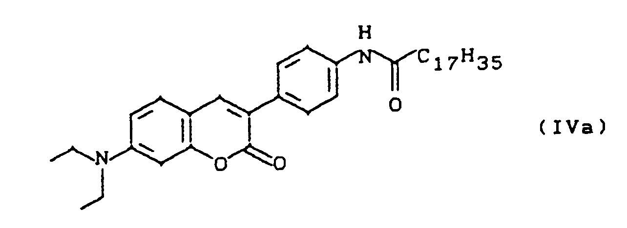
Es wurden 64 % der theoretischen Ausbeute des Produktes der obigen Formel mit einem Schmelzpunkt von 159°C erhalten.
¹H-NMR (CDCl₃, int. TMS): ![]()
3.42 (-CH₂CH₃); 2.35 (-COCH₂C₁₆H₃₃) 1.22 (-CH₂CH₃); 1,7-0,8 (-COCH₂C₁₆H₃₃).To 1.53 g (5 mmol) of 7-diethylamino-3- (p-aminophenyl) coumarin and 0.61 g (5 mmol) of triethylamine in 10 ml of dry chloroform were added 1.51 g (5 mmol) of octadecanoic acid chloride in 5 with ice bath cooling ml of dry chloroform. The mixture was left to stir for one hour at 0-5 ° C. and 5 hours at room temperature. The mixture was first washed with dilute sodium hydroxide solution and finally with water. The crude product was precipitated twice from chloroform with petroleum ether 60/70 ° C.
64% of the theoretical yield of the product of the above formula with a melting point of 159 ° C. were obtained.
1 H-NMR (CDCl₃, int. TMS): ![]()
3.42 (-C H ₂CH₃); 2.35 (-COC H ₂C₁₆H₃₃) 1.22 (-CH₂C H ₃); 1.7-0.8 (-COCH₂C₁₆ H ₃₃).
In analoger Weise wurden auch die weiter vorn aufgeführten Verbindungen IVb bis IVi hergestellt. Einige spektroskopische Daten sind in Tab. 1 zusammengestellt.
Zu 1,53 g (5 mmol) 7-Diethylamino-3-(p-aminophenyl)cumarin und 0,61 g (5 mmol) Triethylamin in 10 ml trockenem Chloroform wurden unter Eisbadkühlung 0,52 g (5 mmol) Methacrylsäurechlorid in 5 ml trockenem Chloroform getropft. Man ließ eine Stunde bei 0-5°C und 5 Stunden bei Raumtemperatur nachrühren. Der Ansatz wurde zunächst mit Natronlauge, zuletzt mit Wasser bis zur Salzfreiheit gewaschen und zur Trockne eingeengt.To 1.53 g (5 mmol) of 7-diethylamino-3- (p-aminophenyl) coumarin and 0.61 g (5 mmol) of triethylamine in 10 ml of dry chloroform were added 0.52 g (5 mmol) of methacrylic acid chloride in 5 with ice bath cooling ml of dry chloroform. The mixture was left to stir for one hour at 0-5 ° C. and 5 hours at room temperature. The mixture was first washed with sodium hydroxide solution, finally with water until salt-free and evaporated to dryness.
Ausbeute: 1,6 g entsprechend einer theoretischen Ausbeute von 86 % des Produktes der weiter unten (Tab. 2) aufgeführten Formel VIa mit einem Schmelzpunkt von 193-195°C.
¹H-NMR (CDCl₃, int. TMS): δ = 9.43 (NH), 7.77-6.49 (Multiplett, arom. Protonen);
5.86 und 5.47 (H₂C=); 3.44 (-CH₂CH₃); 2.04 (=C-CH₃); 1.22 (-CH₂CH₃).Yield: 1.6 g corresponding to a theoretical yield of 86% of the product of formula VIa listed below (Tab. 2) with a melting point of 193-195 ° C.
1 H-NMR (CDCl₃, int. TMS): δ = 9.43 (NH), 7.77-6.49 (multiplet, aromatic protons);
5.86 and 5.47 (H₂C =); 3.44 (-C H ₂CH₃); 2.04 (= C-CH₃); 1.22 (-CH₂C H ₃).
In analoger Weise wurden auch die ebenfalls in Tab. 2 aufgeführten Verbindungen VIb bis VIf hergestellt. Einige spektroskopische Daten sind in Tab. 2 zusammengestellt


6,77 g (20 mmol) Octadecylmethacrylat, 4,00 g (20 mmol) (2,2-Dimethyl-1,3-dioxolan-4-yl)-methylenmethacrylat und 1,51 g (4 mmol) des Farbstoffmonomeren des Beispiels 2 wurden in 90 ml absolutem Dioxan gelöst und nach Zugabe von 1,44 g (0,2 Mol-%) Azo-bis(isobutyronitril) unter Rühren auf 65-70°C erwärmt und 16 Stunden lang bei dieser Temperatur gehalten. Nach Abkühlen wurde aus der Reaktionslösung das Polymer durch Eintragen in Wasser ausgefällt. Das Polymer wurde durch zweimaliges Lösen in Chloroform und Fällen in Methanol gereinigt.6.77 g (20 mmol) octadecyl methacrylate, 4.00 g (20 mmol) (2,2-dimethyl-1,3-dioxolan-4-yl) methylene methacrylate and 1.51 g (4 mmol) the dye monomer of the example 2 were dissolved in 90 ml of absolute dioxane and, after adding 1.44 g (0.2 mol%) of azo-bis (isobutyronitrile), heated to 65-70 ° C. with stirring and kept at this temperature for 16 hours. After cooling, the polymer was precipitated from the reaction solution by adding it to water. The polymer was purified by dissolving twice in chloroform and precipitating in methanol.
Es wurden 3,93 g eines gelbgrünen Polymers erhalten, das durch Gelpermeationschromatographie in CH₂Cl₂ charakterisiert wurde. Gleichzeitige Detektion von Brechungsindex und UV-Spektroskopie lieferte identische Molekulargewichtsverteilungskurven, so das ein gleichmäßiger Einbau des Fluoreszenzfarbstoffs in das Polymer gewährleistet war. Gegenüber einer Polystyrol-Eichung ergaben sich rechnerisch Molmassenwerte Mn = 64.000 und Mw = 1.290.000 entsprechend einer Uneinheitlichkeit von 18.1.3.93 g of a yellow-green polymer were obtained, which was characterized by gel permeation chromatography in CH₂Cl₂. Simultaneous detection of refractive index and UV spectroscopy provided identical molecular weight distribution curves, so that a uniform incorporation of the fluorescent dye into the polymer was ensured. Compared to a polystyrene calibration, the calculated molar mass values M n = 64,000 and M w = 1,290,000 correspond to a non-uniformity of 18.1.
Nach dieser allgemeinen präparativen Vorschrift wurden alle Methacrylat-Copolymere hergestellt.All methacrylate copolymers were produced according to this general preparative procedure.
-
a) Polymerer Farbstoff
Ein durch Behandlung mit H₂O₂/H₂SO₄ gereinigter Objektträger aus Floatglas wurde bis zu einer Tiefe von 30 mm in die wäßrige Subphase einer Langmuir-Filmwaage (KSV 2200) bei 20°C eingetaucht. 150 µl einer Lösung der Verbindung der Formel (IIa) in Chloroform (1 mg/ml) wurden auf die Wasseroberfläche aufgespreitet. Nach dem Zusammenschieben der Schicht auf einen Oberflächendruck von 25 mN/m wurden durch sukzessives Aus- und Eintauchen (Tauchgeschwindigkeit: 10 mm/min) des Objektträgers drei monomolekulare Lagen Polymer übertragen. Die letzte Schicht wurde dabei beim Austauchen übertragen. Der Träger wurde anschließend an der Luft getrocknet. Eine Seite des Trägers wurde durch Reinigung mit Chloroform von der Farbstoffschicht befreit.a) Polymeric dye
A float glass slide cleaned by treatment with H₂O₂ / H₂SO₄ was immersed to a depth of 30 mm in the aqueous subphase of a Langmuir film balance (KSV 2200) at 20 ° C. 150 ul of a solution of the compound of formula (IIa) in chloroform (1 mg / ml) were spread on the water surface. After the layer had been pushed together to a surface pressure of 25 mN / m, three monomolecular layers of polymer were transferred by successively removing and immersing the slide (immersion speed: 10 mm / min). The last layer was transferred during the swap. The carrier was then air dried. One side of the support was stripped of the dye layer by cleaning with chloroform. - b) Polymer mit dispergiertem monomeren Farbstoff Anstelle der Lösung des farbstoffhaltigen Polymers der Formel (IIa) wurde eine Mischung des Polymers der Formel (V), 1 mg/ml, und des monomeren amphiphilen Farbstoffs der Formel (IIIb) mit X=Y=O, n=18, R⁷=H, R⁸=R⁹=C₁₈H₃₇, 1 mg/ml, im Verhältnis 19:1 verwendet.b) Polymer with dispersed monomeric dye Instead of the solution of the dye-containing polymer of the formula (IIa), a mixture of the polymer of the formula (V), 1 mg / ml, and the monomeric amphiphilic dye of the formula (IIIb) with X = Y = O , n = 18, R⁷ = H, R⁸ = R⁹ = C₁₈H₃₇, 1 mg / ml, used in a ratio of 19: 1.
-
c) Polymer mit dispergiertem Farbstoff, der Scheibe-Aggregate bildet.
Aufgezogen wurde eine Mischung des Polymers der Formel (V), 1 mg/ml, und des Farbstoffs der Formel (IIIb) mit X=Se, Y=S, R⁸=R⁹=C₁₈H₃₇, R²=CH₃, 1 mg/ml, im Gewichtsverhältnis von 1:1.c) polymer with dispersed dye that forms disk aggregates.
A mixture of the polymer of formula (V), 1 mg / ml, and the dye of formula (IIIb) with X = Se, Y = S, R⁸ = R⁹ = C₁₈H₃₇, R² = CH₃, 1 mg / ml, was drawn up in 1: 1 weight ratio.
Ein nach Beispiel 4 hergestelltes Schichtelement wurde in eine Lösung von 10⁻⁷ mol/l Fluorescein in Phosphatpuffer, pH 7.0, 5 min lang getaucht. Vor und nach dem Versuch wurde ein Fluoreszenzspektrum aufgenommen. Das Emissionsspektrum verschob sich zum Maximum von Fluorescein hin.A layer element prepared according to Example 4 was immersed in a solution of 10⁻⁷ mol / l fluorescein in phosphate buffer, pH 7.0, for 5 minutes. A fluorescence spectrum was recorded before and after the experiment. The emission spectrum shifted towards the maximum of fluorescein.
Ein durch Ultraschallbehandlung in einer wäßrigen Detergenslösung gereinigter und anschließend durch Ultraschallbehandlung mit reinem Wasser und weiterer Ultraschallbehandlung (5 min.) in ca. 5·10⁻² n NaOH sowie durch Abspritzen mit reinem Wasser unter einem Druck von 5 atm gespülter und danach getrockneter Glasträger wurde im Exsikkator durch Einwirkung von Hexamethyldisilazan hydrophobiert (30 min. bei 60°C im Wasserstrahlpumpenvakuum). Der Glasträger wird nach dieser Behandlung kurz in Wasser getaucht und seine Oberfläche nach dem Herausnehmen aus dem Wasser sorgfältig abgesaugt. Auf diesen Träger wurden nach der LB-Technik durch Ein- und Austauchen des Trägers zwei Schichten von Cadmiumarachidat übertragen.A glass carrier cleaned by ultrasound treatment in an aqueous detergent solution and then by ultrasound treatment with pure water and further ultrasound treatment (5 min.) In approx. 5 · 10⁻² n NaOH and by rinsing with pure water under a pressure of 5 atm and then dried glass carrier was made hydrophobic in the desiccator by the action of hexamethyldisilazane (30 min. at 60 ° C. in a water jet pump vacuum). After this treatment, the glass slide is briefly immersed in water and its surface carefully suctioned out after removal from the water. Two layers of cadmium arachidate were transferred to this support by the LB technique by immersing and removing the support.
Die darauf folgende Schicht des Fluoreszenzfarbstoffs (VII) = (IIIa) mit X = Y = O, R⁷ = H, R⁸ = R⁹ = C₁₈H₃₇ wurde in unterschiedlicher Organisation, i) als Monomere des Farbstoffs und ii) als Scheibe-Aggregate (J-Aggregate) des Farbstoffs präpariert und übertragen.
- i) Monomere des Farbstoffs (VII)
Ein monomolekularer Film auf Wasser wurde durch Spreiten einer Lösung erzeugt, die (VII), Methylarachidat, Arachinsäure und Hexadekan im molaren Verhältnis 1:2:18:20 in Chloroform enthält. - ii) Scheibe-Aggregate des Farbstoffs (VII)
Ein monomolekularer Film auf Wasser wurde durch Spreiten einer Lösung von (VII) und Hexadekan im molaren Verhältnis 1:1 in Chloroform erzeugt.
- i) monomers of the dye (VII)
A monomolecular film on water was created by spreading a solution containing (VII), methyl arachidate, arachidic acid and hexadecane in a molar ratio of 1: 2: 18: 20 in chloroform. - ii) disc aggregates of the dye (VII)
A monomolecular film on water was produced by spreading a solution of (VII) and hexadecane in a molar ratio of 1: 1 in chloroform.
Der folgende Aufbau des Schichtelements ist für Monomere und Scheibe-Aggregate identisch. Nach Kompression des Films auf einen Schub von 20 mN/m und Lagerung von 10 min. bei konstantem Schub wurde der Film durch nahezu horizontales Kontaktieren des Trägers mit dem Monofilm auf den Träger übertragen. Der Träger wurde dann vollständig in das Wasser eingetaucht, der restliche Film des Farbstoffs wurde entfernt, und ein Monofilm von Stearinsäure durch Spreiten einer 10⁻³ m Lösung in Chloroform und Kompression auf 20 mN/m gebildet. Der Träger wurde dann durch senkrechtes Austauchen mit einer Schicht von Stearinsäure bedeckt. Abschließend wurde der Träger mit einer gemischten Schicht von Dioktadecyl-dimethyl-ammoniumbromid und Methylstearat im Molverhältnis 1:1 durch nahezu horizontales Kontaktieren und vollständiges Eintauchen des Trägers beschichtet und unter Wasser mit einem Küvettenkörper in einer dem Fachmann bekannten Weise (siehe P.Fromherz, Biochim. Biophys. Acta. 323 (1973) 326-334) zu einer Fluoreszenzküvette zusammengebaut.The following structure of the layer element is identical for monomers and disk aggregates. After compression of the film to a thrust of 20 mN / m and storage for 10 min. at constant thrust, the film became almost Transfer horizontal contact of the carrier with the monofilm on the carrier. The support was then completely immersed in the water, the remaining film of the dye was removed, and a monofilm of stearic acid was formed by spreading a 10 -3 m solution in chloroform and compressing to 20 mN / m. The support was then covered with a layer of stearic acid by vertical immersion. Finally, the support was coated with a mixed layer of dioctadecyl-dimethyl-ammonium bromide and methyl stearate in a molar ratio of 1: 1 by almost horizontal contact and complete immersion of the support and under water with a cuvette body in a manner known to the person skilled in the art (see P.Fromherz, Biochim Biophys. Acta. 323 (1973) 326-334) assembled into a fluorescence cuvette.
Ein nach Beispiel 5b hergestelltes Schichtelement wurde durch Austausch des wäßrigen Mediums ohne Belüftung der Oberfläche des Schichtelements in Kontakt mit einer wäßrigen Lösung des Analyten (VIII) (Formel siehe unten) in einem 10⁻⁴ m Phosphatpuffer, pH = 7,0, gebracht. Infolge Bindung des Farbstoffs an die Oberfläche des Schichtelements wird die Fluoreszenzintensität von (VII) im Fall der Scheibe-Aggregate in Abhängigkeit von der Konzentration des Analyten in der angrenzenden Lösung und der Zeit nach Herstellen des Kontakts erniedrigt. Im Fall einer 10⁻⁷ m Lösung von (VIII) beträgt die Intensität der Emission bei 404 nm und Anregung bei 366 nm nach 90 min. 33 % der Intensität in Abwesenheit von (VIII), im Fall einer 10⁻¹⁰ m Lösung 85 %.A layer element produced according to Example 5b was brought into contact with an aqueous solution of the analyte (VIII) (formula see below) in a 10⁻⁴ m phosphate buffer, pH = 7.0, by exchanging the aqueous medium without aeration of the surface of the layer element. As a result of the dye being bound to the surface of the layer element, the fluorescence intensity of (VII) in the case of the disk aggregates is reduced as a function of the concentration of the analyte in the adjacent solution and the time after the contact has been made. In the case of a 10⁻⁷ m solution of (VIII) the Intensity of the emission at 404 nm and excitation at 366 nm after 90 min. 33% of the intensity in the absence of (VIII), in the case of a 10⁻¹⁰ m solution 85%.
Erwartungsgemäß wird eine deutliche Abstandsabhängigkeit dieses Löscheffekts beobachtet, wenn durch Einbau einer Doppelschicht von Cadmiumstearat zwischen der Stearinsäureschicht, die sich im Kontakt mit der Farbstoffschicht von der Oberfläche des Schichtelements vergrößert wird. Die Intensität der Emission des Scheibe-Aggregates bei 404 nm beträgt für eine 10⁻⁷ m Lösung von (VIII) dann 90 % der bei Abwesenheit von (VIII) beobachteten Intensität.As expected, a clear dependence on the distance of this quenching effect is observed if, by incorporating a double layer of cadmium stearate between the stearic acid layer, which increases in contact with the dye layer from the surface of the layer element. The intensity of the emission of the disk aggregate at 404 nm for a 10 μm solution of (VIII) is then 90% of the intensity observed in the absence of (VIII).
Die Bindung des Analyten (VIII) an die Oberfläche des Schichtelements läßt sich auch durch Messung der Fluoreszenz von (VIII) bei 510 nm nachweisen. Eine direkte Anregung (Emission des Analyten) ist bei 470 nm möglich, während die Anregung von (VII) und nachfolgende Energieübertragung zu einer maximalen Emission des Analyten führt, falls sie bei 366 nm (Monomere) bzw. 402 nm (Scheibe-Aggregate) erfolgt. Das Verhältnis der Fluoreszenzintensitäten bei 510 nm nach indirekter Anregung und Energietransfer (IVII) und bei direkter Anregung des gebundenen Analyten (IA) ist der Verstärkungsfaktor und kann aus dem Anregungsspektrum der Emission bei 510 nm bestimmt werden. Man findet fürThe binding of the analyte (VIII) to the surface of the layer element can also be demonstrated by measuring the fluorescence of (VIII) at 510 nm. A direct excitation (emission of the analyte) is possible at 470 nm, while the excitation of (VII) and subsequent energy transfer leads to a maximum emission of the analyte if it takes place at 366 nm (monomers) or 402 nm (disc aggregates) . The ratio of the fluorescence intensities at 510 nm after indirect excitation and energy transfer (I VII ) and with direct excitation of the bound analyte (I A ) is the amplification factor and can be determined from the excitation spectrum of the emission at 510 nm. One finds for
IVII/IA = 3 für 10⁻⁷ m Lösung von (VIII)
IVII/IA = 35 für 10⁻⁸ m Lösung von (VIII)I VII / I A = 3 for 10⁻⁷ m solution of (VIII)
I VII / I A = 35 for 10⁻⁸ m solution of (VIII)
IVII/IA = 380 für 10⁻⁸ m Lösung von (VIII)
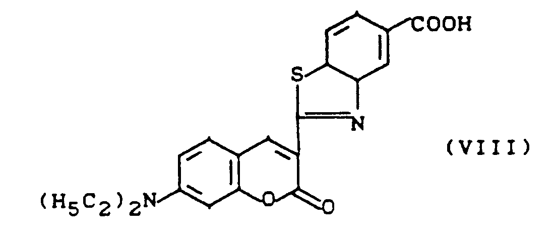
Ein nach Beispiel 4 hergestelltes Schichtelement wurde mit 50 µl einer Lösung von mit Tetramethylrhodamin-isothiocyanat (TRITC) markiertem Lectin Concanavalin A (1 mg/ml) betropft und ein zweiter, unbehandelter Objektträger gleicher Größe derart angepreßt, das sich die Flüssigkeit gleichmäßig und ohne Luftblasen auf der Langmuir-Blodgett(LB)-Schicht verteilte. Nach einer Stunde Einwirkungszeit wurden beide Träger getrennt und der beschichtete dreimal mit wäßrigem Phosphatpuffer, 10 mmol/l, pH 6.8, gewaschen. Anschließend wurde ein Fluoreszenzspektrum gemessen und mit dem eines nicht mit Protein behandelten Schichtelements verglichen. Man erkannte eine zusätzliche Bande der TRITC-Emission. Wurden über die farbstoffhaltige LB-Schicht zwei bis sechs Farbstoff-freie Lagen aufgebracht, so sinkt die Intensität dieser Bande in Abhängigkeit von der Schichtdicke bis auf Null.A layer element produced according to Example 4 was dripped with 50 μl of a solution of lectin concanavalin A (1 mg / ml) labeled with tetramethylrhodamine isothiocyanate (TRITC) and a second, untreated slide of the same size was pressed in such a way that the liquid was uniform and without air bubbles distributed on the Langmuir-Blodgett (LB) layer. After an hour of exposure, both supports were separated and the coated was washed three times with aqueous phosphate buffer, 10 mmol / l, pH 6.8. A fluorescence spectrum was then measured and compared with that of a layer element not treated with protein. One recognized an additional band of TRITC emissions. If two to six dye-free layers were applied over the dye-containing LB layer, the intensity of this band drops to zero depending on the layer thickness.
50 µl einer Lösung des Polymers (IIa), 1 mg/ml, in Chloroform wurden auf einen Objektträger gebracht. Mit Hilfe eines zweiten Objektträgers wurde die Farbstofflösung möglichst gleichmäßig auf dem ersten ausgestrichen. An diese Farbstofflage wurden dann, wie in Beispiel 6 beschrieben, 50 µl TRITC-ConA adsorbiert und die Fluoreszenz gemessen. Neben der sehr intensiven Bande von (IIa) ist die Fluoreszenz des TRITC nicht eindeutig nachzuweisen.50 µl of a solution of the polymer (IIa), 1 mg / ml, in chloroform was placed on a slide. With the help of a second slide, the dye solution was spread as evenly as possible on the first. As described in Example 6, 50 μl of TRITC-ConA were then adsorbed onto this dye layer and the fluorescence was measured. In addition to the very intense band of (IIa), the fluorescence of the TRITC cannot be clearly demonstrated.
0,0193 bis 0,244 mg des Polymers (IIa) wurden in 0,25 bis 1,5 ml Chloroform oder Dimethylformamid gelöst und mit Hilfe eines Spin-Coaters auf einen gereinigten Glasträger von 10 cm Durchmesser aufgegeben. Fluoreszenzmessungen der erhaltenen Glasplättchen zeigten eine sehr heterogene Verteilung der Farbstoffdichte, so daß keine Energietransfer-Messungen gemacht werden konnten.0.0193 to 0.244 mg of the polymer (IIa) were dissolved in 0.25 to 1.5 ml of chloroform or dimethylformamide and applied to a cleaned 10 cm diameter glass support using a spin coater. Fluorescence measurements The glass plates obtained showed a very heterogeneous distribution of the dye density, so that no energy transfer measurements could be made.
Ein nach Beispiel 4 hergestelltes Schichtelement (Donorfarbstoff) wurde zusätzlich zunächst mit zwei Lagen des Polymers (V), dann mit einer Lage des Polymers (V), dem eine definierte Menge eines amphiphilen Akzeptorfarbstoffes zugemischt ist, belegt. An diesem Schichtelement wurde die Fluoreszenz gemessen. Durch Variation der Akzeptorfarbstoffmenge wurde diejenige Grenzkonzentration festgestellt, bei der die Fluoreszenz dieser Substanz gerade noch detektierbar war. Die folgende Tabelle stellt diese Werte für verschiedene Systeme dar:
Analog zu Beispiel 4 wurde durch Übertragung eines gemischten Monofilms, bestehend aus der Verbindung der Formel (IIa) und Succinimidyl-stearat im Gewichtsverhältnis von 95:5, ein Schichtelement hergestellt. Auf dieses wurde anschließend eine Lösung von unmarkiertem Concanavalin A (1 mg/ml, gelöst in 0,01 mol/l Phosphatpuffer pH 6,8 mit 1 mmol/l CaCl₂, 1 mmol/l MnCl₂ und 0,01 % Triton X-100) eine Stunde lang bei Raumtemperatur einwirken gelassen (vergl. Beispiel 6). Das Element wurde mit 0,5 ml des gleichen Puffers gewaschen. Anschließend wurden 50 µl einer Lösung (0,1 mg/ml, gelöst im obigen Puffer) des TRITC-Mannosids (IX) aufgetragen und das Schichtelement erneut abgedeckt. In einem Kontrollversuch wurde anstelle von Con A die gleiche Menge Rinderserumalbumin verwendet.Analogously to Example 4, a layer element was produced by transferring a mixed monofilm consisting of the compound of the formula (IIa) and succinimidyl stearate in a weight ratio of 95: 5. This was then a solution of unlabeled Concanavalin A (1 mg / ml, dissolved in 0.01 mol / l phosphate buffer pH 6.8 with 1 mmol / l CaCl₂, 1 mmol / l MnCl₂ and 0.01% Triton X-100 ) left to act for one hour at room temperature (see Example 6). The element was washed with 0.5 ml of the same buffer. Then 50 μl of a solution (0.1 mg / ml, dissolved in the above buffer) of the TRITC-mannoside (IX) were applied and the layer element was covered again. In a control experiment, the same amount of bovine serum albumin was used instead of Con A.
Ein Vergleich der Fluoreszenzspektren beider Schichtelemente zeigt, daß bei Verwendung von Con A die Rhodamin-Emission bei 580 nm (aus IX) etwa fünffach stärker ist als die des Cumarins bei 495 nm (aus IIa). Bei Verwendung von Rinderserumalbumin ist nahezu keine (weniger als 1/20) Rhodamin-Emission im Vergleich zu der jetzt starken Cumarin-Emission zu beobachten.

Claims (10)
- Optical biosensor based on fluorescence energy transfer, consisting ofa) a solid support,b) a single-layer or multilayer Langmuir-Blodgett (LB) film attached to a),c) at least one fluorescent dye F₁ which is located in at least one of the top 4 layers of the LB film,d) a molecule (receptor) which is capable of specific interaction and which is bound or located in or on the topmost layer of the LB film, ande) a mobile fluorescent dye F₂ whose excitation band overlaps, sufficiently for an energy transfer, with the emission band of F₁ and whiche1) is covalently bonded to a ligand which is able to bind to the receptor, or whiche2) is covalently bonded to another receptor which is able to bind to the complex composed of the first receptor and ligand,
where the ligand or the ligand and the second receptor are initially not bound to the LB film. - Biosensor according to Claim 1, characterized in that the solid support used is composed of glass, quartz glass, Li niobate, zinc selenide, porcelain, semiconductor materials such as germanium, GaAs or silicon, a metal, a plastic or a metallized plastic, it being possible for the solid support to be surface-modified.
- Biosensor according to Claim 1, characterized in that the matrix of the LB film is a polymer.
- Biosensor according to Claim 1, characterized in that F₁ is covalently bonded to the matrix.
- Biosensor according to Claim 1, characterized in that the dye F₁ is spread together with an amphiphilic matrix, preferably in that the spreading together is with a dye F₁ which forms disc aggregates (J aggregates).
- Biosensor according to Claim 1, characterized in that the dye F₁ is located in at least one of the two upper layers of the LB film.
- Biosensor according to Claim 1, characterized in that the receptor molecule is attached covalently, preferably via a spacer molecule, to the topmost LB film.
- Biosensor according to Claim 1, characterized in that the receptor molecule is located onto the topmost film via a hydrophobic membrane anchor.
- Biosensor according to Claim 1, characterized in that a ligand which is labelled with fluorescent dye or is self-fluorescent binds to the binding sites of the receptor molecules, or in that an analyte which is not fluorescent-labelled competitively displaces a fluorescent-labelled ligand which is initially bound to the binding sites of the receptor molecules.
- Biosensor according to Claim 1, characterized in that a second receptor molecule which is labelled with the fluorescent dye F₂ and binds either specifically to the complex of receptor and analyte or to a different molecular region of the analyte than the receptor in the manner of a sandwich assay is added to the analyte solution.
Applications Claiming Priority (4)
| Application Number | Priority Date | Filing Date | Title |
|---|---|---|---|
| DE3938598 | 1989-11-21 | ||
| DE19893938598 DE3938598A1 (en) | 1989-11-21 | 1989-11-21 | Optical bio-sensor - based on fluorescent energy transfer between one dye incorporated in Langmuir-Blodgett film and marker dye |
| DE4013713 | 1990-04-28 | ||
| DE19904013713 DE4013713A1 (en) | 1990-04-28 | 1990-04-28 | Optical bio-sensor with Langmuir-blodgett film contg. fluorescent dye |
Publications (3)
| Publication Number | Publication Date |
|---|---|
| EP0429907A2 EP0429907A2 (en) | 1991-06-05 |
| EP0429907A3 EP0429907A3 (en) | 1991-10-16 |
| EP0429907B1 true EP0429907B1 (en) | 1994-06-01 |
Family
ID=25887278
Family Applications (1)
| Application Number | Title | Priority Date | Filing Date |
|---|---|---|---|
| EP90121347A Expired - Lifetime EP0429907B1 (en) | 1989-11-21 | 1990-11-08 | Optical biosensor |
Country Status (8)
| Country | Link |
|---|---|
| US (1) | US5194393A (en) |
| EP (1) | EP0429907B1 (en) |
| JP (1) | JPH03176662A (en) |
| AT (1) | ATE106566T1 (en) |
| CA (1) | CA2030244A1 (en) |
| DE (1) | DE59005928D1 (en) |
| DK (1) | DK0429907T3 (en) |
| FI (1) | FI98570C (en) |
Cited By (10)
| Publication number | Priority date | Publication date | Assignee | Title |
|---|---|---|---|---|
| EP0520262A1 (en) * | 1991-06-28 | 1992-12-30 | BASF Aktiengesellschaft | Chemical sensor |
| EP0552107A1 (en) * | 1992-01-17 | 1993-07-21 | The University Of Maryland At Baltimore | pH and pCO2, sensing by luminescent lifetimes and energy transfer |
| EP0561653A1 (en) * | 1992-01-17 | 1993-09-22 | The University Of Maryland At Baltimore | Determination and quantification of saccharides by luminescence lifetimes and energy transfer |
| EP0561239A1 (en) * | 1992-03-18 | 1993-09-22 | Bayer Ag | Optical solid-phase biosensor, with fluorescence labeled polyionic layers |
| EP0628819A2 (en) * | 1993-06-08 | 1994-12-14 | Bayer Ag | Coated carrier, method for manufacturing it and its use in immobilising biomolecules on the surfaces of solids |
| WO1996041166A2 (en) * | 1995-06-07 | 1996-12-19 | The Regents Of The University Of California | Detection of transmembrane potentials by optical methods |
| US5587472A (en) * | 1991-08-13 | 1996-12-24 | Bayer Corporation | Coumarin-labeled nucleoside 5'-triphosphates |
| WO1998000714A1 (en) * | 1996-06-28 | 1998-01-08 | Valtion Teknillinen Tutkimuskeskus | Fluorescent energy transfer ligand interaction assay on a lipid film |
| US6342379B1 (en) | 1995-06-07 | 2002-01-29 | The Regents Of The University Of California | Detection of transmembrane potentials by optical methods |
| US6596522B2 (en) | 1997-05-08 | 2003-07-22 | The Regents Of The University Of California | Detection of transmembrane potentials by optical methods |
Families Citing this family (103)
| Publication number | Priority date | Publication date | Assignee | Title |
|---|---|---|---|---|
| KR940004732A (en) * | 1992-08-07 | 1994-03-15 | 가나이 쯔또무 | Pattern formation method and thin film formation method used for pattern formation |
| US5552272A (en) * | 1993-06-10 | 1996-09-03 | Biostar, Inc. | Detection of an analyte by fluorescence using a thin film optical device |
| US6238931B1 (en) * | 1993-09-24 | 2001-05-29 | Biosite Diagnostics, Inc. | Fluorescence energy transfer in particles |
| US5824799A (en) * | 1993-09-24 | 1998-10-20 | Biosite Diagnostics Incorporated | Hybrid phthalocyanine derivatives and their uses |
| US6251687B1 (en) | 1993-09-24 | 2001-06-26 | Biosite Diagnostics, Inc. | Fluorescence energy transfer and intramolecular energy transfer in particles using novel compounds |
| US7322927B2 (en) | 1993-09-24 | 2008-01-29 | Biosite, Inc. | Hybrid phthalocyanine derivatives and their uses |
| US7083984B2 (en) | 1993-09-24 | 2006-08-01 | Biosite, Inc. | Hybrid phthalocyanine derivatives and their uses |
| US5496522A (en) * | 1994-02-07 | 1996-03-05 | Martin Marietta Energy Systems, Inc. | Biosensor and chemical sensor probes for calcium and other metal ions |
| US5577137A (en) * | 1995-02-22 | 1996-11-19 | American Research Corporation Of Virginia | Optical chemical sensor and method using same employing a multiplicity of fluorophores contained in the free volume of a polymeric optical waveguide or in pores of a ceramic waveguide |
| US5871915A (en) * | 1995-03-13 | 1999-02-16 | Research Development Corporation Of Japan | Method for detecting nucleic acid polymer |
| US5591407A (en) * | 1995-04-21 | 1997-01-07 | American Research Corporation Of Virginia | Laser diode sensor |
| US5690894A (en) * | 1995-05-23 | 1997-11-25 | The Regents Of The University Of California | High density array fabrication and readout method for a fiber optic biosensor |
| US5792621A (en) * | 1995-06-28 | 1998-08-11 | The United States Of America As Represented By The Administrator Of The National Aeronautics And Space Administration | Fiber-optic chemiluminescent biosensors for monitoring aqueous alcohols and other water quality parameters |
| DE19530078A1 (en) * | 1995-08-16 | 1997-02-20 | Bayer Ag | Optical solid phase biosensor based on streptavidin and biotin |
| US5837196A (en) * | 1996-01-26 | 1998-11-17 | The Regents Of The University Of California | High density array fabrication and readout method for a fiber optic biosensor |
| US5854863A (en) * | 1996-03-15 | 1998-12-29 | Erb; Judith | Surface treatment and light injection method and apparatus |
| US5671303A (en) * | 1996-04-17 | 1997-09-23 | Motorola, Inc. | Molecular detection apparatus and method using optical waveguide detection |
| EP2290364A1 (en) * | 1996-04-25 | 2011-03-02 | BioArray Solutions Ltd. | Light-controlled electrokinetic assembly of particles near surfaces |
| US6103535A (en) * | 1996-05-31 | 2000-08-15 | University Of Maryland | Optical fiber evanescent field excited fluorosensor and method of manufacture |
| DE19628002C1 (en) * | 1996-07-11 | 1997-12-18 | Inst Chemo Biosensorik | Device and method for carrying out fluorescence immunoassays |
| US6348322B1 (en) * | 1997-10-17 | 2002-02-19 | Duke University | Method of screening for specific binding interactions |
| US6475722B1 (en) * | 1997-12-03 | 2002-11-05 | Curagen Corporation | Surface treatments for DNA processing devices |
| US6289229B1 (en) | 1998-01-20 | 2001-09-11 | Scimed Life Systems, Inc. | Readable probe array for in vivo use |
| US6051437A (en) * | 1998-05-04 | 2000-04-18 | American Research Corporation Of Virginia | Optical chemical sensor based on multilayer self-assembled thin film sensors for aquaculture process control |
| US20050147534A1 (en) * | 1998-05-05 | 2005-07-07 | Massachusetts Institute Of Technology | Emissive sensors and devices incorporating these sensors |
| EP1080162B1 (en) * | 1998-05-05 | 2004-03-10 | Massachusetts Institute Of Technology | Emissive polymers and devices incorporating these polymers |
| US8198096B2 (en) * | 1998-05-05 | 2012-06-12 | Massachusetts Institute Of Technology | Emissive polymers and devices incorporating these polymers |
| WO1999067640A1 (en) | 1998-06-22 | 1999-12-29 | The Regents Of The University Of California | Triggered optical biosensor |
| US6277651B1 (en) | 1998-07-09 | 2001-08-21 | Calspan Srl Corporation | Diode laser electrochemical sensor for detecting chemical and biological analytes |
| US7166475B2 (en) * | 1999-02-26 | 2007-01-23 | Cyclacel Ltd. | Compositions and methods for monitoring the modification state of a pair of polypeptides |
| US7167615B1 (en) | 1999-11-05 | 2007-01-23 | Board Of Regents, The University Of Texas System | Resonant waveguide-grating filters and sensors and methods for making and using same |
| EP1122535A3 (en) * | 2000-01-31 | 2004-09-22 | The Penn State Research Foundation | Interrogation of changes in the contents of a sealed container |
| WO2001085997A1 (en) * | 2000-05-08 | 2001-11-15 | Qtl Biosystems Llc | Improvements to the fluorescent polymer-qtl approach to biosensing |
| US9709559B2 (en) | 2000-06-21 | 2017-07-18 | Bioarray Solutions, Ltd. | Multianalyte molecular analysis using application-specific random particle arrays |
| CA2413978C (en) | 2000-06-21 | 2008-12-16 | Bioarray Solutions, Ltd. | Multianalyte molecular analysis |
| DE60138196D1 (en) * | 2000-08-21 | 2009-05-14 | Massachusetts Inst Technology | COMPOSITION INCLUDING IPTYCEN POLYMERS WITH LARGE FREE INTERNAL VOLUME |
| US6706479B2 (en) | 2000-10-05 | 2004-03-16 | Virginia Tech Intellectual Properties, Inc. | Bio-chip, photoluminescent methods for identifying biological material, and apparatuses for use with such methods and bio-chips |
| US20030045005A1 (en) * | 2000-10-17 | 2003-03-06 | Michael Seul | Light-controlled electrokinetic assembly of particles near surfaces |
| AT410601B (en) * | 2000-12-29 | 2003-06-25 | Hoffmann La Roche | SENSOR FOR LUMINESCENCE-OPTICAL DETERMINATION OF ANALYTICAL AND REAGENT THAT WORKS ACCORDING TO THE FRET PRINCIPLE |
| WO2002054969A1 (en) * | 2001-01-10 | 2002-07-18 | Blood Cell Storage Inc. | System for growth, analysis, storage, validation and distribution of cells and tissues used for biomedical purposes |
| US7262063B2 (en) | 2001-06-21 | 2007-08-28 | Bio Array Solutions, Ltd. | Directed assembly of functional heterostructures |
| US7297311B2 (en) * | 2001-06-29 | 2007-11-20 | Sysmex Corporation | Automatic smear preparing apparatus and automatic sample analysis system having the same |
| US7723113B2 (en) * | 2001-08-20 | 2010-05-25 | Bayer Healthcare Llc | Packaging system for test sensors |
| IL161391A0 (en) | 2001-10-15 | 2004-09-27 | Bioarray Solutions Ltd | Multiplexed analysis of polymorphic loci by concurrent interrogation and enzyme-mediated detection |
| US7462325B2 (en) * | 2001-11-30 | 2008-12-09 | Nomadics, Inc. | Luminescent polymer particles |
| CA2419905C (en) | 2002-03-18 | 2016-01-05 | Bayer Healthcare, Llc | Storage cartridge for biosensors |
| US7041910B2 (en) * | 2002-07-15 | 2006-05-09 | Massachusetts Institute Of Technology | Emissive, high charge transport polymers |
| US7526114B2 (en) | 2002-11-15 | 2009-04-28 | Bioarray Solutions Ltd. | Analysis, secure access to, and transmission of array images |
| US20040121337A1 (en) * | 2002-12-19 | 2004-06-24 | Nomadics, Inc. | Luminescent polymers and methods of use thereof |
| WO2004081570A1 (en) * | 2003-03-13 | 2004-09-23 | Chengdu Kuachang Medical Industrial Limited | A chip matrix, a chip comprising the matrix and their preparation and application |
| US7364699B2 (en) * | 2003-06-18 | 2008-04-29 | Bayer Healthcare Llc | Containers for reading and handling diagnostic reagents and methods of using the same |
| US20040267299A1 (en) * | 2003-06-30 | 2004-12-30 | Kuriger Rex J. | Lancing devices and methods of using the same |
| WO2005029705A2 (en) | 2003-09-18 | 2005-03-31 | Bioarray Solutions, Ltd. | Number coding for identification of subtypes of coded types of solid phase carriers |
| WO2005031305A2 (en) | 2003-09-22 | 2005-04-07 | Bioarray Solutions, Ltd. | Surface immobilized polyelectrolyte with multiple functional groups capable of covalently bonding to biomolecules |
| JP2007521017A (en) | 2003-10-28 | 2007-08-02 | バイオアレイ ソリューションズ リミテッド | Optimization of gene expression analysis using immobilized capture probes |
| JP2007509629A (en) | 2003-10-29 | 2007-04-19 | バイオアレイ ソリューションズ リミテッド | Complex nucleic acid analysis by cleavage of double-stranded DNA |
| GB0329161D0 (en) * | 2003-12-16 | 2004-01-21 | Precisense As | Reagant for detecting an analyte |
| DE60320814D1 (en) * | 2003-12-19 | 2008-06-19 | Sgs Thomson Microelectronics | Bio-optical sensors |
| WO2005064337A1 (en) * | 2003-12-22 | 2005-07-14 | Koninklijke Philips Electronics N.V. | Optical nanowire biosensor based on energy transfer |
| GB0329849D0 (en) * | 2003-12-23 | 2004-01-28 | Precisense As | Fluorometers |
| EP2752662B1 (en) * | 2004-02-06 | 2020-01-29 | Ascensia Diabetes Care Holdings AG | Fluid testing sensor having vents for directing fluid flow |
| US7435386B2 (en) * | 2004-03-25 | 2008-10-14 | The United States Of America As Represented By The Secretary Of The Navy | Reagentless and reusable biosensors with tunable differential binding affinities and methods of making |
| GB0411162D0 (en) * | 2004-05-19 | 2004-06-23 | Precisense As | Optical sensor for in vivo detection of analyte |
| GB0416732D0 (en) * | 2004-07-27 | 2004-09-01 | Precisense As | A method and apparatus for measuring the phase shift induced in a light signal by a sample |
| US7848889B2 (en) | 2004-08-02 | 2010-12-07 | Bioarray Solutions, Ltd. | Automated analysis of multiplexed probe-target interaction patterns: pattern matching and allele identification |
| WO2006034081A2 (en) * | 2004-09-17 | 2006-03-30 | Massachusetts Institute Of Technology | Polymers for analyte detection |
| KR20070073914A (en) * | 2004-10-20 | 2007-07-10 | 바이엘 헬스케어 엘엘씨 | Cartridge for containing and dispensing test sensors |
| US8329390B2 (en) | 2004-10-21 | 2012-12-11 | Anaspec Incorporated | Detection of transmembrane potentials using N,N,N′-trialkyl thiobarbituric acid-derived polymethine oxonols |
| DE102004051830B4 (en) * | 2004-10-25 | 2007-12-13 | Roche Diagnostics Gmbh | Multifunctional reference system for analyte determination by fluorescence |
| GB0426822D0 (en) * | 2004-12-07 | 2005-01-12 | Precisense As | Sensor for detection of glucose |
| GB0426823D0 (en) * | 2004-12-07 | 2005-01-12 | Precisense As | Sensor for detection of glucose |
| EP3062086A1 (en) | 2004-12-13 | 2016-08-31 | Ascensia Diabetes Care Holdings AG | Transmission spectroscopy system for use in the determination of analytes in body fluid |
| US8486629B2 (en) | 2005-06-01 | 2013-07-16 | Bioarray Solutions, Ltd. | Creation of functionalized microparticle libraries by oligonucleotide ligation or elongation |
| US20060281187A1 (en) | 2005-06-13 | 2006-12-14 | Rosedale Medical, Inc. | Analyte detection devices and methods with hematocrit/volume correction and feedback control |
| US8801631B2 (en) | 2005-09-30 | 2014-08-12 | Intuity Medical, Inc. | Devices and methods for facilitating fluid transport |
| WO2007041287A2 (en) | 2005-09-30 | 2007-04-12 | Intuity Medical, Inc. | Fully integrated wearable or handheld monitor |
| US8158437B2 (en) * | 2006-08-04 | 2012-04-17 | Massachusetts Institute Of Technology | Luminescent detection of hydrazine and hydrazine derivatives |
| WO2008042289A2 (en) | 2006-09-29 | 2008-04-10 | Massachusetts Institute Of Technology | Polymer synthetic technique |
| US8802447B2 (en) * | 2006-10-05 | 2014-08-12 | Massachusetts Institute Of Technology | Emissive compositions with internal standard and related techniques |
| US7797987B2 (en) * | 2006-10-11 | 2010-09-21 | Bayer Healthcare Llc | Test sensor with a side vent and method of making the same |
| US20090215189A1 (en) * | 2006-10-27 | 2009-08-27 | Massachusetts Institute Of Technology | Sensor of species including toxins and chemical warfare agents |
| WO2008057479A2 (en) * | 2006-11-07 | 2008-05-15 | Bayer Healthcare Llc | Method of making an auto-calibrating test sensor |
| EP2101634A1 (en) * | 2006-12-13 | 2009-09-23 | Bayer Healthcare, LLC | Biosensor with coded information and method for manufacturing the same |
| US20080248581A1 (en) | 2007-04-06 | 2008-10-09 | Bayer Healthcare Llc | Method for performing correction of blood glucose assay bias using blood hemoglobin concentration |
| MX2010001470A (en) * | 2007-08-06 | 2010-03-01 | Bayer Healthcare Llc | System and method for automatic calibration. |
| US8241488B2 (en) | 2007-11-06 | 2012-08-14 | Bayer Healthcare Llc | Auto-calibrating test sensors |
| US20090205399A1 (en) * | 2008-02-15 | 2009-08-20 | Bayer Healthcare, Llc | Auto-calibrating test sensors |
| US9833183B2 (en) | 2008-05-30 | 2017-12-05 | Intuity Medical, Inc. | Body fluid sampling device—sampling site interface |
| WO2009148626A1 (en) | 2008-06-06 | 2009-12-10 | Intuity Medical, Inc. | Medical diagnostic devices and methods |
| EP2299903B1 (en) | 2008-06-06 | 2021-01-27 | Intuity Medical, Inc. | Detection meter and mode of operation |
| US8424763B2 (en) * | 2008-10-07 | 2013-04-23 | Bayer Healthcare Llc | Method of forming an auto-calibration circuit or label |
| US8586911B2 (en) | 2008-10-21 | 2013-11-19 | Bayer Healthcare Llc | Optical readhead and method of using the same |
| EP2380009B1 (en) | 2008-12-18 | 2015-01-28 | Bayer HealthCare LLC | Assembly for determining the temperature of a test sensor |
| WO2011065981A1 (en) | 2009-11-30 | 2011-06-03 | Intuity Medical, Inc. | Calibration material delivery devices and methods |
| EP3106870B1 (en) | 2011-08-03 | 2018-04-11 | Intuity Medical, Inc. | Body fluid sampling arrangement |
| JP6016942B2 (en) | 2011-12-20 | 2016-10-26 | アセンシア・ダイアベティス・ケア・ホールディングス・アーゲーAscensia Diabetes Care Holdings AG | Linear cartridge-based glucose measurement system |
| WO2013101974A1 (en) | 2011-12-30 | 2013-07-04 | Ptc Therapeutics, Inc. | Compounds for treating spinal muscular atrophy |
| EP2856168B1 (en) | 2012-05-31 | 2018-01-10 | Ascensia Diabetes Care Holdings AG | Replaceable multistrip cartridge and biosensor meter |
| JP6148727B2 (en) | 2012-05-31 | 2017-06-14 | アセンシア・ダイアベティス・ケア・ホールディングス・アーゲーAscensia Diabetes Care Holdings AG | Multi test paper cartridge |
| WO2014164279A1 (en) | 2013-03-12 | 2014-10-09 | Bayer Healthcare Llc | Test strip meter with a mechanism for pushing the test strip against an optical reader |
| US9376708B2 (en) | 2013-03-13 | 2016-06-28 | Ascensia Diabetes Care Holdings Ag | Bottled glucose sensor with no handling |
| WO2015195487A1 (en) | 2014-06-19 | 2015-12-23 | Bayer Healthcare Llc | Sensor clip for stacked sensor dispensing system, and system using the same |
| US20200166456A1 (en) * | 2018-09-27 | 2020-05-28 | Cornell University | Super-resolution optical imaging of non-fluorescent species |
Family Cites Families (7)
| Publication number | Priority date | Publication date | Assignee | Title |
|---|---|---|---|---|
| US4261968A (en) * | 1979-05-10 | 1981-04-14 | Syva Company | Fluorescence quenching with immunological pairs in immunoassays |
| EP0150905A3 (en) * | 1984-01-05 | 1987-01-14 | Ortho Diagnostic Systems Inc. | Anti-idiotype assay using fluorescent energy transfer |
| US4666862A (en) * | 1984-08-14 | 1987-05-19 | Ortho Diagnostic Systems Inc. | Fluorescent energy transfer with phycobiliproteins |
| US4777128A (en) * | 1986-05-27 | 1988-10-11 | Ethigen Corporation | Fluorescence immunoassay involving energy transfer between two fluorophores |
| JPS62294085A (en) * | 1986-06-13 | 1987-12-21 | Seiko Instr & Electronics Ltd | Organic thin film, production thereof and element utilizing said organic thin film |
| CA1317206C (en) * | 1986-09-22 | 1993-05-04 | Takeyuki Kawaguchi | Method for detecting a component of a biological system and detection device and kit therefor |
| US5037615A (en) * | 1987-10-30 | 1991-08-06 | Cordis Corporation | Tethered pair fluorescence energy transfer indicators, chemical sensors, and method of making such sensors |
-
1990
- 1990-11-08 AT AT90121347T patent/ATE106566T1/en not_active IP Right Cessation
- 1990-11-08 DK DK90121347.0T patent/DK0429907T3/en active
- 1990-11-08 US US07/611,197 patent/US5194393A/en not_active Expired - Lifetime
- 1990-11-08 DE DE59005928T patent/DE59005928D1/en not_active Expired - Lifetime
- 1990-11-08 EP EP90121347A patent/EP0429907B1/en not_active Expired - Lifetime
- 1990-11-15 JP JP2307346A patent/JPH03176662A/en active Pending
- 1990-11-19 CA CA002030244A patent/CA2030244A1/en not_active Abandoned
- 1990-11-19 FI FI905701A patent/FI98570C/en not_active IP Right Cessation
Non-Patent Citations (1)
| Title |
|---|
| CHEMICAL ABSTRACTS, Band 110, Nr. 6, 06 Februar 1989, Columbus, OH (US); M. AIZAWA et al., Seite 787, Nr. 50443g# * |
Cited By (12)
| Publication number | Priority date | Publication date | Assignee | Title |
|---|---|---|---|---|
| EP0520262A1 (en) * | 1991-06-28 | 1992-12-30 | BASF Aktiengesellschaft | Chemical sensor |
| US5587472A (en) * | 1991-08-13 | 1996-12-24 | Bayer Corporation | Coumarin-labeled nucleoside 5'-triphosphates |
| EP0552107A1 (en) * | 1992-01-17 | 1993-07-21 | The University Of Maryland At Baltimore | pH and pCO2, sensing by luminescent lifetimes and energy transfer |
| EP0561653A1 (en) * | 1992-01-17 | 1993-09-22 | The University Of Maryland At Baltimore | Determination and quantification of saccharides by luminescence lifetimes and energy transfer |
| EP0561239A1 (en) * | 1992-03-18 | 1993-09-22 | Bayer Ag | Optical solid-phase biosensor, with fluorescence labeled polyionic layers |
| US5711915A (en) * | 1992-03-18 | 1998-01-27 | Bayer Aktiengesellschaft | Optical solid-phase biosensor based on polyionic layers labelled with fluorescent dyes |
| EP0628819A2 (en) * | 1993-06-08 | 1994-12-14 | Bayer Ag | Coated carrier, method for manufacturing it and its use in immobilising biomolecules on the surfaces of solids |
| WO1996041166A2 (en) * | 1995-06-07 | 1996-12-19 | The Regents Of The University Of California | Detection of transmembrane potentials by optical methods |
| US6342379B1 (en) | 1995-06-07 | 2002-01-29 | The Regents Of The University Of California | Detection of transmembrane potentials by optical methods |
| WO1998000714A1 (en) * | 1996-06-28 | 1998-01-08 | Valtion Teknillinen Tutkimuskeskus | Fluorescent energy transfer ligand interaction assay on a lipid film |
| US6235535B1 (en) | 1996-06-28 | 2001-05-22 | Valtion Teknillinen Tutkimuskeskus | Fluorescent energy transfer ligand interaction assay on a lipid film |
| US6596522B2 (en) | 1997-05-08 | 2003-07-22 | The Regents Of The University Of California | Detection of transmembrane potentials by optical methods |
Also Published As
| Publication number | Publication date |
|---|---|
| EP0429907A3 (en) | 1991-10-16 |
| DE59005928D1 (en) | 1994-07-07 |
| CA2030244A1 (en) | 1991-05-22 |
| EP0429907A2 (en) | 1991-06-05 |
| FI98570C (en) | 1997-07-10 |
| JPH03176662A (en) | 1991-07-31 |
| FI98570B (en) | 1997-03-27 |
| FI905701A (en) | 1991-05-22 |
| US5194393A (en) | 1993-03-16 |
| FI905701A0 (en) | 1990-11-19 |
| DK0429907T3 (en) | 1994-10-03 |
| ATE106566T1 (en) | 1994-06-15 |
Similar Documents
| Publication | Publication Date | Title |
|---|---|---|
| EP0429907B1 (en) | Optical biosensor | |
| EP0561239B1 (en) | Optical solid-phase biosensor, with fluorescence labeled polyionic layers | |
| DE60030978T2 (en) | METHOD FOR USING A SENSOR UNIT | |
| EP0732583B1 (en) | Optochemical fluorescence sensor and process of measuring the concentration of at least one analyte in a sample | |
| DE60126756T2 (en) | METHOD FOR DETECTING AN ANALYTE THROUGH FLUORESCENCE | |
| DE3343636C2 (en) | ||
| EP0520262B1 (en) | Chemical sensor | |
| DE102019120455B4 (en) | Method for the simultaneous determination of different analytes in an environmental sample, based on core / shell microparticles | |
| EP1346223B1 (en) | Reagent for luminescence optical determination of an analyte | |
| EP1556695A2 (en) | Analytical platform and identification method with analytes, which are to be identified in a sample optionally after fractionation and which serve as immobilized specific binding partners | |
| US8815778B2 (en) | PH modulation method to detect ligand-receptor binding | |
| EP0762122A1 (en) | Streptavadin and biotin-based optical solid-phase biosensor | |
| DE60318435T2 (en) | UNIVERSAL BIOSENSOR AND METHOD OF USE | |
| WO2004023142A1 (en) | Analytical platform and detection method with analytes which are to be detected in a sample in the form of immobilized specific binding partners | |
| EP0664452A2 (en) | Biotin-silane compounds and binding matrix containing these compounds | |
| DE4013713A1 (en) | Optical bio-sensor with Langmuir-blodgett film contg. fluorescent dye | |
| EP0920625B1 (en) | Active substance screening process | |
| DE19703718A1 (en) | Dendrimers with specific receptors or ligands bound to the surface | |
| WO2000073798A1 (en) | Vesicle containing polymers and sensor detection methods based thereon | |
| DE3938598A1 (en) | Optical bio-sensor - based on fluorescent energy transfer between one dye incorporated in Langmuir-Blodgett film and marker dye | |
| DE3733986A1 (en) | Means and process for manufacturing biosensors on the basis of an oscillating quartz crystal, and use thereof for determining antigens and affinity ligands | |
| EP1811300B1 (en) | Sensor chip with receptors included in a polymeric network | |
| AT389769B (en) | FLUORESCENCE IMMUNOASSAY BASED ON FLUORESCENCE DELETION | |
| EP1071951B1 (en) | Modified surface for carrying out or detecting affinity reactions | |
| Völker et al. | Förster energy transfer in ultrathin polymer layers as a basis for biosensors |
Legal Events
| Date | Code | Title | Description |
|---|---|---|---|
| PUAI | Public reference made under article 153(3) epc to a published international application that has entered the european phase |
Free format text: ORIGINAL CODE: 0009012 |
|
| 17P | Request for examination filed |
Effective date: 19901108 |
|
| AK | Designated contracting states |
Kind code of ref document: A2 Designated state(s): AT BE CH DE DK FR GB IT LI NL SE |
|
| PUAL | Search report despatched |
Free format text: ORIGINAL CODE: 0009013 |
|
| RIN1 | Information on inventor provided before grant (corrected) |
Inventor name: ROLF, MEINHARD, DR. Inventor name: SIEGMUND, HANS-ULRICH, DR. Inventor name: MOEBIUS, DIETMAR, DR. Inventor name: ROSENKRANZ, HANS JUERGEN, DR. Inventor name: SCHOPPER, HEINRICH CHRISTIAN, DR. Inventor name: OHST, HOLGER, DR. Inventor name: KUCKERT, EBERHARD, DR. Inventor name: HUGL, HERBERT, DR. |
|
| AK | Designated contracting states |
Kind code of ref document: A3 Designated state(s): AT BE CH DE DK FR GB IT LI NL SE |
|
| 17Q | First examination report despatched |
Effective date: 19931020 |
|
| GRAA | (expected) grant |
Free format text: ORIGINAL CODE: 0009210 |
|
| AK | Designated contracting states |
Kind code of ref document: B1 Designated state(s): AT BE CH DE DK FR GB IT LI NL SE |
|
| REF | Corresponds to: |
Ref document number: 106566 Country of ref document: AT Date of ref document: 19940615 Kind code of ref document: T |
|
| REF | Corresponds to: |
Ref document number: 59005928 Country of ref document: DE Date of ref document: 19940707 |
|
| ITF | It: translation for a ep patent filed |
Owner name: ING. C. GREGORJ S.P.A. |
|
| GBT | Gb: translation of ep patent filed (gb section 77(6)(a)/1977) |
Effective date: 19940610 |
|
| ET | Fr: translation filed | ||
| REG | Reference to a national code |
Ref country code: DK Ref legal event code: T3 |
|
| EAL | Se: european patent in force in sweden |
Ref document number: 90121347.0 |
|
| PLBE | No opposition filed within time limit |
Free format text: ORIGINAL CODE: 0009261 |
|
| STAA | Information on the status of an ep patent application or granted ep patent |
Free format text: STATUS: NO OPPOSITION FILED WITHIN TIME LIMIT |
|
| 26N | No opposition filed | ||
| PGFP | Annual fee paid to national office [announced via postgrant information from national office to epo] |
Ref country code: SE Payment date: 19971027 Year of fee payment: 8 |
|
| PGFP | Annual fee paid to national office [announced via postgrant information from national office to epo] |
Ref country code: AT Payment date: 19971114 Year of fee payment: 8 |
|
| PGFP | Annual fee paid to national office [announced via postgrant information from national office to epo] |
Ref country code: CH Payment date: 19971120 Year of fee payment: 8 |
|
| PGFP | Annual fee paid to national office [announced via postgrant information from national office to epo] |
Ref country code: BE Payment date: 19971126 Year of fee payment: 8 |
|
| PGFP | Annual fee paid to national office [announced via postgrant information from national office to epo] |
Ref country code: DK Payment date: 19971127 Year of fee payment: 8 |
|
| PGFP | Annual fee paid to national office [announced via postgrant information from national office to epo] |
Ref country code: NL Payment date: 19971130 Year of fee payment: 8 |
|
| PG25 | Lapsed in a contracting state [announced via postgrant information from national office to epo] |
Ref country code: AT Free format text: LAPSE BECAUSE OF NON-PAYMENT OF DUE FEES Effective date: 19981108 |
|
| PG25 | Lapsed in a contracting state [announced via postgrant information from national office to epo] |
Ref country code: SE Free format text: LAPSE BECAUSE OF NON-PAYMENT OF DUE FEES Effective date: 19981109 |
|
| PG25 | Lapsed in a contracting state [announced via postgrant information from national office to epo] |
Ref country code: LI Free format text: LAPSE BECAUSE OF NON-PAYMENT OF DUE FEES Effective date: 19981130 Ref country code: BE Free format text: LAPSE BECAUSE OF NON-PAYMENT OF DUE FEES Effective date: 19981130 Ref country code: CH Free format text: LAPSE BECAUSE OF NON-PAYMENT OF DUE FEES Effective date: 19981130 Ref country code: DK Free format text: LAPSE BECAUSE OF NON-PAYMENT OF DUE FEES Effective date: 19981130 |
|
| BERE | Be: lapsed |
Owner name: BAYER A.G. Effective date: 19981130 |
|
| PG25 | Lapsed in a contracting state [announced via postgrant information from national office to epo] |
Ref country code: NL Free format text: LAPSE BECAUSE OF NON-PAYMENT OF DUE FEES Effective date: 19990601 |
|
| REG | Reference to a national code |
Ref country code: CH Ref legal event code: PL |
|
| EUG | Se: european patent has lapsed |
Ref document number: 90121347.0 |
|
| NLV4 | Nl: lapsed or anulled due to non-payment of the annual fee |
Effective date: 19990601 |
|
| REG | Reference to a national code |
Ref country code: GB Ref legal event code: IF02 |
|
| REG | Reference to a national code |
Ref country code: DK Ref legal event code: EBP |
|
| PGFP | Annual fee paid to national office [announced via postgrant information from national office to epo] |
Ref country code: IT Payment date: 20091125 Year of fee payment: 20 Ref country code: GB Payment date: 20091112 Year of fee payment: 20 Ref country code: FR Payment date: 20091203 Year of fee payment: 20 |
|
| PGFP | Annual fee paid to national office [announced via postgrant information from national office to epo] |
Ref country code: DE Payment date: 20100118 Year of fee payment: 20 |
|
| REG | Reference to a national code |
Ref country code: GB Ref legal event code: 732E Free format text: REGISTERED BETWEEN 20100923 AND 20100929 |
|
| REG | Reference to a national code |
Ref country code: FR Ref legal event code: TP |
|
| REG | Reference to a national code |
Ref country code: GB Ref legal event code: PE20 Expiry date: 20101107 |
|
| PG25 | Lapsed in a contracting state [announced via postgrant information from national office to epo] |
Ref country code: GB Free format text: LAPSE BECAUSE OF EXPIRATION OF PROTECTION Effective date: 20101107 |
|
| PG25 | Lapsed in a contracting state [announced via postgrant information from national office to epo] |
Ref country code: DE Free format text: LAPSE BECAUSE OF EXPIRATION OF PROTECTION Effective date: 20101108 |