EP0428810B1 - Method for identifying bus ticket-holders - Google Patents
Method for identifying bus ticket-holders Download PDFInfo
- Publication number
- EP0428810B1 EP0428810B1 EP19890710079 EP89710079A EP0428810B1 EP 0428810 B1 EP0428810 B1 EP 0428810B1 EP 19890710079 EP19890710079 EP 19890710079 EP 89710079 A EP89710079 A EP 89710079A EP 0428810 B1 EP0428810 B1 EP 0428810B1
- Authority
- EP
- European Patent Office
- Prior art keywords
- slave
- configuration
- address
- participant
- byte
- Prior art date
- Legal status (The legal status is an assumption and is not a legal conclusion. Google has not performed a legal analysis and makes no representation as to the accuracy of the status listed.)
- Expired - Lifetime
Links
Images


Classifications
-
- H—ELECTRICITY
- H04—ELECTRIC COMMUNICATION TECHNIQUE
- H04L—TRANSMISSION OF DIGITAL INFORMATION, e.g. TELEGRAPHIC COMMUNICATION
- H04L12/00—Data switching networks
- H04L12/28—Data switching networks characterised by path configuration, e.g. LAN [Local Area Networks] or WAN [Wide Area Networks]
- H04L12/42—Loop networks
Definitions
- the invention relates to a method for detecting and identifying bus subscribers in a 1-master-n-slave system, the networked subscribers being located in a ring-topologically arranged bus system and by means of an optical waveguide designed as a transmission medium, information with small amounts of data down to the lowest field level change.
- a procedure is in ELEKTROTECHNISCHE MAGAZINE - ETZ. vol. 108, no. 2, January 87, BERLIN DE pages 52 - 57; B. K ⁇ NIG et al .: "Fiber optic technology for train control" published.
- the participants are identified and recorded cyclically and are logged in each transmission telegram.
- the efficiency of the user data transmission suffers from the constant carrying of the administrative data, such as control structures e.g. token management, security cycles and question and answer cycles.
- the ratio of the user data to the administrative data is getting worse, since it is measured in the input-output level by the simplest field input / output devices (switches, buttons, lamps, contactors) and thus by one-bit information acts.
- the invention has for its object a method for detecting and identifying the bus participants in one Specify ring system in which the usual overhead during the transmission of the user data is limited to a minimum and the acquisition and identification of the participants takes place in a configuration cycle.
- the central control system initiates a cyclic configuration of the ring system after each reinitialization, each subscriber integrated in the ring system being recorded in such a way that in a first configuration cycle the subscriber recognition and subscriber identification takes place by means of a geographical addressing, by means of a configuration telegram, which essentially consists of a start byte, an address byte with the value 0 and a sequence of data bytes, is sent to the first ring participant and that this participant stores the received address byte in its address register as an absolute address and by adding its hardware-set relative address the address byte of the Configuration telegram generated for the next participant, which is then sent to the participant with the address byte increased by the address byte number and that the participant and everyone other participants go through this procedure and that at the end of the ring the central control system an exact image of the number of participants, their assigned relative address from the summation of all address byte numbers in Address byte and its assigned, calculated and absolute address from the corresponding working registers
- the method according to the invention presented relates to a 1-master-n-slave system.
- the master controller manages the protocol of the configuration cycles and at the end of the configuration cycles has an exact orientation about the arrangement of the participants in the ring system and calculates the absolute address from the knowledge of the relative address of each participant and writes this into the address register of the participants.
- n data cycles can follow, only the data bytes determined when identifying the subscribers burdening the data cycle. All possible following data bytes are ignored and cut off by the communication protocol.
- participants can easily enter the ring after switching off the control voltage inserted or removed. After switching on the control voltage, the ring system is reinitialized with the described configuration cycles.
- Fig. 1 shows a simple and exemplary arrangement of a 1-master - n-slave ring system, in which the method is used.
- Fig. 2 shows the telegram for the configuration cycle 1 that is used in the exemplary arrangement according to Fig. 1.
- Fig. 3 shows the telegram for the configuration cycle 2 that is used in the exemplary arrangement according to Fig. 1.
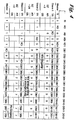
- FIG. 4 shows the tabular representation of the configuration cycle 1, based on the arrangement in FIG. 1.
- FIG. 5 shows the tabular representation of the configuration cycle 2, based on the arrangement in FIG. 1.
- the ring consists of a master and 3 subsystems slave 1 - slave 3.
- Each subsystem consists essentially of an optoelectric receiving device E and an electro optical transmission device S, from a telegram register TR, a working register AR, a data memory DS and a device BZ for setting the relative address.
- the subsystems without their own intelligence are limited to a fixed data length of a maximum of 4 bytes.
- the relative address BZ of the slave 1 subsystem is three bytes (16-24V outputs) and that of the subsystem 3 is two bytes (8-24V inputs).
- the slave 2 subsystem has its own intelligence and has a variable data length. In this case 24 bytes (16 analog inputs and 4 analog outputs).
- the participants, masters and subsystems slave 1 - slave 3 are arranged in a ring topology by means of optical fibers.
- the configuration, i.e. the ring participants are recorded and identified by the central control system master after initialization and ring synchronization.
- FIG. 2 shows the telegram of configuration cycle 1 that is used according to the invention in the exemplary arrangement according to FIG. 1.
- all subsystems slave 1 - slave 2 are in the "Wait” state and wait for instructions from the master. These instructions are sent in the configuration cycle and in the data cycle.
- the configuration cycle KZ1 starts from the "Listen Delimiter” state and the master sends "Idle signal" (log.1) at least 8 bit times.
- the slave 1 subsystem recognizes the start byte KD after idle signal 15, it begins with its configuration. If the entire ring is synchronized, all participants, master and slave 1-3 are in the "Listen Delimiter" state (waiting). The master sends the start byte KD, the address byte AB with the value "0", the frame check sum via the address byte AB corresponding to the address byte “repeat” ABr again "0", then the start byte KD1, followed by, during that Configuration cycle KZ1 definable 256 bytes.
- the first ring subscriber slave 1 is a subscriber with a fixed number of bytes BZ and is set to 3 bytes in terms of hardware.
- the address "0" received from the master stores slave 1, via its transfer register TR, in its working register AR, adds up its 3 bytes and transfers them to the address byte AB of the configuration tele by means of the transfer register TR grammes KT1 and sends the address 3 to the next subsystem slave 2.
- slave 1 forms the frame checksum of the address 3 and sends it via the transfer register TR to the subsystem slave 2 as address byte "repeat" ABr.
- slave 1 receives the next start byte KD1 and knows that the first three data bytes it receives are intended for it.
- Slave 1 reads the watchdog time in the first byte and overwrites the data byte DB1 with its identification identified in the data memory. In this case a 3 byte device with 8 ⁇ 24 V inputs. The data bytes DB2 and DB3 remain unused. All subsequent data bytes are only passed on when the frame checksum is created.
- the subsystem slave 2 has received the address "3" from slave 1 and writes this address in its working register AR.
- Slave 2 is an intelligent subsystem with variable data length, which can be assigned by the subsystem Slave 2 itself or by the master. This allows the ring to dynamically adapt optimally to its time-changing problem. 4 data bytes are permanently preselected for slave 2.
- the configuration cycle KZ1 ends with the last data byte DB256 received from the master and finally the frame check sum. At this point, all sub-systems slave 1-slave 3 are detected and identified.
- the master has created an image of the ring system. He knows the position and number of participants, their relative address and their identification.
- the slave 2 subsystem was determined by him as an intelligent subscriber, which has a variable data length and, for absolute addressing of all subscribers on the ring, forces a second configuration cycle KZ2.
- the configuration is complete when the data byte DB256 reaches the recipient of the master.
- the system is then again in the "Listen Delimiter" state.
- the master sends an idle signal (log. 1) and waits for n data cycles.
- the first data byte becomes the configuration byte.
- the configuration byte sent by the master can contain e.g. the setting and the watchdog timer and can be written into the data memory DS of the subsystems.
- the subsystem overwrites this configuration byte with its identity.
Landscapes
- Engineering & Computer Science (AREA)
- Computer Networks & Wireless Communication (AREA)
- Signal Processing (AREA)
- Small-Scale Networks (AREA)
Description
Die Erfindung betrifft ein Verfahren zur Erfassung und Identifizierung von Busteilnehmern in einem 1-Master- n-Slave-System, wobei sich die vernetzten Teilnehmer in einem ringtopologisch angeordneten Bussystem befinden und mittels einem als übertragungsmedium ausgeführten Lichtwellenleiter Informationen mit geringen Datenmengen bis in die niedrigste Feldebene austauschen. Ein solches Verfahren ist in ELEKTROTECHNISCHE ZEITSCHRIFT - ETZ. vol. 108, no. 2, Januar 87, BERLIN DE Seiten 52 - 57; B. KÖNIG et al.: "Glasfasertechnik für die Zugsteuerung" veröffentlicht.The invention relates to a method for detecting and identifying bus subscribers in a 1-master-n-slave system, the networked subscribers being located in a ring-topologically arranged bus system and by means of an optical waveguide designed as a transmission medium, information with small amounts of data down to the lowest field level change. Such a procedure is in ELEKTROTECHNISCHE MAGAZINE - ETZ. vol. 108, no. 2, January 87, BERLIN DE pages 52 - 57; B. KÖNIG et al .: "Fiber optic technology for train control" published.
Bei den bekannten bitseriellen Übertragungsverfahren erfolgt die Identifizierung und Erfassung der Teilnehmer zyklisch und ist in jedem Übertragungstelegramm protokolliert. Die Effeziens der Nutzdatenübertragung leidet unter der ständigen Mitführung der Verwaltungsdaten, wie Kontrollstrukturen z.B Token-Verwaltung, Sicherheitszyklen und Frage- und Antwortzyklen. Gerade im Bereich der untersten Feldebene wird das Verhältnis der Nutzdaten zu den Verwaltungsdaten immer schlechter, da es sich in der Eingangs- Ausgangsebe meißt um einfachste Feld-Ein/Ausgabegeräte (Schalter, Tasten, Lampen, Schütze) und somit um Ein-Bit-Informationen handelt.In the known bit-serial transmission methods, the participants are identified and recorded cyclically and are logged in each transmission telegram. The efficiency of the user data transmission suffers from the constant carrying of the administrative data, such as control structures e.g. token management, security cycles and question and answer cycles. Especially in the area of the lowest field level, the ratio of the user data to the administrative data is getting worse, since it is measured in the input-output level by the simplest field input / output devices (switches, buttons, lamps, contactors) and thus by one-bit information acts.
Die Erfindung stellt sich zur Aufgabe, ein Verfahren zur Erfassung und Identifizierung der Busteilnehmer in einem Ringsystem anzugeben, bei dem das übliche Overhead während der Übertragung der Nutzdaten auf ein Minimum begrenzt wird und die Erfassung und Identifizierung der Teilnehmer in einem Konfigurationszyklus erfolgt.The invention has for its object a method for detecting and identifying the bus participants in one Specify ring system in which the usual overhead during the transmission of the user data is limited to a minimum and the acquisition and identification of the participants takes place in a configuration cycle.
Diese Aufgabe wird erfindungsgemäß dadurch gelöst, daß das zentrale Steuersystem nach jeder Neuinitialisierung eine zyklische Konfiguration des Ringsystems einleitet, wobei jeder im Ringsystem eingebundene Teilnehmer derart erfaßt wird, daß in einem ersten Konfigurationszyklus die Teilnehmererkennung und Teilnehmeridentifizierung durch eine geographische Adressierung erfolgt, indem ein Konfigurationstelegramm, welches im wesentlichen aus einem Startbyte, einem Adressbyte mit der Wertigkeit 0 ond einer Folge von Datenbytes besteht, zum ersten Ringteilnehmer gesendet wird und daß dieser Teilnehmer das emfangene Adressbyte in seinem Adressregister als absolute Adresse ablegt und durch hinzuaddieren seiner hardwaremäßig eingestellten relativen Adresse das Adressbyte des Konfigurationstelegramms für den nächsten Teilnehmer neu generiert, welches dann mit dem, um die Adressbytezahl des Teilnehmers erhöhten Adressbyte zum Teilnehmer gesendet wird und daß der Teilnehmer und jeder weitere Teilnehmer diese Prozedur durchläuft und daß am Ende des Ringes dem zentralen Steuerungssystem ein genaues Abbild über die Anzahl der Teilnehmer, deren zugeordneter relativen Adresse aus der Summierung aller Adressbytezahlen im Adreßbyte und deren zugeordnete, errechnete und absolute Adresse aus den entsprechenden Arbeitsregistern, deren Werte in die Datenbytefolge des Konfigurationstelegramms, während des Konfigurationszyklusses, eingeschrieben wurden, zur Verfügung steht, wobei für einen intelligenten Teilnehmer mit variabler Datenlänge vier Datenbytes im Konfigurationstelegramm reserviert wird und daß sich das zentrale Steuerungssystem aus dem Konfigurationstelegramm eine Abbildliste erstellt.This object is achieved according to the invention in that the central control system initiates a cyclic configuration of the ring system after each reinitialization, each subscriber integrated in the ring system being recorded in such a way that in a first configuration cycle the subscriber recognition and subscriber identification takes place by means of a geographical addressing, by means of a configuration telegram, which essentially consists of a start byte, an address byte with the
In den abhängigen Ansprüchen 2 bis 4 sind vorteilhafte Weiterbildungen in Verbindung mit dem Hauptanspruch gekennzeichnet. Das vorgestellte erfindungsgemäße Verfahren bezieht sich auf ein 1-Master- n-Slavesystem. Die Mastersteuerung verwaltet das Protokoll der Konfigurationszyklen und besitzt am Ende der Konfigurationszyklen eine genaue Orientierung über die Anordnung der Teilnehmer im Ringsystem und errechnet aus der Kenntnis der relativen Adresse jedes Teilnehmeres deren absolute Adresse und schreibt diese in das Adressregister der Teilnehmer ein. Sind die zwei Konfigurationszyklen abgeschlossen, können n-Datenzyklen folgen, wobei nur die bei der Identifikation der Teilnehmer eermittelten Datenbytes den Datenzyklus belasten. Alle möglichen folgenden Datenbytes werden vom Kommunikationsprozokoll ignoriert und abgeschnitten. Problemlos können in Ringsystemen, die das erfindungsgemäße Verfahren nutzen, nach Auschaltung der Steuerspannung, Teilnehmer in den Ring eingefügt oder entfernt werden. Nach Einschalten der Steuerspannung erfolgt die Neuinitiallisierung des Ringsystems mit den beschriebenen Konfigurationszyklen. Nachfolgend sei das erfindungsgemäße Verfahren mittels der Figuren der beiliegenden Zeichnung mit einer beispielhaften Anordnung von Teilnehmern näher erläutert.In the
Es zeigen :Show it :
Fig. 1 eine einfache und beispielhafte Anordnung eines 1-Master - n-Slave-Ringsystems, bei dem das Verfahren Anwendung findet.Fig. 1 shows a simple and exemplary arrangement of a 1-master - n-slave ring system, in which the method is used.
Fig. 2 das Telegramm für den Konfigurationszyklus 1, daß bei der beispielhaften Anordnung nach Fig. 1 Anwendung findet.Fig. 2 shows the telegram for the
Fig. 3 das Telegramm für den Konfigurationszyklus 2, daß bei der beispielhaften Anordnung nach Fig. 1 Anwendung findet.Fig. 3 shows the telegram for the
Fig. 4 die tabellarische Darstellung des Konfigurationszyklus 1, bezogen auf die Anordnung in Fig. 1.4 shows the tabular representation of the
Fig. 5 die tabellarische Darstellung des Konfigurattionszyklus 2, bezogen auf die Anordnung in Fig. 1.5 shows the tabular representation of the
Die Fig. 1 zeigt eine einfache und beispielhafte Anordnung eines 1-Master - n-Slave-Ringsystems, bei dem das erfindungsgemäße Verfahren Anwendung findet. Hierbei besteht der Ring aus einem Master und 3 Untersystemen Slave 1 - Slave 3. Jedes Untersystem besteht im wesentlichen aus einer optoelektrischen Emfangseinrichtung E und einer elektro optischen Sendeeinrichtung S, aus einem Telegrammregister TR, einem Arbeitsregister AR, einem Datenspeicher DS und einer Einrichtung BZ zur Einstellung der relativen Adresse. Die Untersysteme ohne eigene Intelligenz sind auf eine feste Datenlänge von maximal 4 Byte begrenzt. In dieser beispielhaften Anordnung Fig.1 beträgt die relative Adresse BZ des Untersystems Slave 1 drei Byte (16- 24V-Ausgänge) und die des Untersystems 3 zwei Byte (8-24V-Eingänge). Das Untersystem Slave 2 besitzt eine eigene Intelligenz und hat eine variable Datenlänge. In diesem Fall 24 Byte (16 analoge Eingänge und 4 analoge Ausgänge).1 shows a simple and exemplary arrangement of a 1-master-n-slave ring system in which the method according to the invention is used. The ring consists of a master and 3 subsystems slave 1 -
Die Teilnehmer, Master und Untersysteme Slave 1 - Slave 3 sind mittels Lichtwellenleiter ringtopologisch angeordnet. Die Konfiguration, d.h. die Erfassung und Identifizierung der Ringteilnehmer erfolgt nach der Initialisierung und Ringsynchronisierung durch das zentrale Steuersystem Master.The participants, masters and subsystems slave 1 -
Fig. 2 zeigt das Telegramm des Konfigurationszyklus 1, daß erfindungsgemäß bei der beispielhaften Anordnung nach Fig. 1 Anwendung findet. Nach der Ringsynchronisation befinden sich alle Untersysteme Slave 1 - Slave 2 im Zustand "Warten" und warten auf Anweisung vom Master. Diese Anweisungen werden im Konfigurationszyklus und im Datenzyklus gesendet. Der Konfigurationszyklus KZ1 startet ausgehend vom Zustand "Listen Delimiter"und der Master sendet "Idle-Signal" (log.1) mindestens 8 Bitzeiten.FIG. 2 shows the telegram of
Es folgt der "Konfigurationsdelimiter" als Startbyte KD und daran anschließend das Adressbyte AB und das Adressbyte "repeat" ABr. Jeder Teilnehmer Slave 1 - Slave 3 vergleicht die Adressbytes AB und ABr auf Übereinstimmung. Bei Nichtübereinstimmung wird wieder der Zustand "Listen Delimiter" eingenommen. Einem weiteren "Konfigurations Delimiter" als Startbyte KD1 folgen die Datenbytes DB1-DB256.This is followed by the "configuration delimiter" as the start byte KD and then the address byte AB and the address byte "repeat" ABr. Each slave 1 -
Anhand der Fig. 4, die eine tabellarische Darstellung des Konfigurationszyklus 1 darstellt, soll dieser näher beschrieben werden. Erkennt das Untersystem Slave 1 nach Idle-Signal 15 das Startbyte KD, beginnt es mit seiner Konfiguration. Ist der gesamte Ring synchronisiert, so befinden sich alle Teilnehmer, Master und Slave 1-3 im Zustand "Listen Delimiter " (Warten). Der Master sendet das Startbyte KD, das Adressbyte AB mit der Wertigkeit "0", die Frame-Check-Summe über das Adressbyte AB entsprechend dem Adressbyte "repeat" ABr also nocheinmal "0", dann das Startbyte KD1, gefolgt von, während dem Konfigurationszyklus KZ1 definierbaren 256 Byte. Der erste Ringteilnehmer Slave 1 ist ein Teilnehmer mit fester Bytezahl BZ und ist hardwaremäßig fest auf 3 Byte eingestellt. Die vom Master emfangene Adresse "0" speichert Slave 1, über sein Transferregister TR, in seinem Arbeitsregister AR ab, addiert seine 3 Byte auf, trägt sie mittels des Transferregisters TR in das Adressbyte AB des Konfigurationstele gramms KT1 ein und sendet die Adresse 3 dem nächsten Untersystem Slave 2. Dann bildet Slave 1 die Frame-CheckSumme von der Adresse 3 und sendet sie Über das Transferregister TR dem Untersystem Slave 2 als Adressbyte "repeat" ABr. Dann emfängt Slave 1 das nächste Startbyte KD1 und weiß, daß die ersten drei Datenbytes, die er emfängt, für ihn bestimmt sind. Slave 1 ließt im ersten Byte die Watchdog-Time und überschreibt das Datenbyte DB1 mit seiner im Datenspeicher gekennzeichneten Identifikation. In diesem Fall einen 3 Byte Teilnehmer mit 8 × 24 V-Eingängen. Die Datenbytes DB2 und DB3 bleiben ungenutzt. Alle folgenden Datenbytes werden mit Bildung der Frame-CheckSumme nur noch durchgereicht. Das Untersystem Slave 2 hat die Adresse "3" von Slave 1 erhalten und schreibt diese Adresse in sein Arbeitsregister AR. Slave 2 ist ein intelligentes Untersystem mit variabler Datenlänge, die vom Untersystem Slave 2 selbst, oder vom Master zugewiesen werden kann. Damit kann der Ring sich dynamisch optimal an seine zeitlich veränderliche Problemstellung anpassen. Für Slave 2 werden 4 Datenbyte fest vorgewählt. Die Addition des Adressbytes mit der vorgewählten Bytezahl 4 ergibt die Adresse "7", die zum Slave 3 gesendet wird. Die Identität von Slave 2 (24 analoge Eingänge, 4 analoge Ausgänge) und seine relative Adresse (24 Byte) werden in das das Datenbyte DB4 eingeschrieben. Slave 3 schreibt die vom Slave 2 gesendete Adresse "7" in sein Arbeitsregister AR, addiert seine relative Adresse mit der Bytezahl BZ 2 auf. Slave 3 schreibt seine Identifikation in das Datenbytebyte DB8 ein, und sendet dem Master die Adresse "9".4, which represents a tabular representation of the
Der Konfigurationszyklus KZ1 endet mit dem vom Master emfangenen letzten Datenbyte DB256 und als Abschluß die Frame-Check-Summe. Zu diesem Zeitpunkt sind alle Untersys teme Slave 1-Slave 3 erfaßt und identifiziert. Der Master hat sich ein Abbild vom Ringsystem geschaffen. Er kennt die Position und die Anzahl der Teilnehmer, deren relative Adresse sowie deren Identifikation. Das Untersystem Slave 2 wurde von ihm als intelligenten Teilnehmer ermittelt, der eine variable Datenlänge aufweist und zur absoluten Adressierung aller Teilnehmer am Ring einen zweiten Konfigurationszyklus KZ2 erzwingt.The configuration cycle KZ1 ends with the last data byte DB256 received from the master and finally the frame check sum. At this point, all sub-systems slave 1-
Fig. 3 zeigt das Telegramm des Konfigurationszyklus KZ2. Diese Zweite Konfigurationszyklus wird wegen der Existenz des intelligenten Teilnehmers Slave 2 und dessen variable Datenlänge notwendig. In diesem Zyklus wird jedem Teilnehmer die absolute Adressierung in das Arbeitsregister geschrieben.3 shows the telegram of the configuration cycle KZ2. This second configuration cycle is necessary because of the existence of the
Fig. 5 zeigt eine tabellarische Darstellung des Konfigurationszyklus KZ2, bezogen auf die Anordnung in Fig. 1. Nach dem "Konfigurations Delimiter" als Startbyte KD2 sendte der Master die Datenbytes in aufsteigender Reihenfolge. Im Datenbyte DB1 steht die absolute Adresse "0" für Slave 1. Sie wird nochmals in das Arbeitsregister geschrieben. Für Slave 2 steht im Datenbyte DB2 die Absolute Adresse "3". Im Datenbyte 3 des nächsten und letzten Ringteilnehmers, Slave 3, steht die Summe aus relativer Adresse "24" und der absoluten Adresse "3" des Teilnehmers Slave 2. Die absolute Adresse "27" wird dem Teilnehmer Slave 3 in das Arbeitsregister AR eingeschrieben.5 shows a tabular representation of the configuration cycle KZ2, based on the arrangement in FIG. 1. After the "configuration delimiter" as the start byte KD2, the master sent the data bytes in ascending order. The absolute address "0" stands for
Die Konfiguration ist abgeschlossen, wenn das Datenbyte DB256 den Emfänger des Masters erreicht. Das System befindet sich danach wieder im Zustand "Listen Delimiter". Der Master sendet Idle-Signal (log. 1) und wartet auf n-Datenzyklen.The configuration is complete when the data byte DB256 reaches the recipient of the master. The system is then again in the "Listen Delimiter" state. The master sends an idle signal (log. 1) and waits for n data cycles.
Im Konfigurationszyklus wird das erste Datenbyte jeweils zum Konfigurationsbyte. Dabei kann das vom Master gesendete Konfigurationsbyte z.B die Einstellund des Watchdog-Timers beinhalten und in den Datenspeicher DS der Untersysteme eingeschrieben werden. Im gleichen Zyklus überschreibt das Untersystem dieses Konfigurationsbyte mit seiner Identität.In the configuration cycle, the first data byte becomes the configuration byte. The configuration byte sent by the master can contain e.g. the setting and the watchdog timer and can be written into the data memory DS of the subsystems. In the same cycle, the subsystem overwrites this configuration byte with its identity.
Claims (4)
- Procedure allowing the registration and identification of bus participants in a one-master-n-slave system, the network participants being situated within a bus system with a ring topological arrangement and exchanging information comprising small amounts of data by means of an optical waveguide arranged as a medium of transmission up to the lowest level of communication, in which the central control system (master) starts a cyclic configuration of the ring system after every reinitialization during which every participant involved in the ring system (slave 1 through slave n) is registered and identified in such a way that participant recognition and participant identification is done by geographic addressing in a first configuration cycle (KZ1), during which a configuration telegram (KT 1) which essentially consists of a start byte (KD), an address byte (AB) with a valence of 0, another address byte (ABr) with a valence of 0, and a series of data bytes (DB0 through DBn) is sent to the first ring participant (slave 1) and in which this participant (slave 1) files the received address byte (AB) as an absolute address in its address register (AR) and regenerates the address byte (AB) of the configuration telegram (KT1) for the next participant (slave 2) by adding its relative address (BZ) set on the hardware level, this configuration telegram (KT1) then includes the address byte (AB) increased by the address byte number (BZ) of the participant (slave 1) and it is sent to the participant (slave 2) and in which the participant (slave 2) and every other participant (slave 3 through slave n) follows this procedure and in which the central control system (master) at the end of the ring has a precise picture of the number of participants (slave 1 through slave n), of the relative address assigned to them resulting from the adding-up of all address byte numbers (BZ) in the address byte (AB) and of the absolute address assigned to them and arrived at by calculation obtained from the corresponding working registers (AR), the values n of which have been written into the data byte sequence.(DBO through DBn) of the configuration telegram (KT1) during the configuration cycle (KZ1), while four data bytes (DB5-DB8) are reserved for an intelligent participant (slave 3) with a variable data length in the configuration telegram (KT1) and in which the central control system (master) prepares itself a map list (ABL) on the basis of the configuration telegram (KT1).
- Procedure allowing the configuration of control systems as claimed in claim 1, wherein every participant (slave 1 through slave n) enters its identification into the data byte sequence (DB0 through DBn) of the configuration telegram (KT1) according to its address (AB) during configuration.
- Procedure allowing the configuration of control systems as claimed in claims 1 and 2, wherein the central control system recognizes a participant (slave 3) with a variable data length in its map list prepared during the first configuration cycle (KZ1) and is forced into a second configuration cycle (KZ2) during which a configuration telegram (KT2) consisting of a start byte (KD2) and of the subsequent data bytes (DB0 through DBn) is sent into the ring, while the data bytes (DB) following after the start byte (KD2) are reserved in an ascending order according to the number of participants (slave 1 through slave n) and their corresponding byte numbers (BZ) and are used by every participant to write its absolute address (AB) into its address register (AR) once again.
- Procedure allowing the configuration of control systems as claimed in claims 1 through 3, wherein any number of data cycles follows on the configuration cycles (KZ1, KZ2) and wherein a new configuration is only done after the cutting and resetting of the control voltage.
Priority Applications (1)
| Application Number | Priority Date | Filing Date | Title |
|---|---|---|---|
| DE58908241T DE58908241D1 (en) | 1989-11-17 | 1989-11-17 | Procedure for the identification of bus users. |
Applications Claiming Priority (1)
| Application Number | Priority Date | Filing Date | Title |
|---|---|---|---|
| DE19883838152 DE3838152A1 (en) | 1988-11-10 | 1988-11-10 | METHOD AND IDENTIFICATION OF BUS PARTICIPANTS |
Publications (2)
| Publication Number | Publication Date |
|---|---|
| EP0428810A1 EP0428810A1 (en) | 1991-05-29 |
| EP0428810B1 true EP0428810B1 (en) | 1994-08-24 |
Family
ID=6366897
Family Applications (1)
| Application Number | Title | Priority Date | Filing Date |
|---|---|---|---|
| EP19890710079 Expired - Lifetime EP0428810B1 (en) | 1988-11-10 | 1989-11-17 | Method for identifying bus ticket-holders |
Country Status (2)
| Country | Link |
|---|---|
| EP (1) | EP0428810B1 (en) |
| DE (1) | DE3838152A1 (en) |
Cited By (1)
| Publication number | Priority date | Publication date | Assignee | Title |
|---|---|---|---|---|
| US11442736B2 (en) * | 2017-05-24 | 2022-09-13 | Wago Verwaltungsgesellschaft Mbh | Determination of data bus subscribers of a local bus |
Families Citing this family (10)
| Publication number | Priority date | Publication date | Assignee | Title |
|---|---|---|---|---|
| DE4020143A1 (en) * | 1990-06-25 | 1992-02-20 | Messer Griesheim Gmbh | Arc welding current source - connected in series with ancillary equipment and microprocessor |
| DE4124733C2 (en) * | 1991-07-25 | 1994-06-09 | Peters & Zabransky Ingenieurge | Data transmission system |
| EP0682431B1 (en) * | 1994-05-09 | 2002-10-02 | Europlex Research Limited | A ring network system |
| DE4431206A1 (en) * | 1994-09-02 | 1996-03-07 | Sel Alcatel Ag | Connection identification for use in multiprocessor system |
| DE29908319U1 (en) * | 1999-05-10 | 2000-08-31 | Siemens Ag | Network with several participants as well as participants for such a network |
| DE19934514C5 (en) | 1999-07-22 | 2013-03-14 | Pilz Gmbh & Co. Kg | Method for configuring a bus device connected to a fieldbus |
| DE102004037227A1 (en) * | 2004-07-30 | 2006-02-16 | Sick Maihak Gmbh | Method and device for addressing subscribers of a bus system |
| DE102004041092A1 (en) * | 2004-08-24 | 2006-03-09 | Bosch Rexroth Aktiengesellschaft | A method for assigning a device address to a substation in a network and a substation and a main station for a network |
| DE102006013578B4 (en) | 2006-03-22 | 2008-03-27 | Phoenix Contact Gmbh & Co. Kg | Method and control and data transmission system for checking the installation location of a secure communication subscriber |
| US8819162B2 (en) | 2012-05-07 | 2014-08-26 | Tesla Motors, Inc. | Host communications architecture |
Family Cites Families (4)
| Publication number | Priority date | Publication date | Assignee | Title |
|---|---|---|---|---|
| ATE34263T1 (en) * | 1983-05-31 | 1988-05-15 | Oesterr Forsch Seibersdorf | METHOD AND ARRANGEMENT FOR TRANSMITTING INFORMATION IN A DATA RING. |
| JPH0657008B2 (en) * | 1985-04-24 | 1994-07-27 | 株式会社日立製作所 | System structure recognition method for multiloop transmission system |
| EP0290934B1 (en) * | 1987-05-14 | 1994-01-19 | Siemens Aktiengesellschaft | Method of setting up an address table in a ring communication network |
| DE3806493A1 (en) * | 1988-03-01 | 1989-09-14 | Kloeckner Moeller Elektrizit | Bus system |
-
1988
- 1988-11-10 DE DE19883838152 patent/DE3838152A1/en active Granted
-
1989
- 1989-11-17 EP EP19890710079 patent/EP0428810B1/en not_active Expired - Lifetime
Cited By (1)
| Publication number | Priority date | Publication date | Assignee | Title |
|---|---|---|---|---|
| US11442736B2 (en) * | 2017-05-24 | 2022-09-13 | Wago Verwaltungsgesellschaft Mbh | Determination of data bus subscribers of a local bus |
Also Published As
| Publication number | Publication date |
|---|---|
| DE3838152C2 (en) | 1990-10-31 |
| DE3838152A1 (en) | 1990-05-31 |
| EP0428810A1 (en) | 1991-05-29 |
Similar Documents
| Publication | Publication Date | Title |
|---|---|---|
| DE3924452C2 (en) | Method for determining the address and the number of node stations in a local network | |
| EP0428810B1 (en) | Method for identifying bus ticket-holders | |
| EP2090031B1 (en) | Method and arrangement for communication on an lin bus | |
| EP0833425A2 (en) | Communication system for a power supply network | |
| DE3736081A1 (en) | Method and device for setting the addresses of subscribers connected to a bus | |
| EP0616286A1 (en) | Method of allocating bus addresses | |
| DE2750175A1 (en) | ANALOG-PULSE-WIDTH-DIGITAL CONVERSION DATA TRANSMISSION SYSTEM | |
| DE19721740B4 (en) | Control method for media access on a serial bus | |
| EP1189382A2 (en) | Method for determining and visualizing network topologies | |
| EP1537721A1 (en) | Bus | |
| EP0725516B1 (en) | Method for determining the position of a participant in a network | |
| DE4029290C2 (en) | ||
| DE102015107865A1 (en) | Bus system and method for allocating addresses of bus users of a bus system | |
| DE1275088B (en) | Circuit arrangement for computer-controlled storage switching systems | |
| DE102020200931A1 (en) | CONTROL SYSTEM WITH SEVERAL FUNCTION MODULES AND ADDRESSING PROCEDURES FOR ITS FUNCTION MODULES | |
| WO2000004428A1 (en) | Method and system for configuring a computer-aided system | |
| DE4129412A1 (en) | METHOD FOR DATA TRANSFER AND DATA PROCESSING SYSTEM WITH DISTRIBUTED COMPUTER NODES | |
| EP1642207B1 (en) | Allocation of station addresses to communication users in a bus system | |
| DE10037969C2 (en) | Process for the detection of flexible networking of modules with any network topology and for the exchange of information between such modules | |
| DE4433116B4 (en) | Method for selectively calling network elements | |
| DE3346806A1 (en) | Method and circuit arrangement for transmitting data signals | |
| EP0500987B1 (en) | Method for detecting terminal addresses in a bridge connecting local area networks | |
| DE3402577A1 (en) | Bus arrangement for transmitting data between a multiplicity of subscribers | |
| EP0894381A1 (en) | Process for controlling access to a transmission channel used in common by several data sources | |
| DE10310622B4 (en) | Method and data transmission system for bidirectional, synchronous data transmission |
Legal Events
| Date | Code | Title | Description |
|---|---|---|---|
| PUAI | Public reference made under article 153(3) epc to a published international application that has entered the european phase |
Free format text: ORIGINAL CODE: 0009012 |
|
| AK | Designated contracting states |
Kind code of ref document: A1 Designated state(s): BE CH DE ES FR GB IT LI LU |
|
| RAP1 | Party data changed (applicant data changed or rights of an application transferred) |
Owner name: KLOECKNER-MOELLER GMBH |
|
| 17P | Request for examination filed |
Effective date: 19911031 |
|
| 17Q | First examination report despatched |
Effective date: 19940121 |
|
| GRAA | (expected) grant |
Free format text: ORIGINAL CODE: 0009210 |
|
| AK | Designated contracting states |
Kind code of ref document: B1 Designated state(s): BE CH DE ES FR GB IT LI LU |
|
| PG25 | Lapsed in a contracting state [announced via postgrant information from national office to epo] |
Ref country code: IT Free format text: LAPSE BECAUSE OF FAILURE TO SUBMIT A TRANSLATION OF THE DESCRIPTION OR TO PAY THE FEE WITHIN THE PRESCRIBED TIME-LIMIT;WARNING: LAPSES OF ITALIAN PATENTS WITH EFFECTIVE DATE BEFORE 2007 MAY HAVE OCCURRED AT ANY TIME BEFORE 2007. THE CORRECT EFFECTIVE DATE MAY BE DIFFERENT FROM THE ONE RECORDED. Effective date: 19940824 Ref country code: BE Effective date: 19940824 Ref country code: GB Effective date: 19940824 Ref country code: FR Effective date: 19940824 Ref country code: ES Free format text: THE PATENT HAS BEEN ANNULLED BY A DECISION OF A NATIONAL AUTHORITY Effective date: 19940824 |
|
| REF | Corresponds to: |
Ref document number: 58908241 Country of ref document: DE Date of ref document: 19940929 |
|
| PG25 | Lapsed in a contracting state [announced via postgrant information from national office to epo] |
Ref country code: CH Effective date: 19941130 Ref country code: LI Effective date: 19941130 Ref country code: LU Free format text: LAPSE BECAUSE OF NON-PAYMENT OF DUE FEES Effective date: 19941130 |
|
| EN | Fr: translation not filed | ||
| GBV | Gb: ep patent (uk) treated as always having been void in accordance with gb section 77(7)/1977 [no translation filed] |
Effective date: 19940824 |
|
| PGFP | Annual fee paid to national office [announced via postgrant information from national office to epo] |
Ref country code: DE Payment date: 19950317 Year of fee payment: 6 |
|
| PLBE | No opposition filed within time limit |
Free format text: ORIGINAL CODE: 0009261 |
|
| STAA | Information on the status of an ep patent application or granted ep patent |
Free format text: STATUS: NO OPPOSITION FILED WITHIN TIME LIMIT |
|
| REG | Reference to a national code |
Ref country code: CH Ref legal event code: PL |
|
| 26N | No opposition filed | ||
| PG25 | Lapsed in a contracting state [announced via postgrant information from national office to epo] |
Ref country code: DE Effective date: 19960801 |