EP0427201B1 - Satellite beam-forming network system having improved beam shaping - Google Patents
Satellite beam-forming network system having improved beam shaping Download PDFInfo
- Publication number
- EP0427201B1 EP0427201B1 EP19900121219 EP90121219A EP0427201B1 EP 0427201 B1 EP0427201 B1 EP 0427201B1 EP 19900121219 EP19900121219 EP 19900121219 EP 90121219 A EP90121219 A EP 90121219A EP 0427201 B1 EP0427201 B1 EP 0427201B1
- Authority
- EP
- European Patent Office
- Prior art keywords
- signals
- additional
- beams
- target area
- antenna
- Prior art date
- Legal status (The legal status is an assumption and is not a legal conclusion. Google has not performed a legal analysis and makes no representation as to the accuracy of the status listed.)
- Expired - Lifetime
Links
Images


Classifications
-
- H—ELECTRICITY
- H01—ELECTRIC ELEMENTS
- H01Q—ANTENNAS, i.e. RADIO AERIALS
- H01Q3/00—Arrangements for changing or varying the orientation or the shape of the directional pattern of the waves radiated from an antenna or antenna system
- H01Q3/26—Arrangements for changing or varying the orientation or the shape of the directional pattern of the waves radiated from an antenna or antenna system varying the relative phase or relative amplitude of energisation between two or more active radiating elements; varying the distribution of energy across a radiating aperture
- H01Q3/30—Arrangements for changing or varying the orientation or the shape of the directional pattern of the waves radiated from an antenna or antenna system varying the relative phase or relative amplitude of energisation between two or more active radiating elements; varying the distribution of energy across a radiating aperture varying the relative phase between the radiating elements of an array
- H01Q3/34—Arrangements for changing or varying the orientation or the shape of the directional pattern of the waves radiated from an antenna or antenna system varying the relative phase or relative amplitude of energisation between two or more active radiating elements; varying the distribution of energy across a radiating aperture varying the relative phase between the radiating elements of an array by electrical means
- H01Q3/40—Arrangements for changing or varying the orientation or the shape of the directional pattern of the waves radiated from an antenna or antenna system varying the relative phase or relative amplitude of energisation between two or more active radiating elements; varying the distribution of energy across a radiating aperture varying the relative phase between the radiating elements of an array by electrical means with phasing matrix
-
- H—ELECTRICITY
- H01—ELECTRIC ELEMENTS
- H01Q—ANTENNAS, i.e. RADIO AERIALS
- H01Q25/00—Antennas or antenna systems providing at least two radiating patterns
- H01Q25/007—Antennas or antenna systems providing at least two radiating patterns using two or more primary active elements in the focal region of a focusing device
-
- H—ELECTRICITY
- H01—ELECTRIC ELEMENTS
- H01Q—ANTENNAS, i.e. RADIO AERIALS
- H01Q3/00—Arrangements for changing or varying the orientation or the shape of the directional pattern of the waves radiated from an antenna or antenna system
- H01Q3/26—Arrangements for changing or varying the orientation or the shape of the directional pattern of the waves radiated from an antenna or antenna system varying the relative phase or relative amplitude of energisation between two or more active radiating elements; varying the distribution of energy across a radiating aperture
- H01Q3/2605—Array of radiating elements provided with a feedback control over the element weights, e.g. adaptive arrays
- H01Q3/2611—Means for null steering; Adaptive interference nulling
- H01Q3/2629—Combination of a main antenna unit with an auxiliary antenna unit
Landscapes
- Aerials With Secondary Devices (AREA)
- Variable-Direction Aerials And Aerial Arrays (AREA)
Description
- This application relates to US 4 882 588 and WO 88/04837.
- This invention relates to an antenna system and a method of operating same in accordance with the generic clauses of
claims 1 and 14, especially for satellites to communicate with ground stations and, more particularly, to an antenna system for satellites incorporating an antenna array for producing a communicating beam which has improved side lobe characteristics around the fringes of the ground area covered by the antenna. - Satellites are now employed for providing communication, such as land mobile telephone service, between distant points on the surface of the earth. One embodiment of such a system of considerable interest is that in which the satellite travels in a geostationary orbit about the earth. The satellite may be located at a fixed position above the United States and carries an antenna having a sufficient beam width in the north-south direction and in the east-west direction to permit the reception and transmission of communication signals between any two points in the United States. The beam width in the north-south direction can be enlarged to include both United States and Canada, if desired. A beam width of approximately 4.5° in the north-south direction is sufficient to cover both Canada and the United States. The beam width in the east-west direction should be approximately 80 to provide the desired coverage. A problem arises in that the use of an antenna having the foregoing beam width in the north-south and east-west directions has less signal gain than is desired. This necessitates larger power amplifiers for driving radiating elements of the antenna.
- In previous satellite communication systems, such a wide beam width antenna has employed at least two overlapping beams to provide the coverage. The generation of such beams with a desired overlap until very recently required the use of separate large reflectors each having a diameter of about 16 feet. In the construction of communication satellites, however, it is desirable to reduce physical sizes, weights, and power requirements to facilitate the construction and launching of such satellites.
- In Application WO 87/02191, entitled "STEERED-BEAM SATELLITE COMMUNICATION SYSTEM," which is hereby incorporated by reference, there is disclosed a system for communicating via satellite between ground stations. The system comprises a set of ground stations spaced apart along an arc of the earth's surface and a satellite positioned above the earth in view of the arc. An array of radiating elements is deployed on the satellite, and a frequency responsive beam former connected to the radiating elements is provided for forming a beam of electromagnetic radiation. The beam is steerable in response to a carrier frequency of the radiation to intercept individual ones of the stations in seriatim. The frequencies of an uplink carrier and of a downlink carrier respectively associated with respective ones of the ground stations vary monotonically with position along the arc to permit automatic positioning of a beam from the satellite to a ground station upon energization of a carrier frequency assigned to the ground station.
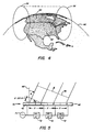
- So that the present invention may be better understood, the satellite communication system disclosed and claimed in the aforementioned application will now be discussed in some detail by reference to Figs. 1 through 5. As shown in Figs. 1 and 2, the
satellite 24 employs asimplified antenna structure 30 comprised of two conf ocal parabolic reflectors, one of which is a largemain reflector 32 and one of which is asmall subreflector 34, and a 4 x 2array 40 of eightradiating elements 42, all of which are supported by aframe 44. A front view of thearray 40 is shown in Fig. 2. Thearray 40 ofradiators 42 is rigidly secured in front of thesubreflector 34, and the subreflector is located within thesatellite 24. Themain reflector 32 is substantially larger than thesubreflector 34 and due to the larger size is folded during launch and subsequently unfurled when the satellite orspacecraft 24 has been placed in orbit. Upon being unfurled, it extends outside of thesatellite 24 as shown. Also shown in Fig. 1 within theframe 44 is other spacecraft equipment such as rocket engines and fuel tanks, thereby to demonstrate that theantenna system 30 can be easily carried by thesatellite 24. - The arrangement of the components of the
antenna system 30 provides a significant reduction in weight and complexity for a satellite antenna over that which has been employed before. This is accomplished by fabricating themain reflector 32 and thesubreflector 34 with parabolic reflecting surfaces, the two surfaces being oriented as a set of conf ocal parabolas having a common focal plane orpoint 48. Such configuration of reflecting surfaces in an antenna is described in C. Dragone and M. Cans, "Imaging Reflector Arrangements to Form a Scanning Beam Using a Small Array," Bell System Technical Journal, Vol. 58, No. 2 (Feb. 1979), pp. 501-515. The configuration provides a magnification of the effective aperture of an array of radiating elements. In the preferred configurations as shown in Figs. 1 and 2, the magnification factor is 4.7. The eightradiating elements 42 of thearray 40 represent a substantial reduction in complexity of the antenna since, if a direct radiator of similar sized elements had been employed, a total of 155 radiating elements would have been needed to give the same antenna performance. As shown in Fig. 3, a hexagonally arrangedantenna array 50 of sevenprimary radiators 52 may be used if desired in place of the 4 x 2 array of radiators mentioned above. Thearray 50 offeed elements 52 may be employed for both uplink and downlink communications. - Fig. 4 illustrates two
exemplary spot beams earth 60.Spot beam 56 extends substantially along the eastern coast of the United States 62 and Canada 64, whilespot beam 58 extends substantially along the western coast of the United States 62 and Canada 64. The satellite transmits and receives information-carrying radiation to and from ground stations located within regions of the earth's surface encompassed by the respective first andsecond spot beams respective spot beams earth 60 where the largest communications capacity is necessary to optimize antenna gain Usage by substantially limiting the amount of antenna gain which is incident upon regions wherein relatively little communications capacity is necessary, such as in sparsely populated regions. - The antenna system of
satellite 24 provide a one-dimensional beam scan (which may be considered to be a continuum of virtual spot beams) across the surface of theearth 60. Such a scan can be directed along an arc of the earth's surface, such as a longitude or a latitude, or an arc included relative to a latitude. The scanning can be accomplished most efficiently for the geography depicted in Fig. 4 by scanning in the east-west direction, providing a scan path which follows an arc of a great circle of the earth. The scanning is preferably implemented by using fixed delays (as will be described hereinafter) among radiating elements of the antenna system and by employing different frequencies for different geographical locations on the surface of the earth. Thereby, the scanning is accomplished by variation of the frequency of the radiation for each position of the beam scan (i.e., for each virtual beam), and in addition, a plurality of the beams (not shown) can be generated simultaneously by the provision of different frequencies of electromagnetic radiation in each of the beams. By use of this virtual beam technique, users at any point within the coverage of the beam scan are close to the center of one of the virtual beams. Therefore, users will typically receive 2 or 3 dB more power than they would from a comparable satellite using fixed beams. - To minimize the required electromagnetic power and provide for simplicity of antenna structure, the preferred antenna system provides beams with a generally circular cross-section and a width of 4.5° by use of the
hexagonal array 50 ofradiating elements 52 as shown in Fig. 3. Theelements 52 preferably are cup dipole feed horns one wavelength in diameter. - As an example of its use, the satellite communications system may be designated for land mobile telephone service, sometimes referred to as the Mobile Satellite (MSAT) system. Two frequency bands are assigned for such service: 866-870 MHz for the downlink band and 821-825 MHz for the uplink band. The 4 MHz width of each of these bands may be subdivided into approximately 1000 frequency slots which are individually assignable to individual ground stations on the surface of the
earth 60 for compounded single sideband voice communication. Other frequency bands may be utilized, for example, such as the L-band. If the stations were uniformly positioned from east to west, with each station being at a different longitude, approximately twelve assignable channels comprising an uplink and a downlink would be available within a scan angle of approximately 0.1 degree. - Since the channels would be uniformly spaced apart in frequency, a beam would be uniformly stepped in the east-west direction as the downlink (or uplink) frequency was shifted from one channel to the next channel. In other words, thee operating frequency of the ground station is preferably selected to match the frequency of a beam directed from the satellite to the ground station. For a uniform distribution of the stations in the east-west direction, the beam could be centered with respect to the east-west component thereof upon each of the stations. However, as a practical matter, the stations tend to be clustered in various geographic areas of the United States 62 and Canada 64 providing a nonuniform distribution of the stations along the east-west scanning path of the beam. Consequently, a peak signal amplitude cannot be obtained for all of the stations.
- By way of example, assuming that 25 ground stations are located within a scan angle of 0.1°, the corresponding reduction from peak signal amplitude is less than 0.01 dB (decibels). This represents a significant improvement over previously available satellite communication systems employing separate fixed beams wherein the average loss in signal gain relative to peak signal gain in the east-west direction was approximately 0.8 dB. As noted above, such previous satellite communication systems employed antenna systems having a plurality of large antenna reflectors, measuring approximately 16 feet in diameter, while the antenna system described in the aforementioned patent application requires only one such large reflector and a much smaller confocal subreflector as will be described hereinafter. Thus, the disclosed system provides for improved uniformity of signal gain with a simplified mechanical structure of the antenna system.
- Fig. 5 presents a diagram useful in explaining the frequency scanning operation of the antenna system. A set of four radiating
elements 42 are arranged side by side along a straight line and face anoutgoing wavefront 66 of electromagnetic radiation. The angle of incidence of the wavefront or beam scan angle is measured relative to a normal 68 to thearray 40 ofelements 42. A frequency scan is generated in a planar array antenna by introduction of a progressive time delay into the array. The progressive time delay provides for a difference in the phases of signals excited by adjacent ones of theelements 42 such that the phase difference is proportional to the frequency of the radiated signals. This explanation of the operation assumes an outgoing wavef ront, it being understood that the operation of the array ofelements 42 is reciprocal so that the explanation applies equally well to an incoming wavefront. It should be noted here that the desired frequency dependent port-to-port phase progression may be achieved by using techniques other than time delays, such as through the use of an all-pass network. The relationship of scan angle to frequency, element spacing and time delay is given by the following equations:
therefore,
wherein:
D = spacing between elements,
ϑ = beam scan angle,
λ = wavelength of radiation,
ΔΨ = phase increment between adjacent elements,
f = frequency relative to band center, and
ΔT = time delay increment between adjacent elements. - The radiating
elements 42 are energized via a source of microwave energy and a series ofdelay units 72 coupled to thesource 70. Each of thedelay units 72 provides the time delay increment referred to above in Equations (1) and (2). Thesource 70 is connected directly to anelement 42 at the left side of the array while thenext element 42 is connected by one of thedelay units 72 to thesource 70. The signals applied by thesource 70 to the third and the fourth of theelements 42 are delayed, respectively, by two and three delay increments of thedelay units 72. This provides the linear phase relationship to provide the scan angle for theoutgoing wavef ront 66. The phase increment between two adjacent ones of theradiators 42 is proportional to the product of the frequency of the radiation and the delay increment. When this product is equal to 360°, the wavef ront propagates in a direction normal to the array ofelement 42. Increasing values of frequency produce greater phase shift to direct the wavef ront to the right of the normal 68 as shown in Fig. 5, while decreasing amounts of frequency produce less phase shift and drive the wavef ront to the left of the normal. Accordingly, the wavef ront can be scanned symmetrically about the array ofelements 42. - The aforementioned application also discloses that for the case of the foregoing uplink and downlink frequency bands, and for the case of the radiating
elements 42 having a diameter of approximately one wavelength, a suitable value of differential delay, as provided by thedelay units 72 of Fig. 5, is 185 nanoseconds for the case of substantially uniform distribution of ground stations on the surface of theearth 60. To provide the east-west coverage of 8°, the uplink and the downlink beams are scanned through an arc from -4° to +4°. In view of the magnification factor of 4.7, the scan angle of thearray 40 of radiatingelements 42 must be enlarged by the same magnifying factor, 4.7, from that of the output scan from themain reflector 32. Therefore, the beam produced by the radiatingelements 42 must be scanned through an arc of 18.8° to either side of a normal to thearray 40. The foregoing value of differential delay, namely 185 nanoseconds, provides the 18.8° scan to either side of the normal to thearray 40. In the ideal situation of uniformly distributed ground stations between the east coast and the west coast of the United States and Canada, the number of channels per degree has a constant value of 1000/8 = 125. - In the situation wherein the differential delay provided by the
delay units 72 are independent of frequency, then an optimal direction of the scanned beam is obtained for the ideal situation of uniform distribution of ground stations. In the more likely situation of a nonuniform distribution of ground stations, the scanned beam may be displaced slightly from its designated ground station. As has been noted above, such a beam-pointing inaccuracy reduces the signal level by less than 0.01 decibels for a beam-pointing error of 0.1 degree. - The aforementioned patent application discloses that the scanning can be adapted to accommodate the foregoing nonuniformity in ground station distribution by introducing a frequency-responsive component to the differential delay. It gives an example of nonuniform distribution where the differential delay between columns of the
array 40 of radiating elements 42 (see Fig. 4) should vary, at least for the forming of the downlink beams, between 262 nanoseconds at the low frequency end of the transmission band to 131 nanoseconds in the high frequency end of the transmission band. Other values of delay may be employed in the beam-forming operation of uplink beams provided by the receiver of the antenna system (30). - The values of delay used in the different frequency bands, namely the uplink and downlink frequency bands, are inversely proportional to the center frequencies of these bands as is apparent from Equations (1) and (2). A reduction in the differential delay results in a reduced amount of phase shift between successive beams with a corresponding reduction in displacement of beam position on the surface of the
earth 60 from one channel to the next channel. Thereby, the beam can be more accurately positioned in a region of high density of ground stations. In a corresponding fashion, an increase in the differential delay results in increased movement of the beam as the frequency is shifted from one channel to the next channel, thus accommodating positions of the beam to a less dense distribution of ground stations. The channel number corresponds to a specific frequency in either the uplink or the downlink band. With respect to the positioning of ground stations along an arc of a great circle of theearth 60, as disclosed with reference to Fig. 4, it is seen that the frequencies selected for the various stations vary monotonically with position along the foregoing arc. - In view of the foregoing description, it is seen that the above-described communication system provides two-way communications between ground stations and a geosynchronous satellite. The assignment of specific frequencies to respective ones of the ground stations, in combination with frequency scanning of both uplink and downlink beams of the satellite (24), permits a simplification in the circuitry of the system. In addition, the use of the two confocal parabolic reflectors provides a multiplicative factor which reduces the number of elements required in the array of radiating elements. The use of a scanned beam also reduces the physical size of the antenna system by reducing the number of reflectors, resulting in a lighter weight, more efficient satellite communications system.
- It has been found that certain technical impediments exist to the commercial implementation of the above-described confocal reflector system. One such impediment is the system s lack of efficiency. Due to spacecraft size limitations, the
subreflector 34 cannot be constructed large enough (in terms of wavelengths) to perform with acceptable efficiency. These size limitations also restrict the size of the main reflector and the focal lengths that may be used in the confocal arrangement. - Another impediment is the beam distortion which is present when the beam scans toward the edge of the coverage area. This beam distortion is undesirable because it reduces the overall capacity of the system to transmit information.
- It would be desirable, in order to achieve a further weight-saving and simplification of the aforementioned satellite communications system, to eliminate the subreflector altogether while still utilizing a relatively low number of radiating elements. It would also be very advantageous to be able to combine the power of output signals from several individual amplifiers operated in parallel into an individual one or small group of the radiating elements so as to produce a stronger spot beam in any given location along the area of the earth being swept by the scanning beam. It would further be desirable to use as many elements as possible as common element in an antenna system for the transmitter antenna system and receiver antenna system of a communications satellite so as to save weight, space and cost. Still, another desirable feature would be to reduce beam distortion which presently occurs when the beam which is transmitted from the antenna is swept towards the edge of the coverage area. The present invention is directed to achieving these and other desirable objects.
- These objects are met by the characterizing portions of
Claims 1 and 14. - In light of the foregoing objects, there is provided in one embodiment of the present invention an antenna system including a reflector having at least one focal point associated therewith and an antenna array having a plurality of feed elements for transmitting beams of electromagnetic radiation onto a target area. The antenna system comprises: means operatively connected to the antenna array for performing an approximate spatial transformation on the amplitude and phase distribution of input signals provided thereto; at least one additional feed element positioned along with the array of feed elements, the additional feed element being used to produce a beam which has a center portion that falls outside of the target area and a fringe portion which overlaps a portion of the target area, and wherein the antenna array, the additional feed element, and the reflector are positionable relative to each other such that the antenna array and the additional feed element are operatively disposed near the focal point of the reflector when the reflector is in its intended operating position. The spatial transformation which is performed is selected from the group of transformations consisting of discrete Fourier transforms and inverse discrete Fourier transforms. The transformation performing means includes a Butler matrix having a plurality of input ports and a plurality of output ports. The antenna array, including the one additional feed element and the Butler matrix, is preferably used for both transmission and reception of signals. When the antenna system is used for reception, the input signals provided to the spatial transformation means are signals obtained from electromagnetic radiation focused by the reflector onto the antenna array for reception by the feed elements, and the spatial transformation is an inverse discrete Fourier transform. When the system is used for transmission, the spatial transformation means produces signals provided to the antenna array and the additional feed element, and the spatial transformation is a discrete Fourier transform. When used as a transmitter, the system preferably further comprises means for feeding the input ports of the Butler matrix with a set of signals having a predetermined phase relation from input port to input port.
- The antenna system of the present invention is preferably used in a satellite for communication with ground stations. In such an application, the system typically is further comprised of a satellite frame to which the reflector and antenna array are attached. The reflector and antenna array are operatively arranged with respect to one another to enable a steerable beam produced by electromagnetic radiation emanating from said array to be reflected off the reflector when the reflector is in its intended operating position.
- Another aspect of the present invention is a method of operating a steerable beam antenna system comprising the steps of: (a) providing a set of first signals having a predetermined phase relationship with respect to one another and containing information to be transmitted; (b) generating a set of signals from said set of first signals by at least performing an approximate spatial transformation on the amplitude and distribution of said set of first signals by at least performing an approximate spatial transformation on the amplitude and distribution of said set of first signals; (c)creating a scanning beam by transmitting preselected ones of said second set of signals towards the reflector by passing said preselected ones of said second set of signals through a plurality of radiating elements; and (d) creating at least one additional beam by transmitting at least one signal in the second set of signals towards the reflector by passing said at least one signal through an additional radiating element located along with the plurality of radiating elements, the additional beam being directed so that the center portion of the beam falls outside of the target area, and the fringe portion of the beam falls upon said target side area, said fringe portion of said additional beam combining with said scanning beam to reduce said side lobes to a desirable level. The method further comprises providing a Butler matrix in order to generate said set of second signals from said set of first signals and wherein said spatial transformation is a discrete Fourier transform.
- The method is preferably used in satellite communications systems for communicating with multiple ground stations through the use of the steerable beam associated with the antenna system. In such applications, the reflector is a main reflector and is mounted on the satellite.
- These and other aspects, objects, features and advantages of the present invention will be more fully understood from the following detailed description and appended claims, taken in conjunction with the drawings.
-
- Fig. 1 is a side elevational view of a communications satellite, showing an array of radiators, an imaging reflector and primary reflector;
- Fig. 2 is a front view of the rectangular array of radiators in the Fig. 1 satellite;
- Fig. 3 is a front elevational view of the antenna subsystems shown in Fig. 1, which employs an alternative hexagonal arrangement of radiators;
- Fig. 4 is a stylized pictorial view of spot beams formed on the surface of the earth using the Fig. 1 satellite;
- Fig. 5 is a diagram showing a relationship between an outgoing wavefront and the elements of a line array of radiators;
- Fig. 6 is a simplified diagrammatic representation of an antenna system of the present invention usable in a satellite;
- Fig. 7 is an optical diagram showing a dual lens system;
- Fig. 8 is a simplified electrical diagram of a four-port Butler matrix usable in an antenna system of the present invention;
- Fig. 9 is a plot, as a function of input phase, of the amplitude of the output signal of port A of the Fig. 8 Butler matrix when ports A′, B′, C′ and D′ are fed with a specified set of input signals;
- Fig. 10 is a plot, as a function of input phase, of typical amplitudes of all of the output ports in the Fig. 8 Butler matrix when the matrix is fed with a specified set of input signals;
- Fig. 11 is a simplified electrical block diagram showing a set of diplexers and a Butler matrix used in common by transmitter and receiver networks in an antenna system of the present invention;
- Fig. 12 is an electrical diagram of one embodiment of a receive network of the present invention which introduces port-to-port phase differences into a received set of signals through the use of progressive time delays or frequency-dependent phase shifts;
- Fig. 13 is an electrical block diagram of one embodiment of a transmit network of the present invention having functional similarities to the receive network shown in Fig. 12;
- Fig. 14 is an electrical block diagram of a dual-frequency, dual-signal transmit network of the present invention for simultaneously summing and preparing for transmission a plurality of distinct frequency signals;
- Fig. 15 is a block diagram of a four-port Butler matrix;
- Figs. 16A-E are graphs of amplitude distributions into and out of a four-port Butler matrix; and,
- Fig. 17 is a combined block and pictorial view of spot beams formed on the surface of the earth by a satellite antenna array in accordance with the present invention.
- The present invention comprises a novel antenna system for communicating with multiple ground stations typically distributed over a large geographical area of the earth. The following description is presented in conjunction with the technical description set forth above to enable any person skilled in the art to make and use the invention and is provided in the context of a particular application and its requirements.
- As shown in Fig. 6, the
antenna system 80 of the present invention includes amain reflector 32 and an array 40 (or 50) of radiators 42 (or 52) of the type described in Figs. 1 through 5 above. Theantenna system 80 is preferably located onsatellite 24 by being mounted on asuitable frame 44. In theantenna system 80 of the present invention, the subreflector 34 (shown in Figs. 1 and 3) is removed and the array 40 (or 50) of primary radiators 42 (or 52) or feed horns is placed at (or near) the focal point orplane 48 of the offsetfeed reflector 32. The array 40 (or 50) is fed by aButler matrix 82 which is arranged "backwards" with respect to the traditional use of this type of beam-forming matrix. Connected to thematrix 82 are the transmitter and receiver networks represented byblock 84. The use of a Butler matrix in this manner produces an excitation sequence for theantenna system 80 which is the spatial discrete Fourier transform of the excitation sequence input to the beam-forming array of primary radiators in theantenna system 30 of Figs. 1 through 5. In this way, the far field pattern produced by the array and signal reflector is identical (in the ideal case) to that of the previously described confocal arrangement. There will be some difference in the non-ideal case due to the effects of spatial sampling and the physical limitations on the size of the array that may be placed at the focal point. - The operation of the
antenna system 80 shown in Fig. 6 and the foregoing explanation of same may be better understood by considering the equivalent optical model of the conformal reflector configurations, shown in Figs. 1 and 3 previously described above. Fig. 7 shows the equivalent optical model 90 of thisearlier antenna system 30 employing twolenses main reflector 32 and thesubreflector 34 respectively. The focal plane x represented byline 96 includes thefocal point 48. The focal length oflens 92 is F₂, while the focal length oflens 94 is F1. The magnification factor M of the system 90 in Fig. 7 is given by:
An amplitude and phase distribution of an image, F(x), at the image plane x represented byline 98, is magnified bylenses 
From optical theory, it is well known that the amplitude and phase distribution at the focal plane x′ is the spatial discrete Fourier transform of the amplitude and phase distribution at the image plane X. That is to say:
By removing the first lens and producing f(x′) directly at the focal plane x′, the same amplitude and phase distribution will result at the magnified image plane x˝. Theantenna system 80 of the present invention is based upon this idea. - Returning to Fig. 6, it may be seen that the
Butler matrix 82 in thesystem 80 performs the spatial discrete Fourier transform of the excitation sequence generated by the transmitter inblock 84. It may also be seen that theButler matrix 82 performs the spatial inverse discrete Fourier transform, F⁻¹[f(x˝)], of the far field beam reflected offreflector 32 and focused onto the antenna array 40 (or 50) for reception by the feed elements 42 (or 52) and subsequent processing by the receiver inblock 84. - Fig. 8 illustrates a four-
port Butler matrix 110 which has a set of four inputs and a set of four outputs. TheButler matrix 110 includes four 90°phase lead hybrids 112 and two negative 45° phase shif ters 114 interconnected to one another and to the two sets of four ports as shown. The four-port matrix 110 is considered here for simplicity, but as those in the art know, Butler matrices can be designed with any number of desired ports. In this regard, much work has been done in developing design technique for Butler matrices, see, e.g., M. Ueno, "A Systematic Design Formulation for Butler Matrix Applied FFT Algorithm," IEEE Trans. Antennas and Propagation, Vol. AP-29, No. 3, May 1981. In the traditional use of this matrix, ports A, B, C and D would be the input ports, and ports A′, B′, C′ and D′ would be the output ports and would be attached to radiator elements in an antenna system which does not use a reflector. When theantenna sygtem 80 of the present invention is used to transmit, ports A′, B′, C′ and D′ are used as the input ports, and ports A, B, C and D are used as the output ports. In thesystem 80 used as a transmitter, the ports A′, B′, C′ and D′ are fed with a set of signals that have some predetermined phase relationship from port to port that is a function of frequency. If the same signals were fed to a planar antenna array, different spot beams, each with a different beam direction, would be formed for the different frequencies. We sometimes refer to these spot beams as virtual beams, since in theory a continuum of beams exists over the entire beam width defined by the lowest frequency to highest frequency spot beams. The different phase distributions resulting from different frequencies are combined in thematrix 110 and constructively or destructively combine on different output ports. The effect is the creation of a virtual phase center in the array of signals at output ports A, B, C and D for each frequency. In other words, the phase center of an antenna array 40 (or 50) having a plurality of radiator elements 42 (or 52) with one such element attached to ports A, B, C and D will scan as a function of frequency. A particular frequency may result in a signal at one and only one port, or it may result in signals at two or more ports whose amplitude and phase correspond to a spatial phase center somewhere between the ports. -
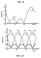
Curve 120 of Fig. 9 shows the amplitude response of port A in Fig. 8 when input ports A′, B′, C′ and D′ ofmatrix 110 are fed with a set of input signals defined by:
where Ψ is varied from 0 to 2 pi. (In the usual frequency scan technique, the input phase value Ψ is some function of frequency and is not necessarily constant.) Port A′ corresponds to n = 0, port B′ to n = 1 and so forth. Note that at a particular phase distribution a maximum signal level occurs at port A. Figure 10 shows the magnitudes of the output signals on all ports when thematrix 110 is fed with the same type of signal sequence described above.Curves matrix 110 is fed with the same type of signal sequence described above.Curves curve 120 associated with port A is of its maximum atpoint 128, curves 122-126 are at zero amplitude atpoint 130. Further analysis shows that the phase center of the antenna array attached to the output of the Butler matrix (as illustrated in Fig. 11) will scan the length of the array 40 (or 50) as a function of Ψ. Different frequencies result in different phase centers of the antenna array. - The performance of an antenna system employing a Butler matrix is affected by the number of elements used. The more elements used the better the spatial sampling of the input and output signal sequences. Thus, it will be appreciated that a Butler matrix with relatively few ports performs a rough approximation of a discrete Fourier transform (or inverse discrete Fourier transform) on signals passing therethrough. As the number of ports increases, the quality and accuracy of the transformation performed increases.
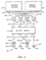
- Fig. 11 illustrates in greater detail how the
Butler matrix 110 may be used in anantenna system 138 of the present invention which includes transmitter and receiver subsystems. Thesystem 138 includes anarray 140 of feed elements orhorns 142 which are used both as radiating elements and receiving elements. Thehorns 142 may be of any conventional or suitable design, such as a cup dipole one wavelength in diameter. In practice, thehorns 142 function in the same basic manner as the radiating elements 42 (or 52) described earlier and are located at or very near the focal plane or plane of an offsetfeed reflector 32 as in the Fig. 6 arrangement. - The
system 138 also includes agroup 144 ofdiplexers 146, a receivenetwork 148 and a transmitnetwork 150 which are respectively connected to thediplexers 146 bygroups diplexers 164, however, we prefer to use diplexers of the type fully described in commonly assigned U.S. Patent No. 4,427,953 to T. Hudspeth and H. Keeling entitled "MICROWAVE DIPLEXER." Thediplexers 146 serve to properly route incoming signals in the uplink frequency band (received by theantenna array 140, transformed by thematrix 110, and impressed upon conductors of conductor group 156) to the receivenetwork 148. Similarly, thediplexers 146 serve to route the set of signals in the downlink frequency band (generated by the transmitnetwork 150 and impressed upon conductor group 154) to theButler matrix 110 where they are transformed and impressed onconductor group 158 for delivery to theantenna array 140. Note that in Fig. 11 the output of ports B and C of theButler matrix 110 is reversed in order to obtain a continuous scan of the virtual phase center with frequency. This is accomplished by having port B Connected byconduit 158b to feedhorn 142c and having port C connected via conduit 58c to feedhorn 142b as shown. The need to reverse the outputs of the beam ports B and C is clear when one observes that in Fig. 10 thecurves Butler matrix 110. - Fig. 12 is a block diagram for one possible embodiment which shows the various components and signal paths of the receive
network 148 ofantenna system 138 in Fig. 11. Thenetwork 148 includes: agroup 160 ofpreamplifiers 162 for boosting the level of the received signals delivered byconduits 152; agroup 164 offrequency translators 166 for reducing the carrier frequency of received signals frompreamplifiers 162 to an intermediate or baseband frequency range; agroup 168 of fourbandpass filters 170 for rejecting side lobes or other frequency translation products outside of the desired frequency range; and agroup 172 of three shift-producing components orelements 172, all connected together as shown to produce a baseband signal on output terminal orport 176. Theshift producing elements 174 may either be time delay elements or frequency-dependent phase shif ters. Thereceiver network 148 is tuned to the frequency bands of the respective uplink communication channels, thereby permitting simultaneous reception of signals from a plurality of ground stations. - Fig. 13 is a block diagram of the transmit
network 150 shown in Fig. 11. Thenetwork 150 includes: agroup 180 of shift-producing components orelements 182; agroup 184 of fourfrequency shif ters 186 for increasing the carrier frequency of signals imposed on group ofconduits 188 to a higher frequency range, agroup 190 ofbandpass filters 192 for removing unwanted signals outside of the desired frequency range generated by theoperation frequency translators 186; and agroup 194 ofpower amplifiers 196 to boost the power of the signals impressed onconductor group 154. In the transmitnetwork 150, the signal to be transmitted is imposed upon input terminal orport 198. - Figs. 12 and 13 also illustrate one possible method for producing the port-to-port input phase value Ψ as a function of frequency through the introduction of time delays or frequency-dependent phase shifts. These are introduced through the shift-producing
elements 174 in Fig. 12 and the shift-producingelements 182 in Fig. 13. In Fig. 13, the time delays or phase shifts are introduced at baseband (or some intermediate frequency), and then each signal in the resultant signal set is imposed on a conduit ofconduit group 188 in order to be frequency-translated in parallel byfrequency translators 186 up to the desired frequency range. This is done so that a particular bandwidth will produce the desired range of phase distributions in the signal set applied to theButler matrix 110 throughconductor group 154 and therefore result in the scanning of the phase center of the array across to the desired range. This method can be advantageously applied, for example, in the MAST system discussed in the background portion of the specification. - The MSAT system satellite discussed above will transmit in the UHF band at 866 to 870 MHz (or in the L-band if desired). The change in phase of a sinusoid due to a time delay such as those in Figs. 12 and 13 can be calculated by the following formula where input phase value is expressed in radians:

In order to produce a sufficiently large beam scan angle when using theButler matrix 110 shown in Fig. 8, a fairly wide range of phase distributions is required. - One approach for determining what time delays or phase shifts are required to operate the
system 138 of Fig. 11 in the desired manner is to choose the optimum range of phase distributions and find a frequency at which the bandwidth in question will produce this range using a time delay or phase shifting device. For example, theButler matrix 110 shown in Fig. 8 will provide the best scanning of the phase center of the antenna array if the input phase distributions range between π/4 and 7π/4 radians. For simplicity, assume a time delay will be used. Hence, setting the conditions:
and
then
or
Combining this relationship with the idea that
i.e., in the bandwidth of downlink transmissions in the MAST satellite, we can find that f₁ = 666.7 x 10³ Hz and f₂ = 4.6667 x 10⁶ Hz. Working at this intermediate frequency range, we can now find a time delay that will produce the desired range of phase distributions, namely τ = 1/(8f₁) = 187.5 x 10⁻⁹ seconds. Working with this time delay at this intermediate frequency band allows the bandwidth of the signal to produce the desired port-to-port frequency-dependent phase relationships. Each signal in the set can then be frequency-translated up to the desired frequency range (in parallel) without changing the port-to-port phase relationship introduced by the time delays at the intermediate frequency band. - By using different time delays and different intermediate frequencies, the signals from different transmitters (or to different receivers) may be combined to use the same Butler matrix and produce the same type of antenna patterns, even if the transmitters are operating at different frequencies and have different bandwidths. Using the technique described above, different signals with different bandwidths may be used to produce sets of input signals with the same range of phase distributions. Applying the combination of these sets to the Butler matrix feeding an antenna array allows both signal bandwidths to produce the same frequency scanned virtual beam patterns. This concept is illustrated in Fig. 14 which shows a dual-frequency transmit
network 210 capable of generating two sets of output signals at different frequency bands. Thenetwork 210 may be used in place of transmitnetwork 150 in theantenna system 138 shown in Fig. 11. - The
network 210 includes a firstfrequency network portion 212, a secondfrequency network portion 214, and acommon network portion 216.Network portion 212 is comprised of agroup 180 of three shift-producingdevices 182 and agroup 184 offrequency translators 186 which operate as previously explained in Fig. 13.Network portion 214 includes agroup 222 of shift-producingdevices 224 and agroup 226 offrequency translating devices 228 for producing a set of signals at a different frequency band from those produced bynetwork portion 212. The shift-producingdevices Network portion 216 includes: a group 230 of sum-producing elements or mixers 232 (which combine the two different sets of signals fromnetwork portions mixers 232 viaconductor groups group 190 of band pass filters 192; and agroup 194 ofpower amplifiers 196. The various components ofnetwork 210 are connected as shown in Fig. 14 and result in the production of two sets of signals having different frequency bands which are combined, amplified and then simultaneously impressed uponconductor group 154 for delivery to the remainder of thesystem 138 shown in Fig. 11. - The shift-producing units or
devices power amplifiers - To summarize at this point, the steerable beam antenna system described above provides a significant reduction in satellite weight by eliminating one of the two confocal parabolic reflectors which are used to provide two-way communications between ground stations and a geosynchronous satellite. Also provided is a technique for combining the power of output signals from several individual amplifiers operated in parallel into an individual one or small group of feed elements so as to more efficiently produce a stronger spot beam in a given location within the target area. In addition, the system described above provides for a technique wherein several antenna elements are used for both receiving and transmitting electromagnetic radiation. By providing two functions with several common elements, weight, space and cost of the satellite are reduced.
- Although the antenna system described above is highly effective, it produces beams which, at the outer edges of the target area, have undesirably high side lobes. The present invention, however, provides a solution to this problem, and in this connection reference is now made to Fig. 15, wherein a
Butler matrix 110 is shown having four inputs a′, b′, c′, and d′ and four outputs a, b, c, and d. TheButler matrix 110 is comprised of four 90°phase lead hybrids 112 and two negative 45° phase shif ters 114 interconnected as shown. The outputs of the Butler matrix a-d are routed to feed elements 116-119. The feed elements 116-119 deliver the electromagnetic radiation to a confocal reflector (not shown) which reflects and redirects the radiation to the target area. Outputs a and d are routed through 180° phase shif ters 115 before they deliver the outputs of their respective Butler matrix ports to their respective feed elements. As previously disclosed, theButler matrix 110 is used to perform a spatial discrete Fourier transform on the incoming signals a′-d′ to produce a focal plane field distribution equivalent to the common focal plane distribution in a dual confocal reflector system. If the Butler matrix feed arrangement as shown in Fig. 15 is used, some undesirably high side lobes will be present in the scanning beam whenever it scans towards the edge of the target area as mentioned above. The presence of these undesirable side lobes can be explained by referring to Fig. 16. - Shown in Fig. 16a is a hypothetical amplitude distribution which may be applied to
Butler matrix 110 via its input ports a′-d′. This hypothetical amplitude distribution will be used as a reference in discussing the output distributions shown in Figs. 16b-16e. As can be seen in Fig. 16a, the input distribution maintains a constant amplitude from port-to-port and a constant port-to-port phase gradient. Fig. l6b shows the output that would be present on feed elements 116-119 if the input to theButler matrix 110 was fed by four constant amplitude signals which shared a constant phase gradient of -45°. Note that for this hypothetical input phase gradient, all of the power radiated from horns 116-119 would be output fromport 2. Assuming that a phase gradient of 45° was presented to the signals that were input to theButler matrix 110, Fig. 16c shows that all of the power output from theButler matrix 110 would be output fromport 3, and no power would emanate fromports electrical phase center 300 of the array for the input phase gradient of 0°. Fig. 16e shows the output of the Butler matrix for an input phase gradient of 90°. Note that like Fig. 16d, each of the ports contributes some power to the overall output of the array, and that there is a 180° phase reversal on left-side port 2. Shown at 302 in Fig. 16e is the approximate location of the electrical phase center of the array for an input phase gradient of 90°. - The case in Fig. 16e illustrates the presence of undesirable side lobes for an input phase gradient of 90°. In this case, unlike the cases in Figs. 16b-16d, the excitation of the horns 116-119 is asymmetric about the electrical phase center of the array. This asymmetry in the feed excitations causes an asymmetry in the beam patterns for these intermediate beam positions which occur near the edge of the array. In other words, as the electrical phase sensor of the array scans towards the edge of the array, the beam shape degrades or dilates. This dilation is undesirable because in order to accommodate it, the system bandwidth and consequently system capacity must be sacrificed. A novel approach has been developed and is herein disclosed for eliminating this beam dilation. This novel approach will now be described in conjunction with Fig. 17.
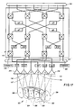
- Now referring to Fig. 17, a standard eight-
port Butler matrix 110 is shown having eightinput ports 310 and eightoutput ports 312. Eight-port Butler matrices of this nature are well-known to those in the art of satellite communications. Four of the outputs of the eight-port Butler matrix 116-119 are shown terminated at output feeds 1-4. This correlates to the arrangement used in Fig. 15. Two of the remaining outputs from the Butler matrix are terminated into output feeds which flank output feeds 116-119 and are shown as output feeds 314 and 316. The remaining two outputs of the Butler matrix are terminated into thenon-radiating load elements - The novel technique disclosed herein for eliminating the undesirable dilation of the arrayed beam involves using additional feed elements in the following unique manner. As can be seen from Fig. 17, primary feed elements 116-119 adequately cover the target area (continental United States) 322. Antenna feeds 314 and 316 are used to flank the primary feeds and to create beam patterns that do not concentrate their energy on the target area. This is illustrated in Fig. 17 by noting that the beam pattern projected by
feed element 314 does not in fact fall upon the continental United States. Likewise, the beam pattern emanating fromfeed element 316 is shown off of the east coast of the continental United States and predominantly falling within the Atlantic Ocean. Note that the reflector has been omitted from Fig. 17 for the sake of clarity and explanation, but would in fact be employed in a normal working system. - The primary beams 324-330 fall upon the target area generally along a common axis. These beams emanate from the feed elements 116-119 and are used to transmit information throughout the target area. The outer feeds 314 and 316 are used only for beam shaping and consequently are not used for information transmission. In Fig. 17,
beam patterns element beam Feeds feeds - Although two of the outputs of the
Butler matrix 110 are shown in a terminatedstate feed elements Butler matrix 110 were used, the system's overall ability to eliminate beam dilation would be even greater than it is when only six of the outputs of theButler matrix 110 are used. Terminating the two outputs as shown in Fig. 17 introduces a small power loss. For the case illustrated in Fig. 17, if the input phases are restricted such thatbeams element 116, then .0732 watt would be dissipated in the loads shown at 318 and 320. If all eight ports of theButler matrix 110 are used for beam shaping, this loss will not occur. - The foregoing embodiments of the present invention have been described with respect to a mobile satellite communications system for transmitting and receiving between multiple ground stations at certain specified frequencies in the L band. Those skilled in the art will appreciate that the present invention may be readily adapted for use in land or satellite communication systems operated in other frequency bands, such as the C or Ku bands, for example. The number of additional radiating elements, which are added to eliminate side lobes, is not limited to one or two. Any number of additional radiating elements may be added, each of which will act to further reduce undesirable side lobes. The size of the main reflector, the arrangement and type of antenna arrays, and the specific receive and transmit networks utilized in the present invention may vary substantially without departing from the scope of the broader aspects of the present invention. For example, separate feed horns may be used to transmit and receive electromagnetic radiation constituting the steerable beam. Also, a conventional screen-type diplexer may be placed between the antenna array and reflector so as to divert the incoming electromagnetic radiation to be received to a separate receiver array arranged at a substantial angle to the plane of the first antenna array. Such an embodiment would thus have separate transmit and receive antenna arrays. Alternatively, two separate main reflectors could be provided, one to be used with a separate transmit antenna array and the other to be used with a separate receive antenna array. We presently do not favor this latter arrangement for satellite antenna systems of the present invention on account of the appreciable extra weight and cost of providing two main reflectors. However, such an embodiment may be quite suitable for systems of the present invention constructed on land or on sea-going vessels.
- In view of the foregoing description, it is seen that the antenna system of the present invention is well-suited for two-way communications between ground stations and a geosynchronous satellite. The antenna system of the present invention has the advantages of effectively combining the power of the output signals of a plurality of power amplifiers simultaneously operated in parallel. It also provides a single reflector antenna system which, through the use of a spatial transformation means such as a Butler matrix, is functionally equivalent to the dual confocal reflector system described in the background portion of the specification, including achieving a magnification of the effective aperture of the elements. The antenna system of the present invention eliminates the need for the use of a subreflector without providing additional radiating elements, thus saving weight, space and cost. Since the antenna system of the present invention uses a scannable virtual beam technique, it also reduces the physical size of the antenna system by minimizing the number of radiating elements and reflectors which must be used. The present system also acts to reduce the undesirable side lobes that occur as the radiated beam scans towards the edge portions of the target area. This side lobe suppression is achieved by placing additional radiating elements along with the main array and using the additional radiating elements to produce beams of energy which cancel the undesirable side lobes which accompany the primary beams. Thus, an antenna system of the present invention results in a lighter weight, more efficient satellite communication system. Finally, the use of time delays or phase shifts at baseband or intermediate frequencies allows the output of multiple transmit networks to be applied to a single array of radiating elements to produce the same antenna pattern at different frequencies, thus enabling the antenna system to be used in satellite communication systems requiring a multiple, two-way, simultaneous communication channel between many widely separated ground stations within the scanning angle of the virtual beams.
Claims (20)
- An antenna system comprising:
a reflector (32) having a focal point (F) associated therewith;
an antenna array having a plurality of radiating elements (116,117,118,119) and responsive to signals provided thereto for producing beams (324,326,328,330) of electromagnetic radiation used for information transmission and covering a target area, wherein said array is operatively disposed near the focal point (F) of said reflector and at least certain of said antenna beams including undesirable side lobes;
means (110) operatively connected to said antenna array for performing an approximate spatial transformation on the amplitude and phase distribution of said signals provided to said antenna array
characterized by
at least one additional radiating element (314,316) positioned along with said array (116,117,118,119), said additional radiating element (314,316) being operatively disposed near the focal point (F) of said reflector;
said additional radiating element (314,316) being responsive to said signals to produce a first additional beam (332,334) of electromagnetic radiation, not used for information transmission, and having a center portion falling outside of said target area and a fringe portion overlapping at least a first portion of said target area, said fringe portion of said first additional beam (332,334) combining with said certain of said antenna beams (324,326,328,330) to reduce said side lobes and
said means (110) for performing approximate spatial transformation on amplitude and phase distribution is also operatively connected with said additional radiating element (314,316) to perform a transformation to the signals provided to the additional radiating element (314,316). - A system as in claim 1, wherein each of said radiating elements (314,316) is a feed horn arranged in a hexagonal pattern.
- A system as in claim 1, wherein said approximate spatial transformation means (110) is a Butler matrix having a plurality of input ports and a plurality of output ports.
- A system as in claim 3, wherein said output ports of said Butler matrix are connected to said at least one additional radiating element (314,416) and said radiating elements (116,118,119) of said antenna array and wherein said spatial transformation is a discrete Fourier transformation.
- A system as in claim 4, further including means for feeding said input ports of said Butler matrix with a set of signals having a predetermined phase relationship defined by the formula:

- A system as in claim 5, wherein the input phase value Ψ varies as a function of frequency ω.
- A system as in claim 3, further including:
first means (150,212,214) for generating from a first signal having a first nominal frequency, a first set of second signals shifted in phase from one another for delivery to said transformation means in order to enable said system to produce a frequency scanning virtual beam containing information encoded in said first signal. - A system as in claim 7, wherein said first means for generating includes a plurality of phase shift-producing elements (174,182,224), each capable of effectively phase-shifting a signal passed therethrough and each being associated with one of said second signals.
- A system as in claim 8, wherein each phase shift-producing element (174,182,224) is a time delay device.
- A system as in claim 3, wherein certain of said output ports are respectively connected to said radiating elements (116,117,118,119) and said one additional radiating element (314,316) and at least one other of said output is connected to a nonradiating load.
- A system as in claim 1, wherein said beams (322,324, 326,328) and said one additional beam (332,334) are substantially aligned along a common reference axis at the respective points of impingement of said beams on said target area.
- A system as in claim 1, including a second additional radiating element (314,316) positioned along with said array and spaced apart from said one dditional radiating element, said second additional radiating element (314,316) being operatively disposed near the focal point of said reflector and responsive to said signals to produce a second additional beam (332,34) of electromagnetic radiation notused for information purposes having a center portion falling outside of said target area and a fringe portion overlapping at least a second portion of said target area spaced from said first portion of said target area, said fringe portion of said second additional beam combining with said certain of said antenna beams to reduce said side lobes.
- A system as in claim 1, wherein said beams (322,324, 326,328) and said first and second additional beams (332,334) are substantially aligned along a common reference axis at the respective points of impingement of the beams on said target area.
- A method of operating a steerable beam antenna system of the type including a reflector (32) having a focal point (F) and a plurality of radiating elements (116, 117,118,119) responsive to signals provided thereto, said plurality of radiating elements (116,117,118,119) being disposed generally at said focal point (F) of said reflector (32) and forming scanning beams (322, 324,326,328) of electromagnetic energy directed by said reflector at a target area to scan across and collectively cover said target area, said target area having at least one side wherein the scanning beams (322,324,326,328) used for information transmission which are directed to said one side include undesirably high side lobes of electromagnetic energy, comprising the steps of:(a) providing a set of first signals having a predetermined phase relationship with respect to each other and containing information to be transmitted;(b) generating a set of second signals from said set of first signals by at least approximately performing a spatial transformation on the amplitude and distribution of said set of first signals;(c) creating said scanning beam by transmitting preselected ones of said second set of signals towards said reflector by passing said preselected ones of said second set of signals through said plurality of radiating elements (116,117,118,119)
characterized by(d) creating at least one additional beam (332,334) by transmitting at least one signal in said second set of signals towards said reflector by passing said at least one signal through an additional radiating element (314,316) located along with said plurality of radiating elements, said additional beam being directed so that the center portion thereof falls outside of the target area, and the fringe portion of the additional beam falls upon said one side of said target area, said fringe portion of said additional beam combining with said scanning beam to reduce said side lobes to a desirable level, wherein said at least one additional beam is not used for information transmission. - A method as in claim 14, wherein step (b) is performed by using a Butler matrix (110) to generate said second set of signals from said set of first signals, and wherein said spatial transformation is discrete Fourier transformation.
- A method as in claim 14, wherein the predetermined phase relationship of said set of first signals is at least substantially defined by:

- A method as in claim 14, wherein step (a) includes the substeps of:(1) providing a baseband signal; and(2) introducing a plurality of time delays into said baseband signal to generate at least a plurality of said first signals.
- A method as in claim 14, wherein steps (c) and (d) are performed such that said scanning beam and additional beams impinge said target area along substantially a common axis.
- A method as in claim 14, including the step of creating a second additional beam (332,334) directed so that the center portion thereof falls outside the target area, and the fringe portion of said second additional beam combines with said scanning beam to reduce said side lobes to said desirable level, wherein said second additional beam is not used for information transmission.
- A method as in claim 19, wherein the first and second additional beams are directed so that said fringe areas thereof are spaced apart from each other.
Applications Claiming Priority (2)
| Application Number | Priority Date | Filing Date | Title |
|---|---|---|---|
| US43405989A | 1989-11-08 | 1989-11-08 | |
| US434059 | 1989-11-08 |
Publications (3)
| Publication Number | Publication Date |
|---|---|
| EP0427201A2 EP0427201A2 (en) | 1991-05-15 |
| EP0427201A3 EP0427201A3 (en) | 1991-12-11 |
| EP0427201B1 true EP0427201B1 (en) | 1995-08-30 |
Family
ID=23722654
Family Applications (1)
| Application Number | Title | Priority Date | Filing Date |
|---|---|---|---|
| EP19900121219 Expired - Lifetime EP0427201B1 (en) | 1989-11-08 | 1990-11-06 | Satellite beam-forming network system having improved beam shaping |
Country Status (5)
| Country | Link |
|---|---|
| EP (1) | EP0427201B1 (en) |
| JP (1) | JPH03172003A (en) |
| AU (1) | AU624742B2 (en) |
| CA (1) | CA2027456C (en) |
| DE (1) | DE69021993T2 (en) |
Families Citing this family (6)
| Publication number | Priority date | Publication date | Assignee | Title |
|---|---|---|---|---|
| CA2121587A1 (en) * | 1991-10-28 | 1993-05-13 | Edward Fenton Tuck | Satellite communication system |
| GB2288913B (en) * | 1994-04-18 | 1999-02-24 | Int Maritime Satellite Organiz | Satellite payload apparatus with beamformer |
| WO2012161612A1 (en) | 2011-05-23 | 2012-11-29 | Autonomous Non-Commercial Organization "Research Institute "Sitronics Labs"" | Electronically beam steerable antenna device |
| RU2530330C1 (en) | 2013-03-22 | 2014-10-10 | Общество с ограниченной ответственностью "Радио Гигабит" | Radio relay communication station with scanning antenna |
| RU2595941C2 (en) * | 2014-05-06 | 2016-08-27 | Общество с ограниченной ответственностью "Радио Гигабит" | Radio relay communication system with beam control |
| US9973266B1 (en) * | 2017-06-12 | 2018-05-15 | Ast & Science, Llc | System and method for high throughput fractionated satellites (HTFS) for direct connectivity to and from end user devices and terminals using flight formations of small or very small satellites |
Family Cites Families (3)
| Publication number | Priority date | Publication date | Assignee | Title |
|---|---|---|---|---|
| US4595929A (en) * | 1982-04-13 | 1986-06-17 | Communications Satellite Corporation | Scheme for aberration correction in scanning or multiple beam confocal antenna system |
| JPS60196003A (en) * | 1984-03-19 | 1985-10-04 | Nippon Telegr & Teleph Corp <Ntt> | Multi-beam antenna of low side lobe |
| WO1988004837A1 (en) * | 1986-12-22 | 1988-06-30 | Hughes Aircraft Company | Steerable beam antenna system using butler matrix |
-
1990
- 1990-10-12 CA CA 2027456 patent/CA2027456C/en not_active Expired - Fee Related
- 1990-10-17 AU AU64765/90A patent/AU624742B2/en not_active Ceased
- 1990-11-06 DE DE1990621993 patent/DE69021993T2/en not_active Expired - Fee Related
- 1990-11-06 EP EP19900121219 patent/EP0427201B1/en not_active Expired - Lifetime
- 1990-11-08 JP JP30375190A patent/JPH03172003A/en active Pending
Also Published As
| Publication number | Publication date |
|---|---|
| DE69021993D1 (en) | 1995-10-05 |
| CA2027456A1 (en) | 1991-05-09 |
| EP0427201A2 (en) | 1991-05-15 |
| EP0427201A3 (en) | 1991-12-11 |
| JPH03172003A (en) | 1991-07-25 |
| AU624742B2 (en) | 1992-06-18 |
| AU6476590A (en) | 1991-05-16 |
| DE69021993T2 (en) | 1996-02-22 |
| CA2027456C (en) | 1995-09-26 |
Similar Documents
| Publication | Publication Date | Title |
|---|---|---|
| US4882588A (en) | Steerable beam antenna system using butler matrix | |
| US5576721A (en) | Composite multi-beam and shaped beam antenna system | |
| US4972151A (en) | Steered-beam satellite communication system | |
| EP0963006B1 (en) | Reconfigurable multiple beam satellite phased array antenna | |
| US6456251B1 (en) | Reconfigurable antenna system | |
| US5557292A (en) | Multiple band folding antenna | |
| EP0395239B1 (en) | Antenna beam forming system | |
| US4872015A (en) | Satellite communications system for mobile users | |
| EP0294413B1 (en) | Steerable beam antenna system using butler matrix | |
| EP0466126B1 (en) | Method and apparatus for producing multiple, frequency-addressable scanning beams | |
| US6392611B1 (en) | Array fed multiple beam array reflector antenna systems and method | |
| US4232321A (en) | Multiple beam satellite antenna with preferred polarization distribution | |
| JPH0552099B2 (en) | ||
| JPH0728175B2 (en) | Hybrid communication satellite antenna system | |
| US5847681A (en) | Communication and tracking antenna systems for satellites | |
| JP3284837B2 (en) | Distribution combining device and antenna device | |
| US6374104B1 (en) | Frequency and polarization allocation for satellite telecommunication systems | |
| US4388626A (en) | Phased array antennas using frequency multiplication for reduced numbers of phase shifters | |
| EP0427201B1 (en) | Satellite beam-forming network system having improved beam shaping | |
| Reudink | Communications: Spot beams promise satellite communication breakthrough: Focused antenna beams with frequencies accessed by time division can mean higher uplink power and more powerful communication service | |
| JPH04220003A (en) | Expanded phased array equipped with digital beam forming circuit network | |
| Egami et al. | An adaptive multiple-beam transmitter for satellite communications | |
| Thompson et al. | Frequency addressable beams for land mobile communications | |
| Teshirogi et al. | Multibeam array antenna for data relay satellite |
Legal Events
| Date | Code | Title | Description |
|---|---|---|---|
| PUAI | Public reference made under article 153(3) epc to a published international application that has entered the european phase |
Free format text: ORIGINAL CODE: 0009012 |
|
| AK | Designated contracting states |
Kind code of ref document: A2 Designated state(s): DE FR GB IT |
|
| PUAL | Search report despatched |
Free format text: ORIGINAL CODE: 0009013 |
|
| AK | Designated contracting states |
Kind code of ref document: A3 Designated state(s): DE FR GB IT |
|
| 17P | Request for examination filed |
Effective date: 19920109 |
|
| 17Q | First examination report despatched |
Effective date: 19940223 |
|
| RAP1 | Party data changed (applicant data changed or rights of an application transferred) |
Owner name: HUGHES AIRCRAFT COMPANY |
|
| GRAA | (expected) grant |
Free format text: ORIGINAL CODE: 0009210 |
|
| AK | Designated contracting states |
Kind code of ref document: B1 Designated state(s): DE FR GB IT |
|
| PG25 | Lapsed in a contracting state [announced via postgrant information from national office to epo] |
Ref country code: IT Free format text: LAPSE BECAUSE OF FAILURE TO SUBMIT A TRANSLATION OF THE DESCRIPTION OR TO PAY THE FEE WITHIN THE PRESCRIBED TIME-LIMIT;WARNING: LAPSES OF ITALIAN PATENTS WITH EFFECTIVE DATE BEFORE 2007 MAY HAVE OCCURRED AT ANY TIME BEFORE 2007. THE CORRECT EFFECTIVE DATE MAY BE DIFFERENT FROM THE ONE RECORDED. Effective date: 19950830 Ref country code: FR Free format text: LAPSE BECAUSE OF NON-PAYMENT OF DUE FEES Effective date: 19950830 |
|
| REF | Corresponds to: |
Ref document number: 69021993 Country of ref document: DE Date of ref document: 19951005 |
|
| PGFP | Annual fee paid to national office [announced via postgrant information from national office to epo] |
Ref country code: FR Payment date: 19951009 Year of fee payment: 6 |
|
| PGFP | Annual fee paid to national office [announced via postgrant information from national office to epo] |
Ref country code: GB Payment date: 19951017 Year of fee payment: 6 |
|
| PGFP | Annual fee paid to national office [announced via postgrant information from national office to epo] |
Ref country code: DE Payment date: 19951023 Year of fee payment: 6 |
|
| EN | Fr: translation not filed | ||
| PLBE | No opposition filed within time limit |
Free format text: ORIGINAL CODE: 0009261 |
|
| STAA | Information on the status of an ep patent application or granted ep patent |
Free format text: STATUS: NO OPPOSITION FILED WITHIN TIME LIMIT |
|
| 26N | No opposition filed | ||
| PG25 | Lapsed in a contracting state [announced via postgrant information from national office to epo] |
Ref country code: GB Effective date: 19961106 |
|
| GBPC | Gb: european patent ceased through non-payment of renewal fee |
Effective date: 19961106 |
|
| PG25 | Lapsed in a contracting state [announced via postgrant information from national office to epo] |
Ref country code: DE Effective date: 19970801 |