EP0421964B1 - A method of communication in mobile radio systems - Google Patents
A method of communication in mobile radio systems Download PDFInfo
- Publication number
- EP0421964B1 EP0421964B1 EP90850305A EP90850305A EP0421964B1 EP 0421964 B1 EP0421964 B1 EP 0421964B1 EP 90850305 A EP90850305 A EP 90850305A EP 90850305 A EP90850305 A EP 90850305A EP 0421964 B1 EP0421964 B1 EP 0421964B1
- Authority
- EP
- European Patent Office
- Prior art keywords
- channels
- radio
- calls
- allowed
- mobile
- Prior art date
- Legal status (The legal status is an assumption and is not a legal conclusion. Google has not performed a legal analysis and makes no representation as to the accuracy of the status listed.)
- Expired - Lifetime
Links
Images


Classifications
-
- H—ELECTRICITY
- H04—ELECTRIC COMMUNICATION TECHNIQUE
- H04W—WIRELESS COMMUNICATION NETWORKS
- H04W16/00—Network planning, e.g. coverage or traffic planning tools; Network deployment, e.g. resource partitioning or cells structures
- H04W16/02—Resource partitioning among network components, e.g. reuse partitioning
- H04W16/10—Dynamic resource partitioning
-
- H—ELECTRICITY
- H04—ELECTRIC COMMUNICATION TECHNIQUE
- H04W—WIRELESS COMMUNICATION NETWORKS
- H04W16/00—Network planning, e.g. coverage or traffic planning tools; Network deployment, e.g. resource partitioning or cells structures
- H04W16/14—Spectrum sharing arrangements between different networks
Definitions
- This invention relates to mobile radio systems.
- the invention relates to a method of communication in at least one mobile radio system with dynamic channel allocation in an environment of additional mobile radio systems with dynamic channel allocation and mobile stations capable of cooperation with more than one of the systems.
- the small cells sizes open up possibilities to use very light weight pocket communication sets and at the same time provide extremely high traffic densities on a limited amount of spectrum.
- DCA is also shown to be at least twice as frequency efficient as procedures with fixed frequency planning. Especially the TDMA in DCT and DECT gives very quick efficient and elegant procedures for DCA, flexible capacity, call set up and handover, without any need for complicated central control.
- a first example is self organizing sharing and market driven capacity for systems performing to the same coexistance specification.
- the basic advantage is that different systems and system operators and different type of service (e.g. business, telepoint, residential) in a self organizing way, can utilize the same lump of available channels without prior distribution of channels to specific services or base stations.
- each service provider can, driven by the market development, increase the capacity by increasing his base station density.
- a second example is radio links and a cordless telephone system, DCT, with DCA.
- the radio links can be fixed or mobile, military or civil.
- No cordless telephones, CT are excepted to be in the link beam.
- the power of the CT is low, max 100 mW.
- the radio links are not supposed to be interferred by the CT's.
- the possible interference from the radio links to the CT's will be very local. If the links are military, you do not know where or when or on which exact frequency the interference will occur.
- a CT like DCT, with several 1 MHz carriers, will with DCA, adjust locally to the useful carriers.
- DCT and radio links can coexist well, without detailed prior knowledge of the local situation.
- DCA Due to the nature of DCA it is good not to depend on a fixed or special signalling channel e.g. for system information to provide means for a roaming portable to connect to the system. Because that signalling channel has not guaranted protection against interference, and a fixed channel would spoil the concept of free DCA. It is also not good, if a portable which does not know on which channels his wanted system is operating on, pollutes the air in more or less blind trials to get a response from it.
- a portable may be able to operate on the whole available frequency band, but different countries have not been able to free the whole band.
- part of the band may be occupied by a sensitive TV link.
- the fixed stations in this country can easily be programmed not to use that part of the band. But roaming portables must be prohibited to transmit in that part.
- U.S. 4.347.625 discloses an arrangement for inhibiting attempted communications on channels not in a selected cell even though the mobile stations are capable of operation on the channels of non-selected cells.
- a mobile is manually or automatically selecting a cell and is pre-programmed to operate only on radio channels available in the selected cell.
- the present invention gives a solution to the problem for a portable to find a wanted system, operating on an unknown part of the allocated band, and not start any transmissions without having received information on which channels are allowed to use, and on suitable call set up channel selection.
- each cell in every system is always active on at least one channel.
- at least one channel By letting at least one channel always be active on each fixed station of a system (the last communication channel stays on), a portable has always something to listen to in each cell.
- On every active cell a small part of the capacity is devoted for broadcasting system information regarding identity, channels used, order in which base station scans channels for incoming calls etc. This simplifies for a roaming portable to find the system, and quickly synchronize and connect to it without polluting the air with a number of more or less well targeted transmissions trying to find it.
- a method according to the invention means that telecommunication systems with dynamic channel allocation operatable over a relatively wide band (10-20Mhz) have large advantages in that different services and systems can operate on the band without prior frequency planning and distribution of different channels to different users or services or systems. Every system adjusts to the local situation and choses channels that for the time being are free.
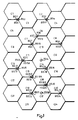
- Fig 1 illustrates a cellular mobile radio system in an environment of a plurality of other cellular mobile radio systems.
- Fig 2 illustrates a mobile radio station for communication with fixed radio stations in a cellular mobile radio system.
- Fig 3 illustrates a fixed radio station for communication with mobile radio stations in a cellular mobile radio system.
- Figure 4 illustrates the transmission of digital information divided into blocks or fields.
- Figure 5 and 6 illustrates embodiments of subdivision of one of the blocks or fields of a transmission according to figure 4.
- Figure 7 illustrates a TDMA radio channel frame with 16 time slots.
- Figure 8 illustrates the structure of transmission in a time slot of a TDMA frame according to figure 7.
- Figure 9 illustrates embodiments of a C-field in a time slot according to figure 8 for a normal slot, a paging slot and a system information slot, respectively.
- Figure 10 illustrates an alternative embodiment of a C-field of a time slot according to figure 8.
- Illustrated in figure 1 are a plurality of cells C1 to C24.
- a base station BS1 to BS24 for communication with mobile stations.
- the cells and corresponding base stations BS1 to BS24 may constitute parts of one or more cellular mobile radio systems.
- cells C1 to C8 and base stations BS1 to BS8 may belong to a first system
- cells C10 to C17 and base stations BS10 to BS17 may belong to a second system
- cells C18 to C24 and base stations BS18 to BS24 may belong to a third system.
- Each mobile radio system also comprises at least one mobile switching centre MSC or base station controller BSC not illustrated in figure 1.
- MSC mobile switching centre
- base stations BS1 to BS24 those belonging to one system are connected to a mobile switching centre or base station controller of that system, e.g. by cables or fixed radio links not illustrated in figure 1.
- base stations BS1 to BS8 may be connected to a first mobile switching centre MSC1
- base stations BS10 to BS17 may be connected to a second mobile switching centre MSC2
- base stations BS18 to BS24 may be connected to a third mobile switching centre MSC3.
- Illustrated in figure 1 are also a plurality of base stations XS6, XS7, XS10, XS11, XS13, XS15A, XS15B, XS18A, XS18B, XS19, XS20, XS22A and XS22B belonging to a particular mobile radio system also serving the cells C6, C7, C10, C11, C13, C14, C15, C18, C19, C20 and C22.
- the base stations XS6, XS7, XS10, XS11, XS13, XS15A, XS15B, XS18A, XS18B, XS19, XS20, XS22A and XS22B are all connected by cables or radio links to a particular mobile switching centre MSCX, not illustrated in figure 1.
- the mobile radio systems of base stations BS1 to BS24 and XS7 to XS22B and cells C1 to C24 are all digital TDMA systems where the base stations and the served mobile stations transmit and receive radio signals in time slots on a plurality of radio channels.
- Mobile stations served by the systems are designed for operation on any of a plurality of radio channels in a predetermined group of radio channels. For various reasons, however, not all of the systems are capable or allowed to operate on any of the radio channels in the predetermined group of radio channels.
- the first and third systems comprising BS1 to BS8 and BS18 to BS24 may both be capable and allowed to operate on all radio channels in the predetermined group.
- the second system comprising the base stations BS10 to BS16 may not be capable of operation on all of the radio channels in the predetermined group but only be capable of operating on a second subgroup.
- the particular system may be capable of operating on all radio channels in the predetermined group but not allowed to operate on some of the radio channels in order to avoid interference with other radio communication.
- None of the mobile radio systems comprising the cells C1 to C24 illustrated in figure 1 have a fixed frequency reuse plan with fixed allocation of channels to cells and base stations. Instead all of the systems comprising the cells C1 to C24 practice dynamic channel allocation. Due to the dynamic channel allocation none of the systems have a radio channel exclusively reserved for access or paging or control purposes but paging of mobile stations and system information for roaming mobiles etc are transmitted on the radio channels for calls.
- Figure 2 illustrates a block diagram of a mobile station
- figure 3 illustrates a block diagram of a base station for use in any of the cellular mobile radio systems according to figure 1 in connection with a method according to the present invention.
- the base and mobile stations are designed for transmission of bursts in time slots of a selected communication radio channel that is shared by plural stations in time multiplex and for receiving bursts transmitted by other stations in such time slots.
- the time slots may be used e.g. substantially for a normal full duplex telephone call or substantially for digital message communication or for both simultaneously.
- a base station normally comprises means enabling it to simultaneous transmission and reception on more than one selectable radio channel
- the apparatus required for simultaneous transmission and reception on plural radio channels are substantially duplicates of the apparatus for one selectable radio channel and for reasons of space only means for communication on one selectabel radio channel at a time are illustrated in figure 3.
- Both base and mobile station comprise a micro processor controlled radio transmitter (including modulator) and a microprocessor controlled radio receiver (including demodulator).
- the radio transmitter transmits radio signals modulated with digital signals from a burst generator.
- the burst may comprise audio signals from an audio signal processing means and digital messages generated by a message generator.
- the audio signal processor is connected to an audio information source, e.g. a microphone, while the message generator is connected to a data information source, e.g. a keyboard, via a data information buffer.
- the audio signal processing means is instead connected to an audio line terminal receiving audio information from the MSC to which the audio terminal is connected by radio link or cables.
- the message generator of the base is via a data information buffer connected to a data line terminal receiving data from the MSC to which the data line terminal is connected by radio link or cables.
- the radio receiver of base and mobile is connected to a an analog to digital converter and possibly also an optional equalizer.
- the analog to digital converter and optional equalizer is connected to a message decoder for detecting messages in received bursts and to an audio output processor for audio information in received bursts.
- the message decoder is connected to a data information output means, e.g. a display, via a data information buffer, while the audio output processor is connected to an audio information output means, e.g. a loudspeaker.
- a data information output means e.g. a display
- the audio output processor is connected to an audio information output means, e.g. a loudspeaker.
- the message decoder is instead connected via a data information buffer to a data line terminal supplying data to the MSC to which the data terminal is connected by radio link or cables, while the audio output processor is connected to an audio line terminal supplying audio information to the MSC to which the audio line terminal is connected.
- the radio channel on which the base or mobile radio transmitters and receivers operate is determined by frequencies supplied from a frequency synthesizer controlled by the microprocessor.
- the base and mobile comprises data store means for storing information on the particular system, base and mobile station, radio channels, frame and time slot format, message formats, error protecting codes, algorithms for operation of station etc.
- the microprocessor is connected to the store and almost all blocks for controlling and timing their operation, for supplying information, e.g. from the store, to be incorporated in bursts to be transmitted, and for receiving information from received bursts, e.g. for control purposes or for storing in the store.
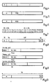
- Figure 4 illustrates a transmission from a base or mobile station.
- the digital transmission is generally divided into some kind of blocks each having synchronization bits, S, a control field, C, and an information field for speech or data, I.
- Fig 5 illustrates a C field.
- the C field contains header, H, fixed station identity, FSID, and some other information.
- An idle unlocked portable can regularily scan all available channels and if within reach of a cell he will detect an active channel and if FSID is the ID of a system it wants to connect to, the portable will lock itself on this channel.
- Every portable within reach of a wanted system is in locked idle mode and is locked to an arbitrary (strongest) active channel on any of the base stations.
- the header, H is changed, and FSID is exchanged with a portable station ID, PSID, in the C field of every active channel.
- Figure 6 illustrates such a C field when broadcast paging is transmitted.
- the new problem that has to be solved is for roaming portables, when it is not known on which set of channels the system operates. It is also probable that a fixed station does not have enough receivers to listen simultaneously on all free channels for an incoming call (no special signalling channel exists). Thus the portable also needs information on in which order scanning of free channels are made, in order to avoid polluting with blind connection trials.
- the invention proposes that required additional system information is broadcasted on every active channel, and that no portable is allowed to transmit before it has locked to an active channel and received this system information.
- the FSID is also a system information, but it has to be sent regularly, because PS in idle lock or in communication regularily checks the field strenght and the identity of other active channels. if transmission from an other own FS is stronger than the own FS, an handover is made to the new FS.
- the SI information shall contain the following information:
- the invention is applicable to different kind of radio multiple access methods FDMA or TDMA for instance.
- FIG. 7 illustrates such a TDMA radio channel frame with 8 times slots for transmission in the direction from portable (mobile) to fixed (base) station and 8 time slots for transmission in the direction from fixed to portable station.
- Figure 8 illustrates the structure of a time slot in a TDMA frame according to figure 7.
- the number of bits transmitted in a burst in the slot is indicated.
- CRC are check bits and G is guardspace to next slot.
- the carried speech or data is in the information field I.
- the C field will contain different information following different 6 bit headers as illustrated in figure 9 for a normal slot, a paging slot and a system information slot.
- Figure 9 also illustrates examples of C-field information.
- the SI information can e.g. look;
- All active slots normally have the Normal in the C-field. That is exchanged to paging, when broadcast paging is needed, and to system information when SI is broadcasted. SI is as earlier mentioned not needed very often, perhaps every 16th or 32th frame corresponding to every quarter half second.
- Reference and order of scanning free channels at FS is especially applicable when the FS is a single radio tranceiver for 8 duplex slots TDMA and can change carrier from slot to slot.
- the receiver of this base station can only scan for incoming calls on free channels at one time slot at a time, and will scan all time slots on one carrier and than all on the next carrier etc.
- the FS will scan the carriers in order.
- the reference tell which carrier in scanned during the actual frame. To get quicker access time the FS can have up to three parallell scanning receivers, starting at different references. 4 bits are needed per reference 0000,0000,0000 3 times 4 bits have been assigned. 0000 means no more parallell receiver.
- FIG. 10 illustrates a C-field with 2 SI bits. In this case after 16 frames, 256ms, all 32 SI bits have been transmitted.
- the broadcasted SI could in principle also contain other system information, as services available by the system and e.g. an FS dependent part telling which channels are regarded free at that specific FS. These are not included, since it is important to keep the broad casted information as short as possible, no to steel capacity. There are other better ways.
- the invention is not restricted to embodiments described.
- the invention is not restricted to descibed TDMA systems but may also be implenmented in FDMA systems.
Abstract
Description
- This invention relates to mobile radio systems. In particular the invention relates to a method of communication in at least one mobile radio system with dynamic channel allocation in an environment of additional mobile radio systems with dynamic channel allocation and mobile stations capable of cooperation with more than one of the systems.
- There are many kinds of cellular mobile radio systems. They may be grouped in various ways depending on various methods of operation. Of particular interest to the present invention is the method used for allotting a radio channel at call set up and handover and the interaction with adjacent or colocated other systems.
- Originally cellular mobile radio systems had fixed radio channel reuse plans with fixed allocation of radio channels to base stations and cells. Later on dynamic channel allocation was suggested.
- Dynamic Channel Allocation, DCA, has recently been acknowledged to be the only practical way to allocate channels for systems with very small cell sizes. Systems using DCA are for the time being mainly cordless telephone sets and systems, e.g.: CEPT CT-1: Analog FDMA/FDD 900 MHz. Existing Digital UK CT-2: FDMA/TDD 800 MHz. Interim '89, CAI-90 Swedish DCT: Digital Multicarrier (MC) TDMA/TDD 800 MHz 1990 ETSI DECT: Digital Multicarrier (MC) TDMA/TDD (1.6 GHz) 1992.
- The small cells sizes open up possibilities to use very light weight pocket communication sets and at the same time provide extremely high traffic densities on a limited amount of spectrum.
- DCA is also shown to be at least twice as frequency efficient as procedures with fixed frequency planning. Especially the TDMA in DCT and DECT gives very quick efficient and elegant procedures for DCA, flexible capacity, call set up and handover, without any need for complicated central control.
- Finally DCA adjusts to local conditions and thus opens up new possibilities for shared services. This has been emphasized in a report on Cordless Telephone Product by the European Commission.
- A first example is self organizing sharing and market driven capacity for systems performing to the same coexistance specification. The basic advantage is that different systems and system operators and different type of service (e.g. business, telepoint, residential) in a self organizing way, can utilize the same lump of available channels without prior distribution of channels to specific services or base stations. By having C/I limited cell range each service provider can, driven by the market development, increase the capacity by increasing his base station density.
- A second example is radio links and a cordless telephone system, DCT, with DCA. The radio links can be fixed or mobile, military or civil. No cordless telephones, CT, are excepted to be in the link beam. The power of the CT is low, max 100 mW. Thus the radio links are not supposed to be interferred by the CT's. The possible interference from the radio links to the CT's will be very local. If the links are military, you do not know where or when or on which exact frequency the interference will occur. A CT, like DCT, with several 1 MHz carriers, will with DCA, adjust locally to the useful carriers. Thus DCT and radio links can coexist well, without detailed prior knowledge of the local situation.
- Due to the nature of DCA it is good not to depend on a fixed or special signalling channel e.g. for system information to provide means for a roaming portable to connect to the system. Because that signalling channel has not guaranted protection against interference, and a fixed channel would spoil the concept of free DCA. It is also not good, if a portable which does not know on which channels his wanted system is operating on, pollutes the air in more or less blind trials to get a response from it.
- For a PAN European System for instance, a portable may be able to operate on the whole available frequency band, but different countries have not been able to free the whole band. In a specific country or part of a country, for instance part of the band may be occupied by a sensitive TV link. The fixed stations in this country can easily be programmed not to use that part of the band. But roaming portables must be prohibited to transmit in that part.
- Thus there is a need for recognition of channels used by a wanted system.
- An arrangement for the cellular operation of a repeater trunking system is described in U.S. 4.347.625. In a repeater trunking system including a plurality of mobile stations communicating over a predetermined number of communication channels, each associated with a repeater, U.S. 4.347.625 discloses an arrangement for inhibiting attempted communications on channels not in a selected cell even though the mobile stations are capable of operation on the channels of non-selected cells. A mobile is manually or automatically selecting a cell and is pre-programmed to operate only on radio channels available in the selected cell.
- Simulations and practical tests of digital cellular radio systems show that DCA works very well if the concept is designed without use of specific signalling channels. The present invention gives a solution to the problem for a portable to find a wanted system, operating on an unknown part of the allocated band, and not start any transmissions without having received information on which channels are allowed to use, and on suitable call set up channel selection.
- In a method according to the invention each cell in every system is always active on at least one channel. By letting at least one channel always be active on each fixed station of a system (the last communication channel stays on), a portable has always something to listen to in each cell. On every active cell a small part of the capacity is devoted for broadcasting system information regarding identity, channels used, order in which base station scans channels for incoming calls etc. This simplifies for a roaming portable to find the system, and quickly synchronize and connect to it without polluting the air with a number of more or less well targeted transmissions trying to find it.
- A method according to the invention means that telecommunication systems with dynamic channel allocation operatable over a relatively wide band (10-20Mhz) have large advantages in that different services and systems can operate on the band without prior frequency planning and distribution of different channels to different users or services or systems. Every system adjusts to the local situation and choses channels that for the time being are free.
- Fig 1 illustrates a cellular mobile radio system in an environment of a plurality of other cellular mobile radio systems.
- Fig 2 illustrates a mobile radio station for communication with fixed radio stations in a cellular mobile radio system.
- Fig 3 illustrates a fixed radio station for communication with mobile radio stations in a cellular mobile radio system.
- Figure 4 illustrates the transmission of digital information divided into blocks or fields.
- Figure 5 and 6 illustrates embodiments of subdivision of one of the blocks or fields of a transmission according to figure 4.
- Figure 7 illustrates a TDMA radio channel frame with 16 time slots.
- Figure 8 illustrates the structure of transmission in a time slot of a TDMA frame according to figure 7.
- Figure 9 illustrates embodiments of a C-field in a time slot according to figure 8 for a normal slot, a paging slot and a system information slot, respectively.
- Figure 10 illustrates an alternative embodiment of a C-field of a time slot according to figure 8.
- Illustrated in figure 1 are a plurality of cells C1 to C24. For each cell there is a base station BS1 to BS24 for communication with mobile stations. The cells and corresponding base stations BS1 to BS24 may constitute parts of one or more cellular mobile radio systems. E.g. cells C1 to C8 and base stations BS1 to BS8 may belong to a first system, cells C10 to C17 and base stations BS10 to BS17 may belong to a second system while cells C18 to C24 and base stations BS18 to BS24 may belong to a third system.
- Each mobile radio system also comprises at least one mobile switching centre MSC or base station controller BSC not illustrated in figure 1. Among all the base stations BS1 to BS24 those belonging to one system are connected to a mobile switching centre or base station controller of that system, e.g. by cables or fixed radio links not illustrated in figure 1. E.g base stations BS1 to BS8 may be connected to a first mobile switching centre MSC1, base stations BS10 to BS17 may be connected to a second mobile switching centre MSC2 while base stations BS18 to BS24 may be connected to a third mobile switching centre MSC3.
- Illustrated in figure 1 are also a plurality of base stations XS6, XS7, XS10, XS11, XS13, XS15A, XS15B, XS18A, XS18B, XS19, XS20, XS22A and XS22B belonging to a particular mobile radio system also serving the cells C6, C7, C10, C11, C13, C14, C15, C18, C19, C20 and C22. The base stations XS6, XS7, XS10, XS11, XS13, XS15A, XS15B, XS18A, XS18B, XS19, XS20, XS22A and XS22B are all connected by cables or radio links to a particular mobile switching centre MSCX, not illustrated in figure 1.
- The mobile radio systems of base stations BS1 to BS24 and XS7 to XS22B and cells C1 to C24 are all digital TDMA systems where the base stations and the served mobile stations transmit and receive radio signals in time slots on a plurality of radio channels. Mobile stations served by the systems are designed for operation on any of a plurality of radio channels in a predetermined group of radio channels. For various reasons, however, not all of the systems are capable or allowed to operate on any of the radio channels in the predetermined group of radio channels. E.g. the first and third systems comprising BS1 to BS8 and BS18 to BS24 may both be capable and allowed to operate on all radio channels in the predetermined group. The second system comprising the base stations BS10 to BS16 may not be capable of operation on all of the radio channels in the predetermined group but only be capable of operating on a second subgroup. The particular system may be capable of operating on all radio channels in the predetermined group but not allowed to operate on some of the radio channels in order to avoid interference with other radio communication.
- None of the mobile radio systems comprising the cells C1 to C24 illustrated in figure 1 have a fixed frequency reuse plan with fixed allocation of channels to cells and base stations. Instead all of the systems comprising the cells C1 to C24 practice dynamic channel allocation. Due to the dynamic channel allocation none of the systems have a radio channel exclusively reserved for access or paging or control purposes but paging of mobile stations and system information for roaming mobiles etc are transmitted on the radio channels for calls.
- Figure 2 illustrates a block diagram of a mobile station and figure 3 illustrates a block diagram of a base station for use in any of the cellular mobile radio systems according to figure 1 in connection with a method according to the present invention. The base and mobile stations are designed for transmission of bursts in time slots of a selected communication radio channel that is shared by plural stations in time multiplex and for receiving bursts transmitted by other stations in such time slots. The time slots may be used e.g. substantially for a normal full duplex telephone call or substantially for digital message communication or for both simultaneously. Although a base station normally comprises means enabling it to simultaneous transmission and reception on more than one selectable radio channel, the apparatus required for simultaneous transmission and reception on plural radio channels are substantially duplicates of the apparatus for one selectable radio channel and for reasons of space only means for communication on one selectabel radio channel at a time are illustrated in figure 3.
- Both base and mobile station comprise a micro processor controlled radio transmitter (including modulator) and a microprocessor controlled radio receiver (including demodulator). The radio transmitter transmits radio signals modulated with digital signals from a burst generator. The burst may comprise audio signals from an audio signal processing means and digital messages generated by a message generator. In the mobile the audio signal processor is connected to an audio information source, e.g. a microphone, while the message generator is connected to a data information source, e.g. a keyboard, via a data information buffer.
- In the base the audio signal processing means is instead connected to an audio line terminal receiving audio information from the MSC to which the audio terminal is connected by radio link or cables. The message generator of the base is via a data information buffer connected to a data line terminal receiving data from the MSC to which the data line terminal is connected by radio link or cables.
- The radio receiver of base and mobile is connected to a an analog to digital converter and possibly also an optional equalizer. The analog to digital converter and optional equalizer is connected to a message decoder for detecting messages in received bursts and to an audio output processor for audio information in received bursts.
- In the mobile the message decoder is connected to a data information output means, e.g. a display, via a data information buffer, while the audio output processor is connected to an audio information output means, e.g. a loudspeaker.
- In the base the message decoder is instead connected via a data information buffer to a data line terminal supplying data to the MSC to which the data terminal is connected by radio link or cables, while the audio output processor is connected to an audio line terminal supplying audio information to the MSC to which the audio line terminal is connected.
- The radio channel on which the base or mobile radio transmitters and receivers operate is determined by frequencies supplied from a frequency synthesizer controlled by the microprocessor. Finally the base and mobile comprises data store means for storing information on the particular system, base and mobile station, radio channels, frame and time slot format, message formats, error protecting codes, algorithms for operation of station etc.
- The microprocessor is connected to the store and almost all blocks for controlling and timing their operation, for supplying information, e.g. from the store, to be incorporated in bursts to be transmitted, and for receiving information from received bursts, e.g. for control purposes or for storing in the store.
- Figure 4 illustrates a transmission from a base or mobile station. The digital transmission is generally divided into some kind of blocks each having synchronization bits, S, a control field, C, and an information field for speech or data, I.
- Fig 5 illustrates a C field. The C field contains header, H, fixed station identity, FSID, and some other information. An idle unlocked portable can regularily scan all available channels and if within reach of a cell he will detect an active channel and if FSID is the ID of a system it wants to connect to, the portable will lock itself on this channel.
- Thus every portable within reach of a wanted system is in locked idle mode and is locked to an arbitrary (strongest) active channel on any of the base stations.
- When the mobile switching centre wants to connect to a portable, the header, H, is changed, and FSID is exchanged with a portable station ID, PSID, in the C field of every active channel. Figure 6 illustrates such a C field when broadcast paging is transmitted.
- In this way every idle locked portable station, PS, no matter on which channel of FS it is locked to, will receive the PSID.
- The paged portable will then listen for a free channel and respond on that channel to the FS that it is locked to. This is described in US patent nr. 4731812 and European Patent Application No. 226610. There it is assumed that the portable, knows beforehand (it is programed into it) on which channels the system is allowed to operate and is listening for incoming calls.
- The new problem that has to be solved is for roaming portables, when it is not known on which set of channels the system operates. It is also probable that a fixed station does not have enough receivers to listen simultaneously on all free channels for an incoming call (no special signalling channel exists). Thus the portable also needs information on in which order scanning of free channels are made, in order to avoid polluting with blind connection trials.
- Thus in order to improve the basic DCA concept of shared services when roaming protables are used the invention proposes that required additional system information is broadcasted on every active channel, and that no portable is allowed to transmit before it has locked to an active channel and received this system information.
- The FSID is also a system information, but it has to be sent regularly, because PS in idle lock or in communication regularily checks the field strenght and the identity of other active channels. if transmission from an other own FS is stronger than the own FS, an handover is made to the new FS.
- But the extra System Information SI telling on which set of channels the system is allowed to choose etc is only needed when a portable locks to the system.
- The SI information shall contain the following information:
- A
- Which set of channels the system uses.
- B
- Order and time intervalls when FS scan free channels.
- C
- Actual channel number on channel locked to.
- The invention is applicable to different kind of radio multiple access methods FDMA or TDMA for instance.
- An example is a multicarrier (4-10 CARRIERS) TDMA system where each carrier occupies 1MHz and has 8 time duplex slots per carrier, and a frame cycle time of 16 ms. Figure 7 illustrates such a TDMA radio channel frame with 8 times slots for transmission in the direction from portable (mobile) to fixed (base) station and 8 time slots for transmission in the direction from fixed to portable station.
- Figure 8 illustrates the structure of a time slot in a TDMA frame according to figure 7. The number of bits transmitted in a burst in the slot is indicated. CRC are check bits and G is guardspace to next slot. The carried speech or data is in the information field I.
- The C field will contain different information following different 6 bit headers as illustrated in figure 9 for a normal slot, a paging slot and a system information slot. Figure 9 also illustrates examples of C-field information. The SI information can e.g. look;

- All active slots normally have the Normal in the C-field. That is exchanged to paging, when broadcast paging is needed, and to system information when SI is broadcasted. SI is as earlier mentioned not needed very often, perhaps every 16th or 32th frame corresponding to every quarter half second.
- Reference and order of scanning free channels at FS is especially applicable when the FS is a single radio tranceiver for 8 duplex slots TDMA and can change carrier from slot to slot.
- This is a very economic and powerfull solution that also avoid intermodulation and adjacent carrier interference between portables connected to the same base. This is described in Swedish Patent Application No. 8803696-7.
- The receiver of this base station can only scan for incoming calls on free channels at one time slot at a time, and will scan all time slots on one carrier and than all on the next carrier etc. The FS will scan the carriers in order. The reference tell which carrier in scanned during the actual frame. To get quicker access time the FS can have up to three parallell scanning receivers, starting at different references. 4 bits are needed per
reference times 4 bits have been assigned. 0000 means no more parallell receiver. - An alternative to the SI header is to have e.g. 2 SI bits in every active slot and frame, see figure 10. Figure 10 illustrates a C-field with 2 SI bits. In this case after 16 frames, 256ms, all 32 SI bits have been transmitted.
- The broadcasted SI could in principle also contain other system information, as services available by the system and e.g. an FS dependent part telling which channels are regarded free at that specific FS. These are not included, since it is important to keep the broad casted information as short as possible, no to steel capacity. There are other better ways.
- The invention is not restricted to embodiments described. In particular the invention is not restricted to descibed TDMA systems but may also be implenmented in FDMA systems.
Claims (4)
- A method of operating a particular mobile radio system in an environment of at least one other mobile radio communication system, where each system comprises plural fixed radio stations and shares a predetermined group of radio channels for calls and may serve a plurality of mobile radio stations, the mobile stations capable of operating on any of the predetermined radio channels but not all systems being able and allowed to use all radio channels in the predetermined group for calls, said other system also being able and allowed to use for calls at least some of the radio channels the particular system is able and allowed to use for calls also the other systems is able and allowed to use for calls, characterized by:
transmitting from each fixed station in the particular system, on at least one of the radio channels in the predetermined group allowed to be used for calls in the particular system but not known in advance to said mobile stations, information on identity of transmitting fixed station and identity of the particular system and which radio channels the particular system is able and allowed to use for calls;
scanning at mobile stations channels in the predetermined group for receiving said information on identity of transmitting fixed station and identity of the particular system and which channels the particular system is able and allowed to use for calls;
preventing any mobile station from transmitting on any of the radio channels in the predetermined group until after receiving information on the channels allowed to be used for calls in the system serving the mobile; and
dynamically allotting the channels the particular system is able and allowed to use for calls by seizing at mobile stations served by the fixed stations of the particular system a free channel at call set up or handover. - A method according to claim 1 characterized by:
transmitting from each fixed station of the particular system, on at least one of the radio channels the particular system is able and allowed to use for calls, information on channel identity and the order in which the fixed station scans free channels for possible radio channels from mobile stations seizing the free channels. - A method of operating a combination of a plurality of mobile radio communication systems each comprising plural fixed radio stations, a predetermined group of radio channels for calls shared by the systems, and a plurality of mobile radio stations designed to be able to cooperate with at least two systems, the mobile stations capable of operating on any of the predetermined radio channels but not all systems being able and allowed to use all radio channels in the predetermined group, another of the systems also being able and allowed to use for calls at least some of the radio channels one of the systems is able and allowed to use for calls, characterized by:
transmitting from each fixed station on at least one of the radio channels in the predetermined group to be used for calls information on identity of transmitting fixed station and system and which of the predetermined radio channels the system of the transmitting fixed station is able and allowed to use for calls;
scanning at each mobile channels in the predetermined group for receiving said information on fixed transmitting station and system identity and channels the system is able and allowed to use for calls;
preventing each mobile station from transmitting on any of the radio channels in the predetermined group until after receiving information on the channels allowed to be used for calls in the system serving the mobile; and
at call set up and handover dynamically allocating the channels each system is able and allowed to use for calls by seizing at mobile stations served by the fixed stations of the system a free channel among the allowed channels in the group. - A method according to claim 3 characterized by:
transmitting from each fixed station, on at least one of the radio channels its system is able and allowed to use for calls, information on channel identity and the order in which the fixed station scans free channels for possible radio signals from mobile stations seizing the free channels.
Applications Claiming Priority (2)
| Application Number | Priority Date | Filing Date | Title |
|---|---|---|---|
| SE8903031 | 1989-09-13 | ||
| SE8903031A SE500827C2 (en) | 1989-09-13 | 1989-09-13 | Method of communication between a mobile station and a fixed radio station |
Publications (2)
| Publication Number | Publication Date |
|---|---|
| EP0421964A1 EP0421964A1 (en) | 1991-04-10 |
| EP0421964B1 true EP0421964B1 (en) | 1994-08-17 |
Family
ID=20376882
Family Applications (1)
| Application Number | Title | Priority Date | Filing Date |
|---|---|---|---|
| EP90850305A Expired - Lifetime EP0421964B1 (en) | 1989-09-13 | 1990-09-13 | A method of communication in mobile radio systems |
Country Status (10)
| Country | Link |
|---|---|
| US (1) | US5109527A (en) |
| EP (1) | EP0421964B1 (en) |
| JP (1) | JPH03171839A (en) |
| AT (1) | ATE110202T1 (en) |
| AU (1) | AU626722B2 (en) |
| CA (1) | CA2025229C (en) |
| DE (1) | DE69011615T2 (en) |
| DK (1) | DK0421964T3 (en) |
| ES (1) | ES2058879T3 (en) |
| SE (1) | SE500827C2 (en) |
Families Citing this family (39)
| Publication number | Priority date | Publication date | Assignee | Title |
|---|---|---|---|---|
| US5199031A (en) * | 1990-08-31 | 1993-03-30 | Telefonaktiebolaget L M Ericsson | Method and system for uniquely identifying control channel time slots |
| US5276908A (en) * | 1990-10-25 | 1994-01-04 | Northern Telecom Limited | Call set-up and spectrum sharing in radio communication on systems with dynamic channel allocation |
| JPH04170825A (en) * | 1990-11-05 | 1992-06-18 | Toshiba Corp | Radio communication system |
| CA2032325C (en) * | 1990-12-14 | 1998-07-07 | Leo Strawczynski | Intra-cell call hand-over in radio communication systems with dynamic channel allocation |
| US5390366A (en) * | 1991-03-12 | 1995-02-14 | Nec Corporation | Mobile communication system |
| GB2253968B (en) * | 1991-03-22 | 1995-02-15 | Racal Vodafone Ltd | Cellular telecommunications networks and methods |
| GB2255474B (en) * | 1991-03-22 | 1995-06-14 | Racal Vodafone Ltd | Cellular telecommunications networks and methods |
| SE517499C2 (en) * | 1991-08-01 | 2002-06-11 | Ericsson Ge Mobile Communicat | A method of accessing a mobile radio land system from one of a number of mobile stations |
| EP0558710B1 (en) * | 1991-09-24 | 1999-03-17 | Motorola, Inc. | Cellular radio system using common radio backbone |
| FI88991C (en) * | 1991-10-03 | 1993-07-26 | Nokia Telecommunications Oy | Radio channel allocation procedure |
| US5483672A (en) * | 1992-01-30 | 1996-01-09 | Motorola, Inc. | Method for a communication unit that conserve source energy |
| US5218630A (en) * | 1992-05-06 | 1993-06-08 | Motorola, Inc. | Method for channel utilization in extended spectrum communication systems |
| US5390197A (en) * | 1992-12-04 | 1995-02-14 | Hughes Aircraft Company | Vestigial identification for co-channel interference in cellular communications |
| US5475862A (en) * | 1993-01-19 | 1995-12-12 | Telefonaktiebolaget L M Ericsson | Improved registration in cellular radio telecommunications systems |
| JP2838465B2 (en) * | 1993-03-26 | 1998-12-16 | 松下電器産業株式会社 | Communication control method for microcellular system |
| FI97517C (en) * | 1993-09-06 | 1996-12-27 | Nokia Mobile Phones Ltd | Packet data transmission in a digital cellular network |
| EP0738445B1 (en) * | 1994-01-05 | 2001-07-04 | Thomson Consumer Electronics, Inc. | Clear channel selection system for a cordless telephone |
| US5553243A (en) * | 1994-01-07 | 1996-09-03 | Ericsson Ge Mobile Communications Inc. | Method and apparatus for determining with high resolution the fidelity of information received on a communications channel |
| US5475683A (en) * | 1994-01-07 | 1995-12-12 | Ericsson Ge Mobile Communications Inc. | Method and apparatus for permitting radio unit roaming between trunked RF transmission sites over a wide area that encompasses plural multisite networks |
| FI98426C (en) * | 1994-05-03 | 1997-06-10 | Nokia Mobile Phones Ltd | Systems for transmitting packet data in the air interface within a digital TMDA cellular system |
| FI98427C (en) * | 1994-06-08 | 1997-06-10 | Nokia Mobile Phones Ltd | To transmit system packet data at different bit rates in a TDMA cellular system |
| US5564121A (en) * | 1994-08-18 | 1996-10-08 | Northern Telecom Limited | Microcell layout having directional and omnidirectional antennas defining a rectilinear layout in a building |
| US5818821A (en) | 1994-12-30 | 1998-10-06 | Intelogis, Inc. | Universal lan power line carrier repeater system and method |
| GB2297013B (en) * | 1995-01-10 | 1999-09-15 | Nokia Mobile Phones Ltd | Portable radio telephones and methods of operation |
| US5923648A (en) * | 1996-09-30 | 1999-07-13 | Amsc Subsidiary Corporation | Methods of dynamically switching return channel transmissions of time-division multiple-access (TDMA) communication systems between signalling burst transmissions and message transmissions |
| FR2758673B1 (en) * | 1997-01-21 | 1999-04-23 | Thomson Csf | SELF-ADAPTIVE DATA TRANSMISSION METHOD AND IMPLEMENTING DEVICE |
| US6141555A (en) * | 1997-06-09 | 2000-10-31 | Nec Corporation | Cellular communication system, and mobile and base stations used in the same |
| FI105764B (en) * | 1997-09-03 | 2000-09-29 | Nokia Networks Oy | Telephone call routing in a radio system |
| FR2771886A1 (en) * | 1997-12-02 | 1999-06-04 | Trt Lucent Technologies | WIRELESS COMMUNICATION SYSTEM WORKING WITH DECT STANDARD. |
| US6721278B1 (en) | 1998-04-30 | 2004-04-13 | Telefonaktiebolaget Lm Ericsson (Publ) | Dynamic allocation of packet data channels |
| US6389039B1 (en) | 1998-10-22 | 2002-05-14 | Telefonaktiebolaget Lm Ericsson (Publ) | Asynchronous transfer on the cellular radio link |
| US6327468B1 (en) * | 1998-11-10 | 2001-12-04 | Ericsson Inc. | Method and apparatus for relocating a beacon in a wireless system |
| DE19946540B4 (en) * | 1999-09-28 | 2011-11-03 | Bernhard Walke | Coexistence of mobile radio systems in the same frequency band |
| US8737353B2 (en) * | 2007-03-21 | 2014-05-27 | Qualcomm Incorporated | Methods and apparatus for RF handoff in a multi-frequency network |
| US8948757B2 (en) * | 2007-03-21 | 2015-02-03 | Qualcomm Incorporated | Methods and apparatus for RF handoff in a multi-frequency network |
| US8750248B2 (en) * | 2007-03-21 | 2014-06-10 | Qualcomm Incorporated | Methods and apparatus for RF handoff in a multi-frequency network |
| US8737350B2 (en) * | 2007-03-21 | 2014-05-27 | Qualcomm Incorporated | Methods and apparatus for RF handoff in a multi-frequency network |
| US8565799B2 (en) * | 2007-04-04 | 2013-10-22 | Qualcomm Incorporated | Methods and apparatus for flow data acquisition in a multi-frequency network |
| US8570939B2 (en) | 2008-03-07 | 2013-10-29 | Qualcomm Incorporated | Methods and systems for choosing cyclic delays in multiple antenna OFDM systems |
Family Cites Families (6)
| Publication number | Priority date | Publication date | Assignee | Title |
|---|---|---|---|---|
| US4347625A (en) * | 1980-06-16 | 1982-08-31 | General Electric Company | Arrangement for cellular operation of a repeater trunking system |
| US4672657A (en) * | 1985-12-17 | 1987-06-09 | Motorola, Inc. | Multichannel telephone system |
| US4799253A (en) * | 1987-07-20 | 1989-01-17 | Motorola, Inc. | Colocated cellular radiotelephone systems |
| US4775998A (en) * | 1987-07-20 | 1988-10-04 | Motorola, Inc. | Cellular radiotelephone system having colocated base sites |
| JP2535559B2 (en) * | 1987-09-17 | 1996-09-18 | 日清製粉株式会社 | Agent for the prevention and treatment of pruritus in fish |
| US4905301A (en) * | 1988-07-28 | 1990-02-27 | Motorola, Inc. | Selective system scan for multizone radiotelephone subscriber units |
-
1989
- 1989-09-13 SE SE8903031A patent/SE500827C2/en not_active IP Right Cessation
-
1990
- 1990-09-06 US US07/578,244 patent/US5109527A/en not_active Expired - Lifetime
- 1990-09-12 CA CA002025229A patent/CA2025229C/en not_active Expired - Lifetime
- 1990-09-12 AU AU62479/90A patent/AU626722B2/en not_active Expired
- 1990-09-12 JP JP2242303A patent/JPH03171839A/en active Pending
- 1990-09-13 AT AT90850305T patent/ATE110202T1/en not_active IP Right Cessation
- 1990-09-13 DE DE69011615T patent/DE69011615T2/en not_active Expired - Lifetime
- 1990-09-13 DK DK90850305.5T patent/DK0421964T3/en active
- 1990-09-13 ES ES90850305T patent/ES2058879T3/en not_active Expired - Lifetime
- 1990-09-13 EP EP90850305A patent/EP0421964B1/en not_active Expired - Lifetime
Also Published As
| Publication number | Publication date |
|---|---|
| SE500827C2 (en) | 1994-09-12 |
| SE8903031D0 (en) | 1989-09-13 |
| CA2025229A1 (en) | 1991-03-14 |
| ES2058879T3 (en) | 1994-11-01 |
| AU626722B2 (en) | 1992-08-06 |
| SE8903031L (en) | 1991-03-14 |
| AU6247990A (en) | 1991-03-21 |
| US5109527A (en) | 1992-04-28 |
| JPH03171839A (en) | 1991-07-25 |
| DE69011615T2 (en) | 1994-11-24 |
| ATE110202T1 (en) | 1994-09-15 |
| EP0421964A1 (en) | 1991-04-10 |
| DE69011615D1 (en) | 1994-09-22 |
| CA2025229C (en) | 2001-04-03 |
| DK0421964T3 (en) | 1994-12-05 |
Similar Documents
| Publication | Publication Date | Title |
|---|---|---|
| EP0421964B1 (en) | A method of communication in mobile radio systems | |
| US5533027A (en) | Digital fixed radio access system providing local mobility | |
| KR101460923B1 (en) | Method, base station and mobile station for tdd operation in a communication system | |
| US5898929A (en) | Method and apparatus for synchronizing private radio systems | |
| AU671282B2 (en) | Cellular system | |
| CA2364320C (en) | Utilization of plural multiple access types for mobile telecommunications | |
| FI97519B (en) | Method for controlling subscriber stations in a radiotelephone system, a radiotelephone system and a subscriber station in a radiotelephone system | |
| EP0529859B1 (en) | Radio link architecture for wireless communications systems | |
| US5901342A (en) | Establishment of a call in a mobile communication system | |
| EP0926905A1 (en) | Mobile communication system | |
| WO1997007603A2 (en) | Synchronizing a telecommunications connection in a mobile communications system | |
| WO1993016563A1 (en) | Method and apparatus for determining a serving communication system where communication systems operate conjunctively | |
| US6131033A (en) | Methods and systems of performing system channel planning for wireless local loop communication | |
| EP1504626B1 (en) | A wireless communication system a wireless communication device and method of monitoring therefor | |
| KR100743050B1 (en) | Broadcast system and method | |
| US6952585B1 (en) | Multi-channel communication system for wireless local loop communication | |
| GB2328583A (en) | Frequency hopping in a TDMA communications system | |
| EP0860061B1 (en) | Digital telephony using control messages transmitted in time slots for rf frequency allocation | |
| EP1034675B1 (en) | Methods and systems of performing system channel planning for wireless local loop communication | |
| WO1995029562A2 (en) | Method for facilitating call establishment in a cellular network, and a base station | |
| MXPA00004758A (en) | Multi-channel communication system for wireless local loop communication |
Legal Events
| Date | Code | Title | Description |
|---|---|---|---|
| PUAI | Public reference made under article 153(3) epc to a published international application that has entered the european phase |
Free format text: ORIGINAL CODE: 0009012 |
|
| AK | Designated contracting states |
Kind code of ref document: A1 Designated state(s): AT BE CH DE DK ES FR GB GR IT LI LU NL |
|
| 17P | Request for examination filed |
Effective date: 19910918 |
|
| 17Q | First examination report despatched |
Effective date: 19930218 |
|
| GRAA | (expected) grant |
Free format text: ORIGINAL CODE: 0009210 |
|
| AK | Designated contracting states |
Kind code of ref document: B1 Designated state(s): AT BE CH DE DK ES FR GB GR IT LI LU NL |
|
| REF | Corresponds to: |
Ref document number: 110202 Country of ref document: AT Date of ref document: 19940915 Kind code of ref document: T |
|
| ITF | It: translation for a ep patent filed |
Owner name: FUMERO BREVETTI S.N.C. |
|
| REF | Corresponds to: |
Ref document number: 69011615 Country of ref document: DE Date of ref document: 19940922 |
|
| ET | Fr: translation filed | ||
| REG | Reference to a national code |
Ref country code: ES Ref legal event code: FG2A Ref document number: 2058879 Country of ref document: ES Kind code of ref document: T3 |
|
| REG | Reference to a national code |
Ref country code: GR Ref legal event code: FG4A Free format text: 3013215 |
|
| REG | Reference to a national code |
Ref country code: DK Ref legal event code: T3 |
|
| PLBE | No opposition filed within time limit |
Free format text: ORIGINAL CODE: 0009261 |
|
| STAA | Information on the status of an ep patent application or granted ep patent |
Free format text: STATUS: NO OPPOSITION FILED WITHIN TIME LIMIT |
|
| 26N | No opposition filed | ||
| PGFP | Annual fee paid to national office [announced via postgrant information from national office to epo] |
Ref country code: AT Payment date: 20000824 Year of fee payment: 11 |
|
| PGFP | Annual fee paid to national office [announced via postgrant information from national office to epo] |
Ref country code: CH Payment date: 20000825 Year of fee payment: 11 |
|
| PGFP | Annual fee paid to national office [announced via postgrant information from national office to epo] |
Ref country code: LU Payment date: 20000907 Year of fee payment: 11 |
|
| PGFP | Annual fee paid to national office [announced via postgrant information from national office to epo] |
Ref country code: BE Payment date: 20000908 Year of fee payment: 11 |
|
| PGFP | Annual fee paid to national office [announced via postgrant information from national office to epo] |
Ref country code: GR Payment date: 20000928 Year of fee payment: 11 |
|
| PG25 | Lapsed in a contracting state [announced via postgrant information from national office to epo] |
Ref country code: LU Free format text: LAPSE BECAUSE OF NON-PAYMENT OF DUE FEES Effective date: 20010913 Ref country code: AT Free format text: LAPSE BECAUSE OF NON-PAYMENT OF DUE FEES Effective date: 20010913 |
|
| PG25 | Lapsed in a contracting state [announced via postgrant information from national office to epo] |
Ref country code: LI Free format text: LAPSE BECAUSE OF NON-PAYMENT OF DUE FEES Effective date: 20010930 Ref country code: GR Free format text: LAPSE BECAUSE OF NON-PAYMENT OF DUE FEES Effective date: 20010930 Ref country code: BE Free format text: LAPSE BECAUSE OF NON-PAYMENT OF DUE FEES Effective date: 20010930 Ref country code: CH Free format text: LAPSE BECAUSE OF NON-PAYMENT OF DUE FEES Effective date: 20010930 |
|
| REG | Reference to a national code |
Ref country code: GB Ref legal event code: IF02 |
|
| BERE | Be: lapsed |
Owner name: TELEFONAKTIEBOLAGET L M ERICSSON Effective date: 20010930 |
|
| REG | Reference to a national code |
Ref country code: CH Ref legal event code: PL |
|
| PGFP | Annual fee paid to national office [announced via postgrant information from national office to epo] |
Ref country code: DK Payment date: 20090925 Year of fee payment: 20 Ref country code: ES Payment date: 20090928 Year of fee payment: 20 |
|
| PGFP | Annual fee paid to national office [announced via postgrant information from national office to epo] |
Ref country code: NL Payment date: 20090924 Year of fee payment: 20 Ref country code: GB Payment date: 20090929 Year of fee payment: 20 |
|
| PGFP | Annual fee paid to national office [announced via postgrant information from national office to epo] |
Ref country code: DE Payment date: 20090929 Year of fee payment: 20 |
|
| PGFP | Annual fee paid to national office [announced via postgrant information from national office to epo] |
Ref country code: IT Payment date: 20090929 Year of fee payment: 20 |
|
| REG | Reference to a national code |
Ref country code: NL Ref legal event code: V4 Effective date: 20100913 |
|
| REG | Reference to a national code |
Ref country code: DK Ref legal event code: EUP |
|
| REG | Reference to a national code |
Ref country code: GB Ref legal event code: PE20 Expiry date: 20100912 |
|
| PG25 | Lapsed in a contracting state [announced via postgrant information from national office to epo] |
Ref country code: GB Free format text: LAPSE BECAUSE OF EXPIRATION OF PROTECTION Effective date: 20100912 |
|
| PG25 | Lapsed in a contracting state [announced via postgrant information from national office to epo] |
Ref country code: NL Free format text: LAPSE BECAUSE OF EXPIRATION OF PROTECTION Effective date: 20100913 |
|
| REG | Reference to a national code |
Ref country code: ES Ref legal event code: FD2A Effective date: 20110228 |
|
| PGFP | Annual fee paid to national office [announced via postgrant information from national office to epo] |
Ref country code: FR Payment date: 20091006 Year of fee payment: 20 |
|
| PG25 | Lapsed in a contracting state [announced via postgrant information from national office to epo] |
Ref country code: DE Free format text: LAPSE BECAUSE OF EXPIRATION OF PROTECTION Effective date: 20100913 |