EP0418944B1 - Method and apparatus for closing packing wraps of flexible material - Google Patents
Method and apparatus for closing packing wraps of flexible material Download PDFInfo
- Publication number
- EP0418944B1 EP0418944B1 EP90202248A EP90202248A EP0418944B1 EP 0418944 B1 EP0418944 B1 EP 0418944B1 EP 90202248 A EP90202248 A EP 90202248A EP 90202248 A EP90202248 A EP 90202248A EP 0418944 B1 EP0418944 B1 EP 0418944B1
- Authority
- EP
- European Patent Office
- Prior art keywords
- sealing
- matrix
- clamp
- guide
- ram
- Prior art date
- Legal status (The legal status is an assumption and is not a legal conclusion. Google has not performed a legal analysis and makes no representation as to the accuracy of the status listed.)
- Expired - Lifetime
Links
Images


Classifications
-
- B—PERFORMING OPERATIONS; TRANSPORTING
- B65—CONVEYING; PACKING; STORING; HANDLING THIN OR FILAMENTARY MATERIAL
- B65B—MACHINES, APPARATUS OR DEVICES FOR, OR METHODS OF, PACKAGING ARTICLES OR MATERIALS; UNPACKING
- B65B51/00—Devices for, or methods of, sealing or securing package folds or closures; Devices for gathering or twisting wrappers, or necks of bags
- B65B51/04—Applying separate sealing or securing members, e.g. clips
Definitions
- the invention relates to methods and devices for closing packaging sleeves made of flexible material, in particular tubular bags, with a U-shaped closure clip according to the preamble of claim 1.
- Such devices e.g. DE-A-15 11 725 and DE-A-12 84 350 are known, in which the combined end region of the packaging envelope is inserted laterally into the receiving space between the guideways for the two legs of the closure clip and in which the die is already stationary at the end of the clip guideway is attached in the closed position.
- the device according to DE-A-15 11 725 can be used both vertically and horizontally, e.g. for the sealing of vertically hanging filled bags. After the closing of vertically hanging filled bags, however, these must expediently be pulled downwards to remove them from the sealing machine, because removal via the feed opening creates difficulties.
- the lateral feed opening must namely be kept relatively narrow, because otherwise the clip guide path is interrupted for too long for one of the legs of the locking clip and this can cause the locking clip to tilt. With such a relatively narrow insertion, the removal of the sealed bag against the feed direction therefore poses particular difficulties. Removing the filled and closed bag downwards is cumbersome to handle.
- the invention is therefore based on the principles of designing methods and devices of the type described in the introduction in such a way that the forces acting on the die during the closing operation are not transmitted to the drive mechanism for the die, but rather directly to the base body of the machine.
- the device for performing this method has the features specified in claim 3.
- the method according to the invention and the corresponding device have the advantage that the filled bag, gripped at the upper end with one hand, can be inserted straight into the open receiving space and, after being closed, removed and put down straight away from the closing device in the opposite direction without having to reach around or additional handles.
- This is particularly advantageous when closing bags which are filled with a low-viscosity content and are therefore particularly difficult to handle.
- Another advantage of the invention is that the guide groove for the die absorbs the closing forces and thus the risk that the movement mechanism is overstressed is avoided.
- the die can adjust itself in the closed position during the closing process, which is not possible with a swung-in die.
- the method according to the invention is expediently carried out by a power drive which carries out the punch and die stroke in the required sequence in the device.
- the power drive can be a hand lever or a pressurized system.
- a modification of the method according to the invention is characterized by the features of claim 2.
- the corresponding device instead of the die, which is laterally displaceable to the end of the clamp guideways, consists of a die which is already arranged at the end in the closed position and which laterally escapes from the closed position against a restoring force when the packaged end region of the packaging sleeve to be closed is deflected into the open receiving space .
- the combined end of the packaging sleeve is inserted against a slope of the die, as a result of which the die dodges sideways against the restoring force and then returns to the closed position.
- This embodiment also has the advantage that it enables the straight end of the combined end of the packaging sleeve to be closed.
- Fig. 1 shows a section of a bag closing machine with the die in the starting position.
- the base plate 1 has a clip guide track 2 for receiving the stamp 3 and the U-shaped closing clip 4.
- a conical opening 6 is provided which merges into an open receiving space 7 into which the end region 5 of the Packaging sleeve is introduced before closing.
- a displaceable die 9 With its closing curve 10 in its starting position laterally to the end of the staple guide track 2.
- a linkage 11, 12 is connected to the power drive of the punch 3, not shown, in such a way that the die moves the punch advanced.
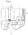
- FIG. 2 shows the bag closing machine of FIG. 1 with the die 9 advanced in the closing position.
- the die 9 With the power drive for the punch 3, the die 9 is brought into the closing position at a right angle and in a straight line via a linkage 11, 12.
- the tapered part 13 of the die 9 is then supported behind the clamp guide track 2 on a support 14.
- the stamp 3 has bent the clamp 4 around the bag braid 5 and closed it.
- the die 9 Simultaneously with the return stroke of the stamp 3 from the closing position, the die 9 is also returned in a straight line to its starting position (FIG. 1), so that the closed bag braid 5 can be removed against the feed direction.
- Fig. 3 shows a section of a bag closing machine, in which the die is pushed back against a spring force.
- the summarized end region 5 of the packaging envelope has the laterally displaceable when it is fed into the open receiving space 7 Die 9 pressed back against the restoring force of the spring 16 via a slope 15.
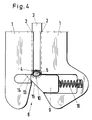
- FIG. 4 shows the bag closing machine of FIG. 3 in the closing position.
- the power drive need not operate the die 9.
- the closed bag braid 5 can be removed downwards.
Landscapes
- Engineering & Computer Science (AREA)
- Mechanical Engineering (AREA)
- Package Closures (AREA)
- Supplying Of Containers To The Packaging Station (AREA)
- Supply Of Fluid Materials To The Packaging Location (AREA)
- Bag Frames (AREA)
Description
Die Erfindung bezieht sich auf Verfahren und Vorrichtungen zum Verschließen von Verpackungshüllen aus biegsamem Material, insbesondere schlauchartigen Beuteln, mit einer U-förmigen Verschlußklammer nach dem Oberbegriff des Patentanspruchs 1.The invention relates to methods and devices for closing packaging sleeves made of flexible material, in particular tubular bags, with a U-shaped closure clip according to the preamble of
Es sind derartige Vorrichtungen, z.B. DE-A-15 11 725 und DE-A-12 84 350 bekannt, bei denen der zusammengefasste Endbereich der Verpackungshülle seitlich in den Aufnahmeraum zwischen den Führungsbahnen für die beiden Schenkel der Verschlußklammer eingeführt wird und bei denen die Matrize bereits ortsfest am Ende der Klammerführungsbahn in der Verschließposition angebracht ist. Die Vorrichtung gemäß DE-A-15 11 725 kann sowohl vertikal wie auch horizontal, z.B. zum Verschließen von senkrecht hängenden gefüllten Beuteln, verwendet werden. Nach dem Verschließen von senkrecht hängenden gefüllten Beuteln müssen diese aber zum Entfernen aus der Verschließmaschine zweckmäßigerweise nach unten abgezogen werden, weil ein Herausnehmen über die Zuführungsöffnung Schwierigkeiten macht. Die seitliche Zuführungsöffnung muß nämlich verhältnismäßig schmal gehalten werden, weil sonst die Klammerführungsbahn für einen der Schenkel der Verschlußklammer zu lange unterbrochen wird und dadurch ein Kippen der Verschlußklammer eintreten kann. Bei einer solch verhältnismäßig schmalen Einführung macht das Entfernen des verschlossenen Beutels entgegen der Zuführrichtung daher besondere Schwierigkeiten. Ein Entfernen des gefüllten und verschlossenen Beutels nach unten ist aber umständlich handhabbar.Such devices, e.g. DE-A-15 11 725 and DE-A-12 84 350 are known, in which the combined end region of the packaging envelope is inserted laterally into the receiving space between the guideways for the two legs of the closure clip and in which the die is already stationary at the end of the clip guideway is attached in the closed position. The device according to DE-A-15 11 725 can be used both vertically and horizontally, e.g. for the sealing of vertically hanging filled bags. After the closing of vertically hanging filled bags, however, these must expediently be pulled downwards to remove them from the sealing machine, because removal via the feed opening creates difficulties. The lateral feed opening must namely be kept relatively narrow, because otherwise the clip guide path is interrupted for too long for one of the legs of the locking clip and this can cause the locking clip to tilt. With such a relatively narrow insertion, the removal of the sealed bag against the feed direction therefore poses particular difficulties. Removing the filled and closed bag downwards is cumbersome to handle.
Es ist außerdem bekannt (DE-A-20 45 229), die Matrize in der Weise seitlich vor die Klammerführungsbahn zu führen, daß sie gleichzeitig mit den Raffarmen eingeschwenkt wird. In diesem Falle werden allerdings die Raffarme mit der Matrize gegen die straff gefüllte Verpackung geführt, so daß die vorstehend angesprochene Schwierigkeit nicht in Erscheinung treten kann.It is also known (DE-A-20 45 229) to guide the die laterally in front of the clamp guideway in such a way that it is pivoted in simultaneously with the shirring arms. In this case, however, the shirring arms are guided with the die against the tightly filled packaging, so that the above-mentioned difficulty cannot appear.
Schließlich ist es bekannt (DE-A-21 61 593), einen zu verschließenden Endbereich einer Verpackungshülle, der lose in eine gabelförmige Aufnahme gelegt ist, derart zu verschließen, daß er von dem sich darüber senkenden Klammerführungskanal einer Verpackungsmaschine erfaßt wird. Danach wird die Matrize an einem Hebel vor die Klammerführungsbahn geschwenkt, worauf der Stempel die Verschlußklammer auf der Matrize um den Verpackungszopf verschließt. Dabei wirken ganz erhebliche Verschließkräfte (ca. 300 kp) über die Matrize auf das Schwenk- und Arretierungssystem ein, was einen erheblichen Verschleiß und sich daraus ergebende Ungenauigkeiten zur Folge hat.Finally, it is known (DE-A-21 61 593) to close an end region of a packaging wrapper to be closed, which is placed loosely in a fork-shaped receptacle, in such a way that it is gripped by the clamp guiding channel of a packaging machine that sinks above it. The die is then pivoted on a lever in front of the clip guideway, whereupon the stamp closes the closure clip on the die around the packaging braid. Very considerable closing forces (approx. 300 kp) act on the swivel and locking system via the die, which results in considerable wear and the resulting inaccuracies.
Der Erfindung liegt daher die Aufgrunde zugrunde, Verfahren und Vorrichtungen der eingangs beschriebenen Art so auszugestalten, daß die beim Verschließvorgang auf die Matrize einwirkenden Kräfte nicht auf die Antriebsmechanik für die Matrize, sondern direkt auf den Grundkörper der Maschine übertragen werden.The invention is therefore based on the principles of designing methods and devices of the type described in the introduction in such a way that the forces acting on the die during the closing operation are not transmitted to the drive mechanism for the die, but rather directly to the base body of the machine.
Diese Aufgabe wird bei einem Verfahren nach dem Oberbegriff des Patentanspruchs 1 durch die im Kennzeichen des Patentanspruchs 1 angegebenen Maßnahmen gelöst.This object is achieved in a method according to the preamble of
Die Vorrichtung zur Ausführung dieses Verfahrens verfügt über die im Anspruch 3 angegebenen Merkmale.The device for performing this method has the features specified in
Das erfindungsgemäße Verfahren und die entsprechende Vorrichtung haben den Vorteil, daß der am oberen Ende mit einer Hand erfaßte gefüllte Beutel gradlinig in den offenen Aufnahmeraum eingeführt und nach dem Verschließen ohne Umgreifen oder zusätzliche Handgriffe aus der Verschließvorrichtung gradlinig in entgegengesetzter Richtung entnommen und abgelegt werden kann. Besonders vorteilhaft ist dies beim Verschließen von Beuteln, die mit dünnflüssigem Inhalt gefüllt und daher besonders schwierig handhabbar sind.The method according to the invention and the corresponding device have the advantage that the filled bag, gripped at the upper end with one hand, can be inserted straight into the open receiving space and, after being closed, removed and put down straight away from the closing device in the opposite direction without having to reach around or additional handles. This is particularly advantageous when closing bags which are filled with a low-viscosity content and are therefore particularly difficult to handle.
Ein weiterer Vorteil der Erfindung liegt darin, daß die Führungsnut für die Matrize die Verschließkräfte aufnimmt und damit die Gefahr vermieden wird, daß der Bewegungsmechanismus überbeansprucht wird. Außerdem kann die Matrize sich in der Verschließstellung beim Verschließvorgang selbst justieren, was bei einer eingeschwenkten Matrize nicht möglich ist.Another advantage of the invention is that the guide groove for the die absorbs the closing forces and thus the risk that the movement mechanism is overstressed is avoided. In addition, the die can adjust itself in the closed position during the closing process, which is not possible with a swung-in die.
Das erfindungsgemäße Verfahren wird zweckmäßigerweise durch einen Kraftantrieb ausgeführt, der in der Vorrichtung Stempel- und Matrizenhub in der erforderlichen Reihenfolge durchführt. Der Kraftantrieb kann ein Handhebel- oder ein druckbeaufschlagtes System sein.The method according to the invention is expediently carried out by a power drive which carries out the punch and die stroke in the required sequence in the device. The power drive can be a hand lever or a pressurized system.
Eine Abänderung des erfindungsgemäßen Verfahrens ist durch die Merkmale des Patentanspruchs 2 gekennzeichnet. Die entsprechende Vorrichtung besteht an Stelle der seitlich zum Ende der Klammerführungsbahnen verschiebbar angeordneten Matrize, aus einer bereits am Ende in der Verschließposition angeordneten Matrize, die bei der Zuführung des zusammengefaßten Endbereichs der zu verschließendn Verpackungshülle in den offenen Aufnahmeraum gegen eine Rückstellkraft aus der Verschließposition seitlich ausweicht. Bei dieser Ausführungsform wird das zusammengefaßte Ende der Verpackungshülle gegen eine Schräge der Matrize eingeführt, wodurch die Matrize gegen die Rückstellkraft seitlich ausweicht und anschließend wieder in die Verschließposition zurückgeht. Diese Ausführungsform hat ebenfalls den Vorteil, daß sie die gradlinige Zuführung des zusammengefaßten Endes der zu verschließenden Verpackungshülle ermöglicht.A modification of the method according to the invention is characterized by the features of
Nachfolgend wird ein ausgewähltes Ausführungsbeispiel der Erfindung anhand der nachstehenden Zeichnungen erläutert.A selected exemplary embodiment of the invention is explained below with reference to the drawings below.
Fig. 1 zeigt einen Ausschnitt einer Beutelverschließmaschine mit der Matrize in der Ausgangsposition.Fig. 1 shows a section of a bag closing machine with the die in the starting position.
Die Grundplatte 1 besitzt eine Klammerführungsbahn 2 zur Aufnahme des Stempels 3 und der U-förmigen Verschlußklammer 4. Zum gradlinigen Einführen des zusammengefaßten Endbereichs 5 der Verpackungshülle ist eine konische Öffnung 6 vorgesehen, die in einen offenen Aufnahmeraum 7 übergeht, in den der Endbereich 5 der Verpackungshülle vor dem Verschließen eingebracht wird.The
In einer Nut 8 rechtwinklig zur Klammerführungsbahn 2 befindet sich eine verschiebbare Matrize 9 mit ihrer Verschließkurve 10 in ihrer Ausgangsposition seitlich zum Ende der Klammerführungsbahn 2. Ein Gestänge 11,12 ist mit dem nicht gezeigten Kraftantrieb des Stempels 3 so verbunden, daß die Matrize dem Stempelhub voreilt.In a
Fig. 2 zeigt die Beutelverschließmaschine der Fig. 1 mit vorgeschobener Matrize 9 in der Verschließposition. Mit dem Kraftantrieb für den Stempel 3 ist über ein Gestänge 11,12 die Matrize 9 voreilend rechtwinklig und gradlinig in die Verschließposition verbracht. Der verjüngte Teil 13 der Matrize 9 stützt sich dann hinter der Klammerführungsbahn 2 auf einer Auflage 14 ab. Der Stempel 3 hat die Klammer 4 um den Beutelzopf 5 gebogen und verschlossen. Gleichzeitig mit dem Rückhub des Stempels 3 aus der Verschließposition wird die Matrize 9 ebenfalls gradlinig in ihre Ausgangsposition (Fig. 1) zurückgebracht, so daß der verschlossene Beutelzopf 5 entgegen der Zuführrichtung entnommen werden kann.FIG. 2 shows the bag closing machine of FIG. 1 with the die 9 advanced in the closing position. With the power drive for the
Fig. 3 zeigt einen Ausschnitt einer Beutelverschließmaschine, bei der die Matrize gegen eine Federkraft zurückgeschoben wird.Fig. 3 shows a section of a bag closing machine, in which the die is pushed back against a spring force.
Bei dieser Ausführungsform der Erfindung hat der zusammengefaßte Endbereich 5 der Verpackungshülle beim Zuführen in den offenen Aufnahmeraum 7 zunächst die seitlich verschiebbare Matrize 9 über eine Schräge 15 gegen die Rückstellkraft der Feder 16 zurückgedrückt.In this embodiment of the invention, the summarized
Fig. 4 zeigt die Beutelverschließmaschine der Fig. 3 in der Verschließposition.FIG. 4 shows the bag closing machine of FIG. 3 in the closing position.
Nachdem das zusammengefaßte Ende 5 des Beutels die Schräge 15 der Matrize 9 passiert hat, springt sie durch die Rückstellkraft der Feder 16 in ihre Verschließposition. Das verjüngte Teil 13 der Matrize 9 stützt sich dabei auf der Auflage 14 ab. Bei dieser Ausführungsform braucht der Kraftantrieb nicht die Matrize 9 zu betätigen.After the combined
Nachdem der Stempel 3 sich aus seiner Verschließpositon entfernt hat, kann der verschlossene Beutelzopf 5 nach unten entnommen werden.After the
Claims (5)
- A process for sealing packaging encasing made from pliable material, e.g., tube-like bags, having a U-shaped sealing clamp, whereby the to-be-sealed held together end area (5) of the packaging encasing is received in an opposite direction to the sealing direction, into a receiving area (7) which is open from below, arranged between the guide tracks (2) for the two flanks of the sealing clamp and for a sealing ram (3), and is sealed by same through a matrix (9) arranged laterally to the end of the clamp guide (2), which is brought into the sealing position at right angles to the end of the clamp guide track and leading the sealing clamp ram characterised in that the matrix is arranged displaceably in a guide groove (8), and is rectilinearly brought into the sealing position in the guide groove in such a manner that a narrow leading part of the matrix is supported by a rest (14) behind the clamp guide track.
- A process according to Claim 1 characterised in that on the insertion of the held together end area of the to-be-sealed packaging encasing, the matrix which is found in the sealing position, withdraws laterally against a restoring force, and after the insertion of the held together end area into the open receiving area, is returned to the sealing position.
- A device for carrying out the process according to any of Claims 1 or 2, and characterised by having a base plate (1) in which are located the guide tracks (2) for the two flanks of the sealing clamp (4) and the ram (3), and whereby an open receiving area (7) is formed between the guide tracks (2) of both flanks of the sealing clamp (4), for conveying the held together end area of the to-be-sealed packaging encasing, a matrix (9) which is arranged in a guide groove (8) which extends laterally to the end of the sealing clamp track (2), and a drive (11, 12, 16) for the matrix (9), which brings same into the sealing position in the guide groove (8) before the ram (3), together with the sealing clamp (4), has reached same, whereby the matrix (9) has a narrow leading part (13) which is supported on a rest (14) behind the clamp guide track (2).
- A device according to Claim 3, characterised by a common drive (11, 12) for the ram (3) and the matrix (9).
- A device according to Claim 3, characterised by a drive (16) whereby the matrix (9), thanks to a slope (15) attached to the matrix, flexibly withdraws laterally out of the sealing position against a restoring force, on conveying the held together end area (5) of the to-be-sealed packaging encasing into the receiving area (7).
Applications Claiming Priority (2)
| Application Number | Priority Date | Filing Date | Title |
|---|---|---|---|
| DE3931465 | 1989-09-21 | ||
| DE3931465 | 1989-09-21 |
Publications (2)
| Publication Number | Publication Date |
|---|---|
| EP0418944A1 EP0418944A1 (en) | 1991-03-27 |
| EP0418944B1 true EP0418944B1 (en) | 1993-03-31 |
Family
ID=6389855
Family Applications (1)
| Application Number | Title | Priority Date | Filing Date |
|---|---|---|---|
| EP90202248A Expired - Lifetime EP0418944B1 (en) | 1989-09-21 | 1990-08-21 | Method and apparatus for closing packing wraps of flexible material |
Country Status (4)
| Country | Link |
|---|---|
| US (1) | US5136824A (en) |
| EP (1) | EP0418944B1 (en) |
| DE (1) | DE59001115D1 (en) |
| ES (1) | ES2041497T3 (en) |
Families Citing this family (3)
| Publication number | Priority date | Publication date | Assignee | Title |
|---|---|---|---|---|
| US5445275A (en) * | 1994-06-08 | 1995-08-29 | Lazy Pet Products, Inc. | Full recovery reduced-volume packaging system |
| DE19901220B4 (en) * | 1999-01-14 | 2004-04-08 | Poly-Clip System Gmbh & Co Kg | Method and device for closing packages of flexible material |
| DE102005029227B4 (en) * | 2005-06-23 | 2007-11-08 | Poly-Clip System Gmbh & Co. Kg | clipping machine |
Family Cites Families (16)
| Publication number | Priority date | Publication date | Assignee | Title |
|---|---|---|---|---|
| CH371703A (en) * | 1958-12-27 | 1963-08-31 | Tipper Tie Products Inc | Sausage binding machine |
| US3293736A (en) * | 1965-06-28 | 1966-12-27 | Rheem Mfg Co | Clipping apparatus for applying a clip around a bag end including gate means for positioning the bag end |
| DE1284350B (en) * | 1966-03-23 | 1968-11-28 | Herbert Dipl Ing | Device for closing packaging made of flexible material by means of U-shaped locking clips |
| US3727288A (en) * | 1970-02-09 | 1973-04-17 | Grace W R & Co | Clipping system |
| DE2045229C3 (en) * | 1970-09-12 | 1979-01-11 | Herbert Dipl.-Ing. 6240 Koenigstein Niedecker | Device for closing packages |
| US3693314A (en) * | 1970-12-14 | 1972-09-26 | Grace W R & Co | Closing system for bags and the like |
| BR7108034D0 (en) * | 1970-12-14 | 1973-04-05 | Grace W R & Co | EVACUATION AND CLOSING SYSTEM |
| US3783583A (en) * | 1972-09-22 | 1974-01-08 | Rheem Mfg Co | Gathering means for clippers |
| US3914980A (en) * | 1973-01-10 | 1975-10-28 | Herbert Niedecker | Plier-like device for closing of packing wrappers |
| ES209592Y (en) * | 1975-01-24 | 1976-09-01 | Lorenzo Barroso | A STAPLER. |
| US4004339A (en) * | 1975-04-07 | 1977-01-25 | Rheem Manufacturing Company | Single piston operated clip device |
| GB1496740A (en) * | 1975-06-30 | 1977-12-30 | Grace W R & Co | Gathering and clipping head for vacuum packaging machines |
| DE2647598C3 (en) * | 1976-10-21 | 1982-04-15 | Technopack Ewald Hagedorn Kg, 2000 Hamburg | Device for closing a sack-like cover with a clip |
| DE2700641C3 (en) * | 1977-01-08 | 1979-09-20 | Herbert Dipl.-Ing. 6240 Koenigstein Niedecker | Packaging wrapper section having a hanger baptism and method and apparatus for attaching the same |
| US4458402A (en) * | 1983-01-03 | 1984-07-10 | Tipper Tie, Inc. | Adjustable crimping die for clipper mechanism |
| US4642865A (en) * | 1984-09-17 | 1987-02-17 | Howard Kelem | Method and apparatus for automatic pressure packing of a food casing |
-
1990
- 1990-08-21 EP EP90202248A patent/EP0418944B1/en not_active Expired - Lifetime
- 1990-08-21 ES ES199090202248T patent/ES2041497T3/en not_active Expired - Lifetime
- 1990-08-21 DE DE9090202248T patent/DE59001115D1/en not_active Expired - Fee Related
- 1990-09-18 US US07/584,316 patent/US5136824A/en not_active Expired - Lifetime
Also Published As
| Publication number | Publication date |
|---|---|
| EP0418944A1 (en) | 1991-03-27 |
| DE59001115D1 (en) | 1993-05-06 |
| US5136824A (en) | 1992-08-11 |
| ES2041497T3 (en) | 1993-11-16 |
Similar Documents
| Publication | Publication Date | Title |
|---|---|---|
| EP0135238B1 (en) | Device for closing tubelike package envelopes with u formed staples | |
| DE1782885B1 (en) | Device for placing the slider and the upper end links on ready-made coupled zippers | |
| DE1465242B2 (en) | Machine for pressing electrical connection terminals on a wire and for attaching a housing body to the pressed-on terminal | |
| DE1615684B1 (en) | Feed and cutting device for a machine for the simultaneous attachment of several electrical connectors | |
| DE2927235A1 (en) | DEVICE FOR INSULATING THE ELECTRICAL LADDERS | |
| DE2647598C3 (en) | Device for closing a sack-like cover with a clip | |
| EP0418944B1 (en) | Method and apparatus for closing packing wraps of flexible material | |
| DE60308594T2 (en) | Method and device for venting a bag filling machine | |
| DE3206675A1 (en) | Device for filling and closing sausage casings | |
| DE8311424U1 (en) | DEVICE FOR INSERTING PINS WITH SQUARE CROSS-SECTION INTO THE PCB OF A PRINTED CIRCUIT | |
| DE19825106C1 (en) | Device for marking closure clips | |
| DE2711430C3 (en) | Closing and cutting device for gathered packaging tubes, such as sausage casings, bags and the like | |
| DE1615052A1 (en) | Machine for making wire connections | |
| DE102004022716B4 (en) | Device for producing filled, sealed tubular bag packages | |
| DE3911870C2 (en) | ||
| DE4334930C1 (en) | Assembly tool for placing a marking element on a strand-shaped material | |
| DE2558793C2 (en) | Device for closing bags or the like by means of a wire clip | |
| DE19850544A1 (en) | Filling and closing station for compressible objects to be put in bags, with bag holder, bag opener pusher, closing device and suction jaws on holder | |
| DE2154894A1 (en) | Closing device for bags | |
| DE1465242C (en) | Machine for pressing electrical connection terminals onto a wire and attaching a housing body to the pressed-on terminal | |
| EP0487491B1 (en) | Intermediate member piece | |
| DE1511754A1 (en) | Bracket fastening device | |
| DE2300993B1 (en) | Tong-like device for closing packaging sleeves | |
| DE1511725C3 (en) | Device for closing packages made of flexible material | |
| DE2156019C3 (en) | Device for filling a packaging insert |
Legal Events
| Date | Code | Title | Description |
|---|---|---|---|
| PUAI | Public reference made under article 153(3) epc to a published international application that has entered the european phase |
Free format text: ORIGINAL CODE: 0009012 |
|
| AK | Designated contracting states |
Kind code of ref document: A1 Designated state(s): DE ES FR GB IT NL |
|
| 17P | Request for examination filed |
Effective date: 19910430 |
|
| 17Q | First examination report despatched |
Effective date: 19920702 |
|
| GRAA | (expected) grant |
Free format text: ORIGINAL CODE: 0009210 |
|
| AK | Designated contracting states |
Kind code of ref document: B1 Designated state(s): DE ES FR GB IT NL |
|
| REF | Corresponds to: |
Ref document number: 59001115 Country of ref document: DE Date of ref document: 19930506 |
|
| ITF | It: translation for a ep patent filed |
Owner name: STUDIO BREVETTI JAUMANN |
|
| ET | Fr: translation filed | ||
| REG | Reference to a national code |
Ref country code: ES Ref legal event code: FG2A Ref document number: 2041497 Country of ref document: ES Kind code of ref document: T3 |
|
| PLBE | No opposition filed within time limit |
Free format text: ORIGINAL CODE: 0009261 |
|
| STAA | Information on the status of an ep patent application or granted ep patent |
Free format text: STATUS: NO OPPOSITION FILED WITHIN TIME LIMIT |
|
| GBT | Gb: translation of ep patent filed (gb section 77(6)(a)/1977) |
Effective date: 19940207 |
|
| 26N | No opposition filed | ||
| PGFP | Annual fee paid to national office [announced via postgrant information from national office to epo] |
Ref country code: GB Payment date: 19950731 Year of fee payment: 6 |
|
| PGFP | Annual fee paid to national office [announced via postgrant information from national office to epo] |
Ref country code: FR Payment date: 19950817 Year of fee payment: 6 |
|
| PGFP | Annual fee paid to national office [announced via postgrant information from national office to epo] |
Ref country code: NL Payment date: 19950822 Year of fee payment: 6 |
|
| PGFP | Annual fee paid to national office [announced via postgrant information from national office to epo] |
Ref country code: ES Payment date: 19950829 Year of fee payment: 6 |
|
| PG25 | Lapsed in a contracting state [announced via postgrant information from national office to epo] |
Ref country code: GB Effective date: 19960821 |
|
| PG25 | Lapsed in a contracting state [announced via postgrant information from national office to epo] |
Ref country code: ES Free format text: LAPSE BECAUSE OF THE APPLICANT RENOUNCES Effective date: 19960822 |
|
| PG25 | Lapsed in a contracting state [announced via postgrant information from national office to epo] |
Ref country code: NL Effective date: 19970301 |
|
| GBPC | Gb: european patent ceased through non-payment of renewal fee |
Effective date: 19960821 |
|
| PG25 | Lapsed in a contracting state [announced via postgrant information from national office to epo] |
Ref country code: FR Effective date: 19970430 |
|
| NLV4 | Nl: lapsed or anulled due to non-payment of the annual fee |
Effective date: 19970301 |
|
| REG | Reference to a national code |
Ref country code: FR Ref legal event code: ST |
|
| REG | Reference to a national code |
Ref country code: ES Ref legal event code: FD2A Effective date: 19991007 |
|
| PGFP | Annual fee paid to national office [announced via postgrant information from national office to epo] |
Ref country code: DE Payment date: 20030924 Year of fee payment: 14 |
|
| PG25 | Lapsed in a contracting state [announced via postgrant information from national office to epo] |
Ref country code: DE Free format text: LAPSE BECAUSE OF NON-PAYMENT OF DUE FEES Effective date: 20050301 |
|
| PG25 | Lapsed in a contracting state [announced via postgrant information from national office to epo] |
Ref country code: IT Free format text: LAPSE BECAUSE OF NON-PAYMENT OF DUE FEES;WARNING: LAPSES OF ITALIAN PATENTS WITH EFFECTIVE DATE BEFORE 2007 MAY HAVE OCCURRED AT ANY TIME BEFORE 2007. THE CORRECT EFFECTIVE DATE MAY BE DIFFERENT FROM THE ONE RECORDED. Effective date: 20050821 |