EP0418205A2 - Radar arrangement - Google Patents
Radar arrangement Download PDFInfo
- Publication number
- EP0418205A2 EP0418205A2 EP90850285A EP90850285A EP0418205A2 EP 0418205 A2 EP0418205 A2 EP 0418205A2 EP 90850285 A EP90850285 A EP 90850285A EP 90850285 A EP90850285 A EP 90850285A EP 0418205 A2 EP0418205 A2 EP 0418205A2
- Authority
- EP
- European Patent Office
- Prior art keywords
- frequency
- code
- radar
- signal
- receiver
- Prior art date
- Legal status (The legal status is an assumption and is not a legal conclusion. Google has not performed a legal analysis and makes no representation as to the accuracy of the status listed.)
- Withdrawn
Links
- 230000004044 response Effects 0.000 claims abstract description 7
- 230000000875 corresponding effect Effects 0.000 claims description 14
- 238000012545 processing Methods 0.000 claims description 13
- 238000002592 echocardiography Methods 0.000 claims description 10
- 238000000034 method Methods 0.000 claims description 7
- 238000001514 detection method Methods 0.000 claims description 5
- 230000000694 effects Effects 0.000 claims description 5
- 230000005540 biological transmission Effects 0.000 claims description 4
- 230000002596 correlated effect Effects 0.000 claims description 4
- 238000006073 displacement reaction Methods 0.000 claims description 4
- 230000008878 coupling Effects 0.000 claims description 3
- 238000010168 coupling process Methods 0.000 claims description 3
- 238000005859 coupling reaction Methods 0.000 claims description 3
- 230000001360 synchronised effect Effects 0.000 claims description 3
- 230000002238 attenuated effect Effects 0.000 claims description 2
- 238000006243 chemical reaction Methods 0.000 claims description 2
- 230000000295 complement effect Effects 0.000 claims description 2
- 238000012937 correction Methods 0.000 claims description 2
- 230000008569 process Effects 0.000 claims description 2
- 230000000750 progressive effect Effects 0.000 claims 1
- 238000004891 communication Methods 0.000 description 8
- 238000010276 construction Methods 0.000 description 3
- 239000000543 intermediate Substances 0.000 description 3
- 230000010363 phase shift Effects 0.000 description 2
- 230000035945 sensitivity Effects 0.000 description 2
- 238000004458 analytical method Methods 0.000 description 1
- 230000008901 benefit Effects 0.000 description 1
- 230000001427 coherent effect Effects 0.000 description 1
- 229940000425 combination drug Drugs 0.000 description 1
- 230000006835 compression Effects 0.000 description 1
- 238000007906 compression Methods 0.000 description 1
- 238000013461 design Methods 0.000 description 1
- 238000010586 diagram Methods 0.000 description 1
- 238000005516 engineering process Methods 0.000 description 1
- 238000001914 filtration Methods 0.000 description 1
- 238000003199 nucleic acid amplification method Methods 0.000 description 1
- 230000002688 persistence Effects 0.000 description 1
- 230000001681 protective effect Effects 0.000 description 1
- 238000010079 rubber tapping Methods 0.000 description 1
- 238000005070 sampling Methods 0.000 description 1
Images
Classifications
-
- G—PHYSICS
- G01—MEASURING; TESTING
- G01S—RADIO DIRECTION-FINDING; RADIO NAVIGATION; DETERMINING DISTANCE OR VELOCITY BY USE OF RADIO WAVES; LOCATING OR PRESENCE-DETECTING BY USE OF THE REFLECTION OR RERADIATION OF RADIO WAVES; ANALOGOUS ARRANGEMENTS USING OTHER WAVES
- G01S7/00—Details of systems according to groups G01S13/00, G01S15/00, G01S17/00
- G01S7/02—Details of systems according to groups G01S13/00, G01S15/00, G01S17/00 of systems according to group G01S13/00
-
- G—PHYSICS
- G01—MEASURING; TESTING
- G01S—RADIO DIRECTION-FINDING; RADIO NAVIGATION; DETERMINING DISTANCE OR VELOCITY BY USE OF RADIO WAVES; LOCATING OR PRESENCE-DETECTING BY USE OF THE REFLECTION OR RERADIATION OF RADIO WAVES; ANALOGOUS ARRANGEMENTS USING OTHER WAVES
- G01S13/00—Systems using the reflection or reradiation of radio waves, e.g. radar systems; Analogous systems using reflection or reradiation of waves whose nature or wavelength is irrelevant or unspecified
- G01S13/02—Systems using reflection of radio waves, e.g. primary radar systems; Analogous systems
- G01S13/06—Systems determining position data of a target
- G01S13/08—Systems for measuring distance only
- G01S13/10—Systems for measuring distance only using transmission of interrupted, pulse modulated waves
- G01S13/24—Systems for measuring distance only using transmission of interrupted, pulse modulated waves using frequency agility of carrier wave
-
- G—PHYSICS
- G01—MEASURING; TESTING
- G01S—RADIO DIRECTION-FINDING; RADIO NAVIGATION; DETERMINING DISTANCE OR VELOCITY BY USE OF RADIO WAVES; LOCATING OR PRESENCE-DETECTING BY USE OF THE REFLECTION OR RERADIATION OF RADIO WAVES; ANALOGOUS ARRANGEMENTS USING OTHER WAVES
- G01S13/00—Systems using the reflection or reradiation of radio waves, e.g. radar systems; Analogous systems using reflection or reradiation of waves whose nature or wavelength is irrelevant or unspecified
- G01S13/02—Systems using reflection of radio waves, e.g. primary radar systems; Analogous systems
- G01S13/06—Systems determining position data of a target
- G01S13/08—Systems for measuring distance only
- G01S13/32—Systems for measuring distance only using transmission of continuous waves, whether amplitude-, frequency-, or phase-modulated, or unmodulated
- G01S13/325—Systems for measuring distance only using transmission of continuous waves, whether amplitude-, frequency-, or phase-modulated, or unmodulated using transmission of coded signals, e.g. P.S.K. signals
Definitions
- the present invention relates to a radar arrangement of the type comprising a transmitter which essentially continuously transmits a modulated carrier wave signal and a receiver for receiving the carrier wave signal reflected at an object (echo signal).
- Radar can be considered as a device for measuring and communication.
- the radar sends out a pulse and measures the time for the echo from the reflecting object to reach the radar receiver. Echoes from different objects can have different appearances - for example, moving objects give a Doppler shift of frequency - and by analyzing the echoes, certain information about the reflecting object can be obtained. If the echo analysis can be said to constitute the measuring function of the radar, then the transmission of the pulse itself to the reflecting object and the transmission of the echo response back to the radar can be said to constitute the communication part of the radar.
- the radar's communication function is sensitive to interference and limited in range by wave propagation characteristics such as atmospheric attenuation, curvature of the earth and so forth.
- the communication characteristics of the radar are particularly significant in military applications. Countermeasures which can prevent radar functioning are constantly being developed and the communication characteristics of the radar are critical with regard to how vulnerable the radar is to different countermeasure systems.
- the radar can be disturbed actively or passively.
- active interference power is generated within the frequency range of the radar and is transmitted towards the radar which thereby experiences false echoes - often of such an amplitude and persistence that the receiver function is completely blanked out within certain parts of the radar coverage area.
- Passive interference involves creating decoys, for example by creating "clouds" of reflecting strips. The echoes from the strips can be so great that echoes from aeroplanes and boats do not stand out within the strip area.
- signal interception devices are used. These are found in many versions, from simple warning receivers to highly advanced interception equipment with advanced analyzing functions.
- the signal interception equipment is designed for detecting radar pulses by a wide-band method which provides poor receiver sensitivity compared with a radar receiver.
- the radar loses more signal power due to the fact that the signal must go out and back to reach the radar receiver but only go one way to reach the signal interception equipment. This relation has the result that the signal interception equipment can detect the radar at a longer range than the radar can seen the actual target.
- the signal interception equipment is designed to sense the peak power, while the radar receiver senses the average power.
- CW radar continuous wave
- This radar has special characteristics, for example as warning radar for fast moving targets. If the radar transmits on one frequency, there must be a Doppler shift in the frequency of the echo signal for the received signal to be detected. This radar therefore does not provide any possibility for determining distance to the target.
- Other ideas for the CW radar have also been found.
- the radar is "quiet".
- FMCW radar frequency modulated continuous wave
- PILOT radar developed by Philips.
- the FMCW radar is difficult to spot and is "silent".
- the risk that this type of radar can also be disturbed is increased as a result of more sophisticated countermeasures.
- the frequency modulation of the FMCW radar can provide an error in range determination upon detection of moving targets.
- TWT travelling wave tube
- the radar transmitter comprises a magnetron tube which transmits short pulses of the order of magnitude of 0.05-5 ⁇ s with high power
- a travelling wave tube is utilized in TWT radar.
- Such a tube cannot provide peak powers of the same magnitude as a magnetron, which is why the pulse durations need to be increased in order to obtain corresponding avarage powers.
- the advantage with TWT radar is that it can provide good MTI characteristics.
- the disadvantage is the poor range resolution compared with conventional pulsed radar.
- TWT radar To increase the range resolution in TWT radar, it is already known to vary the frequency or phase in the transmitted pulse. This can be done by analog or digital means and provides a certain pulse compression which increases the range resolution of the radar.
- the TWT radar is also a pulsed radar which can be easily spotted by signal interception equipment.
- the object of the present invention is to produce a new type of radar which is difficult to spot by signal interception equipment and difficult to analyze and, moreover, difficult to disturb, with a design which provides good radar performance for MTI, range accuracy and so forth.
- a further object of the invention is to produce a radar in which the expensive high-power technology at the transmitter end has been reduced but which, nevertheless, has increased functionality compared with traditional radar.
- the invention is in principle a CW radar, which transmits and receives information at the same time and continuously in time, in contrast to a traditional pulse radar.
- the radar transmits long coded messages in contrast to traditional radar which transmit one bit in order of magnitude
- - the range resolution of the radar is determined by the code frequency of the message
- - the coded message of the radar is divided up into blocks, the RF frequency being changed between blocks
- - the code frequency is considerably higher than the corresponding block frequency
- the RF signal can be coded by means of frequency coding, phase coding, amplitude coding or a combination of several coding methods
- - the radar sends out a code block at a frequency which is different from the frequency or frequencies received by the radar
- - the radar stores the transmitted code message and correlates the incoming echo response with the stored message.
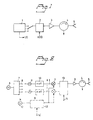
- Figure 1 shows the basic construction of the transmitter
- Figure 2 shows an example of how frequency generation and modulation are created in the transmitter
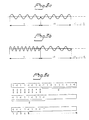
- Figure 3 shows an example of how the code-generating signal can look
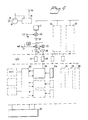
- Figure 4 shows in a block diagram form the basic construction of the receiver.
- the transmitter comprises a carrier wave generator 1 of the type which continuously transmits a carrier wave signal, the signal is supplied to a modulator 2 for modulation with a code-generating signal whose fundamental frequency, the code frequency, is determining for the range resolution of the radar.
- the transmitter also comprises a power amplifier 3 for the modulated carrier wave signal, circulator 4 and transmitter antenna 5.
- FIG. 2 shows in slightly more detail an example of how the frequency generation and modulation can be produced.
- the transmitter arrangement consists of a stable oscillator 6 whose oscillator signal is supplied to a frequency generator 7 whose output has a switch 8 for coupling-in of one or more phase-locked oscillators 9.
- the phase-locked frequency signal is supplied to a frequency multiplier 10.
- mixing takes place at 11 with an intermediate frequency generated in an intermediate-frequency oscillator 12.
- the transmitting frequency or transmitting frequencies generated are supplied to a code modulator 13 for code modulation with a code-generating signal 14.
- code modulation can be carried out at the intermediate frequency level, which is indicated in the figure by the code modulator 13′.
- the code-modulated carrier frequency signal is thereafter supplied in a manner known per se to the circulator and transmitting antenna of the transmitter.
- circuit for frequency generation and modulation described above constitutes only one example. Several alternative embodiments can occur within the context of the invention.
- the code-generating signal 14 is of such a nature that one bit in the code has a duration which is several times longer than the time of the period of the carrier wave signal and that a code with several bits forms a block, a block being characterized by modulation of a carrier wave with constant frequency.
- the carrier wave frequency is furthermore changed between blocks so that the transmitter transmits one block with a carrier wave frequency which is different from the carrier wave frequency or frequencies which the receiver is set up to receive.
- the block length can be made considerably shorter than the corresponding range of the radar, which means that the radar transmitter frequently changes frequency in the time it takes to obtain an echo response from the range limit, which increases robustness with respect to detection and interference.
- the coding is produced by either phase modulation, frequency modulation, amplitude modulation or a combination of these methods.
- the coding of the carrier frequency signal can be done by means of biphase coding as binary code, in which one of the two phases is allocated to each bit.
- the carrier frequency signal can be coded by means of frequency coding as binary code, in which one frequency of the two is allocated to each bit, or in which the power is such that the result can be considered as two amplitude-modulated codes each with its own frequency, in which the amplitude modulation is complementary so that, when the radar is transmitting one bit at one frequency, it is not transmitting on the second frequency.
- the coding of the carrier frequency can utilize more phase positions or more frequencies than in the case of the binary code and thus, above all, less errors are contributed to the correlation result in the receiver due to longer codes.
- Figure 3 shows an example of the appearance of a code-generating signal 14, in this case a biphase coding with a 180° phase shift (a) and a frequency coding (b).
- the code-generating signal can be generated in a manner known per se by known code sequences being stored or generated randomly or generated by means of given algorithms.
- FIG. 4 shows an example of the construction of the receiver.
- An echo from the transmitted modulated carrier wave signal is received by an antenna 15. Any interference signals are also received by the antenna. Via a circulator 16, the received signal reaches the receiver circuit itself which comprises a receiver protection 17 in the form of a limiter and possibly a filter which admits the intended receiver signal frequency band but blocks the signal frequency of the transmitter, among others.
- a receiver protection 17 in the form of a limiter and possibly a filter which admits the intended receiver signal frequency band but blocks the signal frequency of the transmitter, among others.
- canceller 18 can be introduced in the receiver chain. This can provide extra protection against incoming transmitter power in the receiver by tapping off power from the transmitter channel and adjusting the phase and amplitude of this part of the transmit signal and thereafter introducing it in opposite phase to the part of the transmitter signal which is leaking through the circulator 16 or is reflected after the circulator and in the vicinity of the antenna.
- the canceller 18 can also be designed to suppress interference which is received from the sidelobes of the antenna.
- a signal is derived from an extra antenna 19 and this signal is adjusted in phase and amplitude so that the interference coming in via the main antenna 15 is blanked out (for example suppressed).
- the LO signal 19 of the radar is mixed in a mixer 20 with the receiver signal frequency to form an intermediate frequency (IF).
- the signal is supplied to a filtering and amplifying circuit 21 and thereafter mixed in mixers 22 and 23 with an IF signal 24 supplied to form a video signal.
- the video signal is taken out as an I channel and a Q channel, 25 and 26, respectively, by rotating the IF signal 24 supplied by 90° before the one mixer 23.
- I and Q channels are required for retaining the phase information which, in turn, is required for synchronous detection and coherent MTI operation.
- Sampling and A/D conversion in the signal processing elements 27, 28, which may be located already at the IF level, are followed by digital signal processing.
- the requirement for dynamic range in the A/D converters and later signal processing elements can be limited by introducing controlled attenuation of the receiver signal (for example STC) in the receiver protection 17 and/or in the intermediate-amplification section.
- the received signal can be correlated with the code which has been stored in element 14a and is the same which the transmitter sent out earlier and which has reached the range zone of interest to the receiver and has now come back to the receiver.
- the correlator 29 can be constructed in different lengths to match current code lengths.
- the correlator can also be equipped with a correction function which uses the primary result of the correlation, and if this value is greater than a value given before, the error contribution of this value to the correlation results received earlier or later thereby is calculated and these values are adjusted correspondingly which involves a successive storage of the primary results of the correlation before the adjustments are clear and the adjusted, secondary correlation results are used for further signal processing.
- An analyzer 30 assembles the values from the different code blocks in a suitable manner on the basis of the actual Doppler characteristics of the target and so forth.
- the digital signal processing part is connected to control electronics 31, known per se, for power, display, communication, processes and so forth.
- HF units 32, 33 have also been marked by dashed lines which indicate the capability of the radar to receive radar echoes of more than one carrier frequency at the same time.
- These HF units can be coupled together to the same signal processing unit or switched to further signal processing units 34, 35, 36 marked by dashed lines in the figure to indicate the capability of the radar to analyze echoes from different range zones with different signal processing functions at the same time.
- the range information is obtained in the following way.
- the code sent out is stored in the receiver and correlated with the received signal.
- the contributions from the individual code bits are summed together.
- This position in time defines the range to the object which has reflected the corresponding coded carrier wave signal sent out from the transmitter, see Figure 3c.
- the figure shows the relationship when the a first bits of the transmitted and stored code have reached the receiver and been stepped on. With each stepping-on, the contents in compartment 1 are multiplied by each other, the contents in compartment 2 are multiplied by each other and so forth so that a number of products is formed in the product register.
- the receiver can be constructed to receive at the same time the signal from blocks at at least two different frequencies, and the signals are processed differently in the receiver by division in frequency.
- the block reflected from the near zone of the radar can be selectively attenuated in the receiver relative to the block which is reflected from the far zone of the radar in order to reduce in this way the requirement for dynamic range in the signal processing unit of the receiver.
- the receiver at the same time can receive the signal from blocks at at least two different frequencies implies, at the same time, that the receiver can dedicate certain analyzing functions to a certain range zone and partially other analyzing functions to another range zone by selecting corresponding blocks which have been reflected from the respective range zone and coupling them to respective analyzing functions in the receiver.
- one range zone can be analyzed with respect to Doppler effects of moving targets and a second range zone can be analyzed with respect to a good range resolution of the target.
- each frequency can be separately decoded in a first step.
- the amplitude code obtained in this manner is correlated with the stored code in the receiver.
- samples are obtained in the compartments when, according to the code, no power will be found as echo from an actual range.
- these samples are assembled, they provide a measure of the size of radar echoes which do not originate from the correct range and are thus not synchronous. If the radar is exposed to an interference, the samples of this interference can provide a measure of the actual interference power.
- the code is designed in such a way that over a given number of code bits, n, the number of bits of one binary frequency is equal to the number of bits of the second binary frequency, displacements of the code by one or more bits provide a small and known contribution to the correlation.
- a radar can dedicate different radar functions to different range zones.
- a radar has the same function over all of its range zone, which means that if top performance is required for one function in one zone and a second function in a second zone, all requirements are added up to contain at the same time all good characteristics over the entire coverage zone of the radar.
- the radar according to the present invention which transmits different blocks can dedicate the reception of different blocks to different receiver functions.
- a radar can be used in an application as follows.
- the near zone will have simple surveillance. In a medium zone, vehicles will be fought with a battery and the radar will have a high resolution and good fire control characteristics in this area. An outer zone will be especially monitored for fast low-flying aeroplanes or missiles.
- the radar can here dedicate a powerful high-resolution receiver function without MTI to the middle zone whilst the outer zone can have low range resolution with good MTI.
- the correlator is preferably constructed of several subunits, where the correlation results from a respective subunit are stored for more than one position in time so that the results from the different subunits can be assembled in different time sequences.
- a summation of the results of the subunits in a certain time sequence thereby corresponds to a phase shift of the moving target due to the Doppler effect in a corresponding speed interval.
Landscapes
- Engineering & Computer Science (AREA)
- Radar, Positioning & Navigation (AREA)
- Remote Sensing (AREA)
- Computer Networks & Wireless Communication (AREA)
- Physics & Mathematics (AREA)
- General Physics & Mathematics (AREA)
- Radar Systems Or Details Thereof (AREA)
Abstract
Description
- The present invention relates to a radar arrangement of the type comprising a transmitter which essentially continuously transmits a modulated carrier wave signal and a receiver for receiving the carrier wave signal reflected at an object (echo signal).
- Radar can be considered as a device for measuring and communication. In a traditional pulsed radar, the radar sends out a pulse and measures the time for the echo from the reflecting object to reach the radar receiver. Echoes from different objects can have different appearances - for example, moving objects give a Doppler shift of frequency - and by analyzing the echoes, certain information about the reflecting object can be obtained. If the echo analysis can be said to constitute the measuring function of the radar, then the transmission of the pulse itself to the reflecting object and the transmission of the echo response back to the radar can be said to constitute the communication part of the radar.
- In a way corresponding to radio communication, the radar's communication function is sensitive to interference and limited in range by wave propagation characteristics such as atmospheric attenuation, curvature of the earth and so forth.
- The communication characteristics of the radar are particularly significant in military applications. Countermeasures which can prevent radar functioning are constantly being developed and the communication characteristics of the radar are critical with regard to how vulnerable the radar is to different countermeasure systems.
- The radar can be disturbed actively or passively. In active interference, power is generated within the frequency range of the radar and is transmitted towards the radar which thereby experiences false echoes - often of such an amplitude and persistence that the receiver function is completely blanked out within certain parts of the radar coverage area. Passive interference involves creating decoys, for example by creating "clouds" of reflecting strips. The echoes from the strips can be so great that echoes from aeroplanes and boats do not stand out within the strip area.
- In both passive and active interference, the party producing the interference thereby exposes its presence and its need for protective activity. It is frequently an important part of strategy to expose as little as possible of one's activities to the enemy. This means using neither radar nor countermeasures against radar until this is tactically justified.
- To spot radar, signal interception devices are used. These are found in many versions, from simple warning receivers to highly advanced interception equipment with advanced analyzing functions.
- Most of the signal interception equipment is designed for detecting radar pulses by a wide-band method which provides poor receiver sensitivity compared with a radar receiver. However, the radar loses more signal power due to the fact that the signal must go out and back to reach the radar receiver but only go one way to reach the signal interception equipment. This relation has the result that the signal interception equipment can detect the radar at a longer range than the radar can seen the actual target.
- What has been said applies to traditional pulsed radars where the peak pulse power is much greater than the average power of the radar. The signal interception equipment is designed to sense the peak power, while the radar receiver senses the average power.
- It is already known to use continuous wave (CW) radar. This has special characteristics, for example as warning radar for fast moving targets. If the radar transmits on one frequency, there must be a Doppler shift in the frequency of the echo signal for the received signal to be detected. This radar therefore does not provide any possibility for determining distance to the target. Other ideas for the CW radar have also been found. Most of the attempts with CW radar, however, have not led to any success, which is why radar signal interception equipment is frequently not equipped to spot su<.h a radar. Moreover, for a CW radar it holds true that the peak power = average power, which has the result that the signal interception equipment with its poor sensitivity can have a shorter range than the corresponding own range of the CW radar. That is to say that the radar can operate without being spotted. The radar is "quiet".
- This is a very interesting characteristic of the radar since it must be known that there is a radar, the direction in which it is located and on what frequencies it transmits in order to be able to define a disturbance of the radar.
- It is already known to be able to obtain range information from CW radar, for example by coupling together two or more radars to obtain a calculated point for the echo by interception technique. Another way to obtain range information by means of one radar is to use so-called frequency modulated continuous wave (FMCW) radar where the frequency of the transmitted carrier wave is changed (increased) continuously with time. An example of this type of radar is the PILOT radar developed by Philips. Like conventional CW radar, the FMCW radar is difficult to spot and is "silent". However, the risk that this type of radar can also be disturbed is increased as a result of more sophisticated countermeasures. Besides, the frequency modulation of the FMCW radar can provide an error in range determination upon detection of moving targets.
- There is another type of radar on the market which should be mentioned in this connection, namely the so-called travelling wave tube (TWT) radar. Unlike a traditional pulsed radar, where the radar transmitter comprises a magnetron tube which transmits short pulses of the order of magnitude of 0.05-5 µs with high power, a travelling wave tube is utilized in TWT radar. Such a tube cannot provide peak powers of the same magnitude as a magnetron, which is why the pulse durations need to be increased in order to obtain corresponding avarage powers. The advantage with TWT radar is that it can provide good MTI characteristics. The disadvantage is the poor range resolution compared with conventional pulsed radar.
- To increase the range resolution in TWT radar, it is already known to vary the frequency or phase in the transmitted pulse. This can be done by analog or digital means and provides a certain pulse compression which increases the range resolution of the radar.
- The TWT radar is also a pulsed radar which can be easily spotted by signal interception equipment.
- The object of the present invention is to produce a new type of radar which is difficult to spot by signal interception equipment and difficult to analyze and, moreover, difficult to disturb, with a design which provides good radar performance for MTI, range accuracy and so forth.
- A further object of the invention is to produce a radar in which the expensive high-power technology at the transmitter end has been reduced but which, nevertheless, has increased functionality compared with traditional radar.
- The feature which may chiefly be considered to be new and characteristic of the invention is found in the characterizing part of
Claim 1. - By way of introduction, it emerges that the invention is in principle a CW radar, which transmits and receives information at the same time and continuously in time, in contrast to a traditional pulse radar.
- To obtain a good resistance to interference and reliability, coding of information is used in information transmission which provides redundancy both in time and frequency to produce a robust communication system.
- - According to the invention, the radar transmits long coded messages in contrast to traditional radar which transmit one bit in order of magnitude,
- the range resolution of the radar is determined by the code frequency of the message,
- the coded message of the radar is divided up into blocks, the RF frequency being changed between blocks,
- the code frequency is considerably higher than the corresponding block frequency and the RF signal can be coded by means of frequency coding, phase coding, amplitude coding or a combination of several coding methods,
- the radar sends out a code block at a frequency which is different from the frequency or frequencies received by the radar,
- the radar stores the transmitted code message and correlates the incoming echo response with the stored message. When code correspondence (synchronism) is obtained, this corresponds to a definitive position of the echo response reflector,
- by changing frequency between the blocks, different range zones can be treated in different ways, that is to say different "types of radar" can be dedicated to different range zones. - An embodiment of the invention is shown diagrammatically in the attached drawings, in which Figure 1 shows the basic construction of the transmitter, Figure 2 shows an example of how frequency generation and modulation are created in the transmitter, Figure 3 shows an example of how the code-generating signal can look and Figure 4 shows in a block diagram form the basic construction of the receiver.
- The transmitter comprises a
carrier wave generator 1 of the type which continuously transmits a carrier wave signal, the signal is supplied to amodulator 2 for modulation with a code-generating signal whose fundamental frequency, the code frequency, is determining for the range resolution of the radar. The transmitter also comprises apower amplifier 3 for the modulated carrier wave signal,circulator 4 andtransmitter antenna 5. - Figure 2 shows in slightly more detail an example of how the frequency generation and modulation can be produced. The transmitter arrangement consists of a
stable oscillator 6 whose oscillator signal is supplied to afrequency generator 7 whose output has aswitch 8 for coupling-in of one or more phase-lockedoscillators 9. The phase-locked frequency signal is supplied to afrequency multiplier 10. To obtain a suitable transmitting frequency, mixing takes place at 11 with an intermediate frequency generated in an intermediate-frequency oscillator 12. The transmitting frequency or transmitting frequencies generated are supplied to acode modulator 13 for code modulation with a code-generatingsignal 14. Alternatively, code modulation can be carried out at the intermediate frequency level, which is indicated in the figure by thecode modulator 13′. The code-modulated carrier frequency signal is thereafter supplied in a manner known per se to the circulator and transmitting antenna of the transmitter. - As mentioned above, the circuit for frequency generation and modulation described above constitutes only one example. Several alternative embodiments can occur within the context of the invention.
- The code-generating
signal 14 is of such a nature that one bit in the code has a duration which is several times longer than the time of the period of the carrier wave signal and that a code with several bits forms a block, a block being characterized by modulation of a carrier wave with constant frequency. - The carrier wave frequency is furthermore changed between blocks so that the transmitter transmits one block with a carrier wave frequency which is different from the carrier wave frequency or frequencies which the receiver is set up to receive.
- The block length can be made considerably shorter than the corresponding range of the radar, which means that the radar transmitter frequently changes frequency in the time it takes to obtain an echo response from the range limit, which increases robustness with respect to detection and interference.
- The coding is produced by either phase modulation, frequency modulation, amplitude modulation or a combination of these methods. For example, the coding of the carrier frequency signal can be done by means of biphase coding as binary code, in which one of the two phases is allocated to each bit.
- Alternatively, the carrier frequency signal can be coded by means of frequency coding as binary code, in which one frequency of the two is allocated to each bit, or in which the power is such that the result can be considered as two amplitude-modulated codes each with its own frequency, in which the amplitude modulation is complementary so that, when the radar is transmitting one bit at one frequency, it is not transmitting on the second frequency.
- The coding of the carrier frequency can utilize more phase positions or more frequencies than in the case of the binary code and thus, above all, less errors are contributed to the correlation result in the receiver due to longer codes.
- Figure 3 shows an example of the appearance of a code-generating
signal 14, in this case a biphase coding with a 180° phase shift (a) and a frequency coding (b). The code-generating signal can be generated in a manner known per se by known code sequences being stored or generated randomly or generated by means of given algorithms. - Figure 4 shows an example of the construction of the receiver. An echo from the transmitted modulated carrier wave signal is received by an
antenna 15. Any interference signals are also received by the antenna. Via acirculator 16, the received signal reaches the receiver circuit itself which comprises a receiver protection 17 in the form of a limiter and possibly a filter which admits the intended receiver signal frequency band but blocks the signal frequency of the transmitter, among others. - If necessary, a so-called
canceller 18 can be introduced in the receiver chain. This can provide extra protection against incoming transmitter power in the receiver by tapping off power from the transmitter channel and adjusting the phase and amplitude of this part of the transmit signal and thereafter introducing it in opposite phase to the part of the transmitter signal which is leaking through thecirculator 16 or is reflected after the circulator and in the vicinity of the antenna. - The canceller 18 can also be designed to suppress interference which is received from the sidelobes of the antenna. In this arrangement a signal is derived from an
extra antenna 19 and this signal is adjusted in phase and amplitude so that the interference coming in via themain antenna 15 is blanked out (for example suppressed). - The
LO signal 19 of the radar is mixed in amixer 20 with the receiver signal frequency to form an intermediate frequency (IF). The signal is supplied to a filtering and amplifyingcircuit 21 and thereafter mixed inmixers signal 24 supplied to form a video signal. The video signal is taken out as an I channel and a Q channel, 25 and 26, respectively, by rotating theIF signal 24 supplied by 90° before the onemixer 23. I and Q channels are required for retaining the phase information which, in turn, is required for synchronous detection and coherent MTI operation. - Sampling and A/D conversion in the
signal processing elements - In the digital signal processing, the received signal can be correlated with the code which has been stored in element 14a and is the same which the transmitter sent out earlier and which has reached the range zone of interest to the receiver and has now come back to the receiver. The
correlator 29 can be constructed in different lengths to match current code lengths. The correlator can also be equipped with a correction function which uses the primary result of the correlation, and if this value is greater than a value given before, the error contribution of this value to the correlation results received earlier or later thereby is calculated and these values are adjusted correspondingly which involves a successive storage of the primary results of the correlation before the adjustments are clear and the adjusted, secondary correlation results are used for further signal processing. Ananalyzer 30 assembles the values from the different code blocks in a suitable manner on the basis of the actual Doppler characteristics of the target and so forth. - After the
analyzer 30, several different functions can be carried out in a corresponding manner as in a traditional pulsed radar. - The digital signal processing part is connected to control
electronics 31, known per se, for power, display, communication, processes and so forth. - In Figure 4,
further HF units signal processing units 34, 35, 36 marked by dashed lines in the figure to indicate the capability of the radar to analyze echoes from different range zones with different signal processing functions at the same time. - In the radar, the range information is obtained in the following way. The code sent out is stored in the receiver and correlated with the received signal. When synchronism with the incoming signal is obtained, the contributions from the individual code bits are summed together. This position in time defines the range to the object which has reflected the corresponding coded carrier wave signal sent out from the transmitter, see Figure 3c. The figure shows the relationship when the a first bits of the transmitted and stored code have reached the receiver and been stepped on. With each stepping-on, the contents in
compartment 1 are multiplied by each other, the contents incompartment 2 are multiplied by each other and so forth so that a number of products is formed in the product register. The sum of the a first compartments in the product register is = -1 in the example above. Since the echo response is in exact synchronism with the stored code, the sum +N is obtained instead, that is to say all multiplications have separately become = +1. - The receiver can be constructed to receive at the same time the signal from blocks at at least two different frequencies, and the signals are processed differently in the receiver by division in frequency. For example, the block reflected from the near zone of the radar can be selectively attenuated in the receiver relative to the block which is reflected from the far zone of the radar in order to reduce in this way the requirement for dynamic range in the signal processing unit of the receiver.
- The fact that the receiver at the same time can receive the signal from blocks at at least two different frequencies implies, at the same time, that the receiver can dedicate certain analyzing functions to a certain range zone and partially other analyzing functions to another range zone by selecting corresponding blocks which have been reflected from the respective range zone and coupling them to respective analyzing functions in the receiver. For example, one range zone can be analyzed with respect to Doppler effects of moving targets and a second range zone can be analyzed with respect to a good range resolution of the target.
- Where the coding is carried out by means of frequency modulation of the carrier frequency, each frequency can be separately decoded in a first step. The amplitude code obtained in this manner is correlated with the stored code in the receiver. In this case, samples are obtained in the compartments when, according to the code, no power will be found as echo from an actual range. When these samples are assembled, they provide a measure of the size of radar echoes which do not originate from the correct range and are thus not synchronous. If the radar is exposed to an interference, the samples of this interference can provide a measure of the actual interference power. If the code is designed in such a way that over a given number of code bits, n, the number of bits of one binary frequency is equal to the number of bits of the second binary frequency, displacements of the code by one or more bits provide a small and known contribution to the correlation.
- An important characteristic of the radar is that it can dedicate different radar functions to different range zones. Traditionally, a radar has the same function over all of its range zone, which means that if top performance is required for one function in one zone and a second function in a second zone, all requirements are added up to contain at the same time all good characteristics over the entire coverage zone of the radar.
- The radar according to the present invention which transmits different blocks can dedicate the reception of different blocks to different receiver functions. For example, a radar can be used in an application as follows.
- The near zone will have simple surveillance. In a medium zone, vehicles will be fought with a battery and the radar will have a high resolution and good fire control characteristics in this area. An outer zone will be especially monitored for fast low-flying aeroplanes or missiles.
- In a simple basic model, the radar can here dedicate a powerful high-resolution receiver function without MTI to the middle zone whilst the outer zone can have low range resolution with good MTI. By dedicating just that radar performance required for a certain task to the actual zone, costs can be kept low and at the same time it is simpler to produce better performance from one function if it is not required, at the same time, to force performance from all other functions.
- Where the coding is carried out by means of phase modulation, the correlator is preferably constructed of several subunits, where the correlation results from a respective subunit are stored for more than one position in time so that the results from the different subunits can be assembled in different time sequences. A summation of the results of the subunits in a certain time sequence thereby corresponds to a phase shift of the moving target due to the Doppler effect in a corresponding speed interval. Such a division of the correlator into several subunits provides the possibility of detection also of moving targets which otherwise would "disappear" due to phase displacement.
Claims (14)
Applications Claiming Priority (2)
| Application Number | Priority Date | Filing Date | Title |
|---|---|---|---|
| SE8902983A SE467227B (en) | 1989-09-12 | 1989-09-12 | RADAR DEVICE SENDING CONTINUOUSLY A MODULATED AMERICAN SIGNAL |
| SE8902983 | 1989-09-12 |
Publications (2)
| Publication Number | Publication Date |
|---|---|
| EP0418205A2 true EP0418205A2 (en) | 1991-03-20 |
| EP0418205A3 EP0418205A3 (en) | 1991-08-14 |
Family
ID=20376848
Family Applications (1)
| Application Number | Title | Priority Date | Filing Date |
|---|---|---|---|
| EP19900850285 Withdrawn EP0418205A3 (en) | 1989-09-12 | 1990-08-29 | Radar arrangement |
Country Status (6)
| Country | Link |
|---|---|
| US (1) | US5109231A (en) |
| EP (1) | EP0418205A3 (en) |
| AU (1) | AU645030B2 (en) |
| FI (1) | FI904484A0 (en) |
| NO (1) | NO903965L (en) |
| SE (1) | SE467227B (en) |
Cited By (1)
| Publication number | Priority date | Publication date | Assignee | Title |
|---|---|---|---|---|
| EP0474612A2 (en) * | 1990-09-06 | 1992-03-11 | Bofors Electronics AB | Radar means |
Families Citing this family (10)
| Publication number | Priority date | Publication date | Assignee | Title |
|---|---|---|---|---|
| US5905765A (en) * | 1996-09-27 | 1999-05-18 | Rockwell International | Method of processing error-control coded, frequency-hopped communication signals |
| US6400309B1 (en) | 1999-10-15 | 2002-06-04 | Mph Industries, Inc. | Doppler-based traffic radar system and related method of operation without detection |
| DE10108584A1 (en) * | 2001-02-22 | 2002-09-05 | Bosch Gmbh Robert | Method for interference suppression of a radar device and radar device |
| JP3668941B2 (en) * | 2002-09-26 | 2005-07-06 | 三菱電機株式会社 | Pulse radar equipment |
| US7126526B2 (en) * | 2003-08-25 | 2006-10-24 | Lockheed Martin Corporation | Phased null radar |
| US10466349B2 (en) * | 2015-01-02 | 2019-11-05 | Reservoir Labs, Inc. | Systems and methods for efficient targeting |
| US20160195607A1 (en) * | 2015-01-06 | 2016-07-07 | Radar Obstacle Detection Ltd. | Short-ragne obstacle detection radar using stepped frequency pulse train |
| CN106932767B (en) * | 2017-04-17 | 2023-08-11 | 浙江神州量子网络科技有限公司 | Quantum radar based on compressed light and radar detection method |
| LU100528B1 (en) * | 2017-12-01 | 2019-06-12 | Iee Sa | Radar System Operating Method and Radar System Having Improved Range Resolution by Mutually Delayed Orthogonal Codes |
| CN109507661B (en) * | 2018-09-28 | 2023-04-07 | 西南电子技术研究所(中国电子科技集团公司第十研究所) | Radar and communication integrated signal processing method |
Citations (7)
| Publication number | Priority date | Publication date | Assignee | Title |
|---|---|---|---|---|
| US3614785A (en) * | 1969-03-28 | 1971-10-19 | Rca Corp | Doppler correlation radar system |
| US4042925A (en) * | 1975-11-24 | 1977-08-16 | International Telephone And Telegraph Corporation | Pseudo-random code (PRC) surveilance radar |
| US4115772A (en) * | 1975-07-07 | 1978-09-19 | International Telephone And Telegraph Corporation | Pseudo-noise radar system |
| US4184154A (en) * | 1976-06-21 | 1980-01-15 | International Telephone And Telegraph Corporation | Range and angle determining Doppler radar |
| US4197540A (en) * | 1977-04-27 | 1980-04-08 | Hughes Aircraft Company | Simultaneous transmit and receive radar subsystem |
| US4212012A (en) * | 1978-12-18 | 1980-07-08 | Raytheon Company | Continuous wave radar |
| EP0292912A1 (en) * | 1987-05-26 | 1988-11-30 | SELENIA INDUSTRIE ELETTRONICHE ASSOCIATE S.p.A. | Device for radar with pulse-to-pulse frequency agility, utilized for the detection and recognition of multiple-time-around echoes |
Family Cites Families (7)
| Publication number | Priority date | Publication date | Assignee | Title |
|---|---|---|---|---|
| US4142189A (en) * | 1965-01-07 | 1979-02-27 | The Magnavox Company | Radar system |
| US3878525A (en) * | 1965-08-03 | 1975-04-15 | Us Navy | Frequency jumping CW radar |
| US4078234A (en) * | 1975-04-25 | 1978-03-07 | The United States Of America As Represented By The Secretary Of The Army | Continuous wave correlation radar system |
| US4241347A (en) * | 1978-06-28 | 1980-12-23 | International Telephone And Telegraph Corporation | PRC/FM CW Radar system |
| FR2462716A1 (en) * | 1979-07-31 | 1981-02-13 | Thomson Csf Mat Tel | RADIO DOPPLER COHERENT WITH PULSES WITH AGILITIES OF FREQUENCY |
| US4328495A (en) * | 1980-04-28 | 1982-05-04 | Honeywell Inc. | Unambiguous doppler radar |
| USH767H (en) * | 1989-06-29 | 1990-04-03 | United States Of America | Ranging method and system, especially for radar signal processing for ambiguous range radars |
-
1989
- 1989-09-12 SE SE8902983A patent/SE467227B/en not_active IP Right Cessation
-
1990
- 1990-08-29 EP EP19900850285 patent/EP0418205A3/en not_active Withdrawn
- 1990-09-11 AU AU62341/90A patent/AU645030B2/en not_active Ceased
- 1990-09-11 FI FI904484A patent/FI904484A0/en not_active IP Right Cessation
- 1990-09-11 NO NO90903965A patent/NO903965L/en unknown
-
1991
- 1991-02-08 US US07/653,865 patent/US5109231A/en not_active Expired - Fee Related
Patent Citations (7)
| Publication number | Priority date | Publication date | Assignee | Title |
|---|---|---|---|---|
| US3614785A (en) * | 1969-03-28 | 1971-10-19 | Rca Corp | Doppler correlation radar system |
| US4115772A (en) * | 1975-07-07 | 1978-09-19 | International Telephone And Telegraph Corporation | Pseudo-noise radar system |
| US4042925A (en) * | 1975-11-24 | 1977-08-16 | International Telephone And Telegraph Corporation | Pseudo-random code (PRC) surveilance radar |
| US4184154A (en) * | 1976-06-21 | 1980-01-15 | International Telephone And Telegraph Corporation | Range and angle determining Doppler radar |
| US4197540A (en) * | 1977-04-27 | 1980-04-08 | Hughes Aircraft Company | Simultaneous transmit and receive radar subsystem |
| US4212012A (en) * | 1978-12-18 | 1980-07-08 | Raytheon Company | Continuous wave radar |
| EP0292912A1 (en) * | 1987-05-26 | 1988-11-30 | SELENIA INDUSTRIE ELETTRONICHE ASSOCIATE S.p.A. | Device for radar with pulse-to-pulse frequency agility, utilized for the detection and recognition of multiple-time-around echoes |
Cited By (2)
| Publication number | Priority date | Publication date | Assignee | Title |
|---|---|---|---|---|
| EP0474612A2 (en) * | 1990-09-06 | 1992-03-11 | Bofors Electronics AB | Radar means |
| EP0474612A3 (en) * | 1990-09-06 | 1993-06-02 | Bofors Electronics Ab | Radar means |
Also Published As
| Publication number | Publication date |
|---|---|
| US5109231A (en) | 1992-04-28 |
| NO903965L (en) | 1991-03-13 |
| SE8902983D0 (en) | 1989-09-12 |
| SE8902983L (en) | 1991-03-13 |
| AU6234190A (en) | 1991-03-21 |
| FI904484A0 (en) | 1990-09-11 |
| SE467227B (en) | 1992-06-15 |
| AU645030B2 (en) | 1994-01-06 |
| EP0418205A3 (en) | 1991-08-14 |
| NO903965D0 (en) | 1990-09-11 |
Similar Documents
| Publication | Publication Date | Title |
|---|---|---|
| EP1839071B1 (en) | Marine radar apparatus | |
| US4219812A (en) | Range-gated pulse doppler radar system | |
| EP0809118B1 (en) | Continuous wave wideband precision ranging radar | |
| US5861834A (en) | Virtual noise radar waveform for reduced radar detectability | |
| US4241347A (en) | PRC/FM CW Radar system | |
| US5376939A (en) | Dual-frequency, complementary-sequence pulse radar | |
| US5583512A (en) | Optimal ambiguity function radar | |
| US5784026A (en) | Radar detection of accelerating airborne targets | |
| EP0893703B1 (en) | Digital bi - static spread spectrum radar | |
| US6917327B2 (en) | Adding error correction and coding to a radar system | |
| US4952939A (en) | Radar intrusion detection system | |
| US9075138B2 (en) | Efficient pulse Doppler radar with no blind ranges, range ambiguities, blind speeds, or Doppler ambiguities | |
| US5898401A (en) | Continuous wave radar altimeter | |
| US5731782A (en) | Ranging systems | |
| US5109231A (en) | Radar arrangement | |
| US7382310B1 (en) | Method for independently setting range resolution, Doppler resolution, and processing gain of a pseudo-random coded radar system | |
| EP1716433A1 (en) | Methods and apparatus for randomly modulating radar altimeters | |
| EP0928427A1 (en) | Radar systems | |
| Hanbali | A review of radar signals in terms of Doppler tolerance, time-sidelobe level, and immunity against jamming | |
| US6040801A (en) | Low duty cycle navigation system | |
| Taylor | Ultra wideband radar | |
| JPH06123772A (en) | Encoded pulse doppler radar system | |
| USH1107H (en) | Low probability of intercept radar using atmospheric loss | |
| EP0474612A2 (en) | Radar means | |
| Daffalla et al. | A Novel Coding Method for Radar Signal Waveform Design |
Legal Events
| Date | Code | Title | Description |
|---|---|---|---|
| PUAI | Public reference made under article 153(3) epc to a published international application that has entered the european phase |
Free format text: ORIGINAL CODE: 0009012 |
|
| AK | Designated contracting states |
Kind code of ref document: A2 Designated state(s): AT BE CH DE DK ES FR GB GR IT LI NL SE |
|
| PUAL | Search report despatched |
Free format text: ORIGINAL CODE: 0009013 |
|
| AK | Designated contracting states |
Kind code of ref document: A3 Designated state(s): AT BE CH DE DK ES FR GB GR IT LI NL SE |
|
| 17P | Request for examination filed |
Effective date: 19910712 |
|
| 17Q | First examination report despatched |
Effective date: 19930625 |
|
| STAA | Information on the status of an ep patent application or granted ep patent |
Free format text: STATUS: THE APPLICATION IS DEEMED TO BE WITHDRAWN |
|
| 18D | Application deemed to be withdrawn |
Effective date: 19941011 |