EP0416633B1 - Stacker for stacking and issuing sets of cards - Google Patents
Stacker for stacking and issuing sets of cards Download PDFInfo
- Publication number
- EP0416633B1 EP0416633B1 EP90117219A EP90117219A EP0416633B1 EP 0416633 B1 EP0416633 B1 EP 0416633B1 EP 90117219 A EP90117219 A EP 90117219A EP 90117219 A EP90117219 A EP 90117219A EP 0416633 B1 EP0416633 B1 EP 0416633B1
- Authority
- EP
- European Patent Office
- Prior art keywords
- ejecting
- cards
- container
- boarding
- path
- Prior art date
- Legal status (The legal status is an assumption and is not a legal conclusion. Google has not performed a legal analysis and makes no representation as to the accuracy of the status listed.)
- Expired - Lifetime
Links
Images


Classifications
-
- B—PERFORMING OPERATIONS; TRANSPORTING
- B65—CONVEYING; PACKING; STORING; HANDLING THIN OR FILAMENTARY MATERIAL
- B65H—HANDLING THIN OR FILAMENTARY MATERIAL, e.g. SHEETS, WEBS, CABLES
- B65H29/00—Delivering or advancing articles from machines; Advancing articles to or into piles
- B65H29/58—Article switches or diverters
-
- B—PERFORMING OPERATIONS; TRANSPORTING
- B65—CONVEYING; PACKING; STORING; HANDLING THIN OR FILAMENTARY MATERIAL
- B65H—HANDLING THIN OR FILAMENTARY MATERIAL, e.g. SHEETS, WEBS, CABLES
- B65H2404/00—Parts for transporting or guiding the handled material
- B65H2404/60—Other elements in face contact with handled material
- B65H2404/63—Oscillating, pivoting around an axis parallel to face of material, e.g. diverting means
- B65H2404/632—Wedge member
-
- B—PERFORMING OPERATIONS; TRANSPORTING
- B65—CONVEYING; PACKING; STORING; HANDLING THIN OR FILAMENTARY MATERIAL
- B65H—HANDLING THIN OR FILAMENTARY MATERIAL, e.g. SHEETS, WEBS, CABLES
- B65H2555/00—Actuating means
- B65H2555/10—Actuating means linear
- B65H2555/13—Actuating means linear magnetic, e.g. induction motors
Definitions
- the present invention relates to a stacker for stacking a plurality of cards to be issued in a desired order, according to the preamble part of claim 1.
- a stacker is known from JP-A-58-42 553.
- the boarding passes each include flight information comprising the flight number, flight departure time, passenger seat number, the passenger's name, and other details.
- a continuous form is cut at fixed intervals, the relevant flight information being printed on the front surface of each cut form, and a printed card being conveyed to a container as a boarding pass.
- the boarding passes are stacked sequentially in a container such that the front of each one faces the back of the one immediately preceding it.
- the boarding passes are removed from the container after the final one of the set has been conveyed thereto.
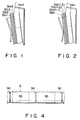
- the order of the boarding passes is designated by the user, i.e., the airline, in seat number order, such as from the lowest to the highest seat number, as shown in Fig. 1, or, as is shown in Fig. 2, from the highest to the lowest seat number.
- the seat numbers are indicated as SN1, SN2, ... SNn.
- the passenger counter is, in some cases, shared by some air companies, each using the counter for some time for its departure flight.
- the boarding passes issuing device has to supply both demands of order from small to large number of seat and of order from large to small number of seat.
- the memory incorporated in the conventional boarding passes issuing device stores a plurality of flight data items supplied from a host computer of each air company, and these data items are read from the memory in the order the boarding passes have been designated, and are printed on the boarding passes.
- the above-mentioned memory needs to have sufficiently memory capacity large enough to store all needed flight information. Further, since printing process starts after the all flight information supplied from the host computer is stored in the memory, a long time is required for preparing the printing, in comparison with the case where the printing process is achieved directly according to each flight information supplied from the host computer.
- the object of the present invention is to provide a stacker for issuing cards, in which the order the cards are stacked having recorded information can be changed easily.
- the solution of this object is achieved by the features of claim 1.
- a stacker for issuing sets of cards, comprising: a card container for receiving a set of cards, having first and second walls opposing each other; a first ejecting portion for ejecting the cards into the container from the second wall side so that the front of each card faces the first wall; a second ejecting portion for ejecting the cards into the container from the first wall side so that the back of each card faces the second wall; and a feeder for supplying the cards to one of first and second ejecting portions sequentially.
- the order the cards are stacked in the card container can be reversed by selecting an ejecting portion.
- the first ejecting portion When the first ejecting portion is selected, and a set of cards are sequentially supplied into the first ejecting portion from the feeder, the cards are ejected into the container from the second wall side so that the front of each card faces the first wall of the container. After the first card is put into the container, the other cards are stacked sequentially on the back of the card previously put in.
- the second ejecting portion is selected, and a set of cards are sequentially supplied to the second ejecting portion from the feeder, the cards are ejected into the container from the first wall side so that the back of each card faces the second wall of the container.
- the other cards are stacked sequentially on the front of the card previously put in. Namely, in the case where the feeder supplies a set of cards, which have serial numbers printed on the fronts, to the first or second ejecting portion, the cards ejected from the first ejecting portion are stacked in the order reverse to those ejected from the second ejecting portion. Further, the cards can be guided to the first or second wall side and set in the same orientation, without using any complicated mechanism.
- the stacker is used in, for example, a card issuing apparatus, the pieces of information supplied sequentially from an external device can be printed on the cards directly. Accordingly, the pieces of information corresponding to all cards need not be temporarily stored in the memory and read out from the memory in the order the cards should be stacked.
- a boarding pass issuing device according to one embodiment of the present invention will now be described, with reference to Figs. 3 to 7.
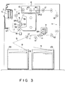
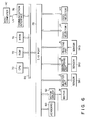
- Fig. 3 schematically shows the internal structure of the boarding pass issuing device and Fig. 4 shows a boarding pass form.
- the boarding pass issuing device has stokers 2a and 2b for holding boarding pass forms 9, a carrier path 11 for the boarding pass forms, a plurality of rollers 12 arranged on the carrier path 11, for carrying the forms 9 along the path 11, a motor M for driving the rollers 12, and paper sensors SR1, SR2 and SR3.
- the boarding pass issuing device contains further comprises a burster unit 3, a magnetic recording unit 4, a printing unit 5, and a stack unit ST -- all located along the carrier path 11.
- Stokers 2a and 2b stores the boarding pass form 9 and are selectively used at the time of issuing the boarding passes.
- the boarding pass forms 9 each include scores 9a marked at fixed intervals and a magnetic stripe 9b formed on back, as is shown in Fig. 4.
- the burster unit 3 cuts each form 9 supplied from either the stocker 2a or 2b along with the score 9a.
- the magnetic recording unit 4 records the flight information on a magnetic stripe 9b of the form 9 supplied from the burster unit 3.
- the printing unit 5 prints the flight information on the front of the form 9 supplied from the magnetic recording unit 4.
- the stack unit ST stacks, in a specific orientation the forms 9 sequentially supplied, as the boarding passes from the printing unit 5.
- the magnetic recording unit 4 comprises a write head 4a and a read-out head 4b.
- the printing unit 5 comprises a printing head 5a, a platen 5b, an ink ribbon 5c, and a printing density sensor 5d.
- Fig. 5 shows a stack unit ST in detail.
- the stack unit ST has a storage 6 for receiving the boarding passes, a void bin 7 for receiving defective boarding passes, first and second ejecting rollers 13a, 13b, for ejecting the boarding passes 9 into the storage 6, first and second ejecting paths 21 and 31 for leading the boarding passes 9 into the first and second ejecting rollers 13a and 13b, a first feed selector V1 for supplying the boarding passes 9 into the first ejecting path 21 or the second ejecting 31, and a second feed selector V2 for supplying the boarding passes 9 into one of the storage 6 and the void pin 7.
- the storage 6 has first and second guides 6a and 6b and a holder 6 located under the guides 6a and 6b.
- the first guide 6a and one portion 6c-a of holder 6c form the first wall W1 of the storage 6, and the second guide 6b and the one portion 6c-2 of holder 6 form the second wall W2 of the storage 6.
- the first wall W1 opposes the second wall W2.
- First and second slots SL1 and SL2 are formed in the walls W1 and W2, respectively.
- the guide 6a is formed integrally with the one portion of second ejecting path 31 as shown in Fig. 5.
- the first and second ejecting rollers 13a and 13b are provided at one end of the first and second ejecting paths 21 and 31, respectively.
- the ejecting paths 21 and 31 are connected at the other end to the carrier path 11 as a branch path.
- the first feed selector V1 comprises a solenoid 42, a flap 43, and an arm 44.
- the flap 43 is rotatable around a shaft SH1 located at the position where the ejecting paths 21 and 31 are connected to the carrier path 11.
- the flap 43 is connected to the solenoid 42 through the arm 44.
- the solenoid 42 is driven to set the flap 43 into an operative position as is shown by the solid line, or into a rest position as is shown by the two-dot, one-dash line.
- the boarding pass 9 is guided from the carrier path 11 to the first ejecting path 21 when the flap 44 is in the rest position. It is guided from the carrier path 11 to the second ejecting path 31 when the flap 44 is in the operative position.
- the second feed selector V2 comprises a solenoid 52, a flap 53, and an arm 54.
- the flap 53 is rotatable around a shaft SH2 provided in the axis of the ejecting path 21, and the flap 53 is connected to the solenoid 52 by the arm 54.
- the solenoid 52 is driven, setting the flap 53 into an operative position as is shown by the solid line, or into a rest position as is shown by the two-dots, one-dash line.
- the boarding pass 9 is guided from the ejecting path 21 to the storage 6 when the flap 54 is in the rest position. It is guided from the carrier path 21 to the void bin 7 when the flap 44 is in the operative position.
- the first and second ejecting rollers 13a and 13b are connected by a belt to the motor M shown in Fig. 3.
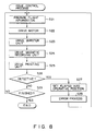
- Fig. 6 is a diagram showing the control circuit of the boarding pass issuing device.
- the control circuit has CPU 70, ROM 72, RAM 74, a communication interface 76, an I/O port 78, a keyboard 80, and a motor driver 82.
- the CPU 70, ROM 72, RAM 74, and communication interface 76 are connected to the I/O port 78 through a bus BS2.
- the communication interface 76 is connected to the host computer HC of the air company through a communication line LN.
- the I/O port 78 is connected to the keyboard 80, motor driver 82, burster unit 3, magnetic recording unit 4, printing unit 5, and first and second feed selectors V1 and V2.
- the sensors SR1, SR2 and SR3 are connected to the burster unit 3, magnetic recording unit 4, and printing unit 5, respectively.
- the ROM 72 stores a control program and fixed data for the CPU 70.
- the RAM 74 stores variable data which is input to and output from the CPU 70.
- the CPU 70 performs various calculating operations and control operations, by executing the control program stored in ROM 72.
- the fixed data includes, for example, the order of boarding passes designated by the air companies.
- the variable data includes, for example, the number of boarding passes and flight information to be issued.
- the flight information is stored from the host computer HC into RAM 70 during the process for issuing the boarding passes HC.
- the keyboard 80 is operated, for example, to designate the air companies, to input flight number of the departure flight, to change the order of boarding passes based on the decision of the operator, and to direct the issuance of boarding passes.
- the burster unit 3, the magnetic recording unit 4, and the printing unit 5 are actuated after the corresponding sensors SR1, SR2 and SR3 detect a form.
- step S1 each circuit element is initialized, and as to whether the order of issuing boarding pass is input or not is checked in step S2. In the case where the order is not input, the other processings are achieved in the step S3, and again step S2 is performed. In the case where the order is input, one of the air companies is selected in step S4, and the control circuit is connected to the host computer HC of the selected air company, whereby the flight number is supplied in accordance with the keyed input in step S5.
- step S6 the order of boarding passes corresponding to the selected air company is preset, and the number of boarding passes to be issued corresponding to the flight number is preset.
- step S7 checks it is determined whether the resulting order is positive or not. If it is positive, the flap 43 is set into the rest position in step S8. If it is not positive, the flap 43 is set into the operative position in step S9.
- step S10 the flap 53 is set into the rest position, and the issuance of the boarding pass is controlled in the step S11.
- Fig. 8 explains how the issuing of boarding passes is controlled.
- First the flight information is prepared in step S21.
- the motor M is driven in step S22.
- the burster unit 3 is driven in step S23.
- the magnetic recording unit 4 is driven in step S24.
- the printing unit 5 is driven in step S25.
- step S26 it is checked as to whether the defective boarding pass is detected by the read-out head 4b and the print density sensor 5d. If such a defective pass is detected, the flap 53 is set into the operative position in step S26, and the process returns to the step S21 after an error process is finished in step S27. If such a defective pass is not detected, it is checked in step S28 as to whether all boarding passes are issued. If all boarding passes are not finished, step S21 is again performed for next issuance of boarding passes. If all boarding passes are finished, the host computer HC is released to stop the motor M, and the process returns to the step S2 as shown in Fig. 7.
- the burster unit 3 cuts the boarding pass forms sequentially supplied from, for example, the stocker 2a.
- Each boarding pass form is supplied to the stack unit ST through the carrier path 11, further through the magnetic recording unit 4 and the printing unit 5.
- the magnetic recording unit 4 records the flight information on the magnetic strip formed on the backs of the boarding passes form supplied from the burster unit 3 sequentially in the order of the seat numbers.
- the printing unit 5 prints the same flight information on the front surfaces of the boarding pass forms sequentially supplied from the magnetic recording unit 4.
- the stack unit ST receives the boarding pass forms sequentially supplied from the printing unit.
- each boarding pass is guided into the first ejecting path 21 by the flap 43 of the first feed selector V1, and is ejected from the ejecting roller 13a.
- the pass, thus ejected, is guided into the storage 6 by the flap 53 through the slap SL2. It is lifted temporarily along the guide 6a by the rotating force of the ejecting roller 13a, and then drops to onto the holder 6c.
- the first boarding pass is put in, with its front facing the wall W1, the next boarding pass is put similarly and is stacked on the back of the previously ejected boarding pass.
- each boarding pass is guided into the second ejecting path 31 by the flap 43 of the first feed selector V1, and is ejected from the ejecting roller 13b.
- the pass, thus ejected, is guided into the storage 6 through the slot SL2. It is lifted temporarily along the guide 6b by the rotating force of the ejecting roller 13b and drops onto the holder 6c.
- the first boarding pass is put in, with its back facing the wall W2
- the next boarding pass is put similarly and is stacked on the front of the previously ejected boarding pass.
- the defective boarding pass is guided into the second ejecting path 31 by the flap 43 of the first feed selector V1 and is ejected from the ejecting roller 13b.
- the ejected boarding pass is guided by the flap 53 and put in the void bin 7.
- the present embodiment it is possible to record the flight information sequentially supplied from the external host computer HC, directly on the plurality of the boarding passes. Accordingly, the flight information corresponding to all boarding passes need not be temporarily stored in the memory, and the flight information need not be read out from the memory in the order the boarding passes should be stacked.
Landscapes
- Engineering & Computer Science (AREA)
- Mechanical Engineering (AREA)
- Conveying Record Carriers (AREA)
- Ticket-Dispensing Machines (AREA)
- Separation, Sorting, Adjustment, Or Bending Of Sheets To Be Conveyed (AREA)
Description
- The present invention relates to a stacker for stacking a plurality of cards to be issued in a desired order, according to the preamble part of
claim 1. Such a stacker is known from JP-A-58-42 553. - All airlines operate a boarding procedure for departing flights, and issue the required number of boarding passes to passengers by means of a boarding pass issuing device. The boarding passes each include flight information comprising the flight number, flight departure time, passenger seat number, the passenger's name, and other details.
- In the case of a conventional boarding pass issuing device, a continuous form is cut at fixed intervals, the relevant flight information being printed on the front surface of each cut form, and a printed card being conveyed to a container as a boarding pass. When a given set of boarding passes is printed, the boarding passes are stacked sequentially in a container such that the front of each one faces the back of the one immediately preceding it. The boarding passes are removed from the container after the final one of the set has been conveyed thereto. The order of the boarding passes is designated by the user, i.e., the airline, in seat number order, such as from the lowest to the highest seat number, as shown in Fig. 1, or, as is shown in Fig. 2, from the highest to the lowest seat number. In Figs. 1 and 2, the seat numbers are indicated as SN1, SN2, ... SNn.
- Recently, the passenger counter is, in some cases, shared by some air companies, each using the counter for some time for its departure flight. In this case, the boarding passes issuing device has to supply both demands of order from small to large number of seat and of order from large to small number of seat. The memory incorporated in the conventional boarding passes issuing device stores a plurality of flight data items supplied from a host computer of each air company, and these data items are read from the memory in the order the boarding passes have been designated, and are printed on the boarding passes.
- The above-mentioned memory needs to have sufficiently memory capacity large enough to store all needed flight information. Further, since printing process starts after the all flight information supplied from the host computer is stored in the memory, a long time is required for preparing the printing, in comparison with the case where the printing process is achieved directly according to each flight information supplied from the host computer.
- The object of the present invention is to provide a stacker for issuing cards, in which the order the cards are stacked having recorded information can be changed easily. The solution of this object is achieved by the features of
claim 1. - According to the present invention, there is provided a stacker for issuing sets of cards, comprising: a card container for receiving a set of cards, having first and second walls opposing each other; a first ejecting portion for ejecting the cards into the container from the second wall side so that the front of each card faces the first wall; a second ejecting portion for ejecting the cards into the container from the first wall side so that the back of each card faces the second wall; and a feeder for supplying the cards to one of first and second ejecting portions sequentially.
- The order the cards are stacked in the card container can be reversed by selecting an ejecting portion. When the first ejecting portion is selected, and a set of cards are sequentially supplied into the first ejecting portion from the feeder, the cards are ejected into the container from the second wall side so that the front of each card faces the first wall of the container. After the first card is put into the container, the other cards are stacked sequentially on the back of the card previously put in. On the other hand, when the second ejecting portion is selected, and a set of cards are sequentially supplied to the second ejecting portion from the feeder, the cards are ejected into the container from the first wall side so that the back of each card faces the second wall of the container. After the first card is put into the container, the other cards are stacked sequentially on the front of the card previously put in. Namely, in the case where the feeder supplies a set of cards, which have serial numbers printed on the fronts, to the first or second ejecting portion, the cards ejected from the first ejecting portion are stacked in the order reverse to those ejected from the second ejecting portion. Further, the cards can be guided to the first or second wall side and set in the same orientation, without using any complicated mechanism.
- If the stacker is used in, for example, a card issuing apparatus, the pieces of information supplied sequentially from an external device can be printed on the cards directly. Accordingly, the pieces of information corresponding to all cards need not be temporarily stored in the memory and read out from the memory in the order the cards should be stacked.
- Figs. 1 and 2 illustrate boarding passes stacked in the container of a conventional boarding pass issuing device in the ascending order of seat numbers and in the descending order thereof, respectively;
- Fig. 3 is a schematic view showing the internal structure of the boarding pass issuing device according to one embodiment of the present invention;
- Fig. 4 illustrates for the boarding pass form put in a stocker of Fig. 3;
- Fig. 5 illustrates the structure of the stack portion of Fig. 3, in greater detail;
- Fig. 6 is a diagram showing the control circuit of the device of Fig. 3; and
- Figs. 7 and 8 are flow charts explaining the operation of the device of Fig. 3.
- A boarding pass issuing device according to one embodiment of the present invention will now be described, with reference to Figs. 3 to 7.
- Fig. 3 schematically shows the internal structure of the boarding pass issuing device and Fig. 4 shows a boarding pass form. The boarding pass issuing device has
stokers 2a and 2b for holdingboarding pass forms 9, acarrier path 11 for the boarding pass forms, a plurality ofrollers 12 arranged on thecarrier path 11, for carrying theforms 9 along thepath 11, a motor M for driving therollers 12, and paper sensors SR1, SR2 and SR3. The boarding pass issuing device contains further comprises aburster unit 3, amagnetic recording unit 4, aprinting unit 5, and a stack unit ST -- all located along thecarrier path 11. Stokers 2a and 2b stores theboarding pass form 9 and are selectively used at the time of issuing the boarding passes. Theboarding pass forms 9 each includescores 9a marked at fixed intervals and amagnetic stripe 9b formed on back, as is shown in Fig. 4. Theburster unit 3 cuts eachform 9 supplied from either thestocker 2a or 2b along with thescore 9a. Themagnetic recording unit 4 records the flight information on amagnetic stripe 9b of theform 9 supplied from theburster unit 3. Theprinting unit 5 prints the flight information on the front of theform 9 supplied from themagnetic recording unit 4. The stack unit ST stacks, in a specific orientation theforms 9 sequentially supplied, as the boarding passes from theprinting unit 5. Themagnetic recording unit 4 comprises a writehead 4a and a read-out head 4b. Theprinting unit 5 comprises aprinting head 5a, aplaten 5b, an ink ribbon 5c, and aprinting density sensor 5d. - Fig. 5 shows a stack unit ST in detail. The stack unit ST has a
storage 6 for receiving the boarding passes, avoid bin 7 for receiving defective boarding passes, first andsecond ejecting rollers boarding passes 9 into thestorage 6, first andsecond ejecting paths boarding passes 9 into the first andsecond ejecting rollers first ejecting path 21 or the second ejecting 31, and a second feed selector V2 for supplying the boarding passes 9 into one of thestorage 6 and thevoid pin 7. Thestorage 6 has first andsecond guides 6a and 6b and aholder 6 located under theguides 6a and 6b. The first guide 6a and one portion 6c-a of holder 6c form the first wall W1 of thestorage 6, and thesecond guide 6b and the one portion 6c-2 ofholder 6 form the second wall W2 of thestorage 6. The first wall W1 opposes the second wall W2. First and second slots SL1 and SL2 are formed in the walls W1 and W2, respectively. The guide 6a is formed integrally with the one portion ofsecond ejecting path 31 as shown in Fig. 5. - The first and second ejecting
rollers second ejecting paths ejecting paths carrier path 11 as a branch path. The first feed selector V1 comprises asolenoid 42, aflap 43, and anarm 44. Theflap 43 is rotatable around a shaft SH1 located at the position where theejecting paths carrier path 11. Theflap 43 is connected to thesolenoid 42 through thearm 44. Thesolenoid 42 is driven to set theflap 43 into an operative position as is shown by the solid line, or into a rest position as is shown by the two-dot, one-dash line. Theboarding pass 9 is guided from thecarrier path 11 to thefirst ejecting path 21 when theflap 44 is in the rest position. It is guided from thecarrier path 11 to thesecond ejecting path 31 when theflap 44 is in the operative position. The second feed selector V2 comprises asolenoid 52, aflap 53, and anarm 54. Theflap 53 is rotatable around a shaft SH2 provided in the axis of theejecting path 21, and theflap 53 is connected to thesolenoid 52 by thearm 54. Thesolenoid 52 is driven, setting theflap 53 into an operative position as is shown by the solid line, or into a rest position as is shown by the two-dots, one-dash line. Theboarding pass 9 is guided from theejecting path 21 to thestorage 6 when theflap 54 is in the rest position. It is guided from thecarrier path 21 to thevoid bin 7 when theflap 44 is in the operative position. The first andsecond ejecting rollers - Fig. 6 is a diagram showing the control circuit of the boarding pass issuing device. The control circuit has
CPU 70,ROM 72,RAM 74, acommunication interface 76, an I/O port 78, akeyboard 80, and amotor driver 82. TheCPU 70,ROM 72,RAM 74, andcommunication interface 76 are connected to the I/O port 78 through a bus BS2. Thecommunication interface 76 is connected to the host computer HC of the air company through a communication line LN. The I/O port 78 is connected to thekeyboard 80,motor driver 82,burster unit 3,magnetic recording unit 4,printing unit 5, and first and second feed selectors V1 and V2. The sensors SR1, SR2 and SR3 are connected to theburster unit 3,magnetic recording unit 4, andprinting unit 5, respectively. TheROM 72 stores a control program and fixed data for theCPU 70. TheRAM 74 stores variable data which is input to and output from theCPU 70. TheCPU 70 performs various calculating operations and control operations, by executing the control program stored inROM 72. The fixed data includes, for example, the order of boarding passes designated by the air companies. The variable data includes, for example, the number of boarding passes and flight information to be issued. The flight information is stored from the host computer HC intoRAM 70 during the process for issuing the boarding passes HC. Thekeyboard 80 is operated, for example, to designate the air companies, to input flight number of the departure flight, to change the order of boarding passes based on the decision of the operator, and to direct the issuance of boarding passes. Theburster unit 3, themagnetic recording unit 4, and theprinting unit 5 are actuated after the corresponding sensors SR1, SR2 and SR3 detect a form. - The operation of this boarding pass issuing device will be explained, with reference to Figs. 7 and 8. When the issuing device is turned to ON,
CPU 70 starts it's processings as shown in Fig. 7. At the first step S1, each circuit element is initialized, and as to whether the order of issuing boarding pass is input or not is checked in step S2. In the case where the order is not input, the other processings are achieved in the step S3, and again step S2 is performed. In the case where the order is input, one of the air companies is selected in step S4, and the control circuit is connected to the host computer HC of the selected air company, whereby the flight number is supplied in accordance with the keyed input in step S5. In step S6, the order of boarding passes corresponding to the selected air company is preset, and the number of boarding passes to be issued corresponding to the flight number is preset. In step S7 checks it is determined whether the resulting order is positive or not. If it is positive, theflap 43 is set into the rest position in step S8. If it is not positive, theflap 43 is set into the operative position in step S9. In step S10, theflap 53 is set into the rest position, and the issuance of the boarding pass is controlled in the step S11. - Fig. 8 explains how the issuing of boarding passes is controlled. First the flight information is prepared in step S21. The motor M is driven in step S22. the the
burster unit 3 is driven in step S23. Themagnetic recording unit 4 is driven in step S24. Theprinting unit 5 is driven in step S25. In step S26, it is checked as to whether the defective boarding pass is detected by the read-outhead 4b and theprint density sensor 5d. If such a defective pass is detected, theflap 53 is set into the operative position in step S26, and the process returns to the step S21 after an error process is finished in step S27. If such a defective pass is not detected, it is checked in step S28 as to whether all boarding passes are issued. If all boarding passes are not finished, step S21 is again performed for next issuance of boarding passes. If all boarding passes are finished, the host computer HC is released to stop the motor M, and the process returns to the step S2 as shown in Fig. 7. - In this embodiment, the
burster unit 3 cuts the boarding pass forms sequentially supplied from, for example, the stocker 2a. Each boarding pass form is supplied to the stack unit ST through thecarrier path 11, further through themagnetic recording unit 4 and theprinting unit 5. Themagnetic recording unit 4 records the flight information on the magnetic strip formed on the backs of the boarding passes form supplied from theburster unit 3 sequentially in the order of the seat numbers. Theprinting unit 5 prints the same flight information on the front surfaces of the boarding pass forms sequentially supplied from themagnetic recording unit 4. The stack unit ST receives the boarding pass forms sequentially supplied from the printing unit. - In the case where the order of the boarding pass is positive, each boarding pass is guided into the
first ejecting path 21 by theflap 43 of the first feed selector V1, and is ejected from the ejectingroller 13a. The pass, thus ejected, is guided into thestorage 6 by theflap 53 through the slap SL2. It is lifted temporarily along the guide 6a by the rotating force of the ejectingroller 13a, and then drops to onto the holder 6c. When the first boarding pass is put in, with its front facing the wall W1, the next boarding pass is put similarly and is stacked on the back of the previously ejected boarding pass. - On the other hand, when the order of the boarding pass is not positive, each boarding pass is guided into the
second ejecting path 31 by theflap 43 of the first feed selector V1, and is ejected from the ejectingroller 13b. The pass, thus ejected, is guided into thestorage 6 through the slot SL2. It is lifted temporarily along theguide 6b by the rotating force of the ejectingroller 13b and drops onto the holder 6c. When the first boarding pass is put in, with its back facing the wall W2, the next boarding pass is put similarly and is stacked on the front of the previously ejected boarding pass. - The defective boarding pass is guided into the
second ejecting path 31 by theflap 43 of the first feed selector V1 and is ejected from the ejectingroller 13b. The ejected boarding pass is guided by theflap 53 and put in thevoid bin 7. - With the present embodiment, it is possible to record the flight information sequentially supplied from the external host computer HC, directly on the plurality of the boarding passes. Accordingly, the flight information corresponding to all boarding passes need not be temporarily stored in the memory, and the flight information need not be read out from the memory in the order the boarding passes should be stacked.
Claims (7)
- A stacker for stacking sets of cards, the cards having front and back surfaces, comprising:
a card container (6) for receiving a set of cards, said card container having first and second spaced apart walls (W1, W2) opposing each other;
first ejecting means (21, 13a) for ejecting the cards into said card container (6) from the second wall side of the card container (6);
second ejecting means (31, 13b) for ejecting the cards into said card container (6) from the first wall side of said card container (6); and
feeding means (70, 11, V1) for supplying the cards to one of said first and second ejecting means sequentially;
characterized in that
first and second slots (SL1, SL2) are respectively formed within said first and second walls (W1, W2), said first ejecting means (21, 13a) ejects the cards from said second slot (SL2) with the front surfaces of the cards facing the first wall (W1) to thereby arrange the cards in a direction from said first wall side to said second wall side with the front surfaces of each card facing said first wall (W1), and said second ejecting means (31, 13b) ejects the cards from said first slot (SL1) with the front surfaces of the cards facing said first wall (W1) to thereby arrange the cards in a direction from said second wall side to said first wall side with the front surfaces of each card facing said first wall (W1). - A stacker according to claim 1, characterized in that said feeding means includes stack control means (70) for determining an order of the set of cards and allowing the cards to be supplied to the ejecting means (21, 13a; 31, 13b) corresponding to the order.
- A stacker according to claim 2, characterized in that said first ejecting means includes a first ejector (21, 13a) for ejecting cards into said container (6) through said second slot (SL2), and said second ejecting means includes a second ejector (31, 13b) for ejecting cards into said container (6) through said first slot (SL1).
- A stacker according to claim 3, characterized in that said first ejector includes a pair of ejecting rollers (13a) located adjacent to said second slot (SL2) and an ejecting path (21) formed between the ejecting roller pair (13a) thereof and said feeding means (70, 11, V1), and said second ejector includes a pair of ejecting rollers (13b) located adjacent to said first slot (SL1) and an ejecting path (31) formed between the ejecting roller pair (13b) thereof and said feeding means (70,11, V1).
- A stacker according to claim 4, characterized in that said feeding means includes means defining a feeding path (11) connected to the ejecting paths (21, 31) of said first and second ejectors (21, 13a; 31, 13b), and a flap (43) located at a position where said feeding path (11) is connected to said ejecting path (21, 31), for guiding cards supplied from said feeding path (11) to one of the ejecting paths (21, 31) of said first and second ejectors (21, 13a; 31, 13b).
- A stacker according to claim 2, characterized in that said stack control means includes removing means (V2, 7) for removing defective cards.
- A stacker according to claim 6, characterized in that said removing means includes a void bin (7) for receiving the defective cards, and a flap (53), located between said container (6) and one of said first and second ejecting means (21, 13a; 31, 13b), for guiding the defective cards to said void bin (7).
Applications Claiming Priority (2)
| Application Number | Priority Date | Filing Date | Title |
|---|---|---|---|
| JP232424/89 | 1989-09-07 | ||
| JP1232424A JP2713778B2 (en) | 1989-09-07 | 1989-09-07 | Airline boarding pass issuing machine |
Publications (3)
| Publication Number | Publication Date |
|---|---|
| EP0416633A2 EP0416633A2 (en) | 1991-03-13 |
| EP0416633A3 EP0416633A3 (en) | 1991-07-03 |
| EP0416633B1 true EP0416633B1 (en) | 1994-12-28 |
Family
ID=16939048
Family Applications (1)
| Application Number | Title | Priority Date | Filing Date |
|---|---|---|---|
| EP90117219A Expired - Lifetime EP0416633B1 (en) | 1989-09-07 | 1990-09-06 | Stacker for stacking and issuing sets of cards |
Country Status (4)
| Country | Link |
|---|---|
| US (1) | US5104115A (en) |
| EP (1) | EP0416633B1 (en) |
| JP (1) | JP2713778B2 (en) |
| DE (1) | DE69015520T2 (en) |
Families Citing this family (5)
| Publication number | Priority date | Publication date | Assignee | Title |
|---|---|---|---|---|
| DE69621553T2 (en) * | 1995-10-17 | 2003-01-16 | Sharp Kk | Sheet output device |
| JP3648073B2 (en) | 1998-05-29 | 2005-05-18 | シャープ株式会社 | Sheet post-processing device |
| US6769862B1 (en) | 2002-12-03 | 2004-08-03 | Jeffrey B. Kuhl | Apparatus and method for placing horizontally oriented flats into vertically extending stacks thereof |
| FR2864670B1 (en) * | 2003-12-29 | 2007-04-27 | A S K | METHOD FOR DISTRIBUTING AND CUSTOMIZING CONTACTLESS CHIP TICKETS AND DEVICE THEREOF |
| US11046546B2 (en) | 2018-01-30 | 2021-06-29 | Seiko Epson Corporation | Medium discharge device and recording apparatus |
Family Cites Families (9)
| Publication number | Priority date | Publication date | Assignee | Title |
|---|---|---|---|---|
| GB1461554A (en) * | 1975-04-08 | 1977-01-13 | Wicks Wilson Ltd | Microfilm card duplication |
| US4220323A (en) * | 1979-08-08 | 1980-09-02 | Eastman Kodak Company | Sheet receiving and stacking apparatus |
| JPS5781051A (en) * | 1980-11-07 | 1982-05-20 | Hitachi Ltd | Apparatus for arranging all fronts of sheets of paper orderly to face upward |
| DE3047277A1 (en) * | 1980-12-16 | 1982-07-15 | Philips Patentverwaltung Gmbh, 2000 Hamburg | "STORAGE DEVICE FOR DATA CARRIER" |
| JPS5842553A (en) * | 1981-09-01 | 1983-03-12 | Omron Tateisi Electronics Co | Apparatus for piling paper sheet face to face |
| DE3228620A1 (en) * | 1982-07-30 | 1984-02-02 | Siemens AG, 1000 Berlin und 8000 München | DEVICE FOR LINE PRINTING DEVICES FOR THE STORAGE OF SHEET-SHAPED RECORDING CARRIERS |
| US4570801A (en) * | 1984-03-21 | 1986-02-18 | Brannen Ralph L | Document handling machine |
| NL8503006A (en) * | 1985-11-04 | 1987-06-01 | Oce Nederland Bv | METHOD AND APPARATUS FOR PRINTING IMAGES ON HALF OF BOTH SIDES OF SHEETS. |
| JPH0782556B2 (en) * | 1986-11-28 | 1995-09-06 | 株式会社テック | Ticket issuing machine |
-
1989
- 1989-09-07 JP JP1232424A patent/JP2713778B2/en not_active Expired - Fee Related
-
1990
- 1990-09-05 US US07/577,902 patent/US5104115A/en not_active Expired - Lifetime
- 1990-09-06 EP EP90117219A patent/EP0416633B1/en not_active Expired - Lifetime
- 1990-09-06 DE DE69015520T patent/DE69015520T2/en not_active Expired - Fee Related
Also Published As
| Publication number | Publication date |
|---|---|
| US5104115A (en) | 1992-04-14 |
| EP0416633A3 (en) | 1991-07-03 |
| JP2713778B2 (en) | 1998-02-16 |
| JPH0394396A (en) | 1991-04-19 |
| EP0416633A2 (en) | 1991-03-13 |
| DE69015520T2 (en) | 1995-05-04 |
| DE69015520D1 (en) | 1995-02-09 |
Similar Documents
| Publication | Publication Date | Title |
|---|---|---|
| US4909648A (en) | Processor for forms with multi-format data | |
| US4895466A (en) | Processor for forms with multi-format data | |
| JPH11209007A (en) | Method to distribute printing document and supply to finishing device | |
| EP0416633B1 (en) | Stacker for stacking and issuing sets of cards | |
| EP0095737B1 (en) | Destination label printer | |
| JP2563608B2 (en) | Paper feeder of ticket issuing machine | |
| JP2919052B2 (en) | Ticket issuing device | |
| JP2534365B2 (en) | Continuous paper loading device for ticket issuing machine | |
| JP2553355B2 (en) | Ticket processing terminal device | |
| JP2813198B2 (en) | Ticket issuing device | |
| JPH0743781B2 (en) | Ticket processing terminal device | |
| JP2545863B2 (en) | Ticket processing terminal device | |
| JPH012195A (en) | Ticket processing terminal device | |
| JPH0664639B2 (en) | Ticket processing terminal device | |
| JPH06124373A (en) | Issuing device for many kind of tickets | |
| JPH011091A (en) | Ticket processing terminal device | |
| JPH0743780B2 (en) | Ticket processing terminal device | |
| JP2608983B2 (en) | How to issue multiple types of media | |
| JP2647248B2 (en) | Ticket issuing device | |
| JPH0743782B2 (en) | Ticket processing terminal device | |
| JPH011094A (en) | Ticket processing terminal device | |
| JPH011092A (en) | Ticket processing terminal device | |
| JP2002073290A (en) | Recording system and recording method | |
| JPH012194A (en) | Ticket processing terminal device | |
| JPH012193A (en) | Ticket processing terminal device |
Legal Events
| Date | Code | Title | Description |
|---|---|---|---|
| PUAI | Public reference made under article 153(3) epc to a published international application that has entered the european phase |
Free format text: ORIGINAL CODE: 0009012 |
|
| 17P | Request for examination filed |
Effective date: 19900906 |
|
| AK | Designated contracting states |
Kind code of ref document: A2 Designated state(s): DE FR GB SE |
|
| PUAL | Search report despatched |
Free format text: ORIGINAL CODE: 0009013 |
|
| AK | Designated contracting states |
Kind code of ref document: A3 Designated state(s): DE FR GB SE |
|
| 17Q | First examination report despatched |
Effective date: 19930402 |
|
| GRAA | (expected) grant |
Free format text: ORIGINAL CODE: 0009210 |
|
| AK | Designated contracting states |
Kind code of ref document: B1 Designated state(s): DE FR GB SE |
|
| PG25 | Lapsed in a contracting state [announced via postgrant information from national office to epo] |
Ref country code: FR Effective date: 19941228 |
|
| REF | Corresponds to: |
Ref document number: 69015520 Country of ref document: DE Date of ref document: 19950209 |
|
| PG25 | Lapsed in a contracting state [announced via postgrant information from national office to epo] |
Ref country code: SE Effective date: 19950328 |
|
| EN | Fr: translation not filed | ||
| PLBE | No opposition filed within time limit |
Free format text: ORIGINAL CODE: 0009261 |
|
| STAA | Information on the status of an ep patent application or granted ep patent |
Free format text: STATUS: NO OPPOSITION FILED WITHIN TIME LIMIT |
|
| 26N | No opposition filed | ||
| PGFP | Annual fee paid to national office [announced via postgrant information from national office to epo] |
Ref country code: GB Payment date: 19960828 Year of fee payment: 7 |
|
| PGFP | Annual fee paid to national office [announced via postgrant information from national office to epo] |
Ref country code: DE Payment date: 19960913 Year of fee payment: 7 |
|
| PG25 | Lapsed in a contracting state [announced via postgrant information from national office to epo] |
Ref country code: GB Free format text: LAPSE BECAUSE OF NON-PAYMENT OF DUE FEES Effective date: 19970906 |
|
| GBPC | Gb: european patent ceased through non-payment of renewal fee |
Effective date: 19970906 |
|
| PG25 | Lapsed in a contracting state [announced via postgrant information from national office to epo] |
Ref country code: DE Free format text: LAPSE BECAUSE OF NON-PAYMENT OF DUE FEES Effective date: 19980603 |