EP0414075A1 - Device for filling containers - Google Patents
Device for filling containers Download PDFInfo
- Publication number
- EP0414075A1 EP0414075A1 EP90115441A EP90115441A EP0414075A1 EP 0414075 A1 EP0414075 A1 EP 0414075A1 EP 90115441 A EP90115441 A EP 90115441A EP 90115441 A EP90115441 A EP 90115441A EP 0414075 A1 EP0414075 A1 EP 0414075A1
- Authority
- EP
- European Patent Office
- Prior art keywords
- storage container
- metering chamber
- container
- liquid
- return gas
- Prior art date
- Legal status (The legal status is an assumption and is not a legal conclusion. Google has not performed a legal analysis and makes no representation as to the accuracy of the status listed.)
- Granted
Links
- 239000007788 liquid Substances 0.000 claims abstract description 106
- 238000007789 sealing Methods 0.000 claims abstract description 26
- 238000003032 molecular docking Methods 0.000 claims description 7
- 238000006073 displacement reaction Methods 0.000 abstract description 7
- 230000008878 coupling Effects 0.000 abstract 1
- 238000010168 coupling process Methods 0.000 abstract 1
- 238000005859 coupling reaction Methods 0.000 abstract 1
- 238000005429 filling process Methods 0.000 description 14
- CURLTUGMZLYLDI-UHFFFAOYSA-N Carbon dioxide Chemical compound O=C=O CURLTUGMZLYLDI-UHFFFAOYSA-N 0.000 description 4
- 238000005187 foaming Methods 0.000 description 4
- 238000000034 method Methods 0.000 description 3
- 230000002093 peripheral effect Effects 0.000 description 3
- 230000015572 biosynthetic process Effects 0.000 description 2
- 229910002092 carbon dioxide Inorganic materials 0.000 description 2
- 235000014171 carbonated beverage Nutrition 0.000 description 2
- 238000010276 construction Methods 0.000 description 2
- 230000000694 effects Effects 0.000 description 2
- 230000036316 preload Effects 0.000 description 2
- 230000005587 bubbling Effects 0.000 description 1
- 239000001569 carbon dioxide Substances 0.000 description 1
- 230000003247 decreasing effect Effects 0.000 description 1
- 230000001419 dependent effect Effects 0.000 description 1
- 230000008030 elimination Effects 0.000 description 1
- 238000003379 elimination reaction Methods 0.000 description 1
- 230000005484 gravity Effects 0.000 description 1
- 238000007654 immersion Methods 0.000 description 1
- 230000010354 integration Effects 0.000 description 1
Images


Classifications
-
- B—PERFORMING OPERATIONS; TRANSPORTING
- B67—OPENING, CLOSING OR CLEANING BOTTLES, JARS OR SIMILAR CONTAINERS; LIQUID HANDLING
- B67C—CLEANING, FILLING WITH LIQUIDS OR SEMILIQUIDS, OR EMPTYING, OF BOTTLES, JARS, CANS, CASKS, BARRELS, OR SIMILAR CONTAINERS, NOT OTHERWISE PROVIDED FOR; FUNNELS
- B67C3/00—Bottling liquids or semiliquids; Filling jars or cans with liquids or semiliquids using bottling or like apparatus; Filling casks or barrels with liquids or semiliquids
- B67C3/02—Bottling liquids or semiliquids; Filling jars or cans with liquids or semiliquids using bottling or like apparatus
- B67C3/20—Bottling liquids or semiliquids; Filling jars or cans with liquids or semiliquids using bottling or like apparatus with provision for metering the liquids to be introduced, e.g. when adding syrups
- B67C3/204—Bottling liquids or semiliquids; Filling jars or cans with liquids or semiliquids using bottling or like apparatus with provision for metering the liquids to be introduced, e.g. when adding syrups using dosing chambers
-
- B—PERFORMING OPERATIONS; TRANSPORTING
- B67—OPENING, CLOSING OR CLEANING BOTTLES, JARS OR SIMILAR CONTAINERS; LIQUID HANDLING
- B67C—CLEANING, FILLING WITH LIQUIDS OR SEMILIQUIDS, OR EMPTYING, OF BOTTLES, JARS, CANS, CASKS, BARRELS, OR SIMILAR CONTAINERS, NOT OTHERWISE PROVIDED FOR; FUNNELS
- B67C3/00—Bottling liquids or semiliquids; Filling jars or cans with liquids or semiliquids using bottling or like apparatus; Filling casks or barrels with liquids or semiliquids
- B67C3/02—Bottling liquids or semiliquids; Filling jars or cans with liquids or semiliquids using bottling or like apparatus
- B67C3/22—Details
- B67C3/26—Filling-heads; Means for engaging filling-heads with bottle necks
- B67C2003/2657—Filling-heads; Means for engaging filling-heads with bottle necks specially adapted for filling cans
Definitions
- the invention relates to a device for filling containers, in particular bottles or cans, with a predetermined amount of a liquid.
- a liquid contained in a storage kettle is usually filled into containers, such as cans or bottles, by successively docking the containers to a filling head which is arranged on the storage container and has an outlet closing valve which opens for filling the liquid into the containers becomes.
- the liquid flows from the storage container under the effect of gravity through the open valve into the container to be filled.
- a filling head must be provided, which first pressurizes the container with the pressure which also acts on the liquid in the storage container, so that the container to be filled is pre-stressed before the filling of the liquid is started.
- the biasing gas is displaced from the container.
- the fill level in the container is determined by the position of the end of the vent line in the upper part of the container to be filled. Since the inner volume of the container is usually not constant, precise volume metering of the filling quantity is not possible in this way.
- the invention has for its object to provide a device of the type described above for filling volumetrically measured amounts of a liquid.
- a storage container holding the liquid to be filled and a metering chamber of predetermined volume connected to the storage container via a closable liquid passage, which has a closable liquid outlet and centering and sealing means for docking successive containers to be filled.
- the invention offers the advantage that it allows the filling of precisely specified quantities of a liquid into containers such as cans or bottles to be docked one after the other.
- the filling quantities in successive containers are no longer dependent on the internal volume of the respective container.
- the features of the claims relating to the arrangement of the metering chamber within the storage container are of particular and independent inventive importance. This integration of the dosing chamber into the storage container not only achieves a compact and space-saving construction of the filling device, but also results in a conception of the filling device that is particularly suitable for filling a liquid in the storage container under increased pressure.
- the externally adjustable displacement body which is inserted into the metering chamber in accordance with claims 8 and 9 makes the filling device according to the invention particularly flexible because it can be adjusted to different volumetric quantities which can be determined.
- the features of the claims which relate to the arrangement of the displacement body in the metering chamber, also have independent inventive significance.
- the displacer also serves as an assembly and guide body for several components of the filling device proposed according to the invention and thereby makes the filling head of the device a compact, separately mountable and easy-to-use and adjustable structural unit which can be mounted outside the storage container and inserted as a whole into the storage container.
- the filling device according to the invention is structurally simple and safe in its function because it has only a few moving parts.
- the embodiment according to claim 7 is considered to be particularly advantageous because the inner metering chamber part simultaneously has a valve function for the passage of the liquid to the metering chamber.
- the design of the return gas pipe as the carrier and actuating member of the outlet valve of the metering chamber toward the respective docked container increases the simplicity of the construction of the filling device according to the invention, since additional parts that can be moved relative to each other are saved.
- the filling process can advantageously be accelerated by reducing the internal pressure of the container during filling according to the invention.
- the decreasing filling speed towards the end of the filling process causes the liquid flow to calm down, which reduces the risk of the liquid foaming in the container to be filled.
- the filling head versions in which the dosing chamber is filled from below, ensure that the dosing chamber is filled smoothly and yet quickly without the formation of bubbles and vortices that significantly impair the dosing process.
- the invention provides in a very advantageous manner a filling device for metered filling of liquids with a structurally compact, easy to assemble, handle and adjust and at the same time extremely functionally reliable and fast filling head, which in a particularly advantageous manner also fills under pressure standing liquid allowed.
- the invention advantageously provides an extremely fast filling valve which, with high functional reliability, allows high filling speeds of precisely metered filling quantities.
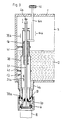
- the filling device shown in FIG. 1 has a storage container 1, which can be designed in a known manner as a ring bowl rotating around a vertical axis (see FIG. 5).
- a liquid 2 to be filled is contained in the ring bowl.
- the liquid level is kept constant by known means, not shown in the drawing.
- Above the liquid level there is a gas space 3 which contains a gas under an increased pressure.
- a pot-shaped container extension 4 is attached to the underside of the storage container 1, the outside of which is designed as a guide for a centering and sealing bell 6.
- the centering and sealing bell 6 has at its lower outlet a seal 7, with which it is pressed onto a container 8 to be filled, for example a can or bottle. Successive containers 8 are held by means of a carrier 9 during the filling process.
- the centering and sealing bell 6 can be moved up and down on the container attachment 4.
- the container attachment 4 has a control roller 11 which is guided up and down in the direction of a double arrow 11a by means of a control cam 11b and thereby moves the centering and sealing bell 6 accordingly.
- the inside of the container neck 4 represents the lower part of a metering chamber 12, the upper part of which is formed by a hollow cylinder 13, which is arranged axially aligned with the container neck 4 in the interior of the storage container 1.
- the hollow end of the hollow cylinder 13 lies around the inner access to the container attachment 4 on the bottom of the storage container 1 and seals the dosing chamber 12 to the liquid 2 by means of a seal 13a.
- the hollow cylinder 13 is axially movable in the direction of an arrow 13b, for which purpose an eccentric 15 actuated by means of a control cam 15a and a control roller 15b is provided, which into a corresponding driver 13c of the hollow cylinder ders engages 13.
- At the lower end of the hollow cylinder 13 there is a cylindrical guide surface 14 projecting into the container shoulder 4, which is intended to even out the flow of the liquid flowing from the storage container 1 into the metering chamber 12.
- a displacer body 16 is inserted into the hollow cylinder 13 from above, which is mounted with a guide rod 16a in the housing of the storage container 1 and is adjustable from the outside in the direction of an arrow 16b.
- the axial position of the displacer 16 in the hollow cylinder 13 determines the filling volume of the metering chamber 12.
- the displacer 16 simultaneously forms the axial guidance of the hollow cylinder 13 in the direction of the double arrow 13b.
- a return gas line 17 runs through the displacement body 16 between the metering chamber 12 and the gas space 3 of the storage container.
- This return gas line 17 has a float valve 18 with a float ball 18a, which limits the fill level of the metering chamber below the liquid level in the reservoir 1.
- a return gas line 19 is also provided between the outside of the cylindrical guide surface 14 and the inside wall of the container attachment 4.
- a return gas pipe 21 is also movably guided in the direction of an arrow 21a.
- an eccentric 25 is provided, which is moved by means of a curve 25a and a control roller 25b and cooperates with drivers 21b.
- This return gas pipe 21 connects the interior of a container 8 docked for filling with the gas space 3 of the storage container 1.
- a valve 22 with a seal 22a is formed, which closes the outlet of the metering chamber to the container.
- a ball check valve 23 is arranged, which closes the gas space 3 of the storage container 1 against atmosphere or lower pressure than that prevailing in the gas space.
- the upper end of the return gas tube 21 corresponds to a return gas connection 24 which is connected via a shuttle valve 26 either to the gas space 3 of the storage container 1 or to an additional gas space 27 which contains a gas under a reduced pressure compared to the gas space 3.
- the gas space 27 forms a structural unit with the storage container 1 and can also be designed as an annular space.
- the shuttle valve 26 is adjustable via an actuator 28 in the direction of an arrow 28 a .
- a pretensioning line 29 is provided which connects the gas space of the storage container 1 to the inside of the centering and sealing bell 6 and the inside of a docked container 8 via a valve 29a .
- the arrangement of the prestressing line is made in the area of the centering and sealing bell 6 in such a way that a differential pressure arises between an annular space 6a in the centering and sealing bell 6 and the interior of the container, which increases the pressure of the seal 7 against the upper edge of the container to be filled .
- a relief valve 31 is used to relax the container 8 after filling with a liquid under increased pressure.
- the storage container 1 contains a carbonated beverage 2 and that the gas in the gas space 3 above the liquid level is under an increased pressure.
- the pressure in the additional gas space 27 is below the pressure in Gas space 3.
- the hollow cylinder 13 lies against the bottom of the storage container 1 via the seal 13a and closes the metering chamber against the liquid 2.
- the liquid outlet 20 of the metering chamber 12 to the container 8 is closed by the valve 22.
- a container 8 is positioned under the centering and sealing bell 6, and the centering and sealing bell is lowered onto the upper edge of the container 8 by means of the control roller 11 and the control cam 11b. Then, by opening the biasing valve 29a, the pressure of the gas in the gas space 3 is applied to the inside of the container 8 so that the container 8 is biased, the differential pressure between the annular space 6a in the centering and sealing bell 6 and the inside of the container 8 the pressure of the seal 7 on the upper container edge is increased.
- the hollow cylinder 13 is then raised in the direction of the arrow 13b, so that the liquid passage 10 between the storage container 1 and the metering chamber is opened and the liquid flows into the metering chamber, the flow of the liquid through the cylindrical guide surface 14 being calmed so that foaming is suppressed.
- the gas contained in the metering chamber 12 escapes when the liquid flows in through the return gas line 17 until the liquid level reached in the metering chamber lifts the float ball 18a and the float valve 18 closes.
- the dosing chamber contains an exactly measured amount of the liquid to be filled.
- the amount of liquid contained in the metering chamber is determined by its volume, which is set with the help of the displacement body 16.
- By axially displacing the displacer body 16 The desired volume of the metering chamber is preset in the direction of arrow 16b.
- the valve 22 at the liquid outlet 20 of the metering chamber is opened to the container 8 after the valve 29a of the prestressing line has been closed.
- the upper end of the return gas pipe is applied to the return gas connection 24.
- the valve 26 is initially set so that via the return gas pipe, the return gas connection 24 and the valve 26 there is first a connection between the inside of the container 8 and the gas space 3 of the storage container 1, so that when the liquid flows out of the metering chamber into the Container 8 displaced gas is first led into the gas space 3.
- valve 26 can be switched by means of the actuator 28 at a predetermined time, so that the inside of the container is connected to the gas space 27 of reduced pressure.
- suction effect which accelerates the filling of the container 8 and thus allows longer cycle times.
- the valve 22 is closed by lowering the return gas pipe in the direction of the arrow 21a.
- the relief valve 31 is then opened, whereby the container is placed at atmospheric pressure.
- the ball check valve 23 closes the back gas pipe 21 and prevents it an out flow of the gas from the gas space 3 of the storage container 1.
- FIG. 2 differs from that of FIG. 1 by a different design of the metering chamber and by the elimination of the additional gas space.
- the same parts are given the same reference numerals in FIG. 2 as in FIG. 1
- a metering chamber 32 is provided, which is formed in one piece as an approximately cylindrical component. It is inserted from below into the storage container 3 and fastened to its underside by means of a flange 33. A part 34 of the metering chamber lying inside the storage container 1 protrudes through the liquid 2 into the gas space 3. In this part 34 of the metering chamber, the displacer 16 is inserted, which is axially displaceable in the direction of arrow 16b to adjust the volume of the metering chamber Contains return gas line 17 with the float valve 18 and serves as a guide for the return gas pipe 21. Outside the storage container 1 is on the underside of the lower metering chamber part 36, the exterior of which, as in the case of FIG.
- the filling process with this embodiment of the filling device is the same as described in connection with the embodiment of FIG. 1.
- the filling head consisting of the metering chamber and the centering and sealing bell, can be pre-assembled in one piece and then inserted into the storage container.
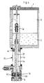
- a dosing chamber 12 is inserted into the storage container 1, which has on its underside a container extension 4a which is connected to the liquid space of the storage container, which is designed as an essentially cylindrical hollow body 39 and is tight on the bottom of the storage container in the container extension 4a sits on.
- a seal 39a In its contact area, with which the dosing chamber contacts the bottom of the container, it is provided with a seal 39a, which seals the liquid space 2 of the storage container from the dosing chamber.
- the hollow body 39 is guided in the storage container 1 in holders 41 in the direction of an arrow 39a so as to be vertically movable. If the hollow body 39 is lifted in the direction of arrow 39b from the bottom of the container attachment 4a, a liquid passage 10 opens, through which the liquid 2 from the storage container from below into the metering chamber 12 flows in. The liquid outlet 20 to the container 8 to be filled in the bottom of the metering chamber is closed in this process.
- the hollow body 39 fills up to the level of the liquid in the reservoir according to the principle of the communicating tubes.
- the volume of the metering chamber 12 is determined by the immersion depth of the displacer 16, which can be predetermined from the outside by means of an adjusting means 42.
- the gas contained in the metering chamber escapes past the displacer body 16 when filling the metering chamber and up through it into the gas space 3 of the storage container.
- the hollow body 39 is lowered to the bottom of the storage container and the liquid passage 10 is thus closed.
- the valve 43 which closes the return gas tube 21 to the gas space 3, is opened for prestressing the container 8.
- the return gas tube is moved upward in the direction of the double arrow 21a, as a result of which the liquid outlet 20 is opened towards the container 8 and the volumetrically measured quantity of liquid in the metering chamber is dispensed into the container 8.
- the gas contained in the container 8 escapes through the return gas pipe 21 into the gas space 3.
- the liquid outlet 20 and the valve 43 are closed again and a new filling process can begin.
- This design and arrangement of the metering chamber 12 has the advantage that the liquid 2 from the reservoir can rise from below in the metering chamber, which largely prevents eddy formation and the foaming of the liquid associated therewith.
- the storage container 1 can be designed as an annular chamber which, along its circumference, carries a whole series of the devices described, to enable continuous filling of successive containers 8.
- Fig. 4 shows yet another embodiment of the device according to the invention in a schematic longitudinal section, wherein again the same parts are provided with the same reference numerals as before.
- the metering chamber 12 is attached to the underside of the storage container 1, wherein the storage container 1 can be designed as an annular bowl on which a number of metering chambers 12 are provided next to one another in the circumferential direction.
- the metering chamber 12 is designed as a cylindrical hollow body 44 which is flanged to the underside of the storage container 1 in the example shown. It carries a centering and sealing bell 6 for docking containers, not shown, to be filled.
- a container extension 46 is arranged in the form of a cylindrical tube piece, which is connected via its upper end to the liquid in the storage container 1 and therefore continuously is filled with liquid.
- the upper end of the metering chamber 12 is formed by a displacer 16, which seals the metering chamber from the liquid 2 in the reservoir 1.
- the container neck 46 is axially displaceably mounted and guided in the displacement body 16.
- the return gas tube 21, which connects the interior of a docked container with the gas space 3 of the storage container 1, is guided longitudinally axially through the container extension 46.
- the return gas tube 21 carries a valve body 47 in the region of its lower end, which fulfills a double function. On the one hand, this valve body 47 closes off the liquid outlet 20 of the metering chamber 12 towards the container to be filled. On the other hand, this valve body 47 forms the bottom of the storage container 1 in the region of the Container neck 46.
- the container neck 46 lies tightly on the valve body 47.
- the liquid passage 10 opens and the liquid 2 flows from the storage container 1 through the container neck 46 into the metering chamber 12, which concentrically surrounds the tube piece forming the container neck 46, the contained in the metering chamber Gas escapes through a gas line 48 into the gas space 3 of the storage container.
- the volume of the metering chamber 12 is adjusted as desired by moving the displacer 16 from the outside by means of the return gas line 40.
- the container extension 46 is lowered onto the valve body 47, so that the liquid passage 10 is closed.
- the return gas pipe 21 After prestressing the container to be filled through the return gas pipe 21, the return gas pipe is moved up together with the valve body 47 and the container extension 46, whereby the liquid outlet 20 is opened for filling the container.
- the liquid passage 10 remains closed.
- the gas displaced from the container to be filled during the filling process passes through the return gas pipe 21 into the gas space of the storage container 1.
- the return gas pipe 21 is lowered together with the container shoulder 46 in order to close the liquid outlet 20 again.
- This device also has the advantage that the metering chamber is filled with the liquid from below, with the liquid being prevented from bubbling up.
- the actuating means for adjusting the filling volume of the metering chamber 12 are led out of the storage container by adjusting the height of the displacer 16 upwards. This makes it possible to connect them to a controller that allows the
- displacement bodies can be adjusted individually or together centrally.
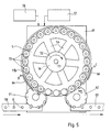
- Fig. 5 shows a schematic representation of a top view of a filling device according to the invention.
- the storage container 1 is rotatably mounted on a machine bed 49 about a vertical axis 51 in the direction of an arrow 52.
- the storage container 1 as already described in connection with the preceding figures, is designed as an annular bowl which, on its underside, carries a row of filling heads 53 in the circumferential direction next to one another, as described in the preceding Figures 1 to 4.
- the filling heads 53 are not visible per se in the top view of FIG. 5, but are indicated here by circles for better understanding.
- the ring bowl 1 is connected to a central supply space 56 surrounding the axis of rotation 51 via connections 54, which can be designed as tubes or channels.
- the reservoir is connected to a liquid reservoir 57 via a central feed line in the axis of the reservoir and corresponding rotary connections. Control means, not shown in the drawing, ensure that the liquid level in the reservoir 1 remains as constant as possible.
- a pressure source 58 which is also connected via rotary connections to a central supply line in the axis of rotation 51 of the storage container with the gas space of the storage container, serves to keep the pressure in the storage container constant at a desired value.
- the pressure source 58 contains carbon dioxide gas, so that the desired gas atmosphere in the gas space of the storage container 1 is maintained.
- the containers 8 to be filled are conveyed up on a conveyor line 59 and transferred to a feed star 61, which feeds them at the correct distance to the filling heads of the filling device passes where, as described in connection with FIGS. 1 to 4, they are docked for filling onto the centering and sealing bells 6 of the filling heads 53, where the filling process described then takes place.
- the filled containers 8 are taken over by a discharge star 62 and delivered to a discharge conveyor 63.
- the containers 8 are first biased after docking to the respective filling heads 53 when filling under counterpressure, for which purpose, according to FIG. 1, the pressure prevailing in the gas space 3 of the storage container is to be filled via the valve 29a Container 8 is created. This takes place in the peripheral section A / B of FIG. 5. A curve 64 is drawn in here for actuating the preload valve 29a, which acts accordingly on the preload valve 29a.
- the containers 8 are filled from the previously filled metering chambers, as has already been described above.
- further control cams of the type of control cams 11b and 64 are assigned to the peripheral section B / C of the storage container 1, but are not shown in the drawing.
- the containers 8 are relieved after the filling process, for which purpose the relief valve 31 is actuated with a control cam 66.
- the centering and sealing bell 6 is then lifted off the container again by means of the control cam 11b and transferred to the discharge star 62.
- the circumferential D / A cut the pre-dosing described above by filling the dosing chamber in the filling head, so that at A the new filling process can be initiated with a new container to be filled.
- control curves drawn in the drawing are only indicated schematically and are intended as exemplary embodiments. It goes without saying that the person skilled in the art will design and arrange these control curves in accordance with the requirements when implementing the invention.
- the passage valve 10 and the outlet valve 20 are actuated by moving a container part or the return gas pipe.
- this movable container part and / or the return gas pipe can be permanently installed.
- separately operable valves are provided in the liquid passage and / or in the liquid outlet.
- An example of such a valve is shown in FIG. 2 with the slide 38 which controls the passage openings 37.
Landscapes
- Filling Of Jars Or Cans And Processes For Cleaning And Sealing Jars (AREA)
- Basic Packing Technique (AREA)
- Vacuum Packaging (AREA)
Abstract
Description
Die Erfindung betrifft eine Vorrichtung zum Füllen von Behältern, insbesondere von Flaschen oder Dosen, mit einer vorgegebenen Menge einer Flüssigkeit.The invention relates to a device for filling containers, in particular bottles or cans, with a predetermined amount of a liquid.
Eine in einem Vorratskessel enthaltene Flüssigkeit wird gewöhnlich in Behälter, wie beispielsweise Dosen oder Flaschen abgefüllt, indem die Behälter nacheinander an einen Füllkopf angedockt werden, der am Vorratsbehälter angeordnet ist und ein einen Auslaß verschließendes Ventil aufweist, das zum Einfüllen der Flüssigkeit in die Behälter geöffnet wird. Die Flüssigkeit fließt aus dem Vorratsbehälter unter der Wirkung der Schwerkraft durch das geöffnete Ventil in den zu füllenden Behälter. Sollen Flüssigkeiten abgefüllt werden, die unter Druck stehen, wie zum Beispiel kohlensäurehaltige Getränke, so ist ein Füllkopf vorzusehen, der den Behälter zuerst mit dem Druck beaufschlagt, der auch auf die Flüssigkeit im Vorratsbehälter wirkt, so daß der zu füllende Behälter vorgespannt wird, bevor mit dem Einfüllen der Flüssigkeit begonnen wird. Sobald die Flüssigkeit aus dem Vorratsbehälter in den zu füllenden Behälter strömt, wird das Vorspanngas aus dem Behälter verdrängt. Vorzugsweise wird es durch eine Entlüftungsleitung in den Raum oberhalb der Flüssigkeit im Vorratsbehälter geleitet. Die Füllhöhe im Behälter wird durch die Lage des Endes der Entlüftungsleitung im oberen Teil des zu füllenden Behälters bestimmt. Da das innere Behältervolumen in der Regel nicht konstant ist, ist eine genaue Volumendosierung der Füllmenge auf diese Weise nicht möglich.A liquid contained in a storage kettle is usually filled into containers, such as cans or bottles, by successively docking the containers to a filling head which is arranged on the storage container and has an outlet closing valve which opens for filling the liquid into the containers becomes. The liquid flows from the storage container under the effect of gravity through the open valve into the container to be filled. If liquids are to be filled that are under pressure, such as carbonated beverages, a filling head must be provided, which first pressurizes the container with the pressure which also acts on the liquid in the storage container, so that the container to be filled is pre-stressed before the filling of the liquid is started. As soon as the liquid flows from the storage container into the container to be filled, the biasing gas is displaced from the container. It is preferably passed through a vent line into the space above the liquid in the storage container. The fill level in the container is determined by the position of the end of the vent line in the upper part of the container to be filled. Since the inner volume of the container is usually not constant, precise volume metering of the filling quantity is not possible in this way.
Der Erfindung liegt die Aufgabe zugrunde, eine Vorrichtung der eingangs beschriebenen Art zum Abfüllen von volumetrisch abgemessenen Mengen einer Flüssigkeit anzugeben.The invention has for its object to provide a device of the type described above for filling volumetrically measured amounts of a liquid.
Gelöst wird diese Aufgabe bei einer Vorrichtung der eingangs beschriebenen Art erfindungsgemäß durch einen die abzufüllende Flüssigkeit bereithaltenden Vorratsbehälter und eine mit dem Vorratsbehälter über einen verschließbaren Flüssigkeitsdurchlaß verbundene Dosierkammer vorgegebenen Volumens, die einen verschließbaren Flüssigkeitsauslaß und Zentrier- und Abdichtmittel zum Andocken aufeinanderfolgender zu füllender Behälter aufweist.This object is achieved according to the invention in a device of the type described at the outset by a storage container holding the liquid to be filled and a metering chamber of predetermined volume connected to the storage container via a closable liquid passage, which has a closable liquid outlet and centering and sealing means for docking successive containers to be filled.
Merkmale erfinderischer Fortführungen sowie vorteilhafter und zweckmäßiger Ausgestaltungen der Erfindung sind in den Unteransprüchen enthalten.Features of inventive continuations as well as advantageous and expedient refinements of the invention are contained in the subclaims.
Die Erfindung bietet den Vorteil, daß sie das Abfüllen genau vorgegebener Mengen einer Flüssigkeit in nacheinander anzudockende Behälter wie Dosen oder Flaschen gestattet. Die Abfüllmengen in aufeinanderfolgenden Behältern sind nicht mehr abhängig vom Innenvolumen der jeweiligen Behälter. Von besonderer und eigenständig erfinderischer Bedeutung sind die Merkmale der Ansprüche, die sich auf die Anordnung der Dosierkammer innerhalb des Vorratsbehälters beziehen. Durch diese Integrierung der Dosierkammer in den Vorratsbehälter wird nicht nur ein kompakter und raumsparender Aufbau der Füllvorrichtung erreicht, sondern es ergibt sich auch eine gerade für das Abfüllen einer in dem Vorratsbehälter unter erhöhtem Druck stehenden Flüssigkeit besonders geeignete Konzeption der Füllvorrichtung. Dabei macht der gemäß den Ansprüchen 8 und 9 in die Dosierkammer eingesetzte, von außen verstellbare Verdrängerkörper die Füllvorrichtung nach der Erfindung besonders flexibel, weil sie auf verschiedene volumenmäßig bestimmbare Füllmengen einstellbar ist. Eigenständig erfinderische Bedeutung kommt auch den Merkmalen der Ansprüche zu, die sich auf die Anordnung des Verdrängerkörpers in der Dosierkammer beziehen. Der Verdrängerkörper dient gleichzeitig als Montage- und Führungskörper für mehrere Bestandteile der erfindungsgemäß vorgeschlagenen Füllvorrichtung und macht dadurch den Füllkopf der Vorrichtung zu einer kompakten, separat montierbaren und leicht handhabbaren und justierbaren Baueinheit, die außerhalb des Vorratsbehälters montierbar und als Ganzes in den Vorratsbehälter einsetzbar ist. Ein weiterer Vorteil besteht darin, daß durch die Begrenzung des Volumens der Dosierkammer mittels eines Schwimmerventils in der Rückgasleitung die Genauigkeit der Dosierung erhöht wird. Sie wird dadurch unabhängig von der Füllhöhe der Flüssigkeit im Vorratsbehälter. Die Füllvorrichtung nach der Erfindung ist konstruktiv einfach und in ihrer Funktion sicher, weil sie nur wenige bewegte Teile aufweist. Als besonders vorteilhaft wird die Ausführung nach Anspruch 7 angesehen, weil der innere Dosierkammerteil gleichzeitig eine Ventilfunktion für den Durchlaß der Flüssigkeit zur Dosierkammer hat. Auch die Gestaltung des Rückgasrohrs als Träger und Betätigungsorgan des Aulaßventils der Dosierkammer zum jeweils angedockten Behälter hin erhöht die Einfachheit der Konstruktion der Füllvorrichtung nach der Erfindung, weil damit zusätzliche, relativ zueinander zu bewegende Teile eingespart werden. Das erhöht gleichzeitig die Funktionssicherheit der Vorrichtung. Da das Rückgasrohr zudem nicht mit dem Flüssigkeitsspiegel in dem zu füllenden Behälter in Berührung kommt, also ein kurzes Rückgasrohr vorgesehen sein kann, ist nur ein kurzer Hub der Zentrier- und Abdichtglocke bzw. der Behälter zum Andocken erforderlich, was die Taktfolge des Füllvorgangs erhöht und damit wesentlich zur höheren Wirtschaftlichkeit der Vorrichtung beiträgt. Da das Vorspannen der zu füllenden Behälter nicht durch das Rückgasrohr erfolgt, sondern durch eine separate, ventilgesteuerte Vorspannleitung, bzw. das Rückgasrohr nicht in die Flüssigkeit im gefüllten Behälter eintaucht und daher an seiner Innenwand nicht mit Flüssigkeit benetzt wird, ist die Gefahr des Aufschäumens beim Füllen der Behälter herabgesetzt, weil durch das Vorspannen keine Flüssigkeit in das Behälterinnere versprüht wird. Der Füllvorgang kann in vorteilhafter Weise beschleunigt werden, indem gemäß der Erfindung der Innendruck des Behälters beim Füllen herabgesetzt wird. Durch die abnehmende Füllgeschwindigkeit gegen Ende des Füllvorganges wird eine Beruhigung der Flüssigkeitsströmung bewirkt, was die Gefahr des Aufschäumens der Flüssigkeit im zu füllenden Behälter verringert.The invention offers the advantage that it allows the filling of precisely specified quantities of a liquid into containers such as cans or bottles to be docked one after the other. The filling quantities in successive containers are no longer dependent on the internal volume of the respective container. The features of the claims relating to the arrangement of the metering chamber within the storage container are of particular and independent inventive importance. This integration of the dosing chamber into the storage container not only achieves a compact and space-saving construction of the filling device, but also results in a conception of the filling device that is particularly suitable for filling a liquid in the storage container under increased pressure. In this case, the externally adjustable displacement body which is inserted into the metering chamber in accordance with
Die Füllkopfausführungen, bei denen die Dosierkammer von unten her aufgefüllt wird, gewährleisten ein ruhig und dennoch schnell ablaufendes Füllen der Dosierkammer ohne den Dosiervorgang wesentlich beeinträchtigende Blasen- und Wirbelbildung.The filling head versions, in which the dosing chamber is filled from below, ensure that the dosing chamber is filled smoothly and yet quickly without the formation of bubbles and vortices that significantly impair the dosing process.
Insgesamt wird durch die Erfindung in sehr vorteilhafter Weise eine Füllvorrichtung zum dosierten Abfüllen von Flüssigkeiten mit einem konstruktiv kompakten, leicht zu montierenden, zu handhabenden und zu justierenden und dabei außerordentlich funktionssicheren und schnellen Füllkopf bereitgestellt, die in besonders vorteilhafter Weise auch das Abfüllen von unter Druck stehender Flüssigkeit gestattet.Overall, the invention provides in a very advantageous manner a filling device for metered filling of liquids with a structurally compact, easy to assemble, handle and adjust and at the same time extremely functionally reliable and fast filling head, which in a particularly advantageous manner also fills under pressure standing liquid allowed.
Durch die Erfindung wird in vorteilhafter Weise ein äußerst schnelles Füllventil bereitgestellt, das bei hoher Funktionssicherheit hohe Abfüllgeschwindigkeiten exakt dosierter Füllmengen erlaubt.The invention advantageously provides an extremely fast filling valve which, with high functional reliability, allows high filling speeds of precisely metered filling quantities.
Die Erfindung wird nun anhand der Zeichnung näher erläutert. Es zeigen:
- Fig. 1 ein Ausführungsbeispiel der Erfindung in einem
- Längsschnitt,
- Fig. 2 ein anderes Ausführungsbeispiel der Erfindung, ebenfalls in einem Längsschnitt,
- Fig. 3 ein weiteres Ausführungsbeispiel der Erfindung in einem Längsschnitt,
- Fig. 4 einen Längsschnitt durch ein viertes Ausführungsbeispiel der Erfindung und
- Fig. 5 eine schematische Darstellung einer Draufsicht auf eine Füllvorrichtung nach der Erfindung.
- Fig. 1 shows an embodiment of the invention in one
- Longitudinal section,
- 2 shows another embodiment of the invention, also in a longitudinal section,
- 3 shows a further embodiment of the invention in a longitudinal section,
- Fig. 4 shows a longitudinal section through a fourth embodiment of the invention and
- Fig. 5 is a schematic representation of a plan view of a filling device according to the invention.
Die in Fig. 1 dargestellte Füllvorrichtung weist einen Vorratsbehälter 1 auf, der in bekannter Weise als um eine vertikale Achse umlaufender Ringkessel ausgebildet sein kann (vgl.Fig .5) In dem Ringkessel ist eine abzufüllende Flüssigkeit 2 enthalten. Das Flüssigkeitsniveau wird mit bekannten, in der Zeichnung nicht dargestellten Mitteln konstantgehalten. Oberhalb des Flüssigkeitsniveaus befindet sich ein Gasraum 3, der ein unter einem erhöhten Druck stehendes Gas enthält. An der Unterseite des Vorratsbehälters 1 ist ein topfförmiger Behälteransatz 4 angebracht, dessen Außenseite als Führung für eine Zentrierund Abdichtglocke 6 ausgebildet ist. Die Zentrier- und Abdichtglocke 6 weist an ihrem unteren Auslaß eine Dichtung 7 auf, mit der sie auf einen zu füllenden Behälter 8, beispielsweise eine Dose oder Flasche, gedrückt wird. Aufeinanderfolgende Behälter 8 werden mittels eines Trägers 9 während des Füllvorganges gehalten. Die Zentrier- und Abdichtglocke 6 ist am Behälteransatz 4 auf- und abbewegbar. Dazu weist sie im dargestellten Ausführungsbeispiel eine Steuerrolle 11 auf, die mittels einer Steuerkurve 11b in Richtung eines Doppelpfeiles 11a auf und ab geführt wird und dadurch die Zentrier- und Abdichtglocke 6 entsprechend bewegt.The filling device shown in FIG. 1 has a
Das Innere des Behälteransatzes 4 stellt den unteren Teil einer Dosierkammer 12 dar, dessen oberer Teil von einem Hohlzylinder 13 gebildet wird, der zum Behälteransatz 4 axial fluchtend im Innern des Vorratsbehälters 1 angeordnet ist. Der Hohlzylinder 13 liegt mit seinem unteren Ende um den inneren Zugang zum Behälteransatz 4 herum am Boden des Vorratsbehälters 1 an und dichtet mittels einer Dichtung 13a die Dosierkammer 12 zur Flüssigkeit 2 hin ab. Der Hohlzylinder 13 ist in Richtung eines Pfeiles 13b axial bewegbar, wozu ein mittels einer Steuerkurve 15a und einer Steuerrolle 15b betätigter Exzenter 15 vorgesehen ist, der in einen entsprechenden Mitnehmer 13c des Hohlzylin ders 13 eingreift. Am unteren Ende des Hohlzylinders 13 ist eine in den Behälteransatz 4 hineinragende zylindrische Leitfläche 14 angeordnet, die die Strömung der aus dem Vorratsbehälter 1 in die Dosierkammer 12 fließenden Flüssigkeit vergleichmäßigen soll.The inside of the container neck 4 represents the lower part of a
In den Hohlzylinder 13 ist von oben ein Verdrängerkörper 16 eingesetzt, der mit einer Führungsstange 16a im Gehäuse des Vorratsbehälters 1 gelagert und in Richtung eines Pfeiles 16b von außen einstellbar ist. Die axiale Lage des Verdrängerkörpers 16 in dem Hohlzylinder 13 bestimmt das Füllvolumen der Dosierkammer 12.A
Der Verdrängerkörper 16 bildet gleichzeitig die Axialführung des Hohlzylinders 13 in Richtung des Doppelpfeiles 13b.The
Durch den Verdrängerkörper 16 verläuft eine Rückgasleitung 17 zwischen der Dosierkammer 12 und dem Gasraum 3 des Vorratsbehälters. Diese Rückgasleitung 17 weist ein Schwimmerventil 18 mit einer Schwimmerkugel 18a auf, das die Füllhöhe der Dosierkammer unterhalb des Flüssigkeitsspiegels im Vorratsbehälter 1 begrenzt. Eine Rückgasleitung 19 ist auch zwischen der Außenseite der zylindrischen Leitfläche 14 und der Innenwand des Behälteransatzes 4 vorgesehen.A
Im Verdrängerkörper 16 ist außerdem ein Rückgasrohr 21 in Richtung eines Pfeiles 21a bewegbar geführt. Zum Betätigen dieses Rückgasrohres ist ein Exzenter 25 vorgesehen, der mittels einer Kurve 25a und einer Steuerrolle 25b bewegt wird und mit Mitnehmern 21b zusammenwirkt. Dieses Rückgasrohr 21 verbindet das Innere eines zum Füllen angedockten Behälters 8 mit dem Gasraum 3 des Vorratsbehälters 1. Im Bereich des unteren Auslasses der Dosierkammer 12 ist es als Ventil 22 mit einer Dichtung 22a ausgebildet, das den Auslaß der Dosierkammer zum Behälter hin verschließt. Im Innern des Rückgasrohres 21 ist ein Kugelrückschlagventil 23 angeordnet, welches den Gasraum 3 des Vorratsbehälters 1 gegen Atmosphäre oder niedrigeren Druck, als er im Gasraum herrscht, verschließt. Das obere Ende des Rückgasrohres 21 korrespondiert mit einem Rückgasanschluß 24, der über ein Wechselventil 26 wahlweise mit dem Gasraum 3 des Vorratsbehälters 1 oder einem zusätzlichen Gasraum 27 in Verbindung steht, welcher ein Gas unter einem gegenüber dem Gasraum 3 verminderten Druck enthält. Der Gasraum 27 bildet mit dem Vorratsbehälter 1 eine bauliche Einheit und kann ebenfalls als Ringraum ausgebildet sein. Das Wechselventil 26 ist über ein Stellorgan 28 in Richtung eines Pfeiles 28averstellbar.In the
Für den Fall, daß eine unter einem erhöhten Druck stehende Flüssigkeit 2 abgefüllt werden soll, ist eine Vorspannleitung 29 vorgesehen, die über ein Ventil 29a den Gasraum des Vorratsbehälters 1 mit dem Innern der Zentrier- und Abdichtglocke 6 und dem Innern eines angedockten Behälters 8 verbindet. Die Anordnung der Vorspannleitung ist im Bereich der Zentrier- und Abdichtglocke 6 so getroffen, daß zwischen einem Ringraum 6a in der Zentrier- und Abdichtglocke 6 und dem Behälterinneren ein Differenzdruck entsteht, der das Anpressen der Dichtung 7 gegen den oberen Rand des zu füllenden Behälters verstärkt.In the event that a
Ein Entlastungsventil 31 dient zum Entspannen des Behälters 8 nach dem Füllen mit einer unter einem erhöhten Druck stehenden Flüssigkeit.A
Es sei angenommen, daß der Vorratsbehälter 1 ein kohlensäurehaltiges Getränk 2 enthält und daß das Gas im Gasraum 3 oberhalb des Flüssigkeitsspiegels unter einem erhöhten Druck steht. Der Druck im zusätzlichen Gasraum 27 liegt unterhalb des Drucks im Gasraum 3. Zum Abfüllen einer solchen Flüssigkeit wird etwa folgendermaßen vorgegangen:It is assumed that the
Der Hohlzylinder 13 liegt über die Dichtung 13a am Boden des Vorratsbehälters 1 an und verschließt die Dosierkammer gegen die Flüssigkeit 2. Der Flüssigkeitsauslaß 20 der Dosierkammer 12 zum Behälter 8 hin ist durch das Ventil 22 geschlossen. Ein Behälter 8 wird unter der Zentrier- und Abdichtglocke 6 positioniert, und die Zentrier- und Abdichtglocke wird mittels der Steuerrolle 11 und der Steuerkurve 11b auf den oberen Rand des Behälters 8 abgesenkt. Dann wird durch Öffnen des Vorspannventils 29a der Druck des Gases im Gasraum 3 an das Innere des Behälters 8 gelegt, so daß der Behälter 8 vorgespannt wird, wobei der Differenzdruck zwischen dem Ringraum 6a in der Zentrier- und Abdichtglocke 6 und dem Inneren des Behälters 8 die Anpressung der Dichtung 7 an den oberen Behälterrand verstärkt. Bei geschlossenem Ventil 22 wird dann der Hohlzylinder 13 in Richtung des Pfeiles 13b angehoben, so daß der Flüssigkeitsdurchlaß 10 zwischen dem Vorratsbehälter 1 und der Dosierkammer geöffnet wird und die Flüssigkeit in die Dosierkammer fließt, wobei die Strömung der Flüssigkeit durch die zylindrische Leitfläche 14 beruhigt wird, so daß ein Aufschäumen unterdrückt wird. Das in der Dosierkammer 12 enthaltene Gas entweicht beim Einströmen der Flüssigkeit durch die Rückgasleitung 17, bis das in der Dosierkammer erreichte Flüssigkeitsniveau die Schwimmerkugel 18a anhebt und das Schwimmerventil 18 schließt. Durch Absenken des Hohlzylinders 13 in Richtung des Pfeiles 13b wird der Flüssigkeitsdurchlaß 10 zwischen dem Vorratsbehälter 1 und der Dosierkammer jetzt geschlossen. Die Dosierkammer enthält eine exakt abgemessene Menge der abzufüllenden Flüssigkeit. Die in der Dosierkammer enthaltene Flüssigkeitsmenge ist durch ihr Volumen bestimmt, das mit Hilfe des Verdrängerkörpers 16 eingestellt wird. Durch axiales Verschieben des Verdrängerkörpers 16 in Richtung des Pfeiles 16b wird das gewünschte Volumen der Dosierkammer jeweils voreingestellt.The
Nach dem Füllen der Dosierkammer wird durch Anheben des Rückgasrohres 21 das Ventil 22 am Flüssigkeitsauslaß 20 der Dosierkammer zum Behälter 8 hin geöffnet, nachdem das Ventil 29a der Vorspannleitung geschlossen worden ist. Gleichzeitig wird das obere Ende des Rückgasrohres an den Rückgasanschluß 24 angelegt. Das Ventil 26 ist zunächst so eingestellt, daß über das Rückgasrohr, den Rückgasanschluß 24 und das Ventil 26 zunächst eine Verbindung zwischen dem Innern des Behälters 8 und dem Gasraum 3 des Vorratsbehälters 1 besteht, so daß das beim Ausströmen der Flüssigkeit aus der Dosierkammer in den Behälter 8 verdrängte Gas zunächst in den Gasraum 3 geführt wird. Um den Füllvorgang zu beschleunigen, kann zu einem vorgegebenen Zeitpunkt das Ventil 26 mittels des Stellorgans 28 umgeschaltet werden, so daß da's Behälterinnere mit dem Gasraum 27 verminderten Drucks verbunden wird. Es entsteht eine Art Saugeffekt, welcher das Füllen des Behälters 8 beschleunigt und somit höhere Taktzeiten erlaubt.After the metering chamber has been filled, by lifting the
Das untere Ende des Rückgasrohres 21 kommt mit der in den Behälter 8 abgefüllten Flüssigkeit nicht mehr in Berührung. Dadurch sind zum Andocken des Behälters 8 nur kurze Hübe erforderlich, was die Taktzeit des Abfüllvorgangs erhöht und die Wirtschaftlichkeit der Vorrichtung verbessert.The lower end of the
Sobald der Inhalt der Dosierkammer in den Behälter 8 umgefüllt ist, wird das Ventil 22 durch Absenken des Rückgasrohres in Richtung des Pfeiles 21a geschlossen. Zum Entlasten des Behälters 8 wird dann das Entlastungsventil 31 geöffnet, wodurch der Behälter an Atmosphärendruck gelegt wird. Dabei verschließt das Kugelrückschlagventil 23 das Rückgasrohr 21 und verhindert ein Aus strömen des Gases aus dem Gasraum 3 des Vorratsbehälters 1. Nach Anheben der Zentrier- und Abdichtglocke 6 durch die von der Steuerkurve 11b geführte Steuerrolle 11 vom oberen Rand des Behälters 8 und der Abnahme des Behälters von der Auslaßöffnung der Dosierkammer 12 kann ein neuer zu füllender Behälter angedockt werden und der Füllvorgang erneut beginnen.As soon as the contents of the metering chamber have been poured into the
Die Mittel zum Bewegen des Rückgasrohres 21 in Richtung des Pfeiles 21a und des Hohlzylinders 13 in Richtung des Pfeiles 13b sind an sich bekannt und bedürfen hier keiner näheren Beschreibung. Hierzu wird auf Fig. 5 verwiesen.The means for moving the
Die Füllvorrichtung nach Fig. 2 unterscheidet sich von der nach Fig. 1 durch eine andere Ausbildung der Dosierkammer und durch den Fortfall des zusätzlichen Gasraumes. Gleiche Teile sind in Fig. 2 mit denselben Bezugszeichen versehen wie in Fig. 12 differs from that of FIG. 1 by a different design of the metering chamber and by the elimination of the additional gas space. The same parts are given the same reference numerals in FIG. 2 as in FIG. 1
Im Falle der Fig. 2 ist eine Dosierkammer 32 vorgesehen, welche einstückig als etwa zylindrisches Bauteil ausgebildet ist. Sie ist von unten in den Vorratsbehälter 3 eingesetzt und mittels eines Flansches 33 an seiner Unterseite befestigt. Ein innerhalb des Vorratsbehälters 1 liegender Teil 34 der Dosierkammer ragt durch die Flüssigkeit 2 bis in den Gasraum 3. In diesen Teil 34 der Dosierkammer ist der Verdrängerkörper 16 eingesetzt, der zum Einstellen des Volumens der Dosierkammer in Richtung des Pfeiles 16b axial verschiebbar ist, die Rückgasleitung 17 mit dem Schwimmerventil 18 enthält und als Führung für das Rückgasrohr 21 dient. Außerhalb des Vorratsbehälters 1 liegt an dessen Unterseite der untere Dosierkammerteil 36, dessen Äußeres wie im Fall der Fig. 1 als Führung für die Zentrier- und Abdichtglocke 6 ausgebildet ist. Im Bereich des Bodens des Vorratsbehälters (1 sind rings am Umfang des inneren Dosierkammerteils 32 Flüssigkeitsdurchlässe 37 vorgesehen, die mit einem die Dosier kammer umgebenden, im wesentlichen zylindrisch ausgebildeten Schieber 38 verschließbar sind.In the case of FIG. 2, a
Der Füllvorgang mit dieser Ausführungsform der Füllvorrichtung ist derselbe wie im Zusammenhang mit der Ausführungsform der Fig. 1 beschrieben. Beim Füllen der Behälter 8 mit diesem Füllkopf ist es lediglich ausgeschlossen, den Füllvorgang durch Anlegen eines verminderten Drucks an das Behälterinnere zu beschleunigen. Diese Möglichkeit kann aber durch eine der Fig .1 entsprechende Ausbildung mit zusätzlichem Gasraum ebenfalls installiert werden. Die Ausführungsform der Fig. 2 hat den Vorteil, daß der Füllkopf, bestehend aus der Dosierkammer und der Zentrier- und Abdichtglocke, in einem Stück vormontiert und dann in den Vorratsbehälter eingesetzt werden kann.The filling process with this embodiment of the filling device is the same as described in connection with the embodiment of FIG. 1. When filling the
In Fig. 3 ist eine weitere Variante der Füllvorrichtung nach der Erfindung in einem Längsschnitt schematisch dargestellt, wobei gleiche Teile wieder mit denselben Bezugszeichen bezeichnet sind wie zuvor. Bei dieser Ausführungsform ist in den Vorratsbehälter 1, der an seiner Unterseite einen mit dem Flüssigkeitsraum des Vorratsbehälters in Verbindung stehenden Behälteransatz 4a aufweist, eine Dosierkammer 12 eingesetzt, die als ein im wesentlichen zylindrischer Hohlkörper 39 ausgebildet ist und dicht auf dem Boden des Vorratsbehälters im Behälteransatz 4a aufsitzt. In ihrem Anlagebereich, mit dem die Dosierkammer den Behälterboden berührt, ist sie mit einer Dichtung 39a versehen, die den Flüssigkeitsraum 2 des Vorratsbehälters zur Dosierkammer hin abdichtet. Der Hohlkörper 39 ist im Vorratsbehälter 1 in Halterungen 41 in Richtung eines Pfeiles 39a vertikal beweglich geführt. Wird der Hohlkörper 39 in Richtung des Pfeiles 39b vom Boden des Behälteransatzes 4a abgehoben, so öffnet sich ein Flüssigkeitsdurchlaß 10, durch den die Flüssigkeit 2 aus dem Vorratsbehälter von unten in die Dosierkammer 12 einströmt. Der Flüssigkeitsauslaß 20 zum zu füllenden Behälter 8 hin im Boden der Dosierkammer ist bei diesem Vorgang geschlossen. Der Hohlkörper 39 füllt sich nach dem Prinzip der kommunizierenden Röhren bis zum Niveau der Flüssigkeit im Vorratsbehälter. Das Volumen der Dosierkammer 12 wird durch die Eintauchtiefe des Verdrängerkörpers 16 bestimmt, die von außen mittels eines Einstellmittels 42 vorgegeben werden kann. Das in der Dosierkammer enthaltene Gas entweicht beim Füllen der Dosierkammer an dem Verdrängerkörper 16 vorbei und durch ihn hindurch nach oben in den Gasraum 3 des Vorratsbehälters.In Fig. 3, a further variant of the filling device according to the invention is shown schematically in a longitudinal section, wherein the same parts are again designated with the same reference numerals as before. In this embodiment, a
Sobald der Vorratsbehälter gefüllt ist, wird der Hohlkörper 39 auf den Boden des Vorratsbehälters abgesenkt und der Flüssigkeitsdurchlaß 10 damit geschlossen. Jetzt wird zum Vorspannen des Behälters 8 das das Rückgasrohr 21 zum Gasraum 3 hin verschließende Ventil 43 geöffnet. Nach dem Vorspannen wird das Rückgasrohr in Richtung des Doppelpfeiles 21a nach oben bewegt, wodurch der Flüssigkeitsauslaß 20 zum Behälter 8 hin geöffnet wird und die volumetrisch abgemessene Flüssigkeitsmenge in der Dosierkammer in den Behälter 8 abgegeben wird. Dabei entweicht das in dem Behälter 8 enthaltene Gas durch das Rückgasrohr 21 in den Gasraum 3. Nach dem Umfüllen des Inhalts der Dosierkammer in den Behälter 8 werden der Flüssigkeitsauslaß 20 und das Ventil 43 wieder geschlossen und es kann ein neuer Füllvorgang beginnen. Diese Ausbildung und Anordnung der Dosierkammer 12 hat den Vorteil, daß die Flüssigkeit 2 aus dem Vorratsbehälter von unten in der Dosierkammer hoch steigen kann, was eine Wirbelbildung und damit verbundenes Aufschäumen der Flüssigkeit weitgehend verhindert.As soon as the storage container is filled, the
Auch im Falle der Fig. 3 kann der Vorratsbehälter 1 als Ringkammer ausgebildet sein, welche rings an ihrem Umfang nebeneinander eine ganze Reihe der beschriebenen Vorrichtungen trägt, um ein kontinuierliches Füllen aufeinanderfolgender Behälter 8 zu ermöglichen.In the case of FIG. 3 too, the
Fig. 4 zeigt noch eine weitere Ausführungsform der Vorrichtung nach der Erfindung in einem schematischen Längsschnitt, wobei wieder gleiche Teile mit denselben Bezugszeichen versehen sind wie zuvor.Fig. 4 shows yet another embodiment of the device according to the invention in a schematic longitudinal section, wherein again the same parts are provided with the same reference numerals as before.
In dem in Fig. 4 dargestellten Ausführungsbeispiel ist die Dosierkammer 12 an der Unterseite des Vorratsbehälters 1 angebracht, wobei der Vorratsbehälter 1 als Ringkessel ausgebildet sein kann, an dem in Umfangsrichtung nebeneinander eine Anzahl von Dosierkammern 12 vorgesehen sind. Die Dosierkammer 12 ist als zylindrischer Hohlkörper 44 ausgebildet, der im gezeigten Beispiel an die Unterseite des Vorratsbehälters 1 angeflanscht ist. Er trägt zum Andocken von nicht gezeigten zu füllenden Behältern eine Zentrier- und Abdichtglocke 6. Im Innern des Hohlkörpers 44 ist ein Behälteransatz 46 in Form eines zylindrischen Rohrstücks angeordnet, das über sein oberes Ende mit der Flüssigkeit im Vorratsbehälter 1 in Verbindung steht und daher dauernd mit Flüssigkeit gefüllt ist. Den oberen Abschluß der Dosierkammer 12 bildet ein Verdrängerkörper 16, der die Dosierkammer zur Flüssigkeit 2 im Vorratsbehälter 1 hin dicht abschließt. Der Behälteransatz 46 ist in dem Verdrängerkörper 16 axial verschiebbar gelagert und geführt. Längsaxial durch den Behälteransatz 46 hindurchgeführt ist das Rückgasrohr 21, das das Innere eines angedockten Behälters mit dem Gasraum 3 des Vorratsbehälters 1 verbindet. Das Rückgasrohr 21 trägt im Bereich seines unteren Endes einen Ventilkörper 47, der eine doppelte Funktion erfüllt. Einerseits schließt dieser Ventilkörper 47 den Flüssigkeitsauslaß 20 der Dosierkammer 12 zum zu füllenden Behälter hin ab. Andererseits bildet dieser Ventilkörper 47 den Boden des Vorratsbehälters 1 im Bereich des Behälteransatzes 46. Der Behälteransatz 46 liegt dicht auf dem Ventilkörper 47 auf.In the exemplary embodiment shown in FIG. 4, the
Wird bei geschlossenem Flüssigkeitsauslaß 20 der Behälteransatz 46 angehoben, so öffnet sich der Flüssigkeitsdurchlaß 10 und die Flüssigkeit 2 strömt aus dem Vorratsbehälter 1 durch den Behälteransatz 46 in die Dosierkammer 12, die das den Behälteransatz 46 bildende Rohrstück konzentrisch umgibt, wobei das in der Dosierkammer enthaltene Gas durch eine Gasleitung 48 in den Gasraum 3 des Vorratsbehälters entweicht. Das Volumen der Dosierkammer 12 wird durch Verschieben des Verdrängerkörpers 16 von außen mittels der Rückgasleitung 40 nach Wunsch eingestellt. Sobald die Dosierkammer 12 gefüllt ist, wird der Behälteransatz 46 auf den Ventilkörper 47 abgesenkt, so daß der Flüssigkeitsdurchlaß 10 geschlossen wird. Nach dem Vorspannen des zu füllenden Behälters durch das Rückgasrohr 21 hindurch wird das Rückgasrohr zusammen mit dem Ventilkörper 47 und dem Behältersansatz 46 nach oben bewegt, wodurch der Flüssigkeitsauslaß 20 zum Füllen des Behälters geöffnet wird. Der Flüssigkeitsdurchlaß 10 bleibt dabei geschlossen. Das aus dem zu füllenden Behälter während des Füllvorganges verdrängte Gas gelangt durch das Rückgasrohr 21 in den Gasraum des Vorratsbehälters 1. Nach dem Füllen des Behälters wird das Rückgasrohr 21 zusammen mit dem Behälteransatz 46 abgesenkt, um den Flüssigkeitsauslaß 20 wieder zu schließen. Auch diese Vorrichtung hat den Vorteil, daß die Dosierkammer von unten her mit der Flüssigkeit gefüllt wird, wobei ein Aufsprudeln der Flüssigkeit vermieden ist.If the container neck 46 is raised when the
In allen gezeigten Ausführungsbeispielen sind die Betätigungsmittel zum Einstellen des Füllvolumens der Dosierkammer 12 durch Höhenverstellung der Verdrängerkörper 16 nach oben aus dem Vorratsbehälter herausgeführt. Dadurch wird es möglich, sie mit einer Steuerung zu verbinden, die es erlaubt, dieIn all of the exemplary embodiments shown, the actuating means for adjusting the filling volume of the
Verdrängerkörper je nach den Anforderungen des Betriebes einzeln oder gemeinsam zentral einzustellen.Depending on the requirements of the company, displacement bodies can be adjusted individually or together centrally.
Fig. 5 zeigt in schematischer Darstellung eine Draufsicht auf eine Füllvorrichtung nach der Erfindung. Auf einem Maschinenbett 49 ist der Vorratsbehälter 1 um eine vertikale Achse 51 in Richtung eines Pfeiles 52 drehbar gelagert. Der Vorratsbehälter 1 ist, wie im Zusammenhang mit den vorangehenden Figuren bereits beschrieben, als Ringkessel ausgebildet, der an seiner Unterseite in Umfangsrichtung nebeneinander eine Reihe von Füllköpfen 53 derart trägt, wie sie in den vorangehenden Figuren 1 bis 4 beschrieben sind. Die Füllköpfe 53 sind in der Draufsicht der Fig. 5 an sich nicht sichtbar, hier aber der besseren Verständlichkeit wegen durch Kreise angedeutet. Über Verbindungen 54, die als Röhren oder Kanäle ausgebildet sein können, ist der Ringkessel 1 mit einem die Drehachse 51 umgebenden zentralen Versorgungsraum 56 verbunden. Über eine zentrale Zuführleitung in der Achse des Vorratsbehälters und entsprechende Drehanschlüsse ist der Vorratsbehälter an einen Flüssigkeitsvorrat 57 angeschlossen. In der Zeichnung nicht gezeigte Steuermittel sorgen dafür, daß der Flüssigkeitsspiegel im Vorratsbehälter 1 möglichst konstant bleibt. Eine Druckquelle 58, die ebenfalls über Drehanschlüsse mit einer zentralen Versorgungsleitung in der Drehachse 51 des Vorratsbehälters mit dem Gasraum des Vorratsbehälters verbunden ist, dient dazu, den Druck im Vorratsbehälter auf einem gewünschten Wert konstant zu halten. Beim Abfüllen CO₂-haltiger Getränke enthält die Druckquelle 58 Kohlendioxydgas, so daß die gewünschte Gasatmosphäre im Gasraum des Vorratsbehälters 1 aufrechterhalten wird.Fig. 5 shows a schematic representation of a top view of a filling device according to the invention. The
Die zu füllenden Behälter 8 werden auf einer Förderstrecke 59 herangefördert und an einen Zuführstern 61 übergeben, der sie im richtigen Abstand an die Füllköpfe der Füllvorrichtung übergibt, wo sie, wie im Zusammenhang mit den Figuren 1 bis 4 beschrieben, zum Füllen an die Zentrier- und Abdichtglocken 6 der Füllköpfe 53 angedockt werden, wo dann der beschriebene Füllvorgang abläuft. Die gefüllten Behälter 8 werden von einem Abförderstern 62 übernommen und an einen Abförderer 63 abgegeben.The
Wie im Zusammenhang mit der Fig. 1 beschrieben, erfolgt das Absenken der Zentrier- und Abdichtglocken 6 der Füllköpfe 53 und das Anheben kurvengesteuert. Die dazu vorgesehene Kurvenführung 1lb ist in Fig. 5 rings um den Vorratsbehälter herum verlaufend eingezeichnet.As described in connection with FIG. 1, the centering and sealing bells 6 of the filling heads 53 are lowered and the cam-controlled lifting takes place. The
Wie im Zusammenhang mit den vorangehenden Figuren schon beschrieben, werden die Behälter 8 nach dem Andocken an die jeweiligen Füllköpfe 53 beim Füllen unter Gegendruck zunächst vorgespannt, wozu gemäß Fig. 1 über das Ventil 29a der im Gasraum 3 des Vorratsbehälters herrschende Druck an den zu füllenden Behälter 8 angelegt wird. Dies erfolgt in dem Umfangsabschnitt A/B der Fig. 5. Zum Betätigen des Vorspannventils 29a ist hier eine Kurve 64 eingezeichnet, die entsprechend auf das Vorspannventil 29a einwirkt.As already described in connection with the preceding figures, the
In dem Umfangsabschnitt B/C der Fig. 5 erfolgt das Füllen der Behälter 8 aus den vorher gefüllten Dosierkammern, wie es oben schon beschrieben wurde. Hierzu sind dem Umfangsabschnitt B/C des Vorratsbehälters 1 weitere Steuerkurven in der Art der Steuerkurven 11b und 64 zugeordnet, die aber in der Zeichnung nicht dargestellt sind. Im Umfangsabschnitt G/D werden die Behälter 8 nach dem Füllvorgang entlastet, wozu mit einer Steuerkurve 66 das Entlastungsventil 31 betätigt wird. Danach wird die Zentrier- und Abdichtglocke 6 mittels der Steuerkurve 11b wieder von dem Behälter abgehoben und dieser an den Abförderstern 62 übergeben. Inzwischen erfolgt in dem Umfangsab schnitt D/A die oben beschriebene Vordosierung durch Füllen der Dosierkammer im Füllkopf, so daß bei A der neue Füllvorgang mit einem neuen zu füllenden Behälter eingeleitet werden kann.In the peripheral section B / C of FIG. 5, the
Die in der Zeichnung eingezeichneten Steuerkurven sind nur schematisch angedeutet und als Ausführungsbeispiele gedacht. Es ist selbstverständlich, daß der Fachmann diese Steuerkurven bei der Realisierung der Erfindung entsprechend den Erfordernissen ausgestalten und anordnen wird.The control curves drawn in the drawing are only indicated schematically and are intended as exemplary embodiments. It goes without saying that the person skilled in the art will design and arrange these control curves in accordance with the requirements when implementing the invention.
Bei den in den Figuren 3 und 4 dargestellten Ausführungsbeispielen werden das Durchlaßventil 10 und das Auslaßventil 20 durch Bewegen eines Behälterteiles bzw. des Rückgasrohres betätigt. Natürlich können dieser beweglich dargestellte Behälterteil und/oder das Rückgasrohr fest installiert sein. In diesem Fall sind im Flüssigkeitsdurchlaß und/oder im Flüssigkeitsauslaß separat betätigbare Ventile vorgesehen. Ein Beispiel für ein solches Ventil zeigt die Fig. 2 mit dem Schieber 38, der die Durchlaßöffnungen 37 steuert. Daneben gibt es viele andere Möglichkeiten der Ventilanordnung, die hier nicht dargestellt zu werden brauchen. Wichtig ist bei den Ausführungsformen der Figuren 3 und 4 vor allem die Anordnung der Dosierkammer mit dem bis zum Boden der Dosierkammer reichenden Ansatz des Vorratsbehälters, welche die oben beschriebenen Vorteile erbringt.In the exemplary embodiments shown in FIGS. 3 and 4, the
Claims (26)
Applications Claiming Priority (2)
| Application Number | Priority Date | Filing Date | Title |
|---|---|---|---|
| DE3928009 | 1989-08-24 | ||
| DE3928009A DE3928009A1 (en) | 1989-08-24 | 1989-08-24 | DEVICE FOR FILLING CONTAINERS |
Publications (2)
| Publication Number | Publication Date |
|---|---|
| EP0414075A1 true EP0414075A1 (en) | 1991-02-27 |
| EP0414075B1 EP0414075B1 (en) | 1993-11-18 |
Family
ID=6387806
Family Applications (1)
| Application Number | Title | Priority Date | Filing Date |
|---|---|---|---|
| EP90115441A Expired - Lifetime EP0414075B1 (en) | 1989-08-24 | 1990-08-11 | Device for filling containers |
Country Status (6)
| Country | Link |
|---|---|
| US (1) | US5125440A (en) |
| EP (1) | EP0414075B1 (en) |
| JP (1) | JPH03240607A (en) |
| CA (1) | CA2023914A1 (en) |
| DE (2) | DE3928009A1 (en) |
| ES (1) | ES2046622T3 (en) |
Cited By (5)
| Publication number | Priority date | Publication date | Assignee | Title |
|---|---|---|---|---|
| DE4312367A1 (en) * | 1993-04-16 | 1994-10-20 | Kronseder Maschf Krones | Device for the dispensing of liquids into bottles, cans or similar containers |
| DE19631971A1 (en) * | 1996-08-08 | 1998-02-12 | Ischwang Stefan Amadeus | Filling appliance for liquid products |
| US5865225A (en) * | 1993-04-16 | 1999-02-02 | Krones Ag Hermann Kronseder Maschinenfabrik | Rotating device for filling liquids in portions into bottles, cans or similar receptacles |
| DE19749738A1 (en) * | 1997-11-11 | 1999-05-20 | Mette Manfred | Filling element for volumetric beverage filling |
| EP3274260B1 (en) * | 2015-03-23 | 2019-08-07 | Hema | Volumetric metering device for container filling machine |
Families Citing this family (20)
| Publication number | Priority date | Publication date | Assignee | Title |
|---|---|---|---|---|
| DE4023998A1 (en) * | 1990-07-28 | 1992-01-30 | Alfill Getraenketechnik | METHOD AND DEVICE FOR FILLING A LIQUID IN PORTION CONTAINERS |
| US5234038A (en) * | 1991-09-27 | 1993-08-10 | Briggs & Stratton Corporation | Pour spout |
| US5628352A (en) * | 1992-07-24 | 1997-05-13 | Briggs & Stratton Corporation | Closable pour spout for fluid dispensing container |
| DE4303524C1 (en) * | 1993-02-06 | 1994-03-17 | Holstein & Kappert Maschf | Valve for filling bottles etc. under pressure, especially drinks - has spring which moves gas pipe downwards while valve remains closed, and cam acting on second spring then causes valve to open |
| US5848515A (en) * | 1995-08-11 | 1998-12-15 | Rossi & Catelli S.P.A. | Continuous-cycle sterile bottling plant |
| US6131624A (en) * | 1999-01-19 | 2000-10-17 | Crown Simplimatic Incorporated | Filling valve assembly |
| WO2000046103A2 (en) * | 1999-02-02 | 2000-08-10 | Milena Stagni | Method and machine for metering liquid products |
| US6449970B1 (en) | 1999-11-10 | 2002-09-17 | Shurflo Pump Manufacturing Company, Inc. | Refrigeration apparatus and method for a fluid dispensing device |
| US6360556B1 (en) | 1999-11-10 | 2002-03-26 | Shurflo Pump Manufacturing Company, Inc. | Apparatus and method for controlling fluid delivery temperature in a dispensing apparatus |
| US6443335B1 (en) | 1999-11-10 | 2002-09-03 | Shurflo Pump Manufacturing Company, Inc. | Rapid comestible fluid dispensing apparatus and method employing a diffuser |
| US6354342B1 (en) | 1999-11-10 | 2002-03-12 | Shurflo Pump Manufacturing Company, Inc. | Hand-held rapid dispensing apparatus and method |
| US6354341B1 (en) | 1999-11-10 | 2002-03-12 | Shurflo Pump Manufacturing Co., Inc. | Rapid comestible fluid dispensing apparatus and method |
| US20040232173A1 (en) * | 1999-11-10 | 2004-11-25 | Michael Saveliev | Rapid comestible fluid dispensing apparatus and method |
| US6662828B1 (en) * | 2001-05-22 | 2003-12-16 | Clifford W. Stover | Telescoping filling head |
| US6837282B2 (en) * | 2002-07-29 | 2005-01-04 | Ramon Navarro | Apparatus for filling containers with viscous liquid food products |
| DE20319789U1 (en) | 2003-12-20 | 2004-02-26 | Khs Maschinen- Und Anlagenbau Ag | Filling machine with separate return gas duct |
| JP4519146B2 (en) * | 2006-01-27 | 2010-08-04 | 株式会社トパック | Filling and packaging apparatus and filling and packaging method |
| ITPD20120028A1 (en) | 2012-02-07 | 2013-08-08 | Mbf Spa | FILLING MACHINE OF CONTAINERS WITH LIQUIDS, AND FILLING PROCEDURE OF CONTAINERS, IN PARTICULAR THROUGH THE FILLING MACHINE |
| DE102015116532A1 (en) * | 2015-09-30 | 2017-03-30 | Khs Gmbh | Method and treatment station and treatment head for treating the interiors of KEGs and seal for use in such a treatment station |
| US10479668B2 (en) * | 2016-11-08 | 2019-11-19 | Pepsico, Inc. | Ambient filling system and method |
Citations (5)
| Publication number | Priority date | Publication date | Assignee | Title |
|---|---|---|---|---|
| US2162404A (en) * | 1936-11-18 | 1939-06-13 | Fmc Corp | Filling valve |
| US3334668A (en) * | 1965-08-30 | 1967-08-08 | Ex Cell O Corp | Filler for charging containers |
| DE1807542A1 (en) * | 1968-11-07 | 1970-06-11 | Bosch Gmbh Robert | Device for measuring and filling liquids |
| FR2476626A1 (en) * | 1980-02-25 | 1981-08-28 | Seitz Werke Gmbh | Vessel filling machine with metered quantities - has displacement body in measuring cylinder adjusted by mechanism on cover |
| FR2516495A1 (en) * | 1981-11-19 | 1983-05-20 | Seitz Enzinger Noll Masch | METHOD FOR PRESSURIZING BOTTLES IN A FILLING MACHINE, AND FILLING DEVICE FOR CARRYING OUT SAID METHOD |
Family Cites Families (19)
| Publication number | Priority date | Publication date | Assignee | Title |
|---|---|---|---|---|
| US362393A (en) * | 1887-05-03 | Liquid-measure | ||
| US1523607A (en) * | 1919-03-15 | 1925-01-20 | American Can Co | Filling machine |
| US1763971A (en) * | 1927-10-21 | 1930-06-17 | Kantor James | Dispensing device |
| US2144628A (en) * | 1936-09-24 | 1939-01-24 | American Can Co | Container filling machine |
| US2466731A (en) * | 1940-09-07 | 1949-04-12 | American Can Co | Liquid filling machine with traveling measure |
| US2506125A (en) * | 1946-03-09 | 1950-05-02 | Lawrence M White | Measuring valve |
| US2761606A (en) * | 1954-07-16 | 1956-09-04 | Crown Cork & Seal Co | Filling machine |
| US3065887A (en) * | 1959-04-17 | 1962-11-27 | American Can Co | Adjustable measuring chamber for a dispenser |
| US3289712A (en) * | 1964-02-04 | 1966-12-06 | Chemetron Corp | Receptacle filling machines |
| US3464464A (en) * | 1965-10-23 | 1969-09-02 | Herman Laub | Balanced vacuum filler |
| US3626996A (en) * | 1970-04-08 | 1971-12-14 | Servi Tech Inc | Container-filling method and apparatus |
| US3830264A (en) * | 1972-03-27 | 1974-08-20 | Fmc Corp | Positive displacement filling machine |
| DE2257449A1 (en) * | 1972-11-23 | 1974-05-30 | Franz Crombach | DEVICE FOR FILLING LIQUIDS |
| US4043490A (en) * | 1975-04-10 | 1977-08-23 | Mckinney Harold D | Volumetric filling system apparatus |
| JPS5834358B2 (en) * | 1976-05-28 | 1983-07-26 | 三菱重工業株式会社 | Bottling method |
| DE2832325A1 (en) * | 1978-07-22 | 1980-01-31 | Noll Maschfab Gmbh | Filling valve for fizzy drinks - has integral liq. and carbon di:oxide filling tube in supply tank and return flow tube |
| US4398575A (en) * | 1981-06-26 | 1983-08-16 | Barry-Wehmiller Company | Filler tube with check valve for container filling devices |
| DE3429314C2 (en) * | 1984-08-09 | 1986-08-28 | Krones Ag Hermann Kronseder Maschinenfabrik, 8402 Neutraubling | Method and device for removing tension gas and liquid from vessels |
| IT1200221B (en) * | 1986-10-03 | 1989-01-05 | Simonazzi Spa A & L | EQUIPMENT FOR PREDETERMINATION, SIMULTANEOUS ADJUSTMENT AND INDIVIDUAL MICROMETRIC CALIBRATION OF EXACT QUANTITIES OF LIQUID TO DISPENSE IN GRAVITY FILLING PROCESSES |
-
1989
- 1989-08-24 DE DE3928009A patent/DE3928009A1/en not_active Withdrawn
-
1990
- 1990-08-11 EP EP90115441A patent/EP0414075B1/en not_active Expired - Lifetime
- 1990-08-11 ES ES199090115441T patent/ES2046622T3/en not_active Expired - Lifetime
- 1990-08-11 DE DE90115441T patent/DE59003519D1/en not_active Expired - Fee Related
- 1990-08-15 US US07/568,273 patent/US5125440A/en not_active Expired - Fee Related
- 1990-08-22 JP JP2219145A patent/JPH03240607A/en active Pending
- 1990-08-23 CA CA002023914A patent/CA2023914A1/en not_active Abandoned
Patent Citations (5)
| Publication number | Priority date | Publication date | Assignee | Title |
|---|---|---|---|---|
| US2162404A (en) * | 1936-11-18 | 1939-06-13 | Fmc Corp | Filling valve |
| US3334668A (en) * | 1965-08-30 | 1967-08-08 | Ex Cell O Corp | Filler for charging containers |
| DE1807542A1 (en) * | 1968-11-07 | 1970-06-11 | Bosch Gmbh Robert | Device for measuring and filling liquids |
| FR2476626A1 (en) * | 1980-02-25 | 1981-08-28 | Seitz Werke Gmbh | Vessel filling machine with metered quantities - has displacement body in measuring cylinder adjusted by mechanism on cover |
| FR2516495A1 (en) * | 1981-11-19 | 1983-05-20 | Seitz Enzinger Noll Masch | METHOD FOR PRESSURIZING BOTTLES IN A FILLING MACHINE, AND FILLING DEVICE FOR CARRYING OUT SAID METHOD |
Cited By (8)
| Publication number | Priority date | Publication date | Assignee | Title |
|---|---|---|---|---|
| DE4312367A1 (en) * | 1993-04-16 | 1994-10-20 | Kronseder Maschf Krones | Device for the dispensing of liquids into bottles, cans or similar containers |
| US5865225A (en) * | 1993-04-16 | 1999-02-02 | Krones Ag Hermann Kronseder Maschinenfabrik | Rotating device for filling liquids in portions into bottles, cans or similar receptacles |
| DE19631971A1 (en) * | 1996-08-08 | 1998-02-12 | Ischwang Stefan Amadeus | Filling appliance for liquid products |
| DE19631971C2 (en) * | 1996-08-08 | 1998-10-01 | Ischwang Stefan Amadeus | Filling device |
| DE19749738A1 (en) * | 1997-11-11 | 1999-05-20 | Mette Manfred | Filling element for volumetric beverage filling |
| WO1999024350A1 (en) * | 1997-11-11 | 1999-05-20 | Manfred Mette | Filling device for volumetric beverage bottling |
| EP3274260B1 (en) * | 2015-03-23 | 2019-08-07 | Hema | Volumetric metering device for container filling machine |
| US10926897B2 (en) | 2015-03-23 | 2021-02-23 | Hema | Volumetric metering device for container filling machine |
Also Published As
| Publication number | Publication date |
|---|---|
| DE59003519D1 (en) | 1993-12-23 |
| JPH03240607A (en) | 1991-10-28 |
| CA2023914A1 (en) | 1991-02-25 |
| EP0414075B1 (en) | 1993-11-18 |
| DE3928009A1 (en) | 1991-02-28 |
| US5125440A (en) | 1992-06-30 |
| ES2046622T3 (en) | 1994-02-01 |
Similar Documents
| Publication | Publication Date | Title |
|---|---|---|
| EP0414075B1 (en) | Device for filling containers | |
| DE3825093C2 (en) | Method and device for filling bottles or the like in counterpressure filling machines | |
| DE10359492B3 (en) | Filling element for a filling machine | |
| DE2251331C3 (en) | Process for filing off a carbonated liquid and apparatus for carrying out the process | |
| DE2317504A1 (en) | DEVICE FOR FILLING LIQUID OR FLOWABLE MATERIALS FROM A STORAGE TANK INTO INDIVIDUAL CONTAINERS SUCH AS CANS OR CANISTERS | |
| EP0470398A1 (en) | Method and device for filling graded containers with a liquid | |
| EP1655264B1 (en) | Filling machine of the rotary type | |
| DE2340613A1 (en) | PROCEDURE AND DEVICE FOR FILLING CONTAINERS WITH A LIQUID CONTAINING A GAS | |
| DE2002060C3 (en) | Filling tube-less filling element for counter-pressure filling machines in single or multi-chamber design | |
| DE2800972B2 (en) | Container filling element with piston / cylinder stroke arrangement | |
| DE2808345A1 (en) | CONTAINER FILLING ORGAN WITH LIFTABLE RETURN AIR PIPE | |
| WO1994024037A1 (en) | Rotating device for filling bottles, cans or similar containers with portions of liquid | |
| DE3325338A1 (en) | Filling device for still drinks | |
| DE2454888A1 (en) | BOTTLE FILLING MACHINE | |
| DE2127015B2 (en) | Device for automatic filling at high filling speed of containers with a carbonated drink or the like. product | |
| DE2123865A1 (en) | Filling element | |
| DE1047657B (en) | Rotating counter pressure filler | |
| DE3903768A1 (en) | Method for filling containers, especially bottles, with a liquid material which is preferably under ambient pressure and a filling machine for implementing the method | |
| DE19631971C2 (en) | Filling device | |
| DE3515769A1 (en) | Drawing off device for beer or similar liquids | |
| DE4323746A1 (en) | Method and device for influencing the filling quantity when filling liquids into bottles | |
| DE2848604C2 (en) | Device for filling beverages | |
| DE4005000A1 (en) | Counter press filling machine for drinks cans or similar - has measurement chamber vented to drink reservoir valves with controller preventing simultaneous opening | |
| DE2404315C2 (en) | Raisable and lowerable filling head for devices for automatic filling at high filling speed of cans or bottles or the like. Containers with a carbonated drink | |
| DE1145084B (en) | Filling and dosing device for liquids, pastes or similar substances |
Legal Events
| Date | Code | Title | Description |
|---|---|---|---|
| PUAI | Public reference made under article 153(3) epc to a published international application that has entered the european phase |
Free format text: ORIGINAL CODE: 0009012 |
|
| AK | Designated contracting states |
Kind code of ref document: A1 Designated state(s): BE DE ES FR GB IT NL |
|
| 17P | Request for examination filed |
Effective date: 19910813 |
|
| 17Q | First examination report despatched |
Effective date: 19920227 |
|
| ITF | It: translation for a ep patent filed |
Owner name: DE DOMINICIS & MAYER S. |
|
| GRAA | (expected) grant |
Free format text: ORIGINAL CODE: 0009210 |
|
| AK | Designated contracting states |
Kind code of ref document: B1 Designated state(s): BE DE ES FR GB IT NL |
|
| REF | Corresponds to: |
Ref document number: 59003519 Country of ref document: DE Date of ref document: 19931223 |
|
| GBT | Gb: translation of ep patent filed (gb section 77(6)(a)/1977) |
Effective date: 19931214 |
|
| ET | Fr: translation filed | ||
| REG | Reference to a national code |
Ref country code: ES Ref legal event code: FG2A Ref document number: 2046622 Country of ref document: ES Kind code of ref document: T3 |
|
| PGFP | Annual fee paid to national office [announced via postgrant information from national office to epo] |
Ref country code: GB Payment date: 19940720 Year of fee payment: 5 |
|
| PGFP | Annual fee paid to national office [announced via postgrant information from national office to epo] |
Ref country code: ES Payment date: 19940801 Year of fee payment: 5 |
|
| PGFP | Annual fee paid to national office [announced via postgrant information from national office to epo] |
Ref country code: FR Payment date: 19940802 Year of fee payment: 5 |
|
| PGFP | Annual fee paid to national office [announced via postgrant information from national office to epo] |
Ref country code: NL Payment date: 19940831 Year of fee payment: 5 |
|
| PGFP | Annual fee paid to national office [announced via postgrant information from national office to epo] |
Ref country code: BE Payment date: 19940905 Year of fee payment: 5 |
|
| PGFP | Annual fee paid to national office [announced via postgrant information from national office to epo] |
Ref country code: DE Payment date: 19940919 Year of fee payment: 5 |
|
| PLBE | No opposition filed within time limit |
Free format text: ORIGINAL CODE: 0009261 |
|
| STAA | Information on the status of an ep patent application or granted ep patent |
Free format text: STATUS: NO OPPOSITION FILED WITHIN TIME LIMIT |
|
| 26N | No opposition filed | ||
| PG25 | Lapsed in a contracting state [announced via postgrant information from national office to epo] |
Ref country code: GB Effective date: 19950811 |
|
| PG25 | Lapsed in a contracting state [announced via postgrant information from national office to epo] |
Ref country code: ES Free format text: LAPSE BECAUSE OF THE APPLICANT RENOUNCES Effective date: 19950812 |
|
| PG25 | Lapsed in a contracting state [announced via postgrant information from national office to epo] |
Ref country code: BE Effective date: 19950831 |
|
| BERE | Be: lapsed |
Owner name: ALFILL GETRANKETECHNIK G.M.B.H. Effective date: 19950831 |
|
| PG25 | Lapsed in a contracting state [announced via postgrant information from national office to epo] |
Ref country code: NL Effective date: 19960301 |
|
| GBPC | Gb: european patent ceased through non-payment of renewal fee |
Effective date: 19950811 |
|
| PG25 | Lapsed in a contracting state [announced via postgrant information from national office to epo] |
Ref country code: FR Effective date: 19960430 |
|
| NLV4 | Nl: lapsed or anulled due to non-payment of the annual fee |
Effective date: 19960301 |
|
| PG25 | Lapsed in a contracting state [announced via postgrant information from national office to epo] |
Ref country code: DE Effective date: 19960501 |
|
| REG | Reference to a national code |
Ref country code: FR Ref legal event code: ST |
|
| REG | Reference to a national code |
Ref country code: ES Ref legal event code: FD2A Effective date: 19991007 |
|
| PG25 | Lapsed in a contracting state [announced via postgrant information from national office to epo] |
Ref country code: IT Free format text: LAPSE BECAUSE OF NON-PAYMENT OF DUE FEES;WARNING: LAPSES OF ITALIAN PATENTS WITH EFFECTIVE DATE BEFORE 2007 MAY HAVE OCCURRED AT ANY TIME BEFORE 2007. THE CORRECT EFFECTIVE DATE MAY BE DIFFERENT FROM THE ONE RECORDED. Effective date: 20050811 |