EP0410532A1 - Method of synchronization by correlation - Google Patents
Method of synchronization by correlation Download PDFInfo
- Publication number
- EP0410532A1 EP0410532A1 EP90202008A EP90202008A EP0410532A1 EP 0410532 A1 EP0410532 A1 EP 0410532A1 EP 90202008 A EP90202008 A EP 90202008A EP 90202008 A EP90202008 A EP 90202008A EP 0410532 A1 EP0410532 A1 EP 0410532A1
- Authority
- EP
- European Patent Office
- Prior art keywords
- synchronization
- correlation
- data
- correlations
- value
- Prior art date
- Legal status (The legal status is an assumption and is not a legal conclusion. Google has not performed a legal analysis and makes no representation as to the accuracy of the status listed.)
- Granted
Links
Images


Classifications
-
- H—ELECTRICITY
- H04—ELECTRIC COMMUNICATION TECHNIQUE
- H04L—TRANSMISSION OF DIGITAL INFORMATION, e.g. TELEGRAPHIC COMMUNICATION
- H04L27/00—Modulated-carrier systems
- H04L27/18—Phase-modulated carrier systems, i.e. using phase-shift keying
- H04L27/22—Demodulator circuits; Receiver circuits
- H04L27/227—Demodulator circuits; Receiver circuits using coherent demodulation
- H04L27/2271—Demodulator circuits; Receiver circuits using coherent demodulation wherein the carrier recovery circuit uses only the demodulated signals
-
- H—ELECTRICITY
- H04—ELECTRIC COMMUNICATION TECHNIQUE
- H04L—TRANSMISSION OF DIGITAL INFORMATION, e.g. TELEGRAPHIC COMMUNICATION
- H04L7/00—Arrangements for synchronising receiver with transmitter
- H04L7/04—Speed or phase control by synchronisation signals
- H04L7/041—Speed or phase control by synchronisation signals using special codes as synchronising signal
- H04L7/042—Detectors therefor, e.g. correlators, state machines
Definitions
- the present invention relates to a correlation synchronization method, a method involving a first step during which synchronization data representing a synchronization sequence is received, centered around a carrier frequency, from a second partial correlation step in which correlates the received data with parts of the locally generated synchronization sequence, a third step to provide an error indication on the carrier frequency received from the partial correlations and a fourth step to provide the usage with a peak correlation.
- the invention finds important applications especially in the field of data transmission by radio channel where the constraints are severe due to the strong disturbances to which these channels are subjected.
- French Patent No. 2,525,055 describes such a process which satisfies all the requirements as regards the precision of synchronization. However, it turned out that the computational load was too high for certain applications.
- the invention provides a method which involves fewer calculations so that when the implementation of the method is carried out by a microprocessor assembly, the latter can be assigned to additional tasks.
- the reference 1 indicates an antenna which receives data transmitted in the hf range, that is to say in a range ranging between 1 MHz and 30 MHz for example.
- the data used for synchronization are bivalent, a first value is represented by a 0 degree phase of a subcarrier at 1800 Hz and a second by a 180 degree phase of this same carrier. In other words, the data have values at the start: +1 and -1.
- the receiver shown in FIG. 1 supplies the output terminal 5 with data free, as far as possible, of these fluctuations and this interpenetration.
- FIG. 2 there is shown schematically a frame of received data. So the synchronization data are represented by an SQ sequence; after this sequence, the useful data DU. Only this DU data appears on terminal 5. In FIG. 7, a signal appears indicating that a sequence of synchronization data has been received.
- the reference 8 indicates the reception part of the receiver.
- An analog-digital converter 10 provides digital sub-samples at a rate N times faster than the data transmission. That is to say that for a transmitted data, there will be N subsamples. For the rest of the presentation, N will be taken equal to 4.
- a microprocessor assembly 12 performs processing on these samples to provide the information useful at terminals 5 and 7. For reasons of clarity, this assembly is shown in the form of a block diagram, but it is obvious to a person skilled in the art of transform this diagram into functional blocks interpretable by a microprocessor.
- the samples at the output of the converter 10 are first demolded at the nominal frequency of the subcarrier at 1800 Hz. For this, two multiplication members 14 and 15 are used followed by two low-pass filters 16 and 17 of so that when they are output, the transmitted data appears real and imaginary respectively, in baseband.
- the member 14 multiplies the samples by cos 2 ⁇ Ft and the member 15 by sin 2 ⁇ Ft where F is the frequency of the subcarrier.
- phase-shifting member 20 which phase-shifts it according to a quantity applied to its phase-shift control input 21.
- the samples, real part and imaginary part, at the output of the member 20 are systematically stored at the four successive positions (corresponding to the value N) of a buffer memory 22 with circular addressing.
- This memory can contain a hundred data. This memory will be read for the processing which will be described by a symbol number "ns" which defines the data and an index number "i" which defines the position of the subsample.
- sub-samples contained in this memory 22 can be selected selectively by an equalizer input member 25, on the one hand, and by a synchronization member 27, on the other hand.
- the output of member 25 is connected to the input of an equalizer 29 followed by a decision member 31 to supply the data to terminal 5.
- the synchronization unit 27 not only supplies the terminal 7 indicating the peak that a sequence of synchronization data has been received, as has been said, but also provides: - on an output 40, an index value, accompanied by the number, symbol to indicate the number of the sub-sample to be considered by the member 25, - on an output 42, another index value, accompanied by the symbol number for its own processing, and - On an output 44, a phase error to be used either by the member 25 via a switch 45, or by a filter 46. The output of this filter 46 is connected to the member 20 via a switch 47.
- This error phase represents the difference between the nominal value of the subcarrier and the value of the received subcarrier, this error can be due to Doppler effects or to frequency differences between the carriers.
- the equalizer input member 25 is formed of a phase shift member 50 followed by a normalization member 52 which centers the values of the data so that the equalization can be carried out under the best possible conditions.
- a mode is said to be the standby mode during which synchronization is obtained, which places the receiver in traffic mode. Both modes transmit useful data.
- Block 60 represents the sequence of data S (k) of the synchronization code SQ having for example 80 values this code is divided into 8 parts SQ1, SQ2, ..., SQ8 of 10 values each.
- the data received, taken from memory 22 by means of an addressing member 61 are correlated by means of a member represented by a block 62 to these different parts of blocks and according to one aspect of the invention, these correlations do not are performed only on parts SQ1 to SQ4.
- a selection member 64 determines among the correlations made for each of the four sub-samples and for each of these parts which gives the best result.
- f ( ⁇ ) K.exp (10. ⁇ ) where K is a constant. From this value of ⁇ we can derive a vector presenting a plurality of components V (k) by applying the value of ⁇ to a table 70 as shown in FIG. 4.
- V (k) exp (-j (k-1) ⁇ ) k ⁇ [1,80] The value ⁇ appears at output 67 and the vector at exit 68.
- Two blocks 72 and 74 perform a total correlation by operating on two halves of the SQ code.
- Each of these blocks comprises, as shown in FIG. 5, a phase shift member 80 followed by a correlation member 82 proper; the member 80 has its phase shift control connected to the output 68 to phase shift the data taken from the memory 22.
- this correlation will be carried out under good conditions since the frequency difference is already corrected.
- the correlations made by blocks 72 and 74 are respectively CORT (iopt, 1) and CORT (iopt, 2) given by The total CORTOTAL correlation performed on all the values S (k) of the synchronization code is given by the sum of the correlations executed by blocks 72 and 74.
- CORTOTAL CORT (iopt, 1) + CORT (iopt, 2) This sum is made by the adder 89.
- the following quantity is also evaluated using an element 95 to determine the combined value of CORT (iopt, 1) and a multiplier 96. [CORT5 (iopt, 1)] *. CORT (iopt, 2)
- This quantity gives, after treatment in an organ 98, a phase which added to that (output 67) previously calculated in block 66, by means of an adder 100 improves the latter in a significant manner.
- a final block 110 processes the information at the output of the element 91 and also that provided by a comparator 112 to take certain measures when a correlation peak has been determined by the member 112 which compares the value of the modulus of CORTOTAL with a TH threshold value previously established.
- One of these measures consists in defining the value "ns" for which synchronization has been detected.
- Another measurement consists in memorizing the phase value calculated at the output of the adder 100 and "iopt".
- the synchronization code is divided into two parts SQQ1 and SQQ2 in a block 60 ′.
- a block 62 ′ the correlations for all the indices "i" developed by the addressing member 61 ′ with the part of code SQQ1 are evaluated, a member 64 ′ determines, as in standby mode, the value "iopt" so that a block 65 ′ computes the correlation for this "iopt" of the data with the half-sequence SQQ2. From these two correlations, a phase error value is determined by means of a member 66 by taking the conjugate of the correlation given by 62 ′ and the correlation by 65 ′.
- the total correlation is calculated by adding those obtained by the organs 62 ′ and 66 ′.
- the square of the module is obtained, as in standby mode by means of elements 89 ′, 90 ′ and 91 ′ similar to elements 89, 90 and 91 described in FIG. 3.
- Synchronization is detected by the comparator 112 ′ and the final block 110 ′ has the same function as block 110.
- the phase error considered is only that provided by the member 66 ′ from the conjugate of the correlation provided by block 62 ′ and that of the block 65 ′.
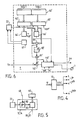
- FIG. 7 it is shown how the switches 45 and 47 can be operated.
- the switch 47 When in standby, the switch 47 is put in a position such that the phase shift member 20 does not provide any phase correction, while the switch 45 is put in a position which allows the phase shift member 50 to already receive the first value found Ferr. Then in a following period, we are in traffic mode, the switches 45 and 47 are inverted so that the filtered phase error values Ferr, Ferr ′ are applied to the member 20 at each period and no more errors phase is not applied to the member 50. Thus, corrected data has been supplied to the equalizer 29.
Abstract
Description
La présente invention concerne un procédé de synchronisation par corrélation, procédé impliquant une première étape pendant laquelle des données de synchronisation représentant une séquence de synchronisation sont reçues, centrées autour d'une fréquence porteuse, d'une deuxième étape de corrélations partielles où l'on effectue la corrélation des données reçues avec des parties de la séquence de synchronisation engendrée localement, une troisième étape pour fournir une indication d'erreur sur la fréquence porteuse reçue à partir des corrélations partielles et une quatrième étape pour fournir à l'utilisation un pic de corrélation.The present invention relates to a correlation synchronization method, a method involving a first step during which synchronization data representing a synchronization sequence is received, centered around a carrier frequency, from a second partial correlation step in which correlates the received data with parts of the locally generated synchronization sequence, a third step to provide an error indication on the carrier frequency received from the partial correlations and a fourth step to provide the usage with a peak correlation.
L'invention trouve d'importantes applications surtout dans le domaine des transmissions de données par voie radioélectrique ou les contraintes sont sévères du fait des fortes perturbations auxquelles sont soumises ces voies.The invention finds important applications especially in the field of data transmission by radio channel where the constraints are severe due to the strong disturbances to which these channels are subjected.
Le brevet français n°2 525 055 décrit un tel procédé qui satisfait toutes les exigences en ce qui concerne la précision de la synchronisation. Cependant il s'est avéré que la charge de calcul était trop élevée pour certaines applications.French Patent No. 2,525,055 describes such a process which satisfies all the requirements as regards the precision of synchronization. However, it turned out that the computational load was too high for certain applications.
L'invention propose un procédé qui implique moins de calculs de sorte que lorsque la mise en oeuvre du procédé est exécutée par un ensemble à microprocesseur, celui-ci peut être affecté à des tâches supplémentaires.The invention provides a method which involves fewer calculations so that when the implementation of the method is carried out by a microprocessor assembly, the latter can be assigned to additional tasks.
Pour cela, un procédé du genre mentionné dans le préambule est remarquable en ce que dans la troisième étape, on sélectionne des corrélations partielles exécutées durant la deuxième étape et l'indication d'erreur est établie sur ces corrélations sélectionnées.For this, a method of the kind mentioned in the preamble is remarkable in that in the third step, partial correlations executed during the second step are selected and the error indication is established on these selected correlations.
La description suivante accompagnée des dessins ci-annexés, le tout donné à titre d'exemple non limitatif, fera bien comprendre comment l'invention peut être réalisée.
- La figure 1 est un schéma montrant un récepteur permettant la mise en oeuvre du procédé de l'invention.
- La figure 2 illustre une trame de données transmises .
- La figure 3 est un schéma fonctionnel pour expliquer le fonctionnement de la synchronisation en mode de veille.
- La figure 4 montre l'engendrement d'un vecteur d'erreur de fréquence à partir de l'indication d'erreur établie durant la troisième étape.
- La figure 5 montre la correction de fréquence apportée pour effectuer la corrélation totale.
- La figure 6 est un schéma fonctionnel pour expliquer le fonctionnement de la synchronisation en mode trafic.
- La figure 7 montre comment les indications d'erreur peuvent être utilisées pour compenser les erreurs de fréquence de la porteuse reçue.
- FIG. 1 is a diagram showing a receiver allowing the implementation of the method of the invention.
- FIG. 2 illustrates a frame of transmitted data.
- Figure 3 is a block diagram for explaining the operation of synchronization in standby mode.
- FIG. 4 shows the generation of a frequency error vector from the error indication established during the third step.
- Figure 5 shows the frequency correction made to perform the total correlation.
- Figure 6 is a block diagram for explaining the operation of synchronization in traffic mode.
- Figure 7 shows how error indications can be used to compensate for frequency errors of the received carrier.
A la figure 1, la référence 1 indique une antenne qui reçoit des données transmises dans la gamme hf, c'est-à-dire dans une gamme allant entre 1 MHz et 30 MHz par exemple. Les données utilisées pour la synchronisation sont bivalentes une première valeur est représentée par une phase de 0 degré d'une sous-porteuse à 1800 Hz et une seconde par une phase de 180 degrés de cette même porteuse. En d'autres termes, les données ont pour valeurs au départ : +1 et -1.In FIG. 1, the
Par suite de la transmission, ces valeurs vont subir des fluctuations d'amplitude et de phase et même vont s'interpénétrer. Le récepteur montré à la figure 1 fournit à la borne de sortie 5 des données débarrassées, dans la mesure du possible, de ces fluctuations et de cette interpénétration.As a result of the transmission, these values will undergo amplitude and phase fluctuations and even will interpenetrate. The receiver shown in FIG. 1 supplies the output terminal 5 with data free, as far as possible, of these fluctuations and this interpenetration.
A la figure 2, on a représenté schématiquement une trame de données reçues. Ainsi, les données de synchronisation sont représentées par une séquence SQ ; après cette séquence, les données utiles DU. Seules, ces données DU apparaissent sur la borne 5. A la figure 7 surgit un signal indiquant qu'une séquence de données de synchronisation a été reçue.In Figure 2, there is shown schematically a frame of received data. So the synchronization data are represented by an SQ sequence; after this sequence, the useful data DU. Only this DU data appears on terminal 5. In FIG. 7, a signal appears indicating that a sequence of synchronization data has been received.
A la figure 1, la référence 8 indique la partie réception du récepteur. A sa sortie, on a les données transmises par la sous-porteuse. Un convertisseur analogique-numérique 10 fournit des sous-échantillons numériques à une cadence N fois plus rapide que la transmission des données. C'est-à-dire que pour une données transmise, on aura N sous-échantillons. Pour la suite de l'exposé, N sera pris égal à 4.In FIG. 1, the reference 8 indicates the reception part of the receiver. At its output, we have the data transmitted by the subcarrier. An analog-digital converter 10 provides digital sub-samples at a rate N times faster than the data transmission. That is to say that for a transmitted data, there will be N subsamples. For the rest of the presentation, N will be taken equal to 4.
Un ensemble à microprocesseur 12 effectue un traitement sur ces échantillons pour fournir les informations utiles aux bornes 5 et 7. Pour des raisons de clarté, cet ensemble est montré sous forme de schéma blocs, mais il est évident pour un homme de l'art de transformer ce schéma en blocs fonctionnels interprétables par un microprocesseur. Les échantillons à la sortie du convertisseur 10 sont tout d'abord démoulés à la fréquence nominale de la sous-porteuse à 1800 Hz. Pour cela, deux organes de multiplication 14 et 15 sont utilisés suivis de deux filtres passe-bas 16 et 17 de sorte qu'à leur sortie on fait apparaître réelle et imaginaire respectivement, en bande de base, des données transmises. L'organe 14 multiplie les échantillons par cos 2πFt et l'organe 15 par sin 2πFt où F est la fréquence de la sous-porteuse. La grandeur complexe ainsi élaborée est soumise ensuite à l'action d'un organe de déphasage 20 qui la déphase selon une grandeur appliquée à son entrée de commande de déphasage 21. Les échantillons, partie réelle et partie imaginaire, à la sortie de l'organe 20 sont emmagasinés systématiquement aux quatre positions (correspondant à la valeur N) successives d'une mémoire tampon 22 à adressage circulaire. Cette mémoire pouvant contenir une centaine de données. Cette mémoire sera adressée en lecture pour le traitement qui va être décrit par un numéro de symbole "ns" qui définit la donnée et un numéro d'indice "i" qui définit la position du sous-échantillon. Ainsi des sous-échantillons contenus dans cette mémoire 22 peuvent être prélevés de façon sélective par un organe d'entrée d'égalisateur 25, d'une part, et par un organe de synchronisation 27, d'autre part. La sortie de l'organe 25 est reliée à l'entrée d'un égalisateur 29 suivi d'un organe de décision 31 pour fournir les données à la borne 5.A microprocessor assembly 12 performs processing on these samples to provide the information useful at
L'organe de synchronisation 27 fournit, non seulement sur la borne 7 le pic indiquant qu'une séquence de données de synchronisation a été reçue, ainsi que cela a été dit, mais fournit en plus :
- sur une sortie 40, une valeur d'indice, accompagnée du numéro,de symbole pour indiquer le numéro du sous-échantillon à considérer par l'organe 25,
- sur une sortie 42, une autre valeur d'indice, accompagnée du numéro de symbole pour son traitement propre, et
- sur une sortie 44, une erreur de phase pour être utilisée soit par l'organe 25 via un commutateur 45, soit par un filtre 46. La sortie de ce filtre 46 est reliée à l'organe 20 via un commutateur 47. Cette erreur de phase représente la différence entre la valeur nominale de la sous-porteuse et la valeur de la sous-porteuse reçue, cette erreur pouvant être due à des effets doppler ou à des écarts de fréquence entre les porteuses.The
- on an
- on an
- On an
L'organe d'entrée d'égaliseur 25 est formé d'un organe de déphasage 50 suivi d'un organe de normalisation 52 qui centre les valeurs des données pour que l'égalisation puisse s'effectuer dans les meilleures conditions possibles.The
Le fonctionnement d'un tel récepteur se décompose en deux modes de travail. Un mode est dit le mode de veille pendant lequel une synchronisation est obtenue ce qui fait passer le récepteur dans le mode trafic. Les deux modes transmettent des données utiles.The operation of such a receiver is broken down into two working modes. A mode is said to be the standby mode during which synchronization is obtained, which places the receiver in traffic mode. Both modes transmit useful data.
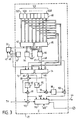
L'organe de synchronisation 27 représenté à la figure 3 sous forme de blocs fonctionnels est affecté au mode veille. Le bloc 60 représente la séquence des données S(k) du code de synchronisation SQ ayant par exemple 80 valeurs ce code est divisé en 8 parties SQ1, SQ2, ..., SQ8 de 10 valeurs chacune. Les données reçues, prélevées dans la mémoire 22 au moyen d'un organe d'adressage 61 sont corrélées au moyen d'un organe représenté par un bloc 62 à ces différentes parties de blocs et selon un aspect de l'invention, ces corrélations ne sont effectuées que sur les parties SQ1 à SQ4. Un organe de sélection 64 détermine parmi les corrélations effectuées pour chacun des quatre sous-échantillons et pour chacune de ces parties celle qui donne le meilleur résultat.The
Pour cela, on détermine le "i" qui maximilise la formule suivante :

La valeur "iopt" est utilisée par un bloc 65 pour effectuer des corrélations avec ces indices sur les parties de séquence SQ5 à SQ8. Toutes ces corrélations avec cette valeur servent pour calculer l'erreur de phase selon une méthode similaire à celle décrite dans le brevet précité. On obtient une fonction f(φ) :
f(φ) = K.exp(10.φ)
où K est une constante.
De cette valeur de φ on peut en dériver un vecteur![]()
V(k) = exp(-j(k-1)φ)
kε[1,80]
La valeur φ apparaît à la sortie 67 et le vecteur![]()
f (φ) = K.exp (10.φ)
where K is a constant.
From this value of φ we can derive a vector ![]()
V (k) = exp (-j (k-1) φ)
kε [1,80]
The value φ appears at ![]()
Deux blocs 72 et 74 effectuent une corrélation totale en opérant sur deux moitiés du code SQ. Chacun de ces blocs comporte, comme indiqué à la figure 5, un organe de déphasage 80 suivi d'un organe de corrélation 82 proprement dit ; l'organe 80 a sa commande de déphasage reliée à la sortie 68 pour déphaser les données prélevées dans la mémoire 22. Ainsi cette corrélation va s'effectuer dans de bonnes conditions puisque l'écart de fréquence est déjà corrigé.Two
Les corrélations effectuées par les blocs 72 et 74 sont respectivement CORT(iopt,1) et CORT(iopt,2) données par
CORTOTAL = CORT(iopt,1) + CORT(iopt,2)
Cette somme est faite par l'additionneur 89.The correlations made by
CORTOTAL = CORT (iopt, 1) + CORT (iopt, 2)
This sum is made by the
On détermine le carré du module de CORTOTAL au moyen des éléments 90 et 91 qui l'un prend la quantité conjuguée de CORTOTAL et l'autre multiplie entre elles ces valeurs. On évalue aussi la quantité suivante au moyen d'un élément 95 pour déterminer la valeur conjuguée de CORT(iopt,1) et d'un multiplieur 96.
[CORT5(iopt,1)]* . CORT(iopt,2)
Cette quantité donne après traitement dans un organe 98 une phase qui additionnée à celle (sortie 67) préalablement calculée dans le bloc 66, au moyen d'un additionneur 100 améliore cette dernière d'une manière sensible.One determines the square of the module of CORTOTAL by means of the
[CORT5 (iopt, 1)] *. CORT (iopt, 2)
This quantity gives, after treatment in an
Un bloc final 110 traite l'infomation à la sortie de l'élément 91 et aussi celle fournie par un organe de comparaison 112 pour prendre certaines mesures lorsque un pic de corrélation a été déterminé par l'organe 112 qui compare la valeur du module de CORTOTAL avec une valeur de seuil TH préalablement établie. Une de ces mesures consiste à définir la valeur "ns" pour laquelle la synchronisation a été détectée. Une autre mesure consite à mémoriser la valeur de phase calculée en sortie de l'additionneur 100 et "iopt".A
Une fois que la synchronisation a été obtenue, le récepteur passe en mode trafic pour la trame suivante. La synchronisation a alors un rôle de surveillance pour savoir si le code de synchronisation est toujours bien reconnu et aussi de surveiller la phase afin de corriger des écarts faibles de sous-porteuses toujours possibles. La figure 6 montre comment l'organe 27 est organisé pour ce mode.Once synchronization has been obtained, the receiver switches to traffic mode for the next frame. Synchronization then has a monitoring role to know if the synchronization code is still well recognized and also to monitor the phase in order to correct small deviations of subcarriers always possible. Figure 6 shows how the
Ici, le code de synchronisation est divisé en deux parties SQQ1 et SQQ2 dans un bloc 60′. Dans un bloc 62′, on évalue les corrélations pour tous les indices "i" élaborés par l'organe d'adressage 61′ avec la partie de code SQQ1 un organe 64′ détermine comme en mode veille la valeur "iopt" de sorte que un bloc 65′ calcule la corrélation pour ce "iopt" des données avec la demi-séquence SQQ2. A partir de ces deux corrélations, on détermine une valeur d'erreur de phase au moyen d'un organe 66 en prenant le conjugué de la corrélation donnée par 62′ et la corrélation par 65′. Puis la corrélation totale est calculée en additionnant celles obtenues par les organes 62′ et 66′. Le carré du module est obtenu, comme en mode veille au moyen des éléments 89′, 90′ et 91′ semblables aux éléments 89, 90 et 91 décrits à la figure 3. La synchronisation est détectée par l'organe de comparaison 112′ et le bloc final 110′ a la même fonction que le bloc 110. Pour ce bloc l'erreur de phase considérée est seulement celle fournie par l'organe 66′ à partir du conjugué de la corrélation fournie par le bloc 62′ et celle du bloc 65′.Here, the synchronization code is divided into two parts SQQ1 and SQQ2 in a
A la figure 7, on montre comment les commutateurs 45 et 47 peuvent être manoeuvrés. Lorsqu'on est en veille, le commutateur 47 est mis dans une position telle que l'organe de déphasage 20 n'apporte aucune correction de phase, tandis que le commutateur 45 est mis dans une position qui permet à l'organe de déphasage 50 de recevoir déjà la première valeur trouvée Ferr. Puis dans une période suivante, on se trouve en mode trafic, les commutateurs 45 et 47 s'inversent de sorte que les valeurs d'erreur de phase filtrées Ferr, Ferr' sont appliquées à l'organe 20 à chaque période et plus aucune erreur de phase n'est appliquée à l'organe 50. Ainsi, on a fourni des données corrigées à l'égaliseur 29.In FIG. 7, it is shown how the
Claims (1)
Applications Claiming Priority (2)
| Application Number | Priority Date | Filing Date | Title |
|---|---|---|---|
| FR8910188 | 1989-07-28 | ||
| FR8910188A FR2650456A1 (en) | 1989-07-28 | 1989-07-28 | CORRELATION SYNCHRONIZATION METHOD |
Publications (2)
| Publication Number | Publication Date |
|---|---|
| EP0410532A1 true EP0410532A1 (en) | 1991-01-30 |
| EP0410532B1 EP0410532B1 (en) | 1995-03-29 |
Family
ID=9384236
Family Applications (1)
| Application Number | Title | Priority Date | Filing Date |
|---|---|---|---|
| EP90202008A Expired - Lifetime EP0410532B1 (en) | 1989-07-28 | 1990-07-23 | Method of synchronization by correlation |
Country Status (7)
| Country | Link |
|---|---|
| US (1) | US5090028A (en) |
| EP (1) | EP0410532B1 (en) |
| JP (1) | JPH0370231A (en) |
| CA (1) | CA2021974A1 (en) |
| DE (1) | DE69018149D1 (en) |
| FI (1) | FI903726A0 (en) |
| FR (1) | FR2650456A1 (en) |
Cited By (3)
| Publication number | Priority date | Publication date | Assignee | Title |
|---|---|---|---|---|
| EP0711049A1 (en) * | 1994-11-07 | 1996-05-08 | Alcatel Telspace | Method for the detection of reference symbols for a digital data receiver |
| EP0734136A1 (en) * | 1995-03-22 | 1996-09-25 | Sagem Sa | Method of transmitting digital data and receiver for implementing the method |
| SG85064A1 (en) * | 1992-05-29 | 2001-12-19 | Motorola Inc | Data communication receiver having burst error protected data synchronization |
Families Citing this family (20)
| Publication number | Priority date | Publication date | Assignee | Title |
|---|---|---|---|---|
| SE469678B (en) * | 1992-01-13 | 1993-08-16 | Ericsson Telefon Ab L M | SET FOR SYNCHRONIZATION AND CHANNEL TESTING IN TDMA RADIO SYSTEM |
| US6226336B1 (en) * | 1998-02-20 | 2001-05-01 | Telefonaktiebolaget Lm Ericsson (Publ) | Method and apparatus for detecting a frequency synchronization signal |
| US6421371B1 (en) * | 1998-11-17 | 2002-07-16 | Ericsson Inc. | Modulation sequence synchronization methods and apparatus employing partial sequence correlation |
| GB2347831B (en) * | 1999-03-06 | 2004-07-07 | Nec Technologies | Sychronisation in digital data transmission systems |
| US9020756B2 (en) * | 1999-04-23 | 2015-04-28 | Global Locate, Inc. | Method and apparatus for processing satellite positioning system signals |
| US6606346B2 (en) * | 2001-05-18 | 2003-08-12 | Global Locate, Inc. | Method and apparatus for computing signal correlation |
| US6704348B2 (en) | 2001-05-18 | 2004-03-09 | Global Locate, Inc. | Method and apparatus for computing signal correlation at multiple resolutions |
| DE19953350A1 (en) * | 1999-11-05 | 2001-05-23 | Infineon Technologies Ag | Device for fine synchronization of code signals |
| US7995682B2 (en) * | 2001-05-18 | 2011-08-09 | Broadcom Corporation | Method and apparatus for performing signal processing using historical correlation data |
| US7190712B2 (en) * | 2001-05-18 | 2007-03-13 | Global Locate, Inc | Method and apparatus for performing signal correlation |
| US6819707B2 (en) | 2001-05-18 | 2004-11-16 | Global Locate, Inc. | Method and apparatus for performing signal correlation using historical correlation data |
| US7006556B2 (en) * | 2001-05-18 | 2006-02-28 | Global Locate, Inc. | Method and apparatus for performing signal correlation at multiple resolutions to mitigate multipath interference |
| US8098716B2 (en) * | 2001-05-18 | 2012-01-17 | Broadcom Corporation | Method and apparatus for providing an energy-based signal tracking loop |
| US7769076B2 (en) | 2001-05-18 | 2010-08-03 | Broadcom Corporation | Method and apparatus for performing frequency synchronization |
| US6891880B2 (en) * | 2001-05-18 | 2005-05-10 | Global Locate, Inc. | Method and apparatus for performing signal correlation |
| US7567636B2 (en) | 2001-05-18 | 2009-07-28 | Global Locate, Inc. | Method and apparatus for performing signal correlation using historical correlation data |
| US7064466B2 (en) * | 2001-11-27 | 2006-06-20 | Denso Corporation | Brushless rotary electric machine having tandem rotary cores |
| SG108874A1 (en) * | 2002-09-17 | 2005-02-28 | Sony Corp | Channel equalisation |
| DE102004059958B4 (en) * | 2004-12-13 | 2007-10-04 | Fraunhofer-Gesellschaft zur Förderung der angewandten Forschung e.V. | Apparatus and method for determining a correlation value |
| DE102004059957A1 (en) * | 2004-12-13 | 2006-06-14 | Fraunhofer-Gesellschaft zur Förderung der angewandten Forschung e.V. | Synchronization device and device for generating a synchronization signal |
Citations (2)
| Publication number | Priority date | Publication date | Assignee | Title |
|---|---|---|---|---|
| US4238739A (en) * | 1979-02-26 | 1980-12-09 | E-Systems, Inc. | Preset network for a phase lock loop |
| EP0091167A1 (en) * | 1982-04-09 | 1983-10-12 | Telecommunications Radioelectriques Et Telephoniques T.R.T. | Method of correcting the frequency of the local carrier in the receiver of a data transmission system, and receiver utilizing this method |
Family Cites Families (7)
| Publication number | Priority date | Publication date | Assignee | Title |
|---|---|---|---|---|
| US4203071A (en) * | 1978-08-08 | 1980-05-13 | The Charles Stark Draper Laboratory, Inc. | Pseudo-random-number-code-detection and tracking system |
| US4485477A (en) * | 1982-07-19 | 1984-11-27 | Rca Corporation | Fast frequency/code search |
| US4621365A (en) * | 1984-11-16 | 1986-11-04 | Hughes Aircraft Company | Synchronization preamble correlation detector and frequency estimator |
| US4649543A (en) * | 1985-08-30 | 1987-03-10 | Motorola, Inc. | Synchronization sequence decoder for a digital radiotelephone system |
| GB2206267B (en) * | 1987-06-24 | 1991-09-25 | Plessey Co Plc | Novel correlator for synchronisation detection |
| US4847869A (en) * | 1987-12-04 | 1989-07-11 | Motorla, Inc. | Rapid reference acquisition and phase error compensation for radio transmission of data |
| US4829543A (en) * | 1987-12-04 | 1989-05-09 | Motorola, Inc. | Phase-coherent TDMA quadrature receiver for multipath fading channels |
-
1989
- 1989-07-28 FR FR8910188A patent/FR2650456A1/en active Granted
-
1990
- 1990-07-23 EP EP90202008A patent/EP0410532B1/en not_active Expired - Lifetime
- 1990-07-23 DE DE69018149T patent/DE69018149D1/en not_active Expired - Lifetime
- 1990-07-25 CA CA002021974A patent/CA2021974A1/en not_active Abandoned
- 1990-07-25 FI FI903726A patent/FI903726A0/en not_active IP Right Cessation
- 1990-07-25 JP JP2197566A patent/JPH0370231A/en active Pending
- 1990-07-27 US US07/558,715 patent/US5090028A/en not_active Expired - Fee Related
Patent Citations (2)
| Publication number | Priority date | Publication date | Assignee | Title |
|---|---|---|---|---|
| US4238739A (en) * | 1979-02-26 | 1980-12-09 | E-Systems, Inc. | Preset network for a phase lock loop |
| EP0091167A1 (en) * | 1982-04-09 | 1983-10-12 | Telecommunications Radioelectriques Et Telephoniques T.R.T. | Method of correcting the frequency of the local carrier in the receiver of a data transmission system, and receiver utilizing this method |
Cited By (6)
| Publication number | Priority date | Publication date | Assignee | Title |
|---|---|---|---|---|
| SG85064A1 (en) * | 1992-05-29 | 2001-12-19 | Motorola Inc | Data communication receiver having burst error protected data synchronization |
| EP0711049A1 (en) * | 1994-11-07 | 1996-05-08 | Alcatel Telspace | Method for the detection of reference symbols for a digital data receiver |
| FR2726711A1 (en) * | 1994-11-07 | 1996-05-10 | Alcatel Telspace | REFERENCE SYMBOL DETECTION PROCESS FOR DIGITAL DATA RECEIVERS |
| US5732114A (en) * | 1994-11-07 | 1998-03-24 | Alcatel Telspace | Method of detecting reference symbols for a digital data receiver |
| EP0734136A1 (en) * | 1995-03-22 | 1996-09-25 | Sagem Sa | Method of transmitting digital data and receiver for implementing the method |
| FR2732176A1 (en) * | 1995-03-22 | 1996-09-27 | Sagem | METHOD FOR TRANSMITTING DIGITAL DATA AND RECEIVER FOR IMPLEMENTING THE METHOD |
Also Published As
| Publication number | Publication date |
|---|---|
| FR2650456B1 (en) | 1994-07-13 |
| JPH0370231A (en) | 1991-03-26 |
| CA2021974A1 (en) | 1991-01-29 |
| EP0410532B1 (en) | 1995-03-29 |
| DE69018149D1 (en) | 1995-05-04 |
| FI903726A0 (en) | 1990-07-25 |
| US5090028A (en) | 1992-02-18 |
| FR2650456A1 (en) | 1991-02-01 |
Similar Documents
| Publication | Publication Date | Title |
|---|---|---|
| EP0410532B1 (en) | Method of synchronization by correlation | |
| EP0091167B1 (en) | Method of correcting the frequency of the local carrier in the receiver of a data transmission system, and receiver utilizing this method | |
| CA2187122C (en) | Distance measurement wideband receiver using pseudo-random code signals | |
| EP0291979B1 (en) | Method for demodulating digitally modulated signals, and device for carrying out the method | |
| EP0451232B1 (en) | Code acquisition method and circuit for a spread spectrum signal receiver | |
| FR2550030A1 (en) | METHOD AND DEVICE FOR DEMODULATING FREQUENCY MODULATION | |
| FR2739938A1 (en) | RECEIVER FOR DETERMINING A POSITION FROM SATELLITE ARRAYS | |
| FR2770700A1 (en) | DEVICE AND METHOD FOR SYNCHRONIZING OSCILLATORS IN A DATA COMMUNICATION SYSTEM | |
| FR2620583A1 (en) | MODEM TRANSMISSION SYSTEM HAVING MAIN AND SECONDARY CHANNELS | |
| EP0004822A1 (en) | Method and apparatus for demodulating a differential phase shift keying signal | |
| FR2479629A1 (en) | METHOD FOR DEMODULATING AN AMPLITUDE MODULE SIGNAL, DEMODULATOR USING THE METHOD AND TELEVISION SYSTEM COMPRISING SUCH A DEVICE | |
| EP2095150B1 (en) | Method and device for receiving a boc modulation radio-navigation signal | |
| EP0029376B1 (en) | Frequency modulated signal demodulation process and demodulator putting this process into operation | |
| EP3116182B1 (en) | Quadrature demodulator for very high throughput rfid receiver | |
| EP0059138B1 (en) | Method of radio-localisation by determining the phases of electromagnetic waves, and receiver apparatus therefor | |
| EP1094631A1 (en) | Quest for the optimum sampling point in a TDMA packet transmission system | |
| EP0080544A1 (en) | Method for receiving a data signal with double side-band quadrature carrier modulation | |
| EP0061377B1 (en) | Digital signal demodulator and a colour television receiver or system comprising such a demodulator | |
| EP0737868B1 (en) | Delay locked loop for use in a GPS receiver | |
| EP0097754A1 (en) | Tone detector and multifrequency receiver using this detector | |
| EP1142147B1 (en) | Method for receiving spectrum spread signals with frequency offset correction | |
| FR3044104A1 (en) | RECEIVER FOR SATELLITE POSITIONING SYSTEM AND METHOD OF PROCESSING SATELLITE SIGNALS | |
| EP0201946A1 (en) | Device for measuring the speed relative to a surface | |
| EP0082750B1 (en) | Receiving arrangement for at least two radionavigation systems | |
| FR2472307A1 (en) | LOW PHASE DISTORTION FILTERING DEVICE AND COLOR TELEVISION SIGNAL PROCESSING CIRCUIT COMPRISING SUCH A DEVICE |
Legal Events
| Date | Code | Title | Description |
|---|---|---|---|
| PUAI | Public reference made under article 153(3) epc to a published international application that has entered the european phase |
Free format text: ORIGINAL CODE: 0009012 |
|
| AK | Designated contracting states |
Kind code of ref document: A1 Designated state(s): DE FR GB IT SE |
|
| 17P | Request for examination filed |
Effective date: 19910725 |
|
| 17Q | First examination report despatched |
Effective date: 19930907 |
|
| GRAA | (expected) grant |
Free format text: ORIGINAL CODE: 0009210 |
|
| AK | Designated contracting states |
Kind code of ref document: B1 Designated state(s): DE FR GB IT SE |
|
| PG25 | Lapsed in a contracting state [announced via postgrant information from national office to epo] |
Ref country code: IT Free format text: LAPSE BECAUSE OF FAILURE TO SUBMIT A TRANSLATION OF THE DESCRIPTION OR TO PAY THE FEE WITHIN THE PRE;WARNING: LAPSES OF ITALIAN PATENTS WITH EFFECTIVE DATE BEFORE 2007 MAY HAVE OCCURRED AT ANY TIME BEFORE 2007. THE CORRECT EFFECTIVE DATE MAY BE DIFFERENT FROM THE ONE RECORDED.SCRIBED TIME-LIMIT Effective date: 19950329 Ref country code: GB Effective date: 19950329 |
|
| REF | Corresponds to: |
Ref document number: 69018149 Country of ref document: DE Date of ref document: 19950504 |
|
| PG25 | Lapsed in a contracting state [announced via postgrant information from national office to epo] |
Ref country code: SE Effective date: 19950629 |
|
| PG25 | Lapsed in a contracting state [announced via postgrant information from national office to epo] |
Ref country code: DE Effective date: 19950630 |
|
| PGFP | Annual fee paid to national office [announced via postgrant information from national office to epo] |
Ref country code: FR Payment date: 19950725 Year of fee payment: 6 |
|
| GBV | Gb: ep patent (uk) treated as always having been void in accordance with gb section 77(7)/1977 [no translation filed] |
Effective date: 19950329 |
|
| PLBE | No opposition filed within time limit |
Free format text: ORIGINAL CODE: 0009261 |
|
| STAA | Information on the status of an ep patent application or granted ep patent |
Free format text: STATUS: NO OPPOSITION FILED WITHIN TIME LIMIT |
|
| 26N | No opposition filed | ||
| PG25 | Lapsed in a contracting state [announced via postgrant information from national office to epo] |
Ref country code: FR Effective date: 19970328 |
|
| REG | Reference to a national code |
Ref country code: FR Ref legal event code: ST |