EP0410484A1 - Process for adapting the total light intensity to the outside light intensity - Google Patents
Process for adapting the total light intensity to the outside light intensity Download PDFInfo
- Publication number
- EP0410484A1 EP0410484A1 EP90114487A EP90114487A EP0410484A1 EP 0410484 A1 EP0410484 A1 EP 0410484A1 EP 90114487 A EP90114487 A EP 90114487A EP 90114487 A EP90114487 A EP 90114487A EP 0410484 A1 EP0410484 A1 EP 0410484A1
- Authority
- EP
- European Patent Office
- Prior art keywords
- light
- light intensity
- room
- outside
- function
- Prior art date
- Legal status (The legal status is an assumption and is not a legal conclusion. Google has not performed a legal analysis and makes no representation as to the accuracy of the status listed.)
- Granted
Links
Images

Classifications
-
- H—ELECTRICITY
- H05—ELECTRIC TECHNIQUES NOT OTHERWISE PROVIDED FOR
- H05B—ELECTRIC HEATING; ELECTRIC LIGHT SOURCES NOT OTHERWISE PROVIDED FOR; CIRCUIT ARRANGEMENTS FOR ELECTRIC LIGHT SOURCES, IN GENERAL
- H05B41/00—Circuit arrangements or apparatus for igniting or operating discharge lamps
- H05B41/14—Circuit arrangements
- H05B41/36—Controlling
- H05B41/38—Controlling the intensity of light
- H05B41/39—Controlling the intensity of light continuously
- H05B41/392—Controlling the intensity of light continuously using semiconductor devices, e.g. thyristor
- H05B41/3921—Controlling the intensity of light continuously using semiconductor devices, e.g. thyristor with possibility of light intensity variations
- H05B41/3922—Controlling the intensity of light continuously using semiconductor devices, e.g. thyristor with possibility of light intensity variations and measurement of the incident light
-
- H—ELECTRICITY
- H05—ELECTRIC TECHNIQUES NOT OTHERWISE PROVIDED FOR
- H05B—ELECTRIC HEATING; ELECTRIC LIGHT SOURCES NOT OTHERWISE PROVIDED FOR; CIRCUIT ARRANGEMENTS FOR ELECTRIC LIGHT SOURCES, IN GENERAL
- H05B39/00—Circuit arrangements or apparatus for operating incandescent light sources
- H05B39/04—Controlling
- H05B39/041—Controlling the light-intensity of the source
- H05B39/042—Controlling the light-intensity of the source by measuring the incident light
Definitions
- the invention relates to a method for adapting the luminous intensity of the total light according to the preamble of claim 1.
- Methods of this type are used to compensate for fluctuations in light intensity in a room caused by changing outside light.
- an outside light sensor is arranged outside the room to be illuminated.
- An external light-dependent control of the light intensity of the interior light takes place in opposite directions; with decreasing outside light, the interior light of the room is controlled brighter.
- a light-sensitive sensor part is connected to a control part, which in turn controls a dimmer circuit part.
- the dimmer circuit part controls light sources arranged in the room, which generate a dimmed light level.
- the light-sensitive sensor part is arranged so that it cannot detect the dimmed light level of the light sources.
- the light sources are controlled in accordance with a linear, opposing dependence of the dimmed light level on the sensed sensor signal. The inclination of this function, which defines the dependence, is set by a gradient factor.
- the setting is made at any time of day when the lighting arrangement is started up.
- Such a method has the disadvantage that not only the dimmed light level present at the time of the adjustment is changed with the setting of the slope of the linear function, but also the dimmed light levels assigned to all other light intensities of the outside light are changed.
- the invention is based on the object of specifying a method and a circuit arrangement in which there are refined setting options for adapting the light intensity in a room.
- the object is achieved in a method of the type mentioned at the outset in that the dependency function is determined by a plurality of function values which can be set independently of one another and in that each function value can be changed independently of other function values.
- the invention makes use of the consideration that an individual lighting requirement is not met by specifying a single parameter of the function, for example the slope or the parallel displacement, but that this can only be met by specifying the function individually or in sections.
- the invention makes use of the knowledge that even a complicated dependency of the light intensity of the interior light on the light intensity of the exterior light, the total light or the time can be determined independently by relatively few Lets define function values. Thus, with individual ease of use, all individual lighting requirements are taken into account.
- Claim 6 is directed to the adaptation of the structural illumination of a room, which can not only be dependent on the outside light intensity but also on the direction of the daylight. According to the invention, the distribution of the light intensity in the room can be adjusted depending on the daylight, so that a certain, if necessary, uneven light distribution can be realized in the room.
- An observer present in a room perceives the sum of the luminous intensity of the incident external light E ' i and the artificially generated internal light E k as the total luminous intensity of the summed light E i .
- the person present in the room can now, according to the characterizing part of claim 1, on the one hand at any time of the day and on the other hand at any light ratio a corresponding light intensity of the interior light and thus the light intensity of the total light. that is, choose the interior brightness without the person itself being burdened with the actual function of the dependency. According to the invention, this function is determined by selecting individual points.
- the invention is explained in more detail below on the basis of exemplary embodiments.
- FIG. 1 shows an exemplary embodiment of the invention with an outside light sensor 1, a dimmer circuit part 3 and light sources 5, 6, 7 which can be connected to this.
- the dimmer circuit part 3 has a control circuit part 2, a non-volatile read / write memory 8 and a plurality of dimmers 4, only one of which is shown to explain the mode of operation.
- Several lighting units can be provided in one room, each of which is controlled by the outside light (common outside light sensor) according to a different function.
- the different functions are stored in the preferably shared read / write memory 8.
- the outside light sensor 1 emits a light intensity-dependent control signal to the control circuit part 2, which in turn emits a predetermined phase control signal to the dimmer 4 according to defined values 11 in the memory 8, as a result of which the light intensity of the light sources 5, 6, 7 is set.
- Filament lamps 5, gas discharge lamps 6 or arc lamps 7 can be used as light sources, for example.
- electronic ballasts electronic ballasts
- the dimming function of which can be varied by varying their output frequency and / or their output duty cycle.
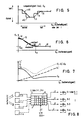
- FIG. 2 shows with curve shape a) a linearly falling light intensity of the interior light with increasing light intensity of the exterior light.
- a person present in the room can adjust a total luminous intensity E i by adjusting the slope or shift of the function a) in E k or in E a direction, which is constant, for example.
- a light intensity curve of the interior light according to curve c) is selected, there is also an area with increasing exterior brightness E a in which the intensity of the interior light E k is approximately proportional (concurrent) to the intensity of the exterior light E a .
- the double arrows marked on the functions a), b), c), c1), c2), c3) indicate a possibility of moving and changing them to adapt the desired function sequences. If individual points of the function curve c) or of the function curves c1), c2) or c3) are defined individually and independently of one another and stored in the memory 8, then a precise repeatability of a function once defined is possible.
- FIGS. 2, 3 and 6 are drawn continuously and continuously, one point-by-point storage and complete definition would require an infinite number of points. If, according to FIG. 5, a desired dependency ratio is now defined by a finite number of values 11, an interpolation to be determined beforehand specifies how the continuous function course controlling the light intensity is generated.
- FIG. 4 shows a light intensity function curve as a function of the time of day.
- the light intensity of the interior light E k and the times at which the desired and preset light intensities of the interior light are switched on can be recognized by the step-like function.
- An observer in a room now has the visual impression of outside light coming in through glass surfaces and the time-dependent controlled lamp light. For a specific day and a given weather ratio creates the individually desired room brightness or light intensity.
- FIG. 6 shows a special case of a light intensity curve E k of the interior light with a constant minimum.
- a light intensity curve as shown, would already be satisfactorily approachable with five values 12 in the case of linear interpolation.
- the lamp light intensity is basically (rough setting) controlled in a time-dependent manner, ie certain light levels are assigned basic light intensities, the fine adjustment in the direction of the double arrows in FIG. 4 is controlled by the light intensity of the outside light.
- the two dependencies can be interchanged, the basic light intensity is specified depending on the outside light, the fine influence on the light intensity E k takes place depending on the time. This results in a simplified possibility for an operator to influence.
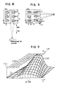
- FIG. 8 shows a further exemplary embodiment of the invention with an outside light sensor 1-1, a dimmer circuit part 3 and a plurality of light sources 5-1, 5-2, 5-3 and 5-4 which can be connected to this.
- the dimmer circuit part 3 has a control circuit part 2, a non-volatile read-write memory 8 and a plurality of dimmers 4-1, 4-2, 4-3 and 4-4.
- the control circuit part 2 is supplied with a control signal emitted by the outside light sensor 1-1 and each connectable light source, for example 5-4, is provided by a dimmer, for example wise 4-4, controlled.
- the control circuit part 2 is in one piece here, but can be designed in four parts for the control of the four dimmers 4-1, 4-2, 4-3, 4-4; these four control circuit parts are then controlled by a single outside light sensor 1-1 parallel to the input. Furthermore, a plurality of dimmer circuit parts 3-1, 3-2, 3-3 and 3-4 can also be used to control each of an interior light generator according to FIG. 1, the control signal emitted there by the exterior light sensor 1 being supplied to the plurality of dimmer circuit parts in parallel with the input. It goes without saying that the restriction to four dimmers or four dimmer circuit parts here is only of an exemplary nature; any number of dimmer circuit parts or dimmers with a corresponding number of interior light generators can be used.
- the non-volatile read-write memory 8 contains a multiplicity of values 11, 12 which define a plurality of functions c1, c2, c2, c4, c5 which can be changed independently of one another.
- the control signal which the outside light sensor 1-1 emits and which is supplied to the control circuit part (s) 2, 2-1, 2-2, 2-3, and 2-4 depending on four, the Variety of values 11, 12 defined different functions supplied to the four dimmers 4-1, 4-2, 4-3, 4-4 different predetermined phase control signals.
- the different functions for the control of the respective dimmer or interior light generator are stored together in the one non-volatile read / write memory 8.
- the multiple functions allow independent control of the interior light generators that can be installed in a room at different locations 5-1, 5-2, 5-3 or 5-4.
- All the control circuit parts 2-1, 2-2, 2-3, 2-4 which control the dimmers 4-1, 4-2, 4-3 or 4-4 receive the same light-intensity-dependent signal from the outside light sensor 1-1.
- a variant of the embodiment of FIG. 8 is that instead of the one outside light sensor 1-1, several outside light sensors, in the present case four outside light sensors 1-1, 1-2, 1-3 and 1-4, the four control circuit parts 2-1, Control 2-2, 2-3 or 2-4.
- An outside light sensor, for example 1-2 controls a control shading part, for example 2-2.
- Such a multidimensional arrangement can also be implemented by means of several different dimmer circuit parts 3-1, 3-2, 3-3 or 3-4.
- one dimmer circuit part, for example 3-1 is controlled by an outside light sensor, for example 1-1.
- the light intensity of the interior light can be influenced by the circuit arrangement according to FIG. 8 in the same way as, for example was shown in Figure 5.
- the nonlinearities occurring in the dimmer 4 ie the dependence of the light intensity of the interior light level on the ignition angle ⁇ (mains voltage phase gating angle) of the dimmer or the output frequency of an electronic ballast (EVG), were not mentioned in particular for the sake of clarity. However, these are taken into account by the control circuit part 2 when calculating, storing and changing light intensity values in the memory 8.
- FIGS. 9 and 10 each show the same room which has windows F1, F2 and F3, through which outside light E a can fall into said room E i '. At the same time, cardinal points are shown. Windows F1 and F2 are on the east side, window F3 is on the south side.
- six interior light generators (artificial light generators) 6-5, 6-6, 6-7, 6-8, 6-9 and 6-10 are attached to the ceiling in a symmetrical arrangement.
- a pair of sensors 1-5 and 1-6 is arranged in the southeast corner in FIG. 9, by means of which both the outside light intensity E a and its direction can be detected.
- FIG. 8 An x / y coordinate system is shown in the southwest corner, which illustrates the spatial dependence in space and corresponds to the x / y coordinate system of FIG. 11.
- six independently controllable dimmer circuit parts 4-5, 4-6, .... 4-10 are therefore to be provided.
- two independent exterior light sensors 1-5, 1-6 the first of which is in the east direction and the last one direction south oriented in, is provided, so a common control circuit part 2 can be provided, which from the outside direction of light and the external light luminance E a brightness values E k depending from the memory 8 individually supplies the six dimmer circuit parts for the six dimmer circuit parts. 4
- gas discharge lamps 6 are shown in FIGS. 9 and 10, as are preferably used for ceiling-mounted individual lighting or light band applications with frequency-controlled electronic ballasts (EVG).
- EDG electronic ballasts
- an additional interior light illumination (artificial light) E k (x, y) can now be generated in the room depending on the light intensity and the light direction in amplitude E k and location dependence x, y is chosen such that it complements the respective light E i ′ forms.
- the light 6-6 and the lamp 6-9 would have to be switched on or the brightness increased, for example, in the case of the incident light, the remaining four lamps could be switched off or reduced (dimmed) to a lower brightness value.
- This enables uniform daytime and season-independent room lighting E i (x, y) and saves energy at the same time.
- FIG. 11 shows the spatial dependence of the room brightness E i '(x, y).
- the cardinal direction drawn in this way forms the orientation such that the maximum of the interior light intensity E i 'is at the window F3 and this light intensity falls to the inside of the room both to the side and to the depth of the room.
- Figure 11 shows the location-dependent interior light intensity as a curved characteristic surface. If one wishes the aforementioned constant room brightness E i (x, y), which is essentially independent of location and thus guarantees an equal light level at every location in the room, the interior light generator arranged in the room, the location-dependent difference between E i (x, y) and E i ′ (x, y) are applied. This can be imagined with reference to FIG.
- the space between the (predetermined) E i characteristic surface or plane (light intensity distribution) and the incident outside light intensity distribution E i ' is supplemented by a location-dependent artificial light intensity distribution E k (x, y).
- the control circuit according to FIG. 8 is of great value since not only light generators can be switched on and off, but also any intermediate levels of light intensities can be generated depending on the location.
- the artificial light intensity distribution E k (x, y) required to supplement the incident outside light can be determined by specifying the point at points.
- function values 11 which, as explained in FIG. 5, can also define control characteristic curves (functions), set control surfaces (characteristic surfaces).
- Each dimmer circuit part 4-5, 4-6, ??, 4-10 which controls one of the interior light generators shown, receives its (light intensity) command variable individually from a control circuit part 2.
- This can also be a phase angle ⁇ if incandescent lamps with upstream dimmers are used.
- the respective individual reference variable is shown, for example, from the incident light on the two Outdoor light sensors 1-5 and 1-6 calculated.
- sensors can also be used. When using multiple outside light sensors, each outside light sensor is assigned a limited angular range within which it detects the light intensity (depending on the direction of the outside light). The respective recorded angular ranges per sensor directly or slightly overlap one another, so that a 270 ° detection (only north) is obtained.
- the elevation angle can also be included with the detected azimuth angle ranges, this corresponds to the seasonal steepness of the incidence of light. In the case of complete window fronts, the depth of the incident light changes here, this can be compensated for by the control according to FIG. 8.
- each of these interior light generators 6-5 is assigned an individual control characteristic area (artificial light intensity distribution) E k (x, y).
- E k artificial light intensity distribution
- amplitude values 11 for each interior light generator.
- a light intensity value for each interior light generator is determined individually on the basis of its characteristic characteristic surface and transmitted to the respective dimmer circuit part 4 as a phase angle, frequency value or desired luminance value.
- the respective individual characteristic surfaces thus form two-dimensional (curved) luminous intensity distributions which can be adapted to room conditions and window sizes or number of windows by changing their base values 11.
- a few interpolation points 11 are sufficient for the definition of a two-dimensional characteristic surface if the interpolation between the discrete interpolation points explained at the beginning is used.
- an essentially constant (overall) interior light intensity distribution E i (x, y) was mentioned as advantageous for office spaces or open-plan offices.
- the circuit arrangement according to FIG. 8 compensates for the outside light influences.
- the two external light sensors 1-5 and 1-6 shown in FIG. 9 are only arranged there by way of example in the southeast corner of the building or room; other attachment options and joint mounting on a roof of a building can also be used for the invention.
Landscapes
- Circuit Arrangement For Electric Light Sources In General (AREA)
- Radio Relay Systems (AREA)
- Mobile Radio Communication Systems (AREA)
- Polishing Bodies And Polishing Tools (AREA)
- Led Device Packages (AREA)
- Lighting Device Outwards From Vehicle And Optical Signal (AREA)
Abstract
Description
Die Erfindung betrifft ein Verfahren zur Anpassung der Lichtstärke des Summenlichtes nach dem Oberbegriff des Anspruches 1.The invention relates to a method for adapting the luminous intensity of the total light according to the preamble of claim 1.
Verfahren dieser Art finden Anwendung beim Ausgleich von durch wechselndes Außenlicht hervorgerufenen Lichtstärkeschwankungen in einem Raum. Zur Erfassung der Lichtstärke des Außenlichtes wird ein Außenlichtsensor außerhalb des zu beleuchtenden Raumes angeordnet. Eine außenlichtabhängige Steuerung der Lichtstärke des Innenlichtes erfolgt im wesentlichen gegenläufig; bei abnehmendem Außenlicht, wird das Innenlicht des Raumes heller gesteuert.Methods of this type are used to compensate for fluctuations in light intensity in a room caused by changing outside light. To detect the light intensity of the outside light, an outside light sensor is arranged outside the room to be illuminated. An external light-dependent control of the light intensity of the interior light takes place in opposite directions; with decreasing outside light, the interior light of the room is controlled brighter.
In "Journal of the Illuminating Engineering Society, (Winter 1989, Seiten 70-90)" werden ein Verfahren und eine Beleuchtungsanordnung zur Durchführung des Verfahrens für einen Raum gezeigt. Dort ist ein lichtempfindliches Sensorteil mit einem Steuerteil verbunden, das seinerseits ein Dimmerschaltungsteil steuert. Das Dimmerschaltungsteil steuert in dem Raum angeordnete Lichtquellen, welche einer gedimmten Lichtpegel erzeugen. Das lichtempfindliche Sensorteil ist so angeordnet, daß es den gedimmten Lichtpegel der Lichtquellen nicht erfassen kann. Die Steuerung der Lichtquellen erfolgt gemäß einer linearen gegenläufigen Abhängigkeit des gedimmten Lichtpegels von dem erfaßten Sensorsignal Die Neigung dieser, die Abhängigkeit definierenden Funktion wird durch einen Steigungsfaktor eingestellt.In "Journal of the Illuminating Engineering Society, (Winter 1989, pages 70-90)" a method and a lighting arrangement for carrying out the method for a room are shown. There, a light-sensitive sensor part is connected to a control part, which in turn controls a dimmer circuit part. The dimmer circuit part controls light sources arranged in the room, which generate a dimmed light level. The light-sensitive sensor part is arranged so that it cannot detect the dimmed light level of the light sources. The light sources are controlled in accordance with a linear, opposing dependence of the dimmed light level on the sensed sensor signal. The inclination of this function, which defines the dependence, is set by a gradient factor.
Die Einstellung erfolgt bei der Inbetriebnahme der Beleuchtungsanordnung zu einer beliebigen Tageszeit.The setting is made at any time of day when the lighting arrangement is started up.
Ein solches Verfahren hat den Nachteil, daß mit der Einstellung der Steigung der linearen Funktion nicht nur der zum Zeitpunkt des Abgleichs vorliegende gedimmte Lichtpegel verändert wird, sondern auch die allen anderen Lichtstärken des Außenlichtes zugeordneten gedimmten Lichtpegel verändert werden.Such a method has the disadvantage that not only the dimmed light level present at the time of the adjustment is changed with the setting of the slope of the linear function, but also the dimmed light levels assigned to all other light intensities of the outside light are changed.
Der Erfindung liegt nun die Aufgabe zugrunde, ein Verfahren und eine Schaltungsanordnung anzugeben, bei denen verfeinerte Einstellungsmöglichkeiten zur Anpassung der Lichtstärke in einem Raum gegeben sind.The invention is based on the object of specifying a method and a circuit arrangement in which there are refined setting options for adapting the light intensity in a room.
Die Aufgabe ist bei einem Verfahren der eingangs genannten Art dadurch gelöst, daß die Abhängigkeitsfunktion durch eine Mehrzahl von unabhängig voneinander einstellbaren Funktionswerten bestimmt wird und daß jeder Funktionswert unabhängig von anderen Funktionswerten veränderbar ist.The object is achieved in a method of the type mentioned at the outset in that the dependency function is determined by a plurality of function values which can be set independently of one another and in that each function value can be changed independently of other function values.
Die Erfindung macht von der Überlegung Gebrauch, daß ein individuelles Beleuchtungsbedürfnis nicht durch Vorgabe eines einzelnen Parameters der Funktion beispielsweise der Steigung oder der parallelen Verschiebung erfüllt wird, sondern daß dieses nur durch individuelle punkt- oder abschnittsweise Festlegung der Funktion erfüllbar ist.The invention makes use of the consideration that an individual lighting requirement is not met by specifying a single parameter of the function, for example the slope or the parallel displacement, but that this can only be met by specifying the function individually or in sections.
Dabei macht sich die Erfindung die Erkenntnis zunutze, daß sich auch eine komplizierte Abhängigkeit der Lichtstärke des Innenlichtes von der Lichtstärke des Außenlichtes, des Summenlichtes oder der Zeit durch relativ wenige unabhängig voneinander festlegbare Funktionswerte definieren läßt. Somit wird bei gleichzeitiger Bedienungsfreundlichkeit allen individuellen Ausleuchtungswünschen Rechnung getragen.The invention makes use of the knowledge that even a complicated dependency of the light intensity of the interior light on the light intensity of the exterior light, the total light or the time can be determined independently by relatively few Lets define function values. Thus, with individual ease of use, all individual lighting requirements are taken into account.
Anspruch 6 ist gerichtet auf die Anpassung der strukturellen Ausleuchtung eines Raumes, die nicht nur außenlichtstärkeabhängig sondern auch tageslichtrichtungsabhängig sein kann. Hierbei ist erfindungsgemäß die Verteilung der Lichtstärke in dem Raum abhängig vom Tageslicht anpaßbar, so daß eine bestimmte ggf. ungleichmäßige Lichtverteilung in dem Raum realisiert werden kann.
Ein in einem Raum anwesender Betrachter nimmt, wie Figur 7 beispielsweise zeigt, die Summe aus Lichtstärke des einfallenden Außenlichtes E′i und des kunstlich erzeugten Innenlichtes Ek als gesamte Lichtstärke des Summenlichtes Ei wahr. Die in dem Raum anwesende Person kann nun gemäß dem Kennzeichen des Anspruchs 1 einerseits zu jeder beliebigen Tageszeit und andererseits zu jedem beliebigen Lichtverhältnis eine entsprechende Lichtstärke des Innenlichtes und damit die Lichtstärke des Summenlichtes. d.h. die Innenhelligkeit wählen, ohne daß sie (die Person) mit der eigentlichen Funktion der Abhängigkeit selbst belastet wird. Diese Funktion wird erfindungsgemäß durch Wahl einzelner Punkte festgelegt.
Die Erfindung wird nachfolgend anhand von Ausführungsbeispielen näher erläutert.An observer present in a room, as shown in FIG. 7, for example, perceives the sum of the luminous intensity of the incident external light E ' i and the artificially generated internal light E k as the total luminous intensity of the summed light E i . The person present in the room can now, according to the characterizing part of claim 1, on the one hand at any time of the day and on the other hand at any light ratio a corresponding light intensity of the interior light and thus the light intensity of the total light. that is, choose the interior brightness without the person itself being burdened with the actual function of the dependency. According to the invention, this function is determined by selecting individual points.
The invention is explained in more detail below on the basis of exemplary embodiments.
Es zeigen:
- Fig. 1 eine Schaltungsanordnung zur Anpassung der Lichtstärke des Innenlichtes im Blockschaltbild,
- Fig. 2 mögliche Abhängigkeitsfunktionen der Lichtstärke des Innenlichtes von der Lichtstärke des Außenlichtes,
- Fig. 3 spezielle Abhängigkeiten, wie sie zur Vermeidung zu krasser Lichtstärkedifferenzen einsetzbar sind,
- Fig. 4 ein individuelles Abhängigkeitsverhältnis der Lichtstärke des Innenlichtes von der Tageszeit,
- Fig. 5 ein durch eine Wertefolge festgelegtes und durch Interpolation vollständig definiertes Abhängigkeitsverhältnis zwischen Lichtstärke des Innenlichtes und Lichtstärke des Außenlichtes,
- Fig. 6 ein weiteres Abhängigkeitsverhältnis der Lichtstärke des Innenlichtes von der Lichtstärke des Außenlichtes der Tageszeit oder der Summenlichtstärke,
- Fig. 7 einen Zusammenhang zwischen Lichtstärke des Summenlichtes, Lichtstärke des Innenlichtes und Lichtstärke des Außenlichtes
- Fig. 8 ein weiteres Ausführungsbeispiel der Erfindung mit mehreren Außenlichtsensoren und Dimmern bzw. Dimmerschaltungsteilen,
- Fig. 9 Prinzipskizze eines von Innenlicht (Ek) und einfallendem Außenlicht (Ei′) beleuchtetem Raumes mit drei Fenstern,
- Fig. 10 einen gleichen Raum wie Figur 9 bei verändertem Lichteinfallwinkel,
- Fig. 11 dreiminensionale Lichtstärkeverteilung (Ei′ ) in dem Raum von Figur 10.
- 1 is a circuit arrangement for adjusting the light intensity of the interior light in the block diagram,
- 2 possible dependency functions of the light intensity of the interior light on the light intensity of the exterior light,
- 3 special dependencies, as they can be used to avoid excessive differences in light intensity,
- 4 shows an individual dependency ratio of the light intensity of the interior light on the time of day,
- 5 shows a dependency ratio between the light intensity of the interior light and the light intensity of the exterior light, which is determined by a sequence of values and completely defined by interpolation.
- 6 shows a further dependency ratio of the light intensity of the interior light on the light intensity of the exterior light of the time of day or the total light intensity,
- 7 shows a relationship between the luminous intensity of the total light, the luminous intensity of the interior light and the luminous intensity of the external light
- 8 shows a further exemplary embodiment of the invention with a plurality of outside light sensors and dimmers or dimmer circuit parts,
- 9 is a schematic diagram of an interior light (E k ) and incident exterior light (E i ') illuminated room with three windows,
- 10 shows the same space as FIG. 9 with a changed light incidence angle,
- Fig. 11 three-dimensional light intensity distribution (E i ') in the room of Figure 10.
Figur 1 zeigt ein Ausführungsbeispiel der Erfindung mit einem Außenlichtsensor 1, einem Dimmerschaltungsteil 3 und an diesen anschließbare Lichtquellen 5,6,7. Das Dimmerschaltungsteil 3 weist ein Steuerschaltungsteil 2, einen nicht flüchtigen Schreib-Leserspeicher 8 und mehrere Dimmer 4 auf, von denen zur Erläuterung der Wirkungsweise nur einer gezeigt ist. In einem Raum können mehrere Beleuchtungseinheiten vorgesehen werden, von denen jede nach einer unterschiedlichen Funktion vom Außenlicht (gemeinsamer Außenlichtsensor) gesteuert wird. Die unterschiedlichen Funktionen sind in dem vorzugsweise gemeinsamen Schreib-Lesespeicher 8 gespeichert. Der Außenlichtsensor 1 gibt ein lichtstärkeabhängiges Steuersignal an das Steuerschaltungsteil 2 ab, das seinerseits gemäß festgelegter Werte 11 im Speicher 8 ein vorbestimmtes Phasenanschnittsteuerungssignal an den Dimmer 4 abgibt, wodurch die Lichtstärke der Lichtquellen 5,6,7 eingestellt wird. Als Lichtquellen können beispielsweise Glühfadenlampen 5, Gasentladungslampen 6 oder Lichtbogenlampen 7 Verwendung finden. Im Falle der Gasentladungslampen 6 werden statt der Phasenanschnitt-Dimmer (über α ) z.B. EVGs (elektronische Vorschaltgeräte) eingesetzt, deren Dimmfunktion über die Variation ihrer Ausgangsfrequenz und/oder ihres Ausgangs-Tastverhältnisses veränderbar ist.FIG. 1 shows an exemplary embodiment of the invention with an outside light sensor 1, a
Figur 2 zeigt mit dem Kurvenverlauf a) eine linear fallende Lichtstärke des Innenlichtes bei steigender Lichtstärke des Außenlichtes. Ein in dem Raum, d.h. innen, anwesender Betrachter nimmt nun, wie bereits anhand von Fig. 7 erläutert, die Summe aus Innenlichtstärke Ek und einem, je nach Anordnung und Größe der lichtdurchlässigen Flächen in diesem Raum, mehr oder weniger großen Bruchteil Ei′ der Lichtstärke des Außenlichtes Ea wahr. Je nach individuellem Empfinden kann eine in dem Raum anwesende Person durch Anpassung der Steigung oder Verschiebung der Funktion a) in Ek oder in Ea-Richtung eine Summenlichtstärke Ei einstellen, die beispielsweise konstant ist. Wird ein Lichtstärkeverlauf des Innenlichtes gemäß Kurve c) gewählt, so gibt es bei steigender Außenhelligkeit Ea auch einen Bereich in dem die Lichtstärke des Innenlichtes Ek näherungsweise proportional (mitläufig) zur Lichtstärke des Außenlichtes Ea ist. So wird es möglich, trotz steigender Lichtstärke des Außenlichtes die Lichtstärke des Innenlichtes Ek zu vergrößern und den Kontrast, dh. die Lichtstärkedifferenz zwischen innen und außen zu vermindern. Dieses ist wünschenswert zur Vermeidung von Silhouetten, wenn man gegen eine Fensterseite einen Gegenstand oder eine Person aus der Tiefe des Raumes betrachtet. Die an den Funktionen a),b),c),c1),c2),c3) angezeichneten Doppelpfeile kennzeichnen eine Verschiebe- und Änderungsmöglichkeit zur Anpassung erwünschter Funktionsverläufe. Werden individuell und unabhängig voneinander einzelne Punkte des Funktionsverlaufes c) oder der Funktionsverläufe c1 ), c2) oder c3) festgelegt und im Speicher 8 abgelegt, so ist eine präzise Wiederholgenauigkeit einer einmal definierten Funktion möglich.FIG. 2 shows with curve shape a) a linearly falling light intensity of the interior light with increasing light intensity of the exterior light. An observer present in the room, ie inside, now takes, as already explained with reference to FIG. 7, the sum of interior light intensity E k and a, depending on the arrangement and size of the translucent surfaces in this room, a more or less large fraction E i 'The light intensity of the external light E a true. Depending on the individual perception, a person present in the room can adjust a total luminous intensity E i by adjusting the slope or shift of the function a) in E k or in E a direction, which is constant, for example. If a light intensity curve of the interior light according to curve c) is selected, there is also an area with increasing exterior brightness E a in which the intensity of the interior light E k is approximately proportional (concurrent) to the intensity of the exterior light E a . This makes it possible to increase the light intensity of the interior light E k and the contrast, ie. to reduce the difference in light intensity between inside and outside. This is desirable to avoid silhouettes when looking at an object or a person from the depth of the room against a window side. The double arrows marked on the functions a), b), c), c1), c2), c3) indicate a possibility of moving and changing them to adapt the desired function sequences. If individual points of the function curve c) or of the function curves c1), c2) or c3) are defined individually and independently of one another and stored in the
Die in den Figuren 2, 3 und 6 dargestellte Funktionsverläufe sind stetig und kontinuierlich gezeichnet, eine punktweise Abspeicherung und lückenlose Definition würde unendlich viele Punkte erfordern. Wird nun gemäß Figur 5 ein erwünschtes Abhängigkeitsverhältnis durch eine endliche Anzahl von Werten 11 fest, gelegt, so legt eine vorher zu bestimmende Interpolation fest wie der die Lichtstärke steuerende kontinuierliche Funktionsverlauf erzeugt wird.The functional profiles shown in FIGS. 2, 3 and 6 are drawn continuously and continuously, one point-by-point storage and complete definition would require an infinite number of points. If, according to FIG. 5, a desired dependency ratio is now defined by a finite number of
In Figur 5 sind beispielsweise acht Punkte definiert, die mit einer linearen Interpolation zu der Funktion c5) und bei stufenförmiger Interpolation zu der Funktion c4) führen. Auch sind quadratische Interpolationsmöglichkeiten zum Ausgleich von Unstetigkeitsstellen im Funktionsverlauf möglich. Die im Speicher 8 befindlichen Werte 11 werden abhängig von dem Steuersignal des Tageslichtsensors 1 von dem Steuerschaltungsteil 2 ausgelesen und ein entsprechendes Netzspannungs-Phasenanschnittwinkelsignal an den Dimmer 4 abgegeben, welches die beispielsweise nach der c5)-Funktion vorgegebene Lichtstärke des Innenlichtes einstellt. Hat das Außenlicht eine Lichtstärke, die zwischen vorgegebenen Werten 11 liegt, so liest das Steuerschaltungsteil 2 die beiden benachbarten Werte aus dem Speicher 8 und bestimmt gemäß der eingestellten Interpolation den erwünschten Lichtstärkewert Ek.In Figure 5, for example, eight points are defined which lead to the function c5) with a linear interpolation and to the function c4) in the case of step-like interpolation. Square interpolation options are also possible to compensate for discontinuities in the course of the function. The
Figur 4 zeigt einen Lichtstärke-Funktionsverlauf in Abhängigkeit von der Tageszeit. Auch hierbei sind Lichtstärke des Innenlichtes Ek und die Zeitpunkte, zu denen die gewünschten und vorab eingestellten Lichtstärken des Innenlichtes eingeschaltet werden an der stufenförmigen Funktion erkenntlich. Ein in einem Raum befindlicher Beobachter hat nun den optischen Eindruck aus durch Glasflächen einfallendem Außenlicht und dem zeitabhängig gesteuerten Lampenlicht. Für einen ganz bestimmten Tag und ein vorgegebenes Witterungsverhältnis entsteht dabei die individuell erwünschte Raumhelligkeit bzw. -lichtstärke.FIG. 4 shows a light intensity function curve as a function of the time of day. Here, too, the light intensity of the interior light E k and the times at which the desired and preset light intensities of the interior light are switched on can be recognized by the step-like function. An observer in a room now has the visual impression of outside light coming in through glass surfaces and the time-dependent controlled lamp light. For a specific day and a given weather ratio creates the individually desired room brightness or light intensity.
Figur 6 zeigt einen Sonderfall eines Lichtstärkeverlaufes Ekdes Innenlichtes mit konstantem Minimum. Ein solcher Lichtstärkeverlauf wäre, wie eingezeichnet, bei linearer Interpolation bereits zufriedenstellend mit fünf Werten 12 näherbar.FIG. 6 shows a special case of a light intensity curve E k of the interior light with a constant minimum. Such a light intensity curve, as shown, would already be satisfactorily approachable with five
Weiter verbesserte Einstellmöglichkeiten erhält man durch Kombination des Verfahrens nach Fig. 4 (Zeitsteuerung) und der Lichtstärkesteuerung nach Fig. 5, Funktion c5).Further improved setting options are obtained by combining the method according to FIG. 4 (time control) and the light intensity control according to FIG. 5, function c5).
Hierbei wird die Lampenlichtstärke im Grunde (Grobeinstellung) zeitabhängig gesteuert, d.h. gewissen Tageszeiten werden Grundlichtstärken zugeordnet, die Feinanpassung in Richtung der Doppelpfeile von Fig. 4 wird von der Lichtstärke des Außenlichtes gesteuert. Die beiden Abhängigkeiten können vertauscht werden, die Grundlichtstärke wird außenlichtabhängig vorgegeben, zeitabhängig findet der Feineinfluß auf die Lichtstärke Ek statt. Es ergibt sich so eine vereinfachte Einflußmöglichkeit einer Bedienungsperson.Here, the lamp light intensity is basically (rough setting) controlled in a time-dependent manner, ie certain light levels are assigned basic light intensities, the fine adjustment in the direction of the double arrows in FIG. 4 is controlled by the light intensity of the outside light. The two dependencies can be interchanged, the basic light intensity is specified depending on the outside light, the fine influence on the light intensity E k takes place depending on the time. This results in a simplified possibility for an operator to influence.
Figur 8 zeigt ein weiteres Ausführungsbeispiel der Erfindung mit einem Außenlichtsensor 1-1, einem Dimmerschaltungsteil 3 und mehreren an diesen anschließbare Lichtquellen 5-1, 5-2, 5-3 und 5-4. Das Dimmerschaltungsteil 3 weist einen Steuerschaltungsteil 2, einen nicht-flüchtigen Schreib-Lesespeicher 8 und mehrere Dimmer 4-1, 4-2, 4-3 und 4-4 auf. Dem Steuerschaltungsteil 2 ist ein von dem Außenlichtsensor 1-1 abgegebenes Steuersignal zugeführt und jede anschließbare Lichtquelle, beispielsweise 5-4, wird von je einem Dimmer, beispiels weise 4-4, angesteuert. Das Steuerschaltungsteil 2 ist hier einteilig ausgeführt, kann jedoch für die Ansteuerung der vier Dimmer 4-1, 4-2, 4-3, 4-4 vierteilig ausgeführt werden; diese vier Steuerschaltungsteile werden dann von einem einzigen Außenlichtsensor 1-1 eingangsparallel angesteuert. Ferner können auch mehrere Dimmerschaltungsteile 3-1, 3-2, 3-3 und 3-4 zur Ansteuerung jeweils eines Innenlichterzeugers gemäß Figur 1 eingesetzt werden, wobei das dort von dem Außenlichtsensor 1 abgegebene Steuersignal den mehreren Dimmerschaltungsteilen eingangsparallel zugeführt wird. Es versteht sich, daß die Beschränkung auf vier Dimmer bzw. vier Dimmerschaltungsteile hier nur beispielshaften Charakter aufweist, es kann jede beliebige Anzahl von Dimmerschaltungsteilen bzw. Dimmern mit einer entsprechenden Anzahl von Innenlichterzeugern eingesetzt werden.FIG. 8 shows a further exemplary embodiment of the invention with an outside light sensor 1-1, a
Der nicht-flüchtige Schreib-Lesespeicher 8 enthält eine Vielzahl von Werten 11,12, die mehrere unabhängig voneinander änderbare Funktionen c1, c2, c2, c4, c5 festlegen. Abhängig von dem Steuersignal, das der Außenlichtsensor 1-1 abgibt und welches dem (oder den) Steuerschaltungsteil (en) 2, 2-1, 2-2, 2-3, und 2-4 zugeführt wird, werden abhängig von vier durch die Vielzahl von Werten 11, 12 definierten unterschied lichen Funktionen den vier Dimmern 4-1, 4-2, 4-3, 4-4 unterschiedliche vorbestimmte Phasenanschnitt-Steuerungssignale zugeführt. Die unterschiedlichen Funktionen für die Steuerung der jeweiligen Dimmer bzw. Innenlichterzeuger sind gemeinsam in dem einen nicht-flüchtigen Schreib-Lesespeicher 8 gespeichert.The non-volatile read-
Die mehreren Funktionen (hier sind vier angenommen) erlauben die unabhängige Steuerung der in einem Raum an unterschiedlichen Orten anbringbaren Innenlichterzeuger 5-1, 5-2, 5-3 bzw. 5-4. Alle die Dimmer 4-1, 4-2, 4-3 bzw. 4-4 steuernden Steuerschaltungsteile 2-1, 2-2, 2-3, 2-4 empfangen das gleiche lichtstärkeabhängige Signal des Außenlichtsensors 1-1. So ist es möglich, die Lichtstärkeverteilung in einem Raum individuell zu gestalten, d.h. nicht nur gemeinsam als bloße Funktion der Helligkeit, sondern beispielsweise gestaffelt nach der Raumtiefe. Besonders krasse Helligkeitsunterschiede innerhalb eines Raumes können auf diese Weise durch unterschiedliche Steuerfunktionen mit jeweiligem zugeordneten Innenlichterzeuger an individuell festzulegenden Orten des Raumes ausgeglichen werden.The multiple functions (four are assumed here) allow independent control of the interior light generators that can be installed in a room at different locations 5-1, 5-2, 5-3 or 5-4. All the control circuit parts 2-1, 2-2, 2-3, 2-4 which control the dimmers 4-1, 4-2, 4-3 or 4-4 receive the same light-intensity-dependent signal from the outside light sensor 1-1. This makes it possible to individually design the light intensity distribution in a room, that is, not only as a mere function of brightness, but for example staggered according to the depth of the room. Particularly sharp differences in brightness within a room can be compensated for in this way by different control functions with the respective assigned interior light generator at individually defined locations in the room.
Eine Variante des Ausführungsbeispiels von Figur 8 liegt nun darin, daß statt des einen Außenlichtsensors 1-1 mehrere Außenlichtsensoren, im vorliegenden Fall vier Außenlichtsensoren 1-1, 1-2, 1-3 und 1-4, die vier Steuerschaltungsteile 2-1, 2-2, 2-3 bzw. 2-4 steuern. Hierbei steuert jeweils ein Außenlichtsensor, beispielweise 1-2, einem Steuerschattungsteil, beispeilsweise 2-2. Eine solche mehrdimensionale Anordnung ist ebenfalls durch mehrere unterschiedliche Dimmerschaltungsteile 3-1, 3-2, 3-3 bzw 3-4 realisierbar. Dann wird jeweils ein Dimmerschaltungsteil , beispielsweise 3-1 von einem Außenlichtsensor, biespeilweise 1-1 angesteuert. In einer solchen Anordnung ist es möglich das Innenlicht nicht nur außenhelligkeitsabhängig zu variieren, sondern auch außenlichtrichtungsabhängig, d.h. abhängig von der Himmelsrichtung oder der Steilheit des auf die Außenlichtsensoren treffendes Außenlichtes, zu beeinflußen.A variant of the embodiment of FIG. 8 is that instead of the one outside light sensor 1-1, several outside light sensors, in the present case four outside light sensors 1-1, 1-2, 1-3 and 1-4, the four control circuit parts 2-1, Control 2-2, 2-3 or 2-4. An outside light sensor, for example 1-2, controls a control shading part, for example 2-2. Such a multidimensional arrangement can also be implemented by means of several different dimmer circuit parts 3-1, 3-2, 3-3 or 3-4. Then in each case one dimmer circuit part, for example 3-1, is controlled by an outside light sensor, for example 1-1. In such an arrangement it is possible not only to vary the interior light depending on the outside brightness, but also depending on the outside light direction, i.e. depending on the cardinal direction or the steepness of the external light striking the external light sensors.
Die Beeinflussung der Lichtstärke des Innenlichts durch die Schaltungsanordnung gemäß Figur 8 kann auf gleiche Art und Weise erfolgen, wie es beispielsweise in Figur 5 gezeigt wurde. Für die Beschreibung der vorliegenden Erfindung wurden zur besseren Verständlichkeit die im Dimmer 4 auftretenden Nichtlinearitäten, d.h. die Abhängigkeit der Lichtstärke des Innenlichtpegels von dem Zündwinkel α (Netzspannungs-Phasenanschnittwinkel) des Dimmers oder der Ausgangsfrequenz eines elektronischen Vorschaltgerätes (EVG) nicht schwerpunktmäßig erwähnt. Diese sind jedoch bei der Berechnung, Abspeicherung und Änderung von Lichtstärkewerten im Speicher 8 von dem Steuerschaltungsteil 2 berücksichtigt.The light intensity of the interior light can be influenced by the circuit arrangement according to FIG. 8 in the same way as, for example was shown in Figure 5. For the purpose of describing the present invention, the nonlinearities occurring in the dimmer 4, ie the dependence of the light intensity of the interior light level on the ignition angle α (mains voltage phase gating angle) of the dimmer or the output frequency of an electronic ballast (EVG), were not mentioned in particular for the sake of clarity. However, these are taken into account by the
Zur Verdeutlichung des Prinzips der Raumausleuchtung, wie es mit einer Schaltungsanordnung gemäß Figur 8 möglich ist, zeigen die Figuren 9 und 10 jeweils denselben Raum, welcher Fenster F1, F2 und F3 aufweist, durch welche Außenlicht Ea in den genannten Raum einfallen kann Ei ′. Gleichzeitig sind Himmelsrichtungen angezeigt. Die Fenster F1 und F2 befinden sich auf der Ost-Seite, das Fenster F3 befindet sich auf der Süd-Seite. Im Raum sind sechs Innenlichterzeuger (Kunstlichterzeuger) 6-5, 6-6, 6-7, 6-8, 6-9 und 6-10 in symmetrischer Anordnung an der Raumdecke befestigt. Beispielhaft ist in Figur 9 im Südost-Eck ein Paar von Sensoren 1-5 und 1-6 angeordnet, mittels welchen sowohl die Außenlichtstärke Ea als auch seine Richtung erfaßt werden kann. Im Südwest-Eck ist ein x/y-Koordinatensystem eingezeichnet, welches die Ortsabhängigkeit im Raum verdeutlicht und mit dem x/y-Koordinatensystem der Figur 11 korrespondiert. Für die in Figur 8 gezeigte Schaltungsanordnung sind somit sechs unabhängig voneinander steuerbare Dimmerschaltungsteile 4-5, 4-6, .... 4-10 vorzusehen. Werden, wie in Figur 9 gezeigt, zwei unabhängige Außenlichtsensoren 1-5, 1-6, wovon der zuerst genannte in Ost-Richtung und der zuletzt genannte in Süd-Richtung orientiert ist, vorgesehen, so kann für die sechs Dimmerschaltungsteile 4 ein gemeinsames Steuerschaltungsteil 2 vorgesehen werden, welches abhängig von der Außenlichtrichtung und der Außenlichthelligkeit Ea Helligkeitswerte Ek aus dem Speicher 8 jeweils individuell den sechs Dimmerschaltungsteilen zuführt.To illustrate the principle of room illumination, as is possible with a circuit arrangement according to FIG. 8, FIGS. 9 and 10 each show the same room which has windows F1, F2 and F3, through which outside light E a can fall into said room E i '. At the same time, cardinal points are shown. Windows F1 and F2 are on the east side, window F3 is on the south side. In the room, six interior light generators (artificial light generators) 6-5, 6-6, 6-7, 6-8, 6-9 and 6-10 are attached to the ceiling in a symmetrical arrangement. As an example, a pair of sensors 1-5 and 1-6 is arranged in the southeast corner in FIG. 9, by means of which both the outside light intensity E a and its direction can be detected. An x / y coordinate system is shown in the southwest corner, which illustrates the spatial dependence in space and corresponds to the x / y coordinate system of FIG. 11. For the circuit arrangement shown in FIG. 8, six independently controllable dimmer circuit parts 4-5, 4-6, .... 4-10 are therefore to be provided. As shown in Figure 9, two independent exterior light sensors 1-5, 1-6, the first of which is in the east direction and the last one direction south oriented in, is provided, so a common
Beispielhaft sind in den Figuren 9 und 10 Gasentladungslampen 6 gezeigt, wie sie vorzugsweise für deckenmontierte Einzelbeleuchtungen oder Lichtbandanwendungen mit frequenzgesteuerten elektronischen Vorschaltgeräten (EVG) Einsatz finden.Examples of
Wird zunächst kein Kunstlicht Ek erzeugt, so fällt durch die beiden Fenster F1 und F2 das von Osten einfallende - durch die Fensteröffnung begrenzte - Außenlicht. Dieses einfallende Außenlicht Ei′ beleuchtet im Raum nun jahreszeitabhängig und tageszeitabhängig unterschiedliche Segmente. Wünscht man für einem Raum, beispielsweise einen Büroraum oder einen Sitzungssaal eine gleichmäßige Beleuchtung, so verblieb bisher nur die Möglichkeit, die Fenster zu schließen und eine vollständig künstliche Beleuchtung Ek vorzusehen. Nur auf diese Weise konnte bisher eine gleichmäßige Ausleuchtung erzielt werden.If no artificial light E k is initially generated, the outside light that falls from the east and is limited by the window opening falls through the two windows F1 and F2. This incident outside light E i 'now illuminates different segments in the room depending on the season and the time of day. If uniform lighting is desired for a room, for example an office space or a boardroom, the only option available up to now has been to close the windows and to provide fully artificial lighting E k . This is the only way to achieve uniform illumination.
Bei Anwendung der Schaltung gemäß Figur 8 mit den beispielhaft dargestellten sechs individuell steuerbaren Innenlichterzeugern 6-5, ... 6-10 kann nun außenlichtstärkeabhängig und außenlichtrichtungsabhängig eine zusätzliche Innenlichtbeleuchtung (Kunstlicht) Ek(x,y) im Raum erzeugt werden, der gerade in Amplitude Ek und Ortsabhängigkeit x,y so gewählt ist, daß er das jeweilige Komplement zu dem einfallenden Licht Ei′ bildet.When using the circuit according to FIG. 8 with the six individually controllable interior light generators 6-5,... 6-10 shown as an example, an additional interior light illumination (artificial light) E k (x, y) can now be generated in the room depending on the light intensity and the light direction in amplitude E k and location dependence x, y is chosen such that it complements the respective light E i ′ forms.
In Figur 9 wäre bei dem eingezeichneten Lichteinfall beispielsweise die Lampe 6-6 und die Lampe 6-9 einzuschalten oder in ihrer Helligkeit verstärkt zu werden, die verbleibenden vier Lampen könnten abgeschaltet oder auf einen niedrigeren Helligkeitswert heruntergeregelt (gedimmt) werden. Dieses ermöglicht eine gleichmäßige tageszeit- und jahreszeitunabhängige Raumbeleuchtung Ei (x,y) und spart gleichzeitig Energie.In FIG. 9, the light 6-6 and the lamp 6-9 would have to be switched on or the brightness increased, for example, in the case of the incident light, the remaining four lamps could be switched off or reduced (dimmed) to a lower brightness value. This enables uniform daytime and season-independent room lighting E i (x, y) and saves energy at the same time.
Hat, wie Figur 10 zeigt, der Lichteinfall sich derart verlagert, daß nunmehr aus Süden einfallendes Licht den Raum durch das Fenster F3 von außen beleuchtet, so sind andere Innenlichterzeuger zur Angleichung der Raumhelligkeit einzuschalten oder in ihrer Helligkeit zu steigern. Dies sind in dem gezeigten Beispiel die Lichterzeuger 6-5, 6-6 und 6-7, die verbleibenden drei Lichterzeuger könnten, wie zuvor erwähnt, abgeschaltet oder heruntergedimmt werden. Je höher die Anzahl der unabhängig voneinander dimmbaren Kunstlichterzeuger 5,6, desto gleichmäßiger kann die gesamte Raumhelligkeit Ei (x,y) nivelliert werden.If, as shown in FIG. 10, the incidence of light has shifted such that light from the south now illuminates the room from the outside through the window F3, other indoor light generators must be switched on to adjust the brightness of the room or to increase their brightness. In the example shown, these are the light generators 6-5, 6-6 and 6-7, the remaining three light generators could, as previously mentioned, be switched off or dimmed down. The higher the number of independently dimmable artificial light generators 5.6, the more uniformly the overall room brightness E i (x, y) can be leveled.
Figur 11 zeigt für das Beispiel der figur 10 die Ortsabhängigkeit der Raumhelligkeit Ei′(x,y). Die dabei eingezeichnete Himmelsrichtung bildet die Orientierung derart, daß das Maximum der Innenlichtstärke Ei′ an dem Fenster F3 liegt und zum Rauminneren diese Lichtstärke sowohl seitlich als auch in die Raumtiefe abfällt. Figur 11 zeigt so die ortsabhängige Innenlichtstärke als gekrümmte Kennfläche. Wünscht man die zuvor erwähnte konstante Raumhelligkeit Ei (x,y), welche im wesentlichen ortsunabhängig ist und somit einen gleichen Lichtpegel an jedem Ort des Raumes gewährleistet, so muß mittels der im Raum angeordneten Innenlichterzeuger, die ortsabhängige Differenz zwischen Ei (x,y) und Ei′(x,y) aufgebracht werden. Dies ist bildlich anhand von Figur 11 derart vorstellbar, daß der Freiraum zwischen der (vorgegebenen) Ei-Kennfläche oder -Ebene (Lichtstärkeverteilung) und der einfallenden Außenlichtstärkeverteilung Ei′ durch eine ortsabhängige Kunstlichtstärkeverteilung Ek(x,y) ergänzt wird. Je mehr Innenlichterzeuger vorgesehen sind und je genauer sowohl die Außenlichthelligkeit als auch die Außenlichtrichtung feststellbar und meßbar ist, desto genauer kann das einfallende Außenlicht durch das ortsabhängige Kunstlicht zur gesamten Innenlichtstärke (Lichtpegel ) ergänzt werden. Hierbei ist die Steuerschaltung gemäß Figur 8 von großem Wert, da nicht nur Lichterzeuger ein- und ausgeschaltet werden können, sondern auch beliebige Zwischenpegel von Lichtstärken ortsabhängig erzeugbar sind.For the example of FIG. 10, FIG. 11 shows the spatial dependence of the room brightness E i '(x, y). The cardinal direction drawn in this way forms the orientation such that the maximum of the interior light intensity E i 'is at the window F3 and this light intensity falls to the inside of the room both to the side and to the depth of the room. Figure 11 shows the location-dependent interior light intensity as a curved characteristic surface. If one wishes the aforementioned constant room brightness E i (x, y), which is essentially independent of location and thus guarantees an equal light level at every location in the room, the interior light generator arranged in the room, the location-dependent difference between E i (x, y) and E i ′ (x, y) are applied. This can be imagined with reference to FIG. 11 in such a way that the space between the (predetermined) E i characteristic surface or plane (light intensity distribution) and the incident outside light intensity distribution E i 'is supplemented by a location-dependent artificial light intensity distribution E k (x, y). The more interior light generators are provided and the more precisely both the outside light brightness and the outside light direction can be determined and measured, the more precisely the incident outside light can be supplemented by the location-dependent artificial light to the total inside light intensity (light level). Here, the control circuit according to FIG. 8 is of great value since not only light generators can be switched on and off, but also any intermediate levels of light intensities can be generated depending on the location.
Die für die Ergänzung des einfallenden Außenlichts notwendige Kunstlichtstärkeverteilung Ek(x,y) kann durch punktweise Vorgabe festgelegt werden. Mehrere Funktionswerte 11, die, wie an Figur 5 erläutert, auch Steuerkennlinien (Funktionen) festlegen können, legen im vorliegenden Fall Steuerflächen (Kennflächen) werden.The artificial light intensity distribution E k (x, y) required to supplement the incident outside light can be determined by specifying the point at points. In the present case,
Jeder Dimmerschaltungsteil 4-5, 4-6 , ....., 4-10, welcher einen der gezeigten Innenlichterzeuger steuert, erhält von einem Steuerschaltungsteil 2 individuell seine (Lichtstärke)-Führungsgröße. Diese kann auch ein Phasenanschnittwinkel α sein, wenn Glühlampen mit vorgeschalteten Dimmern eingesetzt werden. Die jeweilige individuelle Führungsgröße wird beispielsweise aus dem einfallenden Licht auf die zwei dargestellten Außenlichtsensoren 1-5 und 1-6 berechnet. Es können auch mehrere Sensoren Anwendung finden. Bei Einsatz von mehreren Außenlichtsensoren wird jedem Außenlichtsensor ein begrenzter Winkel bereich zugeordnet, innerhalb dessen er (außenlichtrichtungsabhängig) die Lichtstärke erfaßt. Die jeweiligen erfaßten Winkelbereiche pro Sensor schließen sich direkt oder geringfügig überlappend aneinander an, so daß eine 270°-Erfassung (ausschließlich Nord) gewonnen wird.Each dimmer circuit part 4-5, 4-6, ....., 4-10, which controls one of the interior light generators shown, receives its (light intensity) command variable individually from a
Weiterhin kann mit den erfaßten Azimut-Winkelbereichen auch der Elevations-Winkel einbezogen werden, dies entspricht der jahreszeitabhängigen Steilheit des Lichteinfalls. Bei vollständigen Fensterfronten verändert sich hierbei die Tiefe des einfallenden Lichtes, dies kann durch die Steuerung gemäß Figur 8 kompensiert werden.Furthermore, the elevation angle can also be included with the detected azimuth angle ranges, this corresponds to the seasonal steepness of the incidence of light. In the case of complete window fronts, the depth of the incident light changes here, this can be compensated for by the control according to FIG. 8.
Eine weitere Möglichkeit zur Steuerung der individuellen Innenlichterzeuger 6-5, ... kann erreicht werden, wenn jedem dieser Innenlichterzeuger eine individuelle Steuerkennfläche (Kunstlichtstärkeverteilung) Ek(x,y) zugeordnet ist. Diese sind in dem gemeinsamen Speicher 8 jeweils durch Stützpunkte (Amplitudenwerte) 11 für jeden Innenlichterzeuger individuell definiert. Abhängig von vorzugsweise zwei (Ost, Süd) Außenlichtsensoren bzw. deren Lichtstärkesignale wird ein Lichtstärkewert für jeden Innenlichterzeuger individuell anhand seiner charakteristischen Kennfläche ermittelt und dem jeweiligen Dimmerschaltungsteil 4 als Phasenwinkel, Frequenzwert oder Leuchtstärke-Sollwert übermittelt. Die jeweiligen individuellen Kennflächen bilden somit zweidimensionale (gekrümmte) Leuchtstärkeverteilungen, die durch Verändern ihrer Stützwerte 11 beliebig an Raumgegebenheiten und Fenstergrößen oder -anzahl anpaßbar sind. Bereits wenige Stützstellen 11 (Amplitudenwerte) sind ausreichend für die Definition einer zweidimensionalen Kennfläche, wenn die eingangs erläuterte Interpolation zwischen den diskreten Stützstellen herangezogen wird.Another option for controlling the individual interior light generators 6-5, ... can be achieved if each of these interior light generators is assigned an individual control characteristic area (artificial light intensity distribution) E k (x, y). These are individually defined in the
Zuvor war für Büroräume oder Großraumbüros eine im wesentlichen konstante (gesamte) Innenlichtstärkeverteilung Ei (x,y) als vorteilhaft erwähnt. Neben einem solchermaßen konstanten Gesamtlichtpegel kann es für bestimmte Räume auch von Vorteil sein, die Lichtstärke ortsabhängig (raumkoordinatenabhängig) zu wählen, bzw. vorzugeben. Dies ist dann von Vorteil, wenn bestimmte Bereiche eines Raumes grundsätzlich kein oder nur wenig Licht erhalten sollen, während andere Bereiche, beispielsweise Arbeitsbereiche, höheren Lichtanteil erhalten sollen. Dies bildet ein raumindividuelles Lichtstärkeprofil, das raumkoordinatenabhängig ist. Auch hier wird durch die Schaltungsanordnung gemäß Figur 8 eine Kompensation der Außenlichteinflüsse erzielt.Previously, an essentially constant (overall) interior light intensity distribution E i (x, y) was mentioned as advantageous for office spaces or open-plan offices. In addition to such a constant overall light level, it can also be advantageous for certain rooms to select or specify the light intensity depending on the location (depending on the room coordinates). This is of advantage if certain areas of a room are basically to receive little or no light, while other areas, for example work areas, are to receive a higher proportion of light. This creates a room-specific light intensity profile that is dependent on the room coordinates. Here, too, the circuit arrangement according to FIG. 8 compensates for the outside light influences.
Die in Figur 9 eingezeichneten zwei Außenlichtsensoren 1-5 und 1-6, sind dort nur beispielhaft in der Südost-Ecke des Gebäudes oder Raumes angeordnet, auch andere Anbringungsmöglichkeiten sowie eine gemeinsame Montage auf einem Dach eines Gebäudes sind für die Erfindung anwendbar.The two external light sensors 1-5 and 1-6 shown in FIG. 9 are only arranged there by way of example in the southeast corner of the building or room; other attachment options and joint mounting on a roof of a building can also be used for the invention.
Claims (15)
dadurch gekennzeichnet,
daß die Funktion (a,b,c,C4,C5) durch eine Mehrzahl von unabhängig voneinander einstellbaren Funktionswerten (11) bestimmt wird und daß jeder Funktionswert (11) unabhängig von anderen Funktionswerten (11) veränderbar ist.1. A method for adjusting the light intensity of the summation light (E i) of a (k e) with internal light and external light (E 'i) illuminated space to the changing time of day external light (E a), wherein the light intensity of the internal light (E k ) is controlled according to a predetermined function (a, b, c, c4, c5) as a function of one or more reference variables and the function (a, b, c, C4, C5) can be changed according to individual feelings,
characterized by
that the function (a, b, c, C4, C5) is determined by a plurality of function values (11) which can be set independently of one another and that each function value (11) can be changed independently of other function values (11).
dadurch gekennzeichnet,
daß die Werte zwischen zwei eingestellten Funktionswerten (11) durch Interpolation gewonnen werden.2. The method according to claim 1,
characterized,
that the values between two set function values (11) are obtained by interpolation.
dadurch gekennzeichnet,
daß die Interpolation stufenförmig (c4) oder linear (c5) erfolgt.3. The method according to claim 1 or 2,
characterized,
that the interpolation is step (c4) or linear (c5).
dadurch gekennzeichnet,
daß die unabhängig voneinander eingestellten Funktionswerte (11) einzeln, unabhängig voneinander abrufbar, löschbar oder ggf. nach Änderung wieder speicherbar sind.4. The method according to any one of the preceding claims,
characterized,
that the function values (11), which are set independently of one another, can be called up individually, independently of one another, deleted or, if necessary, can be stored again after a change.
dadurch gekennzeichnet,
daß die Führungsgröße das Außenlicht (Ea), das Summenlicht (Ei), die Tageszeit (t) oder eine Kombination dieser ist.5. The method according to any one of the preceding claims,
characterized,
that the reference variable is the outside light (E a ), the total light (E i ), the time of day (t) or a combination of these.
dadurch gekennzeichnet,
daß ein oder mehrere, vorzugweise zwei, unabhängige Außenlichtsensor(en) (1) mit einem oder mehreren unabhängigen Dimmerschaltungsteil(en) (3) verbunden ist (sind), welche mehrere unabhängige, an unterschiedlichen Orten (x,y) im Raum angeordnete Innenlichterzeuger (5,6;6-5,6-6,6-7...6-10) so steuern, daß die Ausleuchtung des Raumes abhängig von dem Lichteinfall des Außenlichts (Ea) auf die Außenlichtsensoren (1) veränderbar ist.6. Circuit arrangement in particular for performing the method according to one of the preceding claims,
characterized,
that one or more, preferably two, independent external light sensor (s) (1) is (are) connected to one or more independent dimmer circuit part (s) (3), which have several independent internal light generators arranged at different locations (x, y) in the room (5.6; 6-5.6-6.6-7 ... 6-10) so that the illumination of the room can be changed depending on the incidence of the outside light (E a ) on the outside light sensors (1).
dadurch gekennzeichnet,
daß ein einziger Außenlichtsensor (1,1-1) mehrere Dimmer (4; 4-1, 4-2, 4-3, 4-4) über ein oder mehrere Steuerschaltungsteile (2; 2-1, 2-2, 2-3, 2-4) abhängig von mehreren unterschiedlichen Steuerfunktionen (c1, c2, c3, c4, c5) so steuert, daß jeweils eine der mehreren unabhängigen Innenlichterzeuger (5; 5-1, 5-2, 5-3, 5-4) von jeweils einer der mehreren unterschiedlichen Steuerfunktionen (c1, c2, c3, c4, c5) beeinflußbar ist.7. Circuit arrangement according to claim 6,
characterized,
that a single outside light sensor (1,1-1) several Dimmer (4; 4-1, 4-2, 4-3, 4-4) via one or more control circuit parts (2; 2-1, 2-2, 2-3, 2-4) depending on several different control functions ( c1, c2, c3, c4, c5) controls such that one of the several independent interior light generators (5; 5-1, 5-2, 5-3, 5-4) each of one of the several different control functions (c1, c2 , c3, c4, c5) can be influenced.
dadurch gekennzeichnet,
daß der Lichteinfall des Außenlichts auf den Außenlichtsensor (1; 1-1) die Helligkeit des Außenlichtes (Ea) ist.8. Circuit arrangement according to claim 6 or 7,
characterized,
that the light incidence of the outside light on the outside light sensor (1; 1-1) is the brightness of the outside light (E a ).
dadurch gekennzeichnet,
daß mehrere Außenlichtsensoren (1; 1-1, 1-2, 1-3, 1-4) mehrere Dimmer (4; 4-1, 4-2, 4-3, 4-4) über mehmere Steuerschaltungsteile (2; 2-1, 2-2, 2-3, 2-4) abhängig von mehreren unterschiedlichen Steuerfunktionen (c1, c2, c3, c4, c5) so steuern, daß jeweils eine der mehreren unabhängigen Innenlichterzeuger (5; 5-1, 5-2, 5-3, 5-4) von jeweils einer der mehreren unterschiedlichen Steuerfunktionen (c1, c2, c3, c4, c5) beeinflußbar ist.9. Circuit arrangement according to claim 6,
characterized,
that several external light sensors (1; 1-1, 1-2, 1-3, 1-4) several dimmers (4; 4-1, 4-2, 4-3, 4-4) via several control circuit parts (2; 2 -1, 2-2, 2-3, 2-4) depending on several different control functions (c1, c2, c3, c4, c5) so that one of the several independent interior light generators (5; 5-1, 5- 2, 5-3, 5-4) can be influenced by one of the several different control functions (c1, c2, c3, c4, c5).
dadurch gekennzeichnet,
daß der Lichteinfall des Außenlichtes (Ea) auf die mehreren Außenlichtsensoren (1; 1-1, 1-2, 1-3, 1-4) die Helligkeit (Ea) (außenlichtstärkeabhängig) und die Richtung (außenlichtrichtungsabhängig) des Außenlichtes (Ea) ist, womit die Ausleuchtung eines Raumes als ortsabhängige (x,y) (gesamte) Innenlichtstärke oder -amplitude (Ei′(x,y) veränderbar ist.10. Circuit arrangement according to claim 6 or 9,
characterized,
that the light incidence of the outside light (E a ) on the multiple outside light sensors (1; 1-1, 1-2, 1-3, 1-4) the brightness (E a ) (depending on the outside light intensity) and the direction (depending on the outside light direction) of the outside light ( E a ) is, with which the illumination of a room as a location-dependent (x, y) (entire) Indoor light intensity or amplitude (E i ′ (x, y) is changeable.
dadurch gekennzeichnet,
daß die mehreren Steuerfunktionen (c1, c2, c3, c4, c5) in einem gemeinsamen Schreib-Lesespeicher (8) vorliegen und unabhängig voneinander durch eine Mehrzahl unabhängig voneinander einstellbarer Funktionswerte (11,12) bestimmt sind.11. Circuit arrangement according to one of claims 7 to 10,
characterized,
that the plurality of control functions (c1, c2, c3, c4, c5) are present in a common read-write memory (8) and are determined independently of one another by a plurality of function values (11, 12) which can be set independently of one another.
dadurch gekennzeichnet,
daß für einen in seiner Fläche auszuleuchtenden Raum (x,y) eine Lichtstärkeverteilung (Ei (x,y)) flächendeckend einstellbar ist, deren ortsabhängige (x,y) Amplitude (Ei) an jedem Ort des Raumes eine Solllichtstärke festlegt,
daß die an unterschiedlichen Orten im Raum (x,y) angeordneten Innenlicht- oder Kunstlichterzeuger (5,6;6-5,6-6,...6-10) flächenmäßig, schwerpunktmäßig oder punktuell eine Kunstlichtstärkeverteilung (Ek)(x,y)) erzeugen, deren ortsabhängige (x,y) Amplitude (Ek) an jedem Ort des Raumes (x,y) eine Kunstlichtstärke festlegt,
wobei die Lichterzeuger (5,6;...) so gesteuert werden, daß die Addition der Lichtstärken von ortabhängigem Außenlichteinfall (Ei′(x,y)) und Kunstlichtstärkeverteilung (Ei′(x,y)) im wesentlichen außenlichtstärke- und zeitunabhängig die Lichtstärkeverteilung (Ei(x,y)) ergibt.12. Circuit arrangement according to claim 6,
characterized,
that a luminous intensity distribution (E i (x, y)) can be set to cover the entire area of a room to be illuminated (x, y), the location-dependent (x, y) amplitude (E i ) of which defines a target luminous intensity at each location in the room,
that the interior light or artificial light generators (5,6; 6-5,6-6, ... 6-10) arranged at different locations in the room (x, y) have an artificial light intensity distribution (E k ) (x , y)) whose location-dependent (x, y) amplitude (E k ) defines an artificial light intensity at every location in the room (x, y),
the light generators (5, 6; ...) are controlled so that the addition of the light intensities from the location-dependent external light incidence (E i ′ (x, y)) and artificial light intensity distribution (E i ′ (x, y)) essentially results in external light intensity and gives the light intensity distribution (E i (x, y)) regardless of the time.
dadurch gekennzeichnet,
daß die Lichtstärkeverteilung (Ei(x,y)) im wesentlichen ortsunabhängig ist, wobei ihre vorgebbare Amplitude (Ei′) den gesamten Innenlichtpegel der sich aus Außenlichteinfall (Ei) und Kunstlicht (Ek) zusammensetzt, festlegt.13. Circuit arrangement according to claim 12,
characterized,
that the light intensity distribution (E i (x, y)) is essentially independent of location, with its predeterminable amplitude (E i ') determining the total interior light level which is composed of outside light incidence (E i ) and artificial light (Ek).
dadurch gekennzeichnet,
daß die Führungsgröße jedes Kunstlichterzeugers (5,6) oder jedes diesem vorgeschaltetem Dimmers (4) von einem gemeinsamen Steuerschaltungsteil (2) aus dem Einfallwinkel und der Helligkeit (E) des Außenlichtes (Ea) berechnet ist oder daß zwei Außenlichtsensoren (1-5, 1-6) zur Außenlichthelligkeitserfassung in unterschiedlichen Himmelsrichtungen angeordnet sind und abhängig von den (zweidimensionalen) Lichtstärkesignalen dieser Sensoren (1-5, 1-6) aus dem Speicher (8) jeweils ein Kunstlichtstärkewert (Ek) oder Phasenanschnittwinkel ( α ) für jeweils einen Kunstlichterzeuger (6-5, 6-6) auslesbar ist,
wobei in den Speicher (8) für jeden vorgesehenen Kunstlichterzeuger (6-5, 6-6) eine selbständige (zweidimensionale) Kennfläche (Ek) änderbar gespeichert ist.14. Circuit arrangement according to claim 13 or 12,
characterized,
that the reference variable of each artificial light generator (5, 6) or each dimmer (4) connected upstream of this is calculated by a common control circuit part (2) from the angle of incidence and the brightness (E) of the outside light (E a ) or that two outside light sensors (1-5 , 1-6) for external light brightness detection are arranged in different directions and depending on the (two-dimensional) light intensity signals of these sensors (1-5, 1-6) from the memory (8) each an artificial light intensity value (E k ) or phase angle (α) for one artificial light generator (6-5, 6-6) can be read out,
wherein an independent (two-dimensional) characteristic surface (E k ) is changeably stored in the memory (8) for each artificial light generator (6-5, 6-6) provided.
dadurch gekennzeichnet,
daß die (eindimensionalen) Steuerfunktionen (c4,c5) oder die (zweidimensionalen) Kennflächen, mittels welcher die Lichtstärke jedes Kunstlichterzeugers (5,6; 6-5, 6-6) abhängig von der jeweiligen Führungsgröße vorgegeben wird, mit einer Mehrzahl von änderbaren diskreten Amplitudenwerten (11) einstellbar und änderbar ist.15. Circuit arrangement according to one of claims 12 to 14,
characterized,
that the (one-dimensional) control functions (c4, c5) or the (two-dimensional) characteristic surfaces, by means of which the light intensity of each artificial light generator (5,6; 6-5, 6-6) is specified depending on the respective command variable, with a plurality of changeable discrete amplitude values (11) can be set and changed.
Priority Applications (1)
| Application Number | Priority Date | Filing Date | Title |
|---|---|---|---|
| AT9090114487T ATE104824T1 (en) | 1989-07-28 | 1990-07-27 | PROCEDURE FOR ADJUSTING THE LIGHT STRENGTH OF THE SUMMARY LIGHT TO THE OUTSIDE LIGHT. |
Applications Claiming Priority (2)
| Application Number | Priority Date | Filing Date | Title |
|---|---|---|---|
| DE3925151A DE3925151A1 (en) | 1989-07-28 | 1989-07-28 | METHOD FOR ADJUSTING THE LUMINITY OF THE SUMMED LIGHT TO THE EXTERIOR LIGHT |
| DE3925151 | 1990-07-27 |
Publications (2)
| Publication Number | Publication Date |
|---|---|
| EP0410484A1 true EP0410484A1 (en) | 1991-01-30 |
| EP0410484B1 EP0410484B1 (en) | 1994-04-20 |
Family
ID=6386120
Family Applications (1)
| Application Number | Title | Priority Date | Filing Date |
|---|---|---|---|
| EP90114487A Expired - Lifetime EP0410484B1 (en) | 1989-07-28 | 1990-07-27 | Process for adapting the total light intensity to the outside light intensity |
Country Status (8)
| Country | Link |
|---|---|
| US (1) | US5250799A (en) |
| EP (1) | EP0410484B1 (en) |
| JP (1) | JP2974408B2 (en) |
| AT (1) | ATE104824T1 (en) |
| DE (2) | DE3925151A1 (en) |
| FI (1) | FI101586B (en) |
| NO (1) | NO302090B1 (en) |
| WO (1) | WO1991002441A1 (en) |
Cited By (14)
| Publication number | Priority date | Publication date | Assignee | Title |
|---|---|---|---|---|
| EP0521818A1 (en) * | 1991-07-03 | 1993-01-07 | Somfy | Room illumination control system |
| EP0652690A1 (en) * | 1993-11-09 | 1995-05-10 | Laboratoires D'electronique Philips S.A.S. | Automatic control device for lighting |
| EP0659035A1 (en) * | 1993-12-16 | 1995-06-21 | ZUMTOBEL LICHT GmbH | Process for controlling the total illumination in a room and device for such a process |
| WO1995023363A1 (en) * | 1994-02-24 | 1995-08-31 | Energy Management Team Ag | Method and device for processing measured variables |
| US5648656A (en) * | 1994-11-11 | 1997-07-15 | U.S. Philips Corporation | System to optimize artificial lighting levels with increasing daylight level |
| WO1998039951A1 (en) * | 1997-03-04 | 1998-09-11 | Tridonic Bauelemente Gmbh | Electronic ballast |
| EP0871105A1 (en) * | 1997-04-12 | 1998-10-14 | TRILUX-LENZE GmbH & Co. KG | Lighting system |
| EP0902604A2 (en) * | 1997-09-05 | 1999-03-17 | Zumtobel Staff GmbH | Lighting system |
| EP0987927A2 (en) * | 1998-09-16 | 2000-03-22 | Siemens Aktiengesellschaft | Process for maintaining the intensity of light constant |
| WO2000032015A1 (en) * | 1998-11-24 | 2000-06-02 | Ensol, Llc | Natural light metering and augmentation device |
| US6094016A (en) * | 1997-03-04 | 2000-07-25 | Tridonic Bauelemente Gmbh | Electronic ballast |
| EP1164820A1 (en) * | 1999-08-09 | 2001-12-19 | Ushio Denki Kabushiki Kaisya | Dielectric barrier discharge lamp apparatus |
| EP1289345A1 (en) * | 2001-08-17 | 2003-03-05 | Luxmate Controls GmbH | Method and device for controlling the light intensity in a room illuminated by daylight and artificial light |
| DE102012203308A1 (en) * | 2012-03-02 | 2013-09-05 | Zumtobel Lighting Gmbh | Control system for homogeneous control of lighting in e.g. larger building, has control device determining influence of outside light based on design of room, lamp containing area, position of lamp, or arrangement and design of devices |
Families Citing this family (24)
| Publication number | Priority date | Publication date | Assignee | Title |
|---|---|---|---|---|
| DE4320682C1 (en) * | 1993-06-22 | 1995-01-26 | Siemens Ag | Method and circuit arrangement for regulating the lighting of a room |
| JPH10500534A (en) * | 1995-03-10 | 1998-01-13 | フィリップス エレクトロニクス ネムローゼ フェンノートシャップ | Illumination system for controlling color temperature of artificial light under the influence of daylight level |
| DE29512834U1 (en) * | 1995-08-09 | 1996-12-12 | Gez Ges Elekt Zugausruest | Lighting device |
| US5812422A (en) * | 1995-09-07 | 1998-09-22 | Philips Electronics North America Corporation | Computer software for optimizing energy efficiency of a lighting system for a target energy consumption level |
| DE19622253A1 (en) * | 1996-02-29 | 1997-09-04 | Zumtobel Licht | Method and device for controlling a dimming device |
| DE19708791C5 (en) * | 1997-03-04 | 2004-12-30 | Tridonicatco Gmbh & Co. Kg | Control circuit and electronic ballast with such a control circuit |
| DE29706521U1 (en) * | 1997-04-11 | 1998-08-13 | Trilux Lenze Gmbh & Co Kg | Lighting control device |
| US6084231A (en) * | 1997-12-22 | 2000-07-04 | Popat; Pradeep P. | Closed-loop, daylight-sensing, automatic window-covering system insensitive to radiant spectrum produced by gaseous-discharge lamps |
| US6285134B1 (en) * | 1998-10-05 | 2001-09-04 | Matsushita Electric Industrial Co., Ltd. | Light irradiation method for varying a perceived brightness |
| US7444187B2 (en) * | 2003-02-14 | 2008-10-28 | Koninklijke Philips Electronics N.V. | Method for controlling lighting parameters, controlling device, lighting system |
| CN101449288A (en) * | 2006-05-23 | 2009-06-03 | 光荣株式会社 | A face authentication device, a face authentication method and face authentication programs |
| WO2012125418A1 (en) * | 2011-03-11 | 2012-09-20 | Lutron Electronics Co., Inc. | Method of controlling a motorized window treatment to save energy |
| US8759734B2 (en) * | 2012-02-23 | 2014-06-24 | Redwood Systems, Inc. | Directional sensors for auto-commissioning lighting systems |
| ES2781873T3 (en) | 2012-08-28 | 2020-09-08 | Delos Living Llc | Systems and methods to improve the well-being associated with habitable environments |
| JP2014203629A (en) * | 2013-04-03 | 2014-10-27 | パイオニア株式会社 | Lighting system |
| JP6281313B2 (en) * | 2014-02-24 | 2018-02-21 | 株式会社リコー | Image projection device |
| US10712722B2 (en) | 2014-02-28 | 2020-07-14 | Delos Living Llc | Systems and articles for enhancing wellness associated with habitable environments |
| WO2016115230A1 (en) | 2015-01-13 | 2016-07-21 | Delos Living Llc | Systems, methods and articles for monitoring and enhancing human wellness |
| WO2018039433A1 (en) | 2016-08-24 | 2018-03-01 | Delos Living Llc | Systems, methods and articles for enhancing wellness associated with habitable environments |
| DE102016120672B4 (en) * | 2016-10-28 | 2018-07-19 | Heraeus Noblelight Gmbh | Lamp system with a gas discharge lamp and adapted operating method |
| US11668481B2 (en) | 2017-08-30 | 2023-06-06 | Delos Living Llc | Systems, methods and articles for assessing and/or improving health and well-being |
| EP3850458A4 (en) | 2018-09-14 | 2022-06-08 | Delos Living, LLC | Systems and methods for air remediation |
| US11844163B2 (en) | 2019-02-26 | 2023-12-12 | Delos Living Llc | Method and apparatus for lighting in an office environment |
| US11898898B2 (en) | 2019-03-25 | 2024-02-13 | Delos Living Llc | Systems and methods for acoustic monitoring |
Citations (3)
| Publication number | Priority date | Publication date | Assignee | Title |
|---|---|---|---|---|
| FR2174679A1 (en) * | 1972-03-07 | 1973-10-19 | Trouvin Guy | |
| US4233545A (en) * | 1978-09-18 | 1980-11-11 | Webster Lee R | Automatic lighting control system |
| US4701669A (en) * | 1984-05-14 | 1987-10-20 | Honeywell Inc. | Compensated light sensor system |
Family Cites Families (5)
| Publication number | Priority date | Publication date | Assignee | Title |
|---|---|---|---|---|
| US3180978A (en) * | 1962-07-20 | 1965-04-27 | Dynamic Instr Corp | Lighting systems for dwellings |
| US4225808A (en) * | 1978-06-05 | 1980-09-30 | Novitas, Inc. | Selective illumination |
| US4273999A (en) | 1980-01-18 | 1981-06-16 | The United States Of America As Represented By The Secretary Of The Navy | Equi-visibility lighting control system |
| US4647763A (en) * | 1984-05-25 | 1987-03-03 | Blake Frederick H | Linear analog light-level monitoring system |
| JPH02256193A (en) * | 1989-03-29 | 1990-10-16 | Toshiba Lighting & Technol Corp | Lighting control device |
-
1989
- 1989-07-28 DE DE3925151A patent/DE3925151A1/en not_active Withdrawn
-
1990
- 1990-07-27 JP JP2512117A patent/JP2974408B2/en not_active Expired - Lifetime
- 1990-07-27 EP EP90114487A patent/EP0410484B1/en not_active Expired - Lifetime
- 1990-07-27 AT AT9090114487T patent/ATE104824T1/en not_active IP Right Cessation
- 1990-07-27 US US07/828,917 patent/US5250799A/en not_active Expired - Lifetime
- 1990-07-27 WO PCT/EP1990/001230 patent/WO1991002441A1/en active IP Right Grant
- 1990-07-27 DE DE59005416T patent/DE59005416D1/en not_active Expired - Lifetime
-
1992
- 1992-01-27 NO NO920363A patent/NO302090B1/en not_active IP Right Cessation
- 1992-01-28 FI FI920383A patent/FI101586B/en active
Patent Citations (3)
| Publication number | Priority date | Publication date | Assignee | Title |
|---|---|---|---|---|
| FR2174679A1 (en) * | 1972-03-07 | 1973-10-19 | Trouvin Guy | |
| US4233545A (en) * | 1978-09-18 | 1980-11-11 | Webster Lee R | Automatic lighting control system |
| US4701669A (en) * | 1984-05-14 | 1987-10-20 | Honeywell Inc. | Compensated light sensor system |
Non-Patent Citations (2)
| Title |
|---|
| JOURNAL OF THE ILLUMINATING ENGINEERING SOCIETY, Winter 1989, Seiten 70-90; F. RUBINSTEIN et al.: "Improving the performance of photo-electrically controlled lighting systems" * |
| TECHNISCHE RUNDSCHAU, Band 80, Nr. 19, 6. Mai 1988, Seiten 50-53; M. MASSHARDT: "Helligkeitsregulierung von Hochdruck-Gasentladungslampen" * |
Cited By (18)
| Publication number | Priority date | Publication date | Assignee | Title |
|---|---|---|---|---|
| EP0521818A1 (en) * | 1991-07-03 | 1993-01-07 | Somfy | Room illumination control system |
| FR2678752A1 (en) * | 1991-07-03 | 1993-01-08 | Somfy | INSTALLATION FOR CONTROLLING THE ILLUMINATION LEVEL OF A PREMISES. |
| EP0652690A1 (en) * | 1993-11-09 | 1995-05-10 | Laboratoires D'electronique Philips S.A.S. | Automatic control device for lighting |
| EP0659035A1 (en) * | 1993-12-16 | 1995-06-21 | ZUMTOBEL LICHT GmbH | Process for controlling the total illumination in a room and device for such a process |
| WO1995023363A1 (en) * | 1994-02-24 | 1995-08-31 | Energy Management Team Ag | Method and device for processing measured variables |
| US5648656A (en) * | 1994-11-11 | 1997-07-15 | U.S. Philips Corporation | System to optimize artificial lighting levels with increasing daylight level |
| US6094016A (en) * | 1997-03-04 | 2000-07-25 | Tridonic Bauelemente Gmbh | Electronic ballast |
| WO1998039951A1 (en) * | 1997-03-04 | 1998-09-11 | Tridonic Bauelemente Gmbh | Electronic ballast |
| AU722238B2 (en) * | 1997-03-04 | 2000-07-27 | Tridonic Bauelemente Gmbh | Electronic ballast |
| EP0871105A1 (en) * | 1997-04-12 | 1998-10-14 | TRILUX-LENZE GmbH & Co. KG | Lighting system |
| EP0902604A2 (en) * | 1997-09-05 | 1999-03-17 | Zumtobel Staff GmbH | Lighting system |
| EP0902604A3 (en) * | 1997-09-05 | 1999-06-23 | Zumtobel Staff GmbH | Lighting system |
| EP0987927A2 (en) * | 1998-09-16 | 2000-03-22 | Siemens Aktiengesellschaft | Process for maintaining the intensity of light constant |
| EP0987927A3 (en) * | 1998-09-16 | 2001-11-21 | Siemens Aktiengesellschaft | Process for maintaining the intensity of light constant |
| WO2000032015A1 (en) * | 1998-11-24 | 2000-06-02 | Ensol, Llc | Natural light metering and augmentation device |
| EP1164820A1 (en) * | 1999-08-09 | 2001-12-19 | Ushio Denki Kabushiki Kaisya | Dielectric barrier discharge lamp apparatus |
| EP1289345A1 (en) * | 2001-08-17 | 2003-03-05 | Luxmate Controls GmbH | Method and device for controlling the light intensity in a room illuminated by daylight and artificial light |
| DE102012203308A1 (en) * | 2012-03-02 | 2013-09-05 | Zumtobel Lighting Gmbh | Control system for homogeneous control of lighting in e.g. larger building, has control device determining influence of outside light based on design of room, lamp containing area, position of lamp, or arrangement and design of devices |
Also Published As
| Publication number | Publication date |
|---|---|
| NO920363L (en) | 1992-03-27 |
| DE3925151A1 (en) | 1991-02-07 |
| NO302090B1 (en) | 1998-01-19 |
| FI101586B1 (en) | 1998-07-15 |
| FI101586B (en) | 1998-07-15 |
| NO920363D0 (en) | 1992-01-27 |
| ATE104824T1 (en) | 1994-05-15 |
| FI920383A0 (en) | 1992-01-28 |
| JPH04507033A (en) | 1992-12-03 |
| DE59005416D1 (en) | 1994-05-26 |
| EP0410484B1 (en) | 1994-04-20 |
| JP2974408B2 (en) | 1999-11-10 |
| WO1991002441A1 (en) | 1991-02-21 |
| US5250799A (en) | 1993-10-05 |
Similar Documents
| Publication | Publication Date | Title |
|---|---|---|
| EP0410484B1 (en) | Process for adapting the total light intensity to the outside light intensity | |
| EP0807877B2 (en) | System for controlling the brightness of a space | |
| DE69634377T2 (en) | Lighting device and frame | |
| DE3404085C2 (en) | Switch-off device for switching off excess light sources indoors with a dynamic time delay | |
| EP0525654B1 (en) | Lighting system | |
| DE4428850A1 (en) | Discharge-lamp illumination device | |
| DE102012105725A1 (en) | Method and device for synchronous dimming | |
| AT15186U1 (en) | lamp | |
| WO2005101917A1 (en) | Light regulation device | |
| DE3526590A1 (en) | Method and arrangement for controlling an illumination system | |
| EP0563696B1 (en) | Method and switching arrangement for switching on and off artificial light sources in a room | |
| DE102004030048B4 (en) | Method and system for controlling the brightness in a room illuminated with interior light and outside light | |
| EP0987927B1 (en) | Process for maintaining the intensity of light constant | |
| DE10056745B4 (en) | Luminaire with colored indirect light component and method for its control | |
| DE102012009581A1 (en) | Device for lighting rooms in building, has control device for controlling light sources, where light is produced with light spectrum based on pattern produced by natural light, by superimposing light of light sources | |
| EP2375870B1 (en) | Light control method and system | |
| WO2020064191A1 (en) | Method for assigning light sensors for regulating the lighting in a lighting system | |
| DE10053535C2 (en) | lighting device | |
| EP3138369B1 (en) | Method for operating a light having a plurality of lighting units which are arranged behind each other | |
| DE1764412C (en) | Switching with a switch that can be controlled by daylight for individually switchable lighting devices | |
| DE202006000449U1 (en) | dimmer control | |
| EP2236012A1 (en) | Method for the operation of and circuit arrangement for light sources | |
| DE19754683C1 (en) | Light output reduction method for lighting device using electronically dimmable lamps | |
| DE1764412B1 (en) | SWITCHING WITH A DAYLIGHT CONTROLLED SWITCH FOR INDIVIDUAL SWITCHABLE LIGHTING DEVICES | |
| DE102013104136B4 (en) | Method for constant light control and device for lighting a room |
Legal Events
| Date | Code | Title | Description |
|---|---|---|---|
| PUAI | Public reference made under article 153(3) epc to a published international application that has entered the european phase |
Free format text: ORIGINAL CODE: 0009012 |
|
| AK | Designated contracting states |
Kind code of ref document: A1 Designated state(s): AT BE CH DE DK ES FR GB IT LI NL SE |
|
| 17P | Request for examination filed |
Effective date: 19910301 |
|
| 17Q | First examination report despatched |
Effective date: 19930203 |
|
| GRAA | (expected) grant |
Free format text: ORIGINAL CODE: 0009210 |
|
| AK | Designated contracting states |
Kind code of ref document: B1 Designated state(s): AT BE CH DE DK ES FR GB IT LI NL SE |
|
| PG25 | Lapsed in a contracting state [announced via postgrant information from national office to epo] |
Ref country code: DK Effective date: 19940420 Ref country code: ES Free format text: THE PATENT HAS BEEN ANNULLED BY A DECISION OF A NATIONAL AUTHORITY Effective date: 19940420 |
|
| REF | Corresponds to: |
Ref document number: 104824 Country of ref document: AT Date of ref document: 19940515 Kind code of ref document: T |
|
| ITF | It: translation for a ep patent filed |
Owner name: JACOBACCI CASETTA & PERANI S.P.A. |
|
| ET | Fr: translation filed | ||
| REF | Corresponds to: |
Ref document number: 59005416 Country of ref document: DE Date of ref document: 19940526 |
|
| GBT | Gb: translation of ep patent filed (gb section 77(6)(a)/1977) |
Effective date: 19940727 |
|
| EAL | Se: european patent in force in sweden |
Ref document number: 90114487.3 |
|
| PLBE | No opposition filed within time limit |
Free format text: ORIGINAL CODE: 0009261 |
|
| STAA | Information on the status of an ep patent application or granted ep patent |
Free format text: STATUS: NO OPPOSITION FILED WITHIN TIME LIMIT |
|
| 26N | No opposition filed | ||
| REG | Reference to a national code |
Ref country code: GB Ref legal event code: IF02 |
|
| REG | Reference to a national code |
Ref country code: CH Ref legal event code: PFA Owner name: ZUMTOBEL AKTIENGESELLSCHAFT Free format text: ZUMTOBEL AKTIENGESELLSCHAFT#HOECHSTER-STRASSE 8#DORNBIRN (AT) -TRANSFER TO- ZUMTOBEL AKTIENGESELLSCHAFT#HOECHSTER-STRASSE 8#DORNBIRN (AT) |
|
| PGFP | Annual fee paid to national office [announced via postgrant information from national office to epo] |
Ref country code: FR Payment date: 20090720 Year of fee payment: 20 |
|
| PGFP | Annual fee paid to national office [announced via postgrant information from national office to epo] |
Ref country code: SE Payment date: 20090727 Year of fee payment: 20 Ref country code: CH Payment date: 20090727 Year of fee payment: 20 Ref country code: AT Payment date: 20090723 Year of fee payment: 20 Ref country code: NL Payment date: 20090724 Year of fee payment: 20 Ref country code: GB Payment date: 20090724 Year of fee payment: 20 |
|
| PGFP | Annual fee paid to national office [announced via postgrant information from national office to epo] |
Ref country code: DE Payment date: 20090929 Year of fee payment: 20 |
|
| PGFP | Annual fee paid to national office [announced via postgrant information from national office to epo] |
Ref country code: BE Payment date: 20090728 Year of fee payment: 20 |
|
| PGFP | Annual fee paid to national office [announced via postgrant information from national office to epo] |
Ref country code: IT Payment date: 20090727 Year of fee payment: 20 |
|
| BE20 | Be: patent expired |
Owner name: *ZUMTOBEL A.G. Effective date: 20100727 |
|
| REG | Reference to a national code |
Ref country code: NL Ref legal event code: V4 Effective date: 20100727 |
|
| REG | Reference to a national code |
Ref country code: CH Ref legal event code: PL |
|
| REG | Reference to a national code |
Ref country code: GB Ref legal event code: PE20 Expiry date: 20100726 |
|
| EUG | Se: european patent has lapsed | ||
| PG25 | Lapsed in a contracting state [announced via postgrant information from national office to epo] |
Ref country code: NL Free format text: LAPSE BECAUSE OF EXPIRATION OF PROTECTION Effective date: 20100727 |
|
| PG25 | Lapsed in a contracting state [announced via postgrant information from national office to epo] |
Ref country code: GB Free format text: LAPSE BECAUSE OF EXPIRATION OF PROTECTION Effective date: 20100726 |
|
| PG25 | Lapsed in a contracting state [announced via postgrant information from national office to epo] |
Ref country code: DE Free format text: LAPSE BECAUSE OF EXPIRATION OF PROTECTION Effective date: 20100727 |