EP0405362A1 - Method for manufacturing alloy rod having giant magnetostriction - Google Patents
Method for manufacturing alloy rod having giant magnetostriction Download PDFInfo
- Publication number
- EP0405362A1 EP0405362A1 EP90111888A EP90111888A EP0405362A1 EP 0405362 A1 EP0405362 A1 EP 0405362A1 EP 90111888 A EP90111888 A EP 90111888A EP 90111888 A EP90111888 A EP 90111888A EP 0405362 A1 EP0405362 A1 EP 0405362A1
- Authority
- EP
- European Patent Office
- Prior art keywords
- crucible
- heating furnace
- alloy material
- alloy
- rod
- Prior art date
- Legal status (The legal status is an assumption and is not a legal conclusion. Google has not performed a legal analysis and makes no representation as to the accuracy of the status listed.)
- Withdrawn
Links
Images

Classifications
-
- C—CHEMISTRY; METALLURGY
- C30—CRYSTAL GROWTH
- C30B—SINGLE-CRYSTAL GROWTH; UNIDIRECTIONAL SOLIDIFICATION OF EUTECTIC MATERIAL OR UNIDIRECTIONAL DEMIXING OF EUTECTOID MATERIAL; REFINING BY ZONE-MELTING OF MATERIAL; PRODUCTION OF A HOMOGENEOUS POLYCRYSTALLINE MATERIAL WITH DEFINED STRUCTURE; SINGLE CRYSTALS OR HOMOGENEOUS POLYCRYSTALLINE MATERIAL WITH DEFINED STRUCTURE; AFTER-TREATMENT OF SINGLE CRYSTALS OR A HOMOGENEOUS POLYCRYSTALLINE MATERIAL WITH DEFINED STRUCTURE; APPARATUS THEREFOR
- C30B11/00—Single-crystal growth by normal freezing or freezing under temperature gradient, e.g. Bridgman-Stockbarger method
-
- C—CHEMISTRY; METALLURGY
- C30—CRYSTAL GROWTH
- C30B—SINGLE-CRYSTAL GROWTH; UNIDIRECTIONAL SOLIDIFICATION OF EUTECTIC MATERIAL OR UNIDIRECTIONAL DEMIXING OF EUTECTOID MATERIAL; REFINING BY ZONE-MELTING OF MATERIAL; PRODUCTION OF A HOMOGENEOUS POLYCRYSTALLINE MATERIAL WITH DEFINED STRUCTURE; SINGLE CRYSTALS OR HOMOGENEOUS POLYCRYSTALLINE MATERIAL WITH DEFINED STRUCTURE; AFTER-TREATMENT OF SINGLE CRYSTALS OR A HOMOGENEOUS POLYCRYSTALLINE MATERIAL WITH DEFINED STRUCTURE; APPARATUS THEREFOR
- C30B29/00—Single crystals or homogeneous polycrystalline material with defined structure characterised by the material or by their shape
- C30B29/10—Inorganic compounds or compositions
- C30B29/52—Alloys
-
- H—ELECTRICITY
- H10—SEMICONDUCTOR DEVICES; ELECTRIC SOLID-STATE DEVICES NOT OTHERWISE PROVIDED FOR
- H10N—ELECTRIC SOLID-STATE DEVICES NOT OTHERWISE PROVIDED FOR
- H10N35/00—Magnetostrictive devices
- H10N35/80—Constructional details
- H10N35/85—Magnetostrictive active materials
Definitions
- the present invention relates to a method for manufacturing an alloy rod having giant magnetostriction.
- An alloy rod having giant magnetostriction such as an amount of magnetostriction of, for example, at least 10 ⁇ 3 is now attracting the general attention as a material for elements of an electric audio converter, a vibrator, an actuator and the like, and industrialization thereof is underway.
- the alloy rod having such giant magnetostriction is usually manufactured by heat-treating a rod-shaped alloy material at a temperature slightly lower than the melting point thereof, or totally melting a granular or flaky alloy material and then solidifying the resultant melt of the alloy material into a rod shape.
- An alloy comprising at least two rare earth metals including terbium (Tb) and dysprosium (Dy) and at least one transition metal is available as an alloy material for the alloy rod having such giant magnetostriction.
- Tefenol Tb X Dy Y Fe Z
- X, Y and Z are ratios of the number of atoms, taking respectively the following values: X : from 0.25 to 0.35, Y : from 0.60 to 0.80, and Z : from 1.5 to 2.0.
- a rod-shaped alloy material having a chemical composition comprising Tb X Dy Y Fe Z is brittle in general. Therefore, an alloy rod having giant magnetostriction manufactured by applying a heat treatment to the rod-shaped alloy material having such a chemical composition is also brittle and easily cracks. In addition, the heat treatment applied to the rod-shaped alloy material requires a long period of time, thus leading to a low manufacturing efficiency.
- a diameter of the alloy rod capable of being stably manufactured in accordance with this method is 10 mm on the maximum even when adjusting the frequency and the output of the high-frequency heating coil for melting the alloy material.
- an alloy rod having giant magnetostriction which has a large diameter of over 10 mm, for use as elements for an electric audio converter, a vibrator, an actuator and the like having a large output.
- such a large-diameter alloy rod having giant magnetostriction cannot be manufactured by the prior art 2.
- the above-mentioned prior art 3 has the following problems: According to the prior art 3, it is possible to manufacture an alloy rod having a large diameter of over 10 mm. However, in order to manufacture an alloy rod having giant magnetostriction from an alloy material comprising at least two rare earth metals including terbium and dysprosium and at least one transition metal in accordance with the prior art 3, it is necessary to solidify and crystallize the melt of the alloy material in the crucible so as to achieve a single-crystal structure or a unidirectional-solidification structure consistent with the axial line thereof.
- An object of the present invention is therefore to provide a method for manufacturing stably at a high efficiency an alloy rod having a large diameter of over 10 mm and giant magnetostriction without causing cracks.
- Fig. 1 is a schematic descriptive view illustrating an embodiment of the apparatus used in the method of the present invention.
- a stationarily arranged cylindrical heating furnace 1 comprises a substantially vertical cylindrical furnace body 2, a main heater 3 arranged so as to surround an upper portion of the furnace body 2, and two sub-heaters 4 arranged directly below the main heater 3 so as to surround a lower portion of the furnace body 2.
- Each of the main heater 3 and the sub-heaters 4 comprises, for example, an electric-resistance heater.
- a granular or flaky alloy material comprising at least two rare earth metals including terbium and dysprosium and at least one transition metal, is supplied into the crucible 9.
- the crucible 9 thus supplied with the alloy material is positioned by means of the crucible supporting shaft 6 in the upper portion of the furnace body 2 of the heating furnace 1, which is surrounded by the main heater 3. Then, the crucible 9 is heated by means of the main heater 3 to totally melt the alloy material in the crucible 9.
- the crucible 9 is downwardly moved in the vertical direction by the action of the crucible supporting shaft 6 to solidify and crystallize the resultant melt 10 of the alloy material in the crucible 9 at a position in the furnace body 2, which corresponds to a lower portion of the main heater 3. An alloy rod is thus manufactured.
- the crucible 9 may be arranged in a stationary manner and the heating furnace 1 may be moved upwardly in the vertical direction.
- the alloy rod should have a single-crystal structure or a unidirectional-solidification structure consistent with the axial line thereof.
- the conditions for the method of the present invention for stably manufacturing, at a high efficiency without causing cracks, the alloy rod having giant magnetostriction, which comprises a single-crystal structure or a unidirectional-solidification structure consistent with the axial line thereof, are described below.
- a crystal lization start temperature of the melt 10 of the alloy material comprising at least two rare earth metals including terbium and dysprosium and at least one transition metal is within the range of from about 1,225 to about 1,245°C, and a secondary peritectic temperature of the melt 10 is about 1,185°C.
- a downward temperature gradient in the temperature region of from 1,270 to 1,180°C of the furnace body 2 of the heating furnace 1 is limited within a range of from 10 to 100°C/cm, and a moving speed of any one of the crucible 9 and the heating furnace 1 in the temperature region, in which a temperature decreases at such a temperature gradient, is limited within a range of from 0.1 to 5.0 mm/minute.
- the temperature region of the furnace body 2 of the heating furnace 1, in which a temperature decreases at the above-mentioned temperature gradient, is formed at a position in the furnace body 2, which corresponds to a lower portion of the main heater 3.
- An alloy comprising at least two rare earth metals including terbium and dysprosium and at least one transition metal is very active. Therefore, the interior of the crucible 9, in which the granular or flaky alloy material comprising such an active alloy is supplied and melted, and the melt 10 thereof is solidified, should be maintained in an inert gas atmosphere kept under a pressure within a range of from 0.2 to 10 atm. In the apparatus shown in Fig. 1, the interior of the heating furance 1 is maintained in an inert gas atmosphere kept under a pressure within the above-mentioned range.
- At least one sub-heater 4 should preferably be arranged directly below the main heater 3 so as to surround the lower portion of the furnace body 2.
- a preferable chemical composition of the alloy material for manufacturing an alloy rod having giant magnetostriction is as follows: Tb X Dy Y Fe Z where, X, Y, and Z are ratios of the number of atoms, taking respectively the following values: X : from 0.25 to 0.35, Y : from 0.60 to 0.80, and Z : from 1.5 to 2.0.
- a bottom 9a of the crucible 9 should preferably be formed into an inverted cone shape having an angle within a range of from 30° to 100°.
- An angle of under 30° of the inverted cone shape of the bottom 9a leads to an unnecessarily long bottom 9a.
- An inverted cone-shaped solidified mass 10′ solidified in such a long inverted cone-shaped bottom 9a has to be trimmed away.
- An angle of under 30° of the inverted cone shape of the bottom 9a therefore increases the amount of trimming of the solidified mass 10′, thus leading to a lower product yield.
- An angle of over 100° of the inverted cone shape of the bottom 9a makes it impossible to promote production of crystal nuclei and growth of a single-crystal structure, as described above.
- an elongated vertical recess not shown having, for example, a diameter of from 1 to 5 mm and a depth of from 10 to 50 mm, on the bottom 9a of the crucible 9, formed into the inverted cone shape, and to fill the thus formed recess with a seed crystal having the same chemical composition as that of the alloy material and the ⁇ 111> orientation or the ⁇ 112> orientation. Filling the recess with the seed crystal promotes growth of crystals having the ⁇ 111> orientation or the ⁇ 112> orientation excellent in magnetostrictive property in the alloy rod.
- the granular or flaky alloy material comprising at least two rare earth metals including terbium and dysprosium and at least one transition metal, is supplied into the tubular crucible 9 in an inert gas atmosphere kept under a pressure of from 0.2 to 10 atm., arranged in the furnace body 2 of the heating furnace 1.
- the alloy material in the crucible 9 is totally melted in the furnace body 2.
- the crucible 9 is downwardly moved in the vertical direction at a speed of from 0.1 to 5 mm/minute in a temperature region of from 1,270 to 1,180°C of the furnace body 2, in which a temperature decreases at a temperature gradient of from 10 to 100°C/cm, to solidify and crystallize the resultant melt 10 of the alloy material in the crucible 9 at a position in the furance body 2, which corresponds to the lower portion of the main heater 3.
- the solidified mass 10′ of the alloy material has a single-crystal structure or a unidirectional-solidification structure consistent with the axial line thereof, thus an alloy rod having giant magnetostriction is manufactured.
- An alloy rod having giant magnetostriction was manufactured as follows with the use of the apparatus as shown in Fig. 1.
- the crucible 9 made of ceramics mainly comprising pyrolytic boron nitride (P-BN), having the bottom 9a formed into an inverted cone shape with an angle of 60°, was placed on the crucible support 5 of the crucible supporting shaft 6.
- the crucible 9 had the following dimensions: Inside diameter of the crucible 9 : 32 mm, Outside diameter of the crucible 9 : 34 mm, and Height of the crucible 9 : 230 mm.
- the interior of the furnace body 2 of the heating furnace 1 was maintained in an argon gas atmosphere kept under a pressure of 2 atm., and a flaky alloy material having a chemical composition comprising Tb 0.3 Dy 0.7 Fe 1.9 was supplied into the crucible 9.
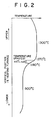
- Fig. 2 is a graph illustrating a temperature distribution in the vertical direction in the furnace body 2 of the heating furnace 1 of the apparatus shown in Fig. 1, used in the method of the present invention. As shown in Fig.
- the crucible 9 was positioned by means of the crucible supporting shaft 6 in the first temperature region of about 1,300°C of the furnace body 2 of the heating furnace 1, and the above-mentioned alloy material in the crucible 9 was heated at a temperature of 1,300°C for one hour to totally melt the alloy material. Then, the crucible 9 was moved downwardly in the vertical direction at a speed of 1.5 mm/minute in the second temperature region of from 1,270 to 1,180°C of the furnace body 2, in which a temperature decreased at a temperature gradient of 45°C/cm, to solidify and crystallize the resultant melt 10 of the alloy material in the crucible 9.
- the resultant solidified mass 10′ of the alloy material in the crucible 9 was slowly cooled in the third temperature region of about 800°C of the furnace body 2 while continuing the above-mentioned movement of the crucible 9, whereby an alloy rod having a diameter of 32 mm and having giant magnetostriction as represented by an amount of magnetostriction of at least 10 ⁇ 3, which comprised a single-crystal structure having the ⁇ 112> orientation, was manufactured at a high frequency without causing cracks.
Abstract
A method for manufacturing an alloy rod having giant magnetostriction, which comprises the steps of: supplying a granular or flaky alloy material, which comprises at least two rare earth metals including terbium and dysprosium and at least one transition metal, into a tubular crucible in an inert gas atmosphere kept under a pressure of from 0.2 to 10 atm., arranged in a vertical cylindrical heating furnace; totally melting the alloy material in the crucible in the heating furnace; and then vertically moving any one of the crucible and the heating furnace at a speed of from 0.1 to 5.0 mm/minute in a temperature region of from 1,270 to 1,180°C of the heating furnace, in which a temperature decreases at a temperature gradient of from 10 to 100°C/cm, to solidify and crystallize the resultant melt of the alloy material in the crucible in a lower portion of the heating furnace, thereby manufacturing an alloy rod having giant magnetostriction, which comprises a single-crystal structure or a unidirectional-solidification structure consistent with the axial line thereof.
Description
- As far as we know, there are available the following prior art documents pertinent to the present invention:
- (1) Japanese Patent Provisional Publication No.53-64,798 dated June 9, 1978; and
- (2) Japanese Patent Provisional Publication No.62-109,946 dated May 21, 1987.
- The contents of the prior art disclosed in the above-mentioned prior art documents will be discussed hereafter under the heading of the "BACKGROUND OF THE INVENTION".
- The present invention relates to a method for manufacturing an alloy rod having giant magnetostriction.
- An alloy rod having giant magnetostriction such as an amount of magnetostriction of, for example, at least 10⁻³ is now attracting the general attention as a material for elements of an electric audio converter, a vibrator, an actuator and the like, and industrialization thereof is underway. The alloy rod having such giant magnetostriction is usually manufactured by heat-treating a rod-shaped alloy material at a temperature slightly lower than the melting point thereof, or totally melting a granular or flaky alloy material and then solidifying the resultant melt of the alloy material into a rod shape.
- An alloy comprising at least two rare earth metals including terbium (Tb) and dysprosium (Dy) and at least one transition metal is available as an alloy material for the alloy rod having such giant magnetostriction. As the above-mentioned alloy, an alloy having the following chemical composition is known in the product name of "Terfenol":
TbXDyYFeZ
where, X, Y and Z are ratios of the number of atoms, taking respectively the following values:
X : from 0.25 to 0.35,
Y : from 0.60 to 0.80, and
Z : from 1.5 to 2.0. - For the manufacture of an alloy rod having giant magnetorstiction, the following methods are known:
- (1) A method for manufacturing an alloy rod having giant magnetostriction, disclosed in Japanese Patent Provisional Publication No.53-64,798 dated June 9, 1978, which comprises the steps of:
subjecting a rod-shaped alloy material having a chemical composition comprising Tb0.28Dy0.72Fe₂ to a heat treatment in an inert gas atmosphere, which heat treatment comprises heating said alloy material to a temperature slightly lower than the melting point thereof by means of an annular heater stationarily arranged so as to surround said alloy material while moving said alloy material in the axial direction thereof, thereby manufacturing an alloy rod having giant magnetostriction (hereinafter referred to as the "prior art 1"). - (2) A method for manufacturing an alloy rod having giant magnetostriction, disclosed in Japanese Patent Provisional Publication No.62-109,946 dated May 21, 1987, which comprises the steps of:
receiving a rod-shaped alloy material having a chemical composition comprising TbXDy1-XFe1.5-2.0 (X being from 0.27 to 0.35) into a chamber made of quarts in an inert gas atmosphere; moving an annular high-frequency heating coil, arranged so as to surround said chamber, from the lower end toward the upper end of said chamber to heat said rod-shaped alloy material in said chamber in the circumferential direction thereof; continuously moving said heating from the lower end toward the upper end of said alloy material in the axial direction thereof to locally and sequentially melt said alloy material in the axial direction thereof; and then, locally and sequentially solidifying the resultant molten section of said alloy material in said chamber, thereby manufacturing an alloy rod having giant magnetostriction (hereinafter referred to as the "prior art 2"). - (3) A method, based on the conventional Bridgman method, for manufacturing an alloy rod having giant magnetostriction, which comprises the steps of:
supplying a granular or flaky alloy material, comprising at least two rare earth metals including terbium and dysprosium and at least one transition metal, into a crucible in an inert gas atmosphere placed in a vertical cylindrical heating furnace; totally melting said alloy material in said crucible in said heating furnace; and then, vertically moving any one of said crucible and said heating furnace to solidify and crystallize the resultant melt of said alloy material in said crucible at a lower portion of said heating rurnace, thereby manufacturing an alloy rod having giant magnetostriction (hereinafter referred to as the "prior art 3"). - The above-mentioned prior art 1 has the following problems: A rod-shaped alloy material having a chemical composition comprising TbXDyYFeZ is brittle in general. Therefore, an alloy rod having giant magnetostriction manufactured by applying a heat treatment to the rod-shaped alloy material having such a chemical composition is also brittle and easily cracks. In addition, the heat treatment applied to the rod-shaped alloy material requires a long period of time, thus leading to a low manufacturing efficiency.
- The above-mentioned
prior art 2 has the follow-ing problems: When locally and sequentially melting the rod-shaped alloy material in the axial direction thereof and then locally and sequentially solidifying the resultant molten section of the alloy material, the molten section is held between the not yet melted alloy material and the melted and solidified alloy rod under the effect of surface tention of the molten section. However, the TbXDyYFeZ alloy in a molten state has only a small surface tention, with a high density. When a diameter of the alloy material is large, therefore, the molten section between the not yet melted alloy material and the melted and solidified alloy rod falls down in the form of drops, thus making it impossible to manufacture the alloy rod. According to the experience of the inventors, a diameter of the alloy rod capable of being stably manufactured in accordance with this method is 10 mm on the maximum even when adjusting the frequency and the output of the high-frequency heating coil for melting the alloy material. There is at present a demand for an alloy rod having giant magnetostriction, which has a large diameter of over 10 mm, for use as elements for an electric audio converter, a vibrator, an actuator and the like having a large output. However, such a large-diameter alloy rod having giant magnetostriction cannot be manufactured by theprior art 2. - The above-mentioned
prior art 3 has the following problems: According to theprior art 3, it is possible to manufacture an alloy rod having a large diameter of over 10 mm. However, in order to manufacture an alloy rod having giant magnetostriction from an alloy material comprising at least two rare earth metals including terbium and dysprosium and at least one transition metal in accordance with theprior art 3, it is necessary to solidify and crystallize the melt of the alloy material in the crucible so as to achieve a single-crystal structure or a unidirectional-solidification structure consistent with the axial line thereof. However, it is not necessarily easy to solidify and crystallize the melt of the alloy material in the crucible so as to achieve a single-crystal structure or a unidirectional-solidification structure consistent with the axial line thereof. According to theprior art 3, therefore, it is difficult to stably manufacture an alloy rod having giant magnetostriction at a high efficiency. - Under such circumstances, there is a strong demand for the development of a method for manufacturing stably at a high efficiency an alloy rod having a large diameter of over 10 mm and giant magnetostriction without causing cracks, but such a method has not as yet been proposed.
- An object of the present invention is therefore to provide a method for manufacturing stably at a high efficiency an alloy rod having a large diameter of over 10 mm and giant magnetostriction without causing cracks.
- In accordance with one of the features of the present invention, there is provided a method for manufacturing an alloy rod having giant magnetostriction, which comprises the steps of:
supplying a granular or flaky alloy material, which comprises at least two rare earth metals including terbium and dysprosium and at least one transition metal, into a tubular crucible in an inert gas atmosphere, arranged in a substantially vertical cylindrical heating furnace;
totally melting said alloy material in said crucible in said heating furnace, and then vertically moving any one of said crucible and said heating furnace to solidify and crystallize the resultant melt of said alloy material in said crucible in a lower portion of said heating furnace, thereby manufacturing an alloy rod having giant magnetostriction, which comprises a single-crystal structure or a unidirectional-solidification structure consistent with the axial line thereof;
characterized in that:
said inert gas atmosphere in said crucible is kept under a pressure within a range of from 0.2 to 10 atm.; and
any one of said crucible and said heating furnace is moved at a speed within a range of from 0.1 to 5.0 mm/minute in a temperature region of from 1,270 to 1,180°C of said heating furnace, in which a temperature decreases at a temperature gradient within a range of from 10 to 100°C/cm, to crystallize said melt of said alloy material in said crucible. -
- Fig. 1 is a schematic descriptive view illustrating an embodiment of the apparatus used in the method of the present invention; and
- Fig. 2 is a graph illustrating a temperature distribution in the vertical direction in a heating furnace of the apparatus shown in Fig. 1, used in the method of the present invention.
- From the above-mentioned point of view, extensive studies were carried out to develop a method for manufacturing stably at a high efficiency an alloy rod having a large diameter of over 10 mm and giant magnetostriction without causing cracks. As a result, the following findings were obtained: It is possible to stably manufacture at a high efficiency without causing cracks an alloy rod having giant magnetostriction, which comprises a single-crystal structure or a unidirectional-solidification structure consistent with the axial line thereof, by supplying a grannular or a flaky alloy material, which comprises at least two rare earth metals including terbium and dysprosium and at least one transition metal, into a tubular crucible in an inert gas atmosphere kept under a pressure of from 0.2 to 10 atm., arranged in a vertical cylindrical heating furnace; totally melting said alloy material in said crucible in said heating furnace; and then vertically moving any one of said crucible and said heating furnace at a speed of from 0.1 to 5 mm/minute in a temperature region of from 1,270 to 1,180°C of said heating furnace, in which a temperature decreases at a temperature gradient of from 10 to 100°C/cm, to solidify and crystallize the resultant melt of said alloy material in said crucible in a lower portion of said heating furnace.
- The present invention was made on the basis of the above-mentioned findings. Now, the method of the present invention for manufacturing an alloy rod having giant magnetostriction is described with reference to the drawings.
- Fig. 1 is a schematic descriptive view illustrating an embodiment of the apparatus used in the method of the present invention. As shown in Fig. 1, a stationarily arranged cylindrical heating furnace 1 comprises a substantially vertical
cylindrical furnace body 2, amain heater 3 arranged so as to surround an upper portion of thefurnace body 2, and twosub-heaters 4 arranged directly below themain heater 3 so as to surround a lower portion of thefurnace body 2. Each of themain heater 3 and thesub-heaters 4 comprises, for example, an electric-resistance heater. Atubular crucible 9 made of ceramics is supported substantially vertically in thefurance body 2 of the heating furnace 1 by means of acrucible support 5 made, for example, of boron nitride fitted to the upper end of a substantially verticalcrucible supporting shaft 6. Thecrucible supporting shaft 6 projects downwardly through a sealingmember 7 from the lower end of thefurance body 2, and is vertically movable by means of a driving mechanism not shown. Athermocouple 8 for measuring a temperature in the interior of thefurnace body 2 is substantially vertically inserted into the interior of an upper portion of thefurnace body 2, which is surrounded by themain heater 3. The upper end of thefurance body 2 is capable of being opened and closed by means of a cover not shown. - A granular or flaky alloy material, comprising at least two rare earth metals including terbium and dysprosium and at least one transition metal, is supplied into the
crucible 9. Thecrucible 9 thus supplied with the alloy material is positioned by means of thecrucible supporting shaft 6 in the upper portion of thefurnace body 2 of the heating furnace 1, which is surrounded by themain heater 3. Then, thecrucible 9 is heated by means of themain heater 3 to totally melt the alloy material in thecrucible 9. Then, thecrucible 9 is downwardly moved in the vertical direction by the action of thecrucible supporting shaft 6 to solidify and crystallize theresultant melt 10 of the alloy material in thecrucible 9 at a position in thefurnace body 2, which corresponds to a lower portion of themain heater 3. An alloy rod is thus manufactured. In place of arranging the heating furnace 1 in a stationary manner and moving thecrucible 9 downwardly in the vertical direction, thecrucible 9 may be arranged in a stationary manner and the heating furnace 1 may be moved upwardly in the vertical direction. - In order that the thus manufactured alloy rod has giant magnetostriction, the alloy rod should have a single-crystal structure or a unidirectional-solidification structure consistent with the axial line thereof. The conditions for the method of the present invention for stably manufacturing, at a high efficiency without causing cracks, the alloy rod having giant magnetostriction, which comprises a single-crystal structure or a unidirectional-solidification structure consistent with the axial line thereof, are described below.
- A temperature gradient in the temperature region, in which the
melt 10 of the alloy material comprising at least two rare earth metals including terbium and dysprosium and at least one transition metal is crystallized, and a moving speed of any one of thecrucible 9 and the heating furnace 1 in the above-mentioned temperature region, exert an important effect on the crystal structure of a solidifiedmass 10′ of the alloy material. A crystal lization start temperature of themelt 10 of the alloy material comprising at least two rare earth metals including terbium and dysprosium and at least one transition metal is within the range of from about 1,225 to about 1,245°C, and a secondary peritectic temperature of themelt 10 is about 1,185°C. In the present invention, therefore, a downward temperature gradient in the temperature region of from 1,270 to 1,180°C of thefurnace body 2 of the heating furnace 1 is limited within a range of from 10 to 100°C/cm, and a moving speed of any one of thecrucible 9 and the heating furnace 1 in the temperature region, in which a temperature decreases at such a temperature gradient, is limited within a range of from 0.1 to 5.0 mm/minute. - With a temperature gradient of under 10°C/cm in the above-mentioned temperature region, the moving speed of any one of the
crucible 9 and the heating furnace 1 must be an extra-low speed of under 0.1 mm/minute, thus deteriorating productivity and making it impossible to manufacture an alloy rod at a high efficiency. Imparting a temperature gradient of over 100°C/cm to the above-mentioned temperature region is, on the other hand, difficult from equipment considerations. With a moving speed of under 0.1 mm/minute of any one of thecrucible 9 and the heating furnace 1 in the above-mentioned temperature region, productivity is low and an alloy rod cannot be manufactured at a high efficiency, as described above. With a moving speed of over 5.0 mm/minute of any one of thecrucible 9 and the heating furnace 1 in the above-mentioned temperature region, on the other hand, it is difficult for the solidifiedmass 10′ of the alloy material in thecrucible 9 to have a single-crystal structure or a unidirectional-solidification structure consistent with the axial line thereof. The temperature region of thefurnace body 2 of the heating furnace 1, in which a temperature decreases at the above-mentioned temperature gradient, is formed at a position in thefurnace body 2, which corresponds to a lower portion of themain heater 3. - An alloy comprising at least two rare earth metals including terbium and dysprosium and at least one transition metal is very active. Therefore, the interior of the
crucible 9, in which the granular or flaky alloy material comprising such an active alloy is supplied and melted, and themelt 10 thereof is solidified, should be maintained in an inert gas atmosphere kept under a pressure within a range of from 0.2 to 10 atm. In the apparatus shown in Fig. 1, the interior of the heating furance 1 is maintained in an inert gas atmosphere kept under a pressure within the above-mentioned range. With a pressure of the inert gas atmosphere of under 0.2 atm., volatile dysprosium in themelt 10 of the alloy material evaporates, thus causing the problem of changes in the chemical composition of the solidifiedmass 10′. A pressure of the inert gas atmosphere of over 10 atm., on the other hand, causes safety problems in operation. - As shown in Fig. 1, at least one
sub-heater 4 should preferably be arranged directly below themain heater 3 so as to surround the lower portion of thefurnace body 2. By thus arranging at least onesub-heater 4, it is possible to prevent occurrence of cracks in the solidifiedmass 10′ during solidification of themelt 10 of the alloy material in thecrucible 9, melted by means of themain heater 3. - A preferable chemical composition of the alloy material for manufacturing an alloy rod having giant magnetostriction is as follows:
TbXDyYFeZ
where, X, Y, and Z are ratios of the number of atoms, taking respectively the following values:
X : from 0.25 to 0.35,
Y : from 0.60 to 0.80, and
Z : from 1.5 to 2.0. - A bottom 9a of the
crucible 9 should preferably be formed into an inverted cone shape having an angle within a range of from 30° to 100°. When the bottom 9a of thecrucible 9 is thus formed into an inverted cone shape, it is possible to promote production of crystal nuclei and growth of a single-crystal structure. An angle of under 30° of the inverted cone shape of the bottom 9a leads to an unnecessarilylong bottom 9a. An inverted cone-shaped solidifiedmass 10′ solidified in such a long inverted cone-shapedbottom 9a has to be trimmed away. An angle of under 30° of the inverted cone shape of the bottom 9a therefore increases the amount of trimming of the solidifiedmass 10′, thus leading to a lower product yield. An angle of over 100° of the inverted cone shape of the bottom 9a, on the other hand, makes it impossible to promote production of crystal nuclei and growth of a single-crystal structure, as described above. - It is desirable to form an elongated vertical recess not shown having, for example, a diameter of from 1 to 5 mm and a depth of from 10 to 50 mm, on the bottom 9a of the
crucible 9, formed into the inverted cone shape, and to fill the thus formed recess with a seed crystal having the same chemical composition as that of the alloy material and the <111> orientation or the <112> orientation. Filling the recess with the seed crystal promotes growth of crystals having the <111> orientation or the <112> orientation excellent in magnetostrictive property in the alloy rod. When themelt 10 of the alloy material comprising at least two rare earth metals including terbium and dysprosium and at least one transition metal is solidified, crystals having the <112> orientation preferentially grow. The crystals having the <112> orientation have a magnetostrictive property closely approximating to that of crystals having the <111> orientation, which have the most excellent magnetostrictive property. Therefore, an alloy rod having almost satisfactory giant magnetostriction is available without using the above-mentioned seed crystal. - An alloy comprising at least two rare earth metals including terbium and dysprosium and at least one transition metal is very active as described above. Therefore, the
crucible 9, in which the granular or flaky alloy material comprising such an acitive alloy is melted and themelt 10 of the alloy material is solidified, should preferably be formed of ceramics mainly comprising at least one of quartz (SiO₂), pyrolytic boron nitride (P-BN), calcium oxide (CaO), yttrium oxide (Y₂O₃), zirconium oxide (ZrO₂), aluminum oxide (Al₂O₃) and magnesium oxide (MgO). - As described above, the granular or flaky alloy material, comprising at least two rare earth metals including terbium and dysprosium and at least one transition metal, is supplied into the
tubular crucible 9 in an inert gas atmosphere kept under a pressure of from 0.2 to 10 atm., arranged in thefurnace body 2 of the heating furnace 1. The alloy material in thecrucible 9 is totally melted in thefurnace body 2. Then, thecrucible 9 is downwardly moved in the vertical direction at a speed of from 0.1 to 5 mm/minute in a temperature region of from 1,270 to 1,180°C of thefurnace body 2, in which a temperature decreases at a temperature gradient of from 10 to 100°C/cm, to solidify and crystallize theresultant melt 10 of the alloy material in thecrucible 9 at a position in thefurance body 2, which corresponds to the lower portion of themain heater 3. As a result, the solidifiedmass 10′ of the alloy material has a single-crystal structure or a unidirectional-solidification structure consistent with the axial line thereof, thus an alloy rod having giant magnetostriction is manufactured. - Now, the method of the present invention for manufacturing an alloy rod having giant magnetostriction is described more in detail by means of an example.
- An alloy rod having giant magnetostriction was manufactured as follows with the use of the apparatus as shown in Fig. 1. The
crucible 9 made of ceramics mainly comprising pyrolytic boron nitride (P-BN), having the bottom 9a formed into an inverted cone shape with an angle of 60°, was placed on thecrucible support 5 of thecrucible supporting shaft 6. Thecrucible 9 had the following dimensions:
Inside diameter of the crucible 9 : 32 mm,
Outside diameter of the crucible 9 : 34 mm, and
Height of the crucible 9 : 230 mm. - The interior of the
furnace body 2 of the heating furnace 1 was maintained in an argon gas atmosphere kept under a pressure of 2 atm., and a flaky alloy material having a chemical composition comprising Tb0.3Dy0.7Fe1.9 was supplied into thecrucible 9. - Temperature regions having respective temperature distributions as described below were formed in the
furnace body 2 of the heating furnace 1 by means of themain heater 3 arranged so as to surround the upper portion of thefurnace body 2 and the twosub-heaters 4 arranged directly below themain heater 3 so as to surround the lower portion of thefurnace body 2. Fig. 2 is a graph illustrating a temperature distribution in the vertical direction in thefurnace body 2 of the heating furnace 1 of the apparatus shown in Fig. 1, used in the method of the present invention. As shown in Fig. 2, a first temperature region of about 1,300°C for melting the alloy material, and a second temperature region of from 1,270 to 1,180°C, directly below the first temperature region, in which a temperature decreases at a temperature gradient of 45°C/cm, for solidifying and crystallizing themelt 10 of the alloy material, were formed by means of themain heater 3 in the upper portion of the interior of thefurnace body 2 of the heating furnace 1. Furthermore, a third temperature region of about 800°C, directly below the second temperature region, for preventing occurrence of cracks in the solidifiedmass 10′ during solidification of themelt 10 of the alloy material, was formed by means of the twosub-heaters 4 in the lower portion of the interior of thefurnace body 2 of the heating furnace 1. The temperature in the upper portion of the interior of thefurnace body 2 of the heating furnace 1 was measured by means of thethermocouple 8 to adjust the output of themain heater 3 so that the temperature in the upper portion of the interior of thefurnace body 2 was kept at the above-mentioned temperature of about 1,300°C. - The
crucible 9 was positioned by means of thecrucible supporting shaft 6 in the first temperature region of about 1,300°C of thefurnace body 2 of the heating furnace 1, and the above-mentioned alloy material in thecrucible 9 was heated at a temperature of 1,300°C for one hour to totally melt the alloy material. Then, thecrucible 9 was moved downwardly in the vertical direction at a speed of 1.5 mm/minute in the second temperature region of from 1,270 to 1,180°C of thefurnace body 2, in which a temperature decreased at a temperature gradient of 45°C/cm, to solidify and crystallize theresultant melt 10 of the alloy material in thecrucible 9. Then, the resultant solidifiedmass 10′ of the alloy material in thecrucible 9 was slowly cooled in the third temperature region of about 800°C of thefurnace body 2 while continuing the above-mentioned movement of thecrucible 9, whereby an alloy rod having a diameter of 32 mm and having giant magnetostriction as represented by an amount of magnetostriction of at least 10⁻³, which comprised a single-crystal structure having the <112> orientation, was manufactured at a high frequency without causing cracks. - According to the method of the present invention, as described above in detail, it is possible to stably manufacture at a high efficiency an alloy rod having a large diameter of over 10 mm and giant magnetostriction without causing cracks, thus providing industrially useful effects.
Claims (8)
1. A method for manufacturing an alloy rod having giant magnetostriction, which comprises the steps of:
supplying a granular or flaky alloy material, which comprises at least two rare earth metals including terbium and dysprosium and at least one transition metal, into a tubular crucible in an inert gas atmosphere, arranged in a substantially vertical cylindrical heating furnace;
totally melting said alloy material in said crucible in said heating furnace, and then vertically moving any one of said crucible and said heating furnace to solidify and crystallize the resultant melt of said alloy material in said crucible in a lower portion of said heating furnace, thereby manufacturing an alloy rod having giant magnetostriction, which comprises a single-crystal structure or a unidirectional-solidification structure consistent with the axial line thereof;
characterized in that:
said inert gas atmosphere in said crucible is kept under a pressure within a range of from 0.2 to 10 atm.; and
any one of said crucible and said heating furnace is moved at a speed within a range of from 0.1 to 5.0 mm/minute in a temperature region of from 1,270 to 1,180°C of said heating furnace, in which a temperature descreases at a temperature gradient within a range of from 10 to 100°C/cm, to crystallize said melt of said alloy material in said crucible.
2. A method as claimed in Claim 1, wherein:
said heating furnace comprises a cylindrical furnace body, a main heater arranged so as to surround an upper portion of said furnace body, and at least one sub-heater arranged directly below said main heater so as to surround a lower portion of said furnace body.
said heating furnace comprises a cylindrical furnace body, a main heater arranged so as to surround an upper portion of said furnace body, and at least one sub-heater arranged directly below said main heater so as to surround a lower portion of said furnace body.
3. A method as claimed in Claim 1, wherein:
said heating furnace is stationarily arranged, and said crucible is downwardly moved in the vertical direction.
said heating furnace is stationarily arranged, and said crucible is downwardly moved in the vertical direction.
4. A method as claimed in Claim 1, wherein:
said crucible is stationarily arranged, and said heating furnace is upwardly moved in the vertical direction.
said crucible is stationarily arranged, and said heating furnace is upwardly moved in the vertical direction.
5. A method as claimed in Claim 1, wherein:
said alloy material has a chemical composition comprising:
TbXDyYFeZ
where, X, Y and Z are ratios of the number of atoms, taking respectively the following values:
X : from 0.25 to 0.35,
Y : from 0.60 to 0.80, and
Z : from 1.5 to 2.0.
said alloy material has a chemical composition comprising:
TbXDyYFeZ
where, X, Y and Z are ratios of the number of atoms, taking respectively the following values:
X : from 0.25 to 0.35,
Y : from 0.60 to 0.80, and
Z : from 1.5 to 2.0.
6. A method as claimed in Claim 1, wherein:
a bottom of said crucible is formed into an inverted cone shape having an angle within a range of from 30° to 100°.
a bottom of said crucible is formed into an inverted cone shape having an angle within a range of from 30° to 100°.
7. A method as claimed in Claim 6, wherein:
an elongated vertical recess is formed on said bottom of said crucible, which bottom is formed into said inverted cone shape, and said recess is filled with a seed crystal having the same chemical composition as that of said alloy material and having the <111> orientation or the <112> orientation.
an elongated vertical recess is formed on said bottom of said crucible, which bottom is formed into said inverted cone shape, and said recess is filled with a seed crystal having the same chemical composition as that of said alloy material and having the <111> orientation or the <112> orientation.
8. A method as claimed in Claim 1, wherein:
said crucible is formed of ceramics mainly comprising at least one of quartz (SiO₂), pyrolytic boron nitride (P-BN), calcium oxide (CaO), yttrium oxide (Y₂O₃), zirconium oxide (ZrO₂), aluminum oxide (Al₂O₃) and magnesium oxide (MgO).
said crucible is formed of ceramics mainly comprising at least one of quartz (SiO₂), pyrolytic boron nitride (P-BN), calcium oxide (CaO), yttrium oxide (Y₂O₃), zirconium oxide (ZrO₂), aluminum oxide (Al₂O₃) and magnesium oxide (MgO).
Applications Claiming Priority (2)
| Application Number | Priority Date | Filing Date | Title |
|---|---|---|---|
| JP168454/89 | 1989-06-30 | ||
| JP1168454A JPH062635B2 (en) | 1989-06-30 | 1989-06-30 | Giant magnetostrictive alloy rod manufacturing method |
Publications (1)
| Publication Number | Publication Date |
|---|---|
| EP0405362A1 true EP0405362A1 (en) | 1991-01-02 |
Family
ID=15868409
Family Applications (1)
| Application Number | Title | Priority Date | Filing Date |
|---|---|---|---|
| EP90111888A Withdrawn EP0405362A1 (en) | 1989-06-30 | 1990-06-22 | Method for manufacturing alloy rod having giant magnetostriction |
Country Status (3)
| Country | Link |
|---|---|
| US (1) | US5067551A (en) |
| EP (1) | EP0405362A1 (en) |
| JP (1) | JPH062635B2 (en) |
Cited By (6)
| Publication number | Priority date | Publication date | Assignee | Title |
|---|---|---|---|---|
| EP0509628A1 (en) * | 1991-02-05 | 1992-10-21 | Kabushiki Kaisha Toshiba | Magnetostrictive alloys, preparation and uses |
| EP0678585A1 (en) * | 1994-04-19 | 1995-10-25 | TDK Corporation | Preparation of magnetostrictive material |
| CN1045230C (en) * | 1994-01-29 | 1999-09-22 | 冶金工业部钢铁研究总院 | Method for prodn. of super magnetostrictive rare-earth alloyed iron rod |
| US6273965B1 (en) | 1996-10-18 | 2001-08-14 | Iowa State University Research Foundation, Inc. | Magnetostrictive materials and method for improving AC characteristics in same |
| CN103121852A (en) * | 2012-12-12 | 2013-05-29 | 上海电气钠硫储能技术有限公司 | Magnesia crucible for synthesizing sodium-sulfur cell solid electrolyte and preparation method of magnesia crucible |
| DE10196450B3 (en) * | 2000-07-21 | 2014-11-06 | Continental Automotive Systems, Inc. ( n. d. Ges. d. Staates Delaware ) | Metallurgical and mechanical compensation of the temperature behavior of terbium-based rare earth magnetostrictive alloys |
Families Citing this family (7)
| Publication number | Priority date | Publication date | Assignee | Title |
|---|---|---|---|---|
| GB2393042B (en) * | 2002-09-11 | 2005-09-28 | Black & Decker Inc | Electrical extension lead |
| EP0556751B1 (en) * | 1992-02-15 | 1998-06-10 | Santoku Metal Industry Co., Ltd. | Alloy ingot for permanent magnet, anisotropic powders for permanent magnet, method for producing same and permanent magnet |
| US7294199B2 (en) * | 2004-06-10 | 2007-11-13 | Sumitomo Electric Industries, Ltd. | Nitride single crystal and producing method thereof |
| WO2006116227A2 (en) * | 2005-04-22 | 2006-11-02 | Siemens Water Technologies Holding Corp. | Vibratory mixer |
| GB201313849D0 (en) * | 2013-08-02 | 2013-09-18 | Castings Technology Internat | Producing a metal object |
| GB201319671D0 (en) | 2013-11-07 | 2013-12-25 | Ebner Ind Ofenbau | Controlling a temperature of a crucible inside an oven |
| JP6122882B2 (en) | 2015-01-29 | 2017-04-26 | 日本高周波鋼業株式会社 | Magnetostrictive member and manufacturing method thereof |
Citations (3)
| Publication number | Priority date | Publication date | Assignee | Title |
|---|---|---|---|---|
| US4308474A (en) * | 1979-11-14 | 1981-12-29 | The United States Of America As Represented By The Secretary Of The Navy | Rare earth-iron magnetostrictive materials and devices using these materials |
| EP0221468A2 (en) * | 1985-10-28 | 1987-05-13 | Iowa State University Research Foundation, Inc. | Method of forming magnetostrictive rods from rare earth-iron alloys |
| EP0282059A2 (en) * | 1987-03-13 | 1988-09-14 | Iowa State University Research Foundation, Inc. | Continuous method for manufacturing grain-oriented magnetostrictive bodies |
Family Cites Families (5)
| Publication number | Priority date | Publication date | Assignee | Title |
|---|---|---|---|---|
| JPS5364798A (en) * | 1976-11-19 | 1978-06-09 | Shingijutsu Kaihatsu Jigyodan | Electric magntostrictive convertor |
| GB2051607B (en) * | 1979-07-05 | 1983-06-29 | Philips Electronic Associated | Method of making monocrystalline ternary semiconductor material |
| JPS59158574A (en) * | 1983-03-01 | 1984-09-08 | Toshiba Corp | Control element for minute displacement |
| JPS6241792A (en) * | 1985-08-20 | 1987-02-23 | Fujitsu Ltd | Production of semiconductor single crystal |
| JPH01242480A (en) * | 1988-03-25 | 1989-09-27 | Tokin Corp | Apparatus for producing single crystal |
-
1989
- 1989-06-30 JP JP1168454A patent/JPH062635B2/en not_active Expired - Lifetime
-
1990
- 1990-06-18 US US07/539,603 patent/US5067551A/en not_active Expired - Fee Related
- 1990-06-22 EP EP90111888A patent/EP0405362A1/en not_active Withdrawn
Patent Citations (3)
| Publication number | Priority date | Publication date | Assignee | Title |
|---|---|---|---|---|
| US4308474A (en) * | 1979-11-14 | 1981-12-29 | The United States Of America As Represented By The Secretary Of The Navy | Rare earth-iron magnetostrictive materials and devices using these materials |
| EP0221468A2 (en) * | 1985-10-28 | 1987-05-13 | Iowa State University Research Foundation, Inc. | Method of forming magnetostrictive rods from rare earth-iron alloys |
| EP0282059A2 (en) * | 1987-03-13 | 1988-09-14 | Iowa State University Research Foundation, Inc. | Continuous method for manufacturing grain-oriented magnetostrictive bodies |
Non-Patent Citations (1)
| Title |
|---|
| METALLURGICAL TRANSACTIONS A, vol. 18A, February 1987, pages 223-231, New York, US; J.D. VERHOEVEN et al.: "The growth of single crystal terfenol-D crystals" * |
Cited By (10)
| Publication number | Priority date | Publication date | Assignee | Title |
|---|---|---|---|---|
| EP0509628A1 (en) * | 1991-02-05 | 1992-10-21 | Kabushiki Kaisha Toshiba | Magnetostrictive alloys, preparation and uses |
| US5336337A (en) * | 1991-02-05 | 1994-08-09 | Kabushiki Kaisha Toshiba | Magnetrostrictive materials and methods of making such materials |
| US5527398A (en) * | 1991-02-05 | 1996-06-18 | Kabushiki Kaisha Toshiba | Magnetostrictive materials and methods of making such materials |
| CN1045230C (en) * | 1994-01-29 | 1999-09-22 | 冶金工业部钢铁研究总院 | Method for prodn. of super magnetostrictive rare-earth alloyed iron rod |
| EP0678585A1 (en) * | 1994-04-19 | 1995-10-25 | TDK Corporation | Preparation of magnetostrictive material |
| US5529745A (en) * | 1994-04-19 | 1996-06-25 | Tdk Corporation | Preparation of magnetostrictive material |
| US6273965B1 (en) | 1996-10-18 | 2001-08-14 | Iowa State University Research Foundation, Inc. | Magnetostrictive materials and method for improving AC characteristics in same |
| DE10196450B3 (en) * | 2000-07-21 | 2014-11-06 | Continental Automotive Systems, Inc. ( n. d. Ges. d. Staates Delaware ) | Metallurgical and mechanical compensation of the temperature behavior of terbium-based rare earth magnetostrictive alloys |
| CN103121852A (en) * | 2012-12-12 | 2013-05-29 | 上海电气钠硫储能技术有限公司 | Magnesia crucible for synthesizing sodium-sulfur cell solid electrolyte and preparation method of magnesia crucible |
| CN103121852B (en) * | 2012-12-12 | 2014-07-16 | 上海电气钠硫储能技术有限公司 | Magnesia crucible for synthesizing sodium-sulfur cell solid electrolyte and preparation method of magnesia crucible |
Also Published As
| Publication number | Publication date |
|---|---|
| JPH0337182A (en) | 1991-02-18 |
| US5067551A (en) | 1991-11-26 |
| JPH062635B2 (en) | 1994-01-12 |
Similar Documents
| Publication | Publication Date | Title |
|---|---|---|
| EP0068021B1 (en) | The method and apparatus for forming and growing a single crystal of a semiconductor compound | |
| US6027563A (en) | Method and apparatus for the oriented solidification of molten silicon to form an ingot in a bottomless crystallization chamber | |
| EP0405362A1 (en) | Method for manufacturing alloy rod having giant magnetostriction | |
| JP5493092B2 (en) | Method for producing gallium oxide single crystal and gallium oxide single crystal | |
| US5993545A (en) | Crucible for growing single crystals, process for making the same and use of the same | |
| US4303465A (en) | Method of growing monocrystals of corundum from a melt | |
| US4623423A (en) | Process for producing a strain-free monocrystal of a crystalline ferroelectric compound | |
| US5063986A (en) | Method for manufacturing alloy rod having giant magnetostriction | |
| JP7072146B2 (en) | Single crystal growth method for iron gallium alloy | |
| EP0322799B1 (en) | Method for producing crystalline reinforced block material of metal or the like | |
| CN1150185A (en) | Technique for preparing monocrystal of metal material | |
| JP3367069B2 (en) | Manufacturing method of giant magnetostrictive alloy rod | |
| JPH0497989A (en) | Production of single crystal and pulling up device for single crystal | |
| JP2022146327A (en) | MANUFACTURING METHOD OF FeGa ALLOY SINGLE CRYSTAL | |
| US6497762B1 (en) | Method of fabricating crystal thin plate under micro-gravity environment | |
| RU2040599C1 (en) | Method for production of single crystals of rare-earth metal borides | |
| JP2022146328A (en) | MANUFACTURING METHOD OF FeGa ALLOY SINGLE CRYSTAL | |
| RU2072399C1 (en) | Method of preparing monocrystals of refractory substances | |
| JP2022020187A (en) | METHOD FOR PRODUCING FeGa ALLOY SINGLE CRYSTAL | |
| US4431599A (en) | Method for the melting and solidification of silicon | |
| JPH0380180A (en) | Device for producing single crystal | |
| RU2199614C1 (en) | Method of growing crystals | |
| JP3849004B2 (en) | Method for producing rapidly solidified bulk amorphous alloy material | |
| CS264935B1 (en) | Treatment of growth conditions and growth sapphire modified by kyropouls method | |
| JP2997761B2 (en) | Method for producing rhenium diboride single crystal |
Legal Events
| Date | Code | Title | Description |
|---|---|---|---|
| PUAI | Public reference made under article 153(3) epc to a published international application that has entered the european phase |
Free format text: ORIGINAL CODE: 0009012 |
|
| 17P | Request for examination filed |
Effective date: 19900719 |
|
| AK | Designated contracting states |
Kind code of ref document: A1 Designated state(s): DE FR GB SE |
|
| 17Q | First examination report despatched |
Effective date: 19921014 |
|
| STAA | Information on the status of an ep patent application or granted ep patent |
Free format text: STATUS: THE APPLICATION IS DEEMED TO BE WITHDRAWN |
|
| 18D | Application deemed to be withdrawn |
Effective date: 19940216 |