EP0403752A2 - Device generating fade-in, fade-out effects - Google Patents
Device generating fade-in, fade-out effects Download PDFInfo
- Publication number
- EP0403752A2 EP0403752A2 EP90107145A EP90107145A EP0403752A2 EP 0403752 A2 EP0403752 A2 EP 0403752A2 EP 90107145 A EP90107145 A EP 90107145A EP 90107145 A EP90107145 A EP 90107145A EP 0403752 A2 EP0403752 A2 EP 0403752A2
- Authority
- EP
- European Patent Office
- Prior art keywords
- counter
- video signal
- arrangement
- line
- pixel
- Prior art date
- Legal status (The legal status is an assumption and is not a legal conclusion. Google has not performed a legal analysis and makes no representation as to the accuracy of the status listed.)
- Granted
Links
Images

Classifications
-
- H—ELECTRICITY
- H04—ELECTRIC COMMUNICATION TECHNIQUE
- H04N—PICTORIAL COMMUNICATION, e.g. TELEVISION
- H04N5/00—Details of television systems
- H04N5/222—Studio circuitry; Studio devices; Studio equipment
- H04N5/262—Studio circuits, e.g. for mixing, switching-over, change of character of image, other special effects ; Cameras specially adapted for the electronic generation of special effects
- H04N5/265—Mixing
Definitions
- the invention relates to an arrangement for generating fade-in and fade-out effects in video devices whose image signals are digitally processed.
- the object of the invention is therefore to provide an arrangement for showing / hiding scenes in video recordings which enables a wide variety of applications, the structure of which is simple, universally applicable and inexpensive for use in video recorders or video cameras from the consumer field.
- Figure 1 shows a block diagram of the arrangement according to the invention.
- the horizontal and vertical synchronizing pulses H and V, as well as a reset signal R and a clock signal CLK are fed to the timing / control module TKM.
- the timing control bus TKB carries the control signals from the timing / control module TKM to the individual components of the arrangement.
- a signal clock S1 and a control signal C1 are fed to the pixel counter PZ, a signal clock S2 and a control signal C2 are fed to the pixel counter CPZ.
- the line counters ZZ and CZZ are connected to the signal clock pulses S3 and S4 and the control signals C3 and C4.
- the counter reading BP is at the output of the controlled inverter CIP and the counter reading BZ is at the output of the controlled inverter CIZ.
- the function of the controlled inverters is controlled by the carry bit of the counter in the manner explained later.
- the counter reading AP of the pixel counter PZ and the counter reading BP of the controlled inverter CIP and the control signal C5 lead to the comparator CP.
- the meter readings AZ and BZ of the line counter ZZ and the controlled inverter CIZ are at the inputs of the comparator CZ.
- the comparator is controlled by the control signal C6.
- the output signals of the comparators CP and CZ are at the inputs of the control module KM.
- the output of this module is connected to the multiplexer M, at the inputs of which there is a video signal VI and the output signal of the generator BG.
- the output of the multiplexer M leads to the logic circuit SG, the output of which contains the processed video signal VO.
- the comparator outputs CP1 and CP2 control the control module KM, which in turn controls the multiplexer M.
- This control is carried out so that the signal of the generator BG, z. B. a predetermined gray value, is controlled when the counter reading of the pixel counter PZ is smaller than the counter reading of the pixel counter CPZ, ie when the current position of the processed video signal is to the left of the limit G1 in FIG. 2a.
- the limit G1 is specified by the pixel counter CPZ.
- the video signal is controlled accordingly if the current position of the processed video signal is to the right of G1, ie if the counter reading AP is greater than the counter reading BP.
- the control circuit C71 also activates the logic circuit SG, which ensures that the synchronization frame of the video signal is not disturbed.
- the dimensioning of the counters can be reduced by one or more bits. If e.g. B. per frame or field, the boundary G1 is shifted by 2 pixels, the lowest bit of the pixel counter PZ are neglected and the pixel counter CPZ counts only one value higher per image or field, which saves one bit in the pixel counter CPZ, and also saves a comparison bit in the comparator.
- the control unit KM drives the multiplexer (M) in such a way that the video signal is turned on when the pixel counter PZ has a smaller value than the pixel counter CPZ, i.e. if the current position of the processed video signal is to the left of G11 in Figure 2b.
- the control signal C7 activates the control module KM and gives it the working mode, i.e. the fade in or out process.
- FIGS. 2e to 2h The fading in and out from top to bottom or from bottom to top, shown in FIGS. 2e to 2h, is carried out in the same way as from left to right and vice versa, in which case the line counters ZZ and CZZ, and the corresponding comparator CZ are active.
- the pixel counter CPZ is controlled in such a way that it counts down from its upper limit value, in this case the count value in the center of the image.
- the pixel counter PZ counts up from an initial value so that it reaches the upper limit value of the pixel counter CPZ in the center of the image and then generates a carry bit and starts counting from zero.
- the carry bit controls the controlled inverter CIP, which inverts the count of the pixel counter CPZ.
- the comparator CP is influenced by the control signal C5 so that the comparison condition is reversed.
- This control causes the pixel counter to count from an initial value to the center of the image on each line and then from zero to the final value, the final value being the inverted initial value.
- the comparison takes place up to the center of the picture with the value of the pixel counter in the form that a gray value is controlled when the value is hidden, if the counter value BP of the pixel counter CPZ is smaller than the counter value AP of the pixel counter PZ, in the other case the video signal is controlled.
- the count value of the pixel counter PZ is compared with the inverted value of the pixel counter CPZ, the gray value being controlled after the center of the image if the value of the pixel counter PZ is less than or equal to the inverted value of the pixel counter CPZ, i.e. vice versa than before Middle of picture.
- FIGS. 5a and 5b show how the fade-in / fade-out options can be expanded further by means of finer subdivision (FIG. 5a) or by means of other counter limit values, so that strips of any number can be faded in or out.
- the striped fading in / out is also possible in the manner described above in the vertical direction, so that patterns according to FIGS. 6a, 6b result.
- a further advantageous embodiment of the invention results if the pixel counter CPZ is supplemented in the manner shown in FIG.
- the counter reading BP is additionally fed to a multiplexer input AM of the multiplexer MUX, at the second input BM of which an external count is present, whereby the control signal C9, which comes from the timing / control module TKM, specifies which of the two input signals at the output of the Multiplexers MUX is present.
- the output signal AMUX leads to a latch L, the output of which leads to the pixel counter CPZ. Latch L is controlled by control signal C8.
- Figure 8 serves to explain the procedure.
- the pixel counters now have a counting area that is designed in such a way that counting is carried out over 3 adjacent picture lines, first over a virtual, invisible picture (a), then over the visible area (b) and finally again over a virtual area (c ).
- the reason for this method of counting can be seen from FIG. 8.
- a diagonal border in the image area, which begins in the lower right corner, if the border is not to be specified by stored values, which is very complex and expensive, the border has to begin in the top right of the virtual image.
- a diagonal 1 is formed in the virtual area. If the diagonal is shifted to the left in the next picture or field, then the diagonal 2 in the lower right corner noticeable.
- the counter AP counts from an initial value to the end value of a line and starts again with the start value on the next line, etc.
- the pixel counter CPZ begins to count with the end value.
- the comparator CP compares both counts and controls the control module KM so that there is a signal to the multiplexer M depending on the comparison result, so that either the video signal or e.g. a gray value from the generator BG is switched through.
- the video signal is controlled when the count AP is less than BP or in the invisible range and e.g.
- the gray value is controlled when the count value AP is greater than the count value BP in the visible range.
- the pixel counter is controlled in such a way that it counts down from the upper limit value, the count value according to FIG. 8b being decreased by one count value after each line.
- the value after the first decrement here the value in the second line, is passed to a latch via a MUX and stored there. This value is used as the initial value for the next picture in the first line Image loaded into the pixel counter CPZ. This shifts the diagonal to the left by one pixel.
- the control for the multiplexer, at the second input of which an external initial value for the first line of the first image is entered, and the control for the latch are carried out from the timing / control module TKM according to the above aspects.
- the slope can be changed as desired by not increasing a pixel after each line, but increasing it by a predeterminable number of pixels after an arbitrary number of lines.
- Fade-in and fade-out processes are possible from all four corners if the counters, latches, etc. are activated accordingly.
- a second video signal can also be applied to the multiplexer M, as a result of which the described fade-in / fade-out properties can also be used for cross-fading from one image to another image.
Landscapes
- Engineering & Computer Science (AREA)
- Multimedia (AREA)
- Signal Processing (AREA)
- Studio Circuits (AREA)
- Processing Of Color Television Signals (AREA)
- Diaphragms For Electromechanical Transducers (AREA)
- Circuit Arrangement For Electric Light Sources In General (AREA)
Abstract
Description
Die Erfindung betrifft eine Anordnung zur Erzeugung von Ein- und Ausblendeffekten in Videogeräten, deren Bildsignale digital verarbeitet werden.The invention relates to an arrangement for generating fade-in and fade-out effects in video devices whose image signals are digitally processed.
Durch die immer stärkere Verbreitung von Videokameras im Hobbybereich werden auch die Anforderungen, die bezüglich der Nachbearbeitung, aber auch des Aufnahmekomforts gestellt werden, immer höher. Deshalb ist man bestrebt, Bearbeitungsmöglichkeiten, wie z. B. Ein-/Ausblendmöglichkeiten, die aus dem Profibereich bekannt sind, in den Bereich der Konsumelektronik zu übertragen, wobei das Gewicht hier insbesondere auf eine kostengünstige Herstellung gelegt wird.Due to the increasing spread of video cameras in the hobby area, the demands placed on post-processing, but also on the convenience of shooting, are becoming ever higher. Therefore, one strives to edit options such. B. Show / hide options, which are known from the professional field, in the field of consumer electronics, with the emphasis being placed here on cost-effective production.
Aufgabe der Erfindung ist es deshalb, eine Anordnung zum Ein-/Ausblenden von Szenen in Videoaufzeichnungen anzugeben, die eine breite Anwendungsvielfalt ermöglicht, deren Aufbau für den Einsatz in Videorecordern oder Videokameras aus dem Konsumbereich einfach, universell einsetzbar und kostengünstig ist.The object of the invention is therefore to provide an arrangement for showing / hiding scenes in video recordings which enables a wide variety of applications, the structure of which is simple, universally applicable and inexpensive for use in video recorders or video cameras from the consumer field.
Diese Aufgabe wird durch die Anordnung gemäß Anspruch 1 gelöst. Vorteilhafte Ausgestaltungen dieser Anordnung ergeben sich aus den Unteransprüchen.This object is achieved by the arrangement according to
Figur 1 zeigt ein Blockschaltbild der erfindungsgemäßen Anordnung.Figure 1 shows a block diagram of the arrangement according to the invention.
An das Timing/Kontrollmodul TKM werden die Horizontal- und Vertikal-Synchronimpulse H und V, weiterhin ein Reset-Signal R und ein Taktsignal CLK geführt. Der Timing-Kontroll-Bus TKB führt die Steuersignale vom Timing/Kontrollmodul TKM an die einzelnen Bausteine der Anordnung. Dem Pixelzähler PZ wird ein Signaltakt S1 und ein Kontrollsignal C1, dem Pixelzähler CPZ wird ein Signaltakt S2 und ein Kontrollsignal C2 zugeführt. Die Zeilenzähler ZZ und CZZ sind verbunden mit den Signaltaktimpulsen S3 und S4 sowie den Kontrollsignalen C3 und C4.The horizontal and vertical synchronizing pulses H and V, as well as a reset signal R and a clock signal CLK are fed to the timing / control module TKM. The timing control bus TKB carries the control signals from the timing / control module TKM to the individual components of the arrangement. A signal clock S1 and a control signal C1 are fed to the pixel counter PZ, a signal clock S2 and a control signal C2 are fed to the pixel counter CPZ. The line counters ZZ and CZZ are connected to the signal clock pulses S3 and S4 and the control signals C3 and C4.
Die Ausgänge des Pixelzählers CPZ und des Zeilenzählers CZZ führen an kontrollierte Inverter CIP und CIZ, welche den Zählerstand unverändert weitergeben oder invertieren können. Am Ausgang des kontrollierten Inverters CIP liegt der Zählerstand BP und am Ausgang des kontrollierten Inverters CIZ liegt der Zählerstand BZ. Die Funktion der kontrollierten Inverter wird durch das Übertragsbit der Zähler in der später erläuterten Weise gesteuert.The outputs of the pixel counter CPZ and the line counter CZZ lead to controlled inverters CIP and CIZ, which can pass on or invert the counter reading unchanged. The counter reading BP is at the output of the controlled inverter CIP and the counter reading BZ is at the output of the controlled inverter CIZ. The function of the controlled inverters is controlled by the carry bit of the counter in the manner explained later.
Zum Komparator CP führt der Zählerstand AP des Pixelzählers PZ und der Zählerstand BP des kontrollierten Inverters CIP und weiterhin das Kontrollsignal C5. An den Eingängen des Komparators CZ liegen die Zählerstände AZ und BZ des Zeilenzählers ZZ und des kontrollierten Inverters CIZ. Die Ansteuerung des Komparators erfolgt durch das Kontrollsignal C6. An den Eingängen des Kontrollmoduls KM liegen die Ausgangssignale der Komparatoren CP und CZ. Der Ausgang dieses Moduls ist verbunden mit dem Multiplexer M, an dessen Eingängen ein Videosignal VI und das Ausgangssignal des Generators BG liegen. Der Ausgang des Multiplexers M führt an die Logikschaltung SG, an deren Ausgang das bearbeitete Videosignal VO liegt.The counter reading AP of the pixel counter PZ and the counter reading BP of the controlled inverter CIP and the control signal C5 lead to the comparator CP. The meter readings AZ and BZ of the line counter ZZ and the controlled inverter CIZ are at the inputs of the comparator CZ. The comparator is controlled by the control signal C6. The output signals of the comparators CP and CZ are at the inputs of the control module KM. The output of this module is connected to the multiplexer M, at the inputs of which there is a video signal VI and the output signal of the generator BG. The output of the multiplexer M leads to the logic circuit SG, the output of which contains the processed video signal VO.
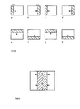
Die Erläuterung der Funktionsweise der in Figur 1 beschriebenen Anordnung erfolgt an Ein-/Ausblendbeispielen, die in Figur 2 dargestellt sind. Die Zählrichtung der Zählerstände AP und BP bzw. AZ und BZ werden mit angegeben. Die kontrollierten Inverter CIP und CIZ sind im folgenden so angesteuert, daß sie die Zählerstände der Zähler CPZ und CZZ unverändert weitergeben. In den Bildern 2, 3, 4, 5 kennzeichnet der schraffierte Teil Bildsignale aus dem Generator BG.The mode of operation of the arrangement described in FIG. 1 is explained using fade-in / fade-out examples which are shown in FIG. The counting direction of the meter readings AP and BP or AZ and BZ are also specified. The controlled inverters CIP and CIZ are controlled in the following so that they pass on the meter readings of the counters CPZ and CZZ unchanged. In Figures 2, 3, 4, 5, the hatched part identifies image signals from generator BG.
In Figur 2a wird ein Bild vom linken Rand her ausgeblendet. Bei dieser Funktion werden die Pixelzähler PZ und CPZ durch die Kontrollsignale C1 und C2 aktiviert. Ebenso der Komparator CP durch das Kontrollsignal C5. Am Pixelzähler PZ liegt noch das Zählsignal S1 mit der Abtastfrequenz, die bei der AD-Wandlung des Videosignals benutzt wird, d.h. daß dieser Zähler seinen Zählerstand entlang der horizontalen Bildlinie jeweils entsprechend der Horizontalauflösung des Bildes mit jedem Pixel erhöht. Dieser Zähler wird nach jeder Zeile rückgesetzt und beginnt mit Anfang der nächsten Zeile wieder zu zählen. Der Zählerstand des Pixelzählers CPZ wird nach jedem Bild oder Halbbild erhöht. Die Zählwerte AP und BP der Zähler werden im Komparator CP miteinander verglichen. Durch die Komparatorausgänge CP1 und CP2 wird das Kontrollmodul KM angesteuert, das wiederum den Multiplexer M ansteuert. Diese Ansteuerung erfolgt so, daß jeweils das Signal des Generators BG, z. B. ein vorgegebener Grauwert, durchgesteuert wird, wenn der Zählerstand des Pixelzählers PZ kleiner ist, als der Zählerstand des Pixelzählers CPZ, d.h. wenn die aktuelle Position des verarbeiteten Videosignals links der Grenze G1 in Figur 2a ist. Die Grenze G1 wird dabei durch den Pixelzähler CPZ vorgegeben. Entsprechend wird das Videosignal durchgesteuert, wenn die aktuelle Position des verarbeiteten Videosignals rechts von G1 liegt, d. h. wenn der Zählerstand AP größer ist als der Zählerstand BP.In Figure 2a, an image is hidden from the left edge. With this function, the pixel counters PZ and CPZ are activated by the control signals C1 and C2. Likewise the comparator CP by the control signal C5. At the pixel counter PZ is still the counting signal S1 with the sampling frequency, which is used in the AD conversion of the video signal, ie that this counter has its counter reading along the horizontal line of the image increased with each pixel according to the horizontal resolution of the image. This counter is reset after each line and starts counting again at the beginning of the next line. The count of the pixel counter CPZ is increased after each picture or field. The count values AP and BP of the counters are compared with one another in the comparator CP. The comparator outputs CP1 and CP2 control the control module KM, which in turn controls the multiplexer M. This control is carried out so that the signal of the generator BG, z. B. a predetermined gray value, is controlled when the counter reading of the pixel counter PZ is smaller than the counter reading of the pixel counter CPZ, ie when the current position of the processed video signal is to the left of the limit G1 in FIG. 2a. The limit G1 is specified by the pixel counter CPZ. The video signal is controlled accordingly if the current position of the processed video signal is to the right of G1, ie if the counter reading AP is greater than the counter reading BP.
Mit dem Kontrollsignal C71 wird noch die Logikschaltung SG aktiviert, die sicherstellt, daß der Synchronisationsrahmen des Videosignals nicht gestört wird. Je nach der geforderten zeitlichen Auflösung des Ausblendvorgangs kann die Dimensionierung der Zähler um ein oder mehrere bits reduziert werden. Wenn z. B. pro Bild oder Halbbild die Grenze G1 um 2 Pixel verschoben wird, kann das niedrigste bit des Pixelzählers PZ vernachlässigt werden und der Pixelzähler CPZ zählt pro Bild oder Halbbild nur einen Wert höher, womit ein bit beim Pixelzähler CPZ eingespart ist, ebenso wird beim Komparator ein Vergleichsbit eingespart.The control circuit C71 also activates the logic circuit SG, which ensures that the synchronization frame of the video signal is not disturbed. Depending on the required temporal resolution of the blanking process, the dimensioning of the counters can be reduced by one or more bits. If e.g. B. per frame or field, the boundary G1 is shifted by 2 pixels, the lowest bit of the pixel counter PZ are neglected and the pixel counter CPZ counts only one value higher per image or field, which saves one bit in the pixel counter CPZ, and also saves a comparison bit in the comparator.
Beim Einblenden eines Bildes wird durch die Kontrolleinheit KM der Multiplexer (M) so angesteuert, daß das Videosignal durchgesteuert wird, wenn der Pixelzähler PZ einen kleineren Wert aufweist als der Pixelzähler CPZ, d.h. wenn die aktuelle Position des verarbeiteten Videosignals links von G11 in Bild 2b liegt. Das Kontrollsignal C7 aktiviert dabei das Kontrollmodul KM und gibt ihm den Arbeitsmodus, d.h. den Ein- oder Ausblendvorgang an.When an image is faded in, the control unit KM drives the multiplexer (M) in such a way that the video signal is turned on when the pixel counter PZ has a smaller value than the pixel counter CPZ, i.e. if the current position of the processed video signal is to the left of G11 in Figure 2b. The control signal C7 activates the control module KM and gives it the working mode, i.e. the fade in or out process.
Das Ein- und Ausblenden von der rechten Seite erfolgt in der gleichen Weise wie dies beim Ein-/Ausblenden von der linken Seite aus beschrieben ist, wobei der Zähler CPZ nicht von Null nach oben zu zählen beginnt, sondern von seinem höchsten Wert, also an rechter Position, nach unten zählt. Die Bilder 2c und 2d zeigen den Verlauf des Ein- und Ausblendens von der rechten Seite.Fading in and out from the right side takes place in the same way as described for fading in / out from the left side, the counter CPZ not starting to count up from zero, but from its highest value, that is, from right position, counts down. Pictures 2c and 2d show the course of fading in and out from the right side.
Das Aus- und Einblenden von oben nach unten oder von unten nach oben, dargestellt in den Figuren 2e bis 2h, erfolgt in der gleichen Weise wie von links nach rechts und umgekehrt, wobei in diesem Fall die Zeilenzähler ZZ und CZZ, und der entsprechende Komparator CZ aktiv sind.The fading in and out from top to bottom or from bottom to top, shown in FIGS. 2e to 2h, is carried out in the same way as from left to right and vice versa, in which case the line counters ZZ and CZZ, and the corresponding comparator CZ are active.
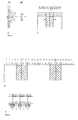
In Fig. 3 wird dargestellt, wie der Ein-/Ausblendvorgang in der Mitte startet. Der Pixelzähler CPZ wird in diesem Fall so angesteuert, daß er Von seinem oberen Grenzwert, in diesem Fall dem Zählwert in der Bildmitte entspricht, nach unten zählt. Der Pixelzähler PZ zählt von einem Anfangswert hoch, so daß er in der Bildmitte den oberen Grenzwert des Pixelzählers CPZ erreicht und danach ein Übertragsbit erzeugt und von Null zu zählen beginnt. Das Übertragsbit steuert den kontrollierten Inverter CIP, der den Zählerstand des Pixelzählers CPZ invertiert. Zugleich wird über das Kontrollsignal C5 der Komparator CP so beeinflußt, daß die Vergleichsbedingung umgekehrt wird. Diese Ansteuerung bewirkt, daß der Pixelzähler bei jeder Zeile von einem Anfangswert zur Bildmitte zählt und danach von Null bis zum Endwert, wobei der Endwert der invertierte Anfangswert ist. Der Vergleich findet bis zur Bildmitte mit dem Wert des Pixelzählers in der Form statt, daß beim Ausblenden ein Grauwert durchgesteuert wird, wenn der Zählerwert BP des Pixelzählers CPZ kleiner ist als der Zählerwert AP des Pixelzählers PZ, im anderen Fall wird das Videosignal durchgesteuert.3 shows how the fade-in / fade-out process starts in the middle. In this case, the pixel counter CPZ is controlled in such a way that it counts down from its upper limit value, in this case the count value in the center of the image. The pixel counter PZ counts up from an initial value so that it reaches the upper limit value of the pixel counter CPZ in the center of the image and then generates a carry bit and starts counting from zero. The carry bit controls the controlled inverter CIP, which inverts the count of the pixel counter CPZ. At the same time, the comparator CP is influenced by the control signal C5 so that the comparison condition is reversed. This control causes the pixel counter to count from an initial value to the center of the image on each line and then from zero to the final value, the final value being the inverted initial value. The comparison takes place up to the center of the picture with the value of the pixel counter in the form that a gray value is controlled when the value is hidden, if the counter value BP of the pixel counter CPZ is smaller than the counter value AP of the pixel counter PZ, in the other case the video signal is controlled.
Nach Überschreiten der Bildmitte wird der Zählwert des Pixelzählers PZ mit dem invertierten Wert des Pixelzählers CPZ verglichen, wobei nach der Bildmitte der Grauwert durchgesteuert wird, wenn der Wert des Pixelzählers PZ kleiner oder gleich dem invertierten Wert des Pixelzählers CPZ ist, also umgekehrt als vor der Bildmitte.After the center of the image has been exceeded, the count value of the pixel counter PZ is compared with the inverted value of the pixel counter CPZ, the gray value being controlled after the center of the image if the value of the pixel counter PZ is less than or equal to the inverted value of the pixel counter CPZ, i.e. vice versa than before Middle of picture.
In Figur 4a und 4b wird dieser Vorgang noch erläutert, unter der Annahme, daß die horizontale Auflösung 12 Pixel beträgt. Der Anfangswert liegt bei 2, binär: 010. Der Zählwert AP des Pixelzähles PZ wird von 2 beginnend bis nach 7, binär 111, hochgezählt. Anschließend entsteht ein Übertragsbit und der Zähler zählt bei 0 weiter bis 5, binär 101, invertiert 010, also 2. Das Übertragsbit steuert die Invertierung des Zählwertes BP des Pixelzählers CPZ. Ebenso muß an dieser Stelle die Komparatorbedingung vertauscht werden, damit innerhalb der Grauwertgrenzen auch tatsächlich der Grauwert durchgeschaltet wird.This process is explained in FIGS. 4a and 4b, assuming that the horizontal resolution is 12 pixels. The initial value is 2, binary: 010. The count AP of the pixel counter PZ is counted up from 2 to after 7,
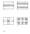
Die Figuren 5a und 5b zeigen, wie durch feinere Unterteilung (Fig. 5a) bzw. durch andere Zählergrenzwerte die Ein-/Ausblendmöglichkeiten weiter ausgebaut werden können, so daß man von beliebig vielen Stellen streifenförmig ein- oder ausblenden kann.FIGS. 5a and 5b show how the fade-in / fade-out options can be expanded further by means of finer subdivision (FIG. 5a) or by means of other counter limit values, so that strips of any number can be faded in or out.
Das streifenförmige Ein-/Ausblenden ist ebenso in der oben beschriebenen Weise in vertikaler Richtung möglich, so daß sich Muster nach Fig. 6a, 6b, ergeben.The striped fading in / out is also possible in the manner described above in the vertical direction, so that patterns according to FIGS. 6a, 6b result.
Durch gleichzeitige Anwendung von sowohl horizontaler als auch vertikaler streifenförmiger Ein-/Ausblendung entstehen schachbrettartige Muster, wie in Fig. 6c, 6d, dargestellt.The simultaneous use of both horizontal and vertical strip-shaped fade-in / fade-out results in checkerboard-like patterns, as shown in FIGS. 6c, 6d.
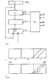
Eine weitere vorteilhafte Ausgestaltung der Erfindung ergibt sich, wenn man den Pixelzähler CPZ in der in Figur 7 dargestellten Weise ergänzt.A further advantageous embodiment of the invention results if the pixel counter CPZ is supplemented in the manner shown in FIG.
Hier wird der Zählerstand BP zusätzlich noch auf einen Multiplexereingang AM des Multiplexers MUX geführt, an dessen zweiten Eingang BM ein externer Zählwert anliegt, wobei durch das Kontrollsignal C9, welches vom Timing/Kontrollmodul TKM kommt, vorgegeben wird, welches der beiden Eingangssignale am Ausgang des Multiplexers MUX anliegt. Das Ausgangssignal AMUX führt zu einem Latch L, dessen Ausgang zum Pixelzähler CPZ führt. Die Ansteuerung des Latch L erfolgt durch das Kontrollsignal C8.Here, the counter reading BP is additionally fed to a multiplexer input AM of the multiplexer MUX, at the second input BM of which an external count is present, whereby the control signal C9, which comes from the timing / control module TKM, specifies which of the two input signals at the output of the Multiplexers MUX is present. The output signal AMUX leads to a latch L, the output of which leads to the pixel counter CPZ. Latch L is controlled by control signal C8.
Mit dieser Anordnung ist es möglich, den Ein-/Ausblendvorgang diagonal -von den Ecken beginnend- zu gestalten.With this arrangement it is possible to design the fade-in / fade-out process diagonally starting from the corners.
Figur 8 dient zur Erläuterung der Vorgehensweise. Die Pixelzähler haben jetzt einen Zählbereich, der so gestaltet ist, daß über 3 nebeneinander liegende Bildzeilen gezählt wird, zunächst über ein virtuelles, nicht sichtbares Bild (a), dann über den sichtbaren Bereich (b) und schließlich wieder über einen virtuellen Bereich (c). Der Grund für diese Zählweise ist aus Fig. 8 ersichtlich. Um im Bildbereich eine diagonale Grenze zu bilden, die in der rechten unteren Ecke beginnt, muß man, wenn die Grenze nicht durch Speicherwerte vorgegeben werden soll, was sehr aufwendig und teuer ist, die Grenze oben rechts im virtuellen Bild beginnen lassen. Zunächst bildet sich eine Diagonale 1 im virtuellen Bereich. Wenn die Diagonale beim nächsten Bild oder Halbbild nach links verschoben wird, dann macht sich die Diagonale 2 in der rechten unteren Ecke bemerkbar. Je weiter die Diagnale verschoben wird, desto mehr geht sie in den sichtbaren Bereich und es entsteht der Eindruck, daß die Diagonale von rechts unten nach links oben geschoben wurde. Mit Fig. 8b wird erläutert, wie die Diagonale erzeugt wird. In dieser Figur sind die Zählrichtungen der beiden Pixelzähler PZ und CPZ eingetragen, wobei AP der Zählwert von PZ und BP der Zählwert von CPZ ist.Figure 8 serves to explain the procedure. The pixel counters now have a counting area that is designed in such a way that counting is carried out over 3 adjacent picture lines, first over a virtual, invisible picture (a), then over the visible area (b) and finally again over a virtual area (c ). The reason for this method of counting can be seen from FIG. 8. In order to form a diagonal border in the image area, which begins in the lower right corner, if the border is not to be specified by stored values, which is very complex and expensive, the border has to begin in the top right of the virtual image. First, a diagonal 1 is formed in the virtual area. If the diagonal is shifted to the left in the next picture or field, then the diagonal 2 in the lower right corner noticeable. The further the diagnosis is moved, the more it goes into the visible area and the impression is created that the diagonal has been moved from the bottom right to the top left. 8b explains how the diagonal is generated. The counting directions of the two pixel counters PZ and CPZ are entered in this figure, AP being the count value of PZ and BP being the count value of CPZ.
Der Zähler AP zählt von einem Anfangswert zum Endwert einer Zeile und beginnt bei der nächsten Zeile wieder mit dem Anfangswert usw. Der Pixelzähler CPZ beginnt mit dem Endwert zu zählen. Der Komparator CP vergleicht beide Zählwerte und steuert das Kontrollmodul KM so an, daß es jeweils abhängig vom Vergleichsergebnis an den Multiplexer M ein Signal gibt, so daß entweder das Videosignal oder z.B. ein Grauwert aus dem Generator BG durchgeschaltet wird. Bei Ausblendung von rechts unten nach links oben wird jeweils das Videosignal durchgesteuert, wenn der Zählwert AP kleiner ist als BP oder im nicht sichtbaren Bereich liegt und z.B. der Grauwert wird durchgesteuert, wenn im sichtbaren Bereich der Zählwert AP größer ist als der Zählwert BP.The counter AP counts from an initial value to the end value of a line and starts again with the start value on the next line, etc. The pixel counter CPZ begins to count with the end value. The comparator CP compares both counts and controls the control module KM so that there is a signal to the multiplexer M depending on the comparison result, so that either the video signal or e.g. a gray value from the generator BG is switched through. When fading out from the bottom right to the top left, the video signal is controlled when the count AP is less than BP or in the invisible range and e.g. The gray value is controlled when the count value AP is greater than the count value BP in the visible range.
Der Pixelzähler wird so angesteuert, daß er vom oberen Grenzwert nach unten zählt, wobei der Zählwert nach Fig. 8b nach jeder Zeile um einen Zählwert erniedrigt wird. Der Wert nach dem ersten Dekrement, hier also der Wert in der zweiten Zeile, wird über einen Multiplexer MUX an ein Latch geführt und dort gespeichert. Dieser Wert wird beim nächsten Bild in der ersten Zeile als Anfangswert für das Bild in den Pixelzähler CPZ geladen. Damit wird die Diagonale um ein Pixel nach links geschoben. Die Ansteuerung für den Multiplexer, an dessen zweiten Eingang ein externer Anfangswert für die erste Zeile des ersten Bildes eingegeben wird, und die Ansteuerung für das Latch erfolgen nach obigen Gesichtspunkten vom Timing/Kontrollmodul TKM aus.The pixel counter is controlled in such a way that it counts down from the upper limit value, the count value according to FIG. 8b being decreased by one count value after each line. The value after the first decrement, here the value in the second line, is passed to a latch via a MUX and stored there. This value is used as the initial value for the next picture in the first line Image loaded into the pixel counter CPZ. This shifts the diagonal to the left by one pixel. The control for the multiplexer, at the second input of which an external initial value for the first line of the first image is entered, and the control for the latch are carried out from the timing / control module TKM according to the above aspects.
Die Steigung kann beliebig verändert werden, in dem man nicht nach jeder Zeile ein Pixel erhöht, sondern nach einer beliebig vorgebbaren Zeilenzahl um eine vorgebbare Pixelzahl erhöht.The slope can be changed as desired by not increasing a pixel after each line, but increasing it by a predeterminable number of pixels after an arbitrary number of lines.
Ein- und Ausblendvorgänge sind unter entsprechender Ansteuerung der Zähler, des Latch usw. nach dem oben beschriebenen Prinzip aus allen vier Ecken möglich.Fade-in and fade-out processes are possible from all four corners if the counters, latches, etc. are activated accordingly.
Statt des im Generator BG beispielsweise erzeugten Grauwertes kann auch ein zweites Videosignal an den Multiplexer M angelegt werden, wodurch die beschriebenen Ein-/Ausblendeigenschaften auch zum Überblenden von einem Bild auf ein anderes Bild genutzt werden können.Instead of the gray value generated in the generator BG, for example, a second video signal can also be applied to the multiplexer M, as a result of which the described fade-in / fade-out properties can also be used for cross-fading from one image to another image.
Claims (6)
- die Anordnung einen Pixelzähler (PZ), der die Horizontalposition des momentan verarbeiteten Videosignals angibt, und einen Pixelzähler (CPZ) enthält, der eine vorgebbare Horizontalposition eines Videosignals angibt, und die Zählerstände der Pixelzähler in einem Komparator (CP) verglichen werden,
- die Anordnung einen Zeilenzähler (ZZ), der die aktuelle Vertikalposition des Videosignals angibt, und einen Zeilenzähler (CZZ) enthält, der eine vorgebbare Vertikalposition eines Videosignals angibt, und die Zählerstände der Zeilenzähler in einem Komparator (CZ) verglichen werden,
- die Anordnung ein Kontrollmodul (KM) enthält, das in Abhängigkeit von den Ausgangssignalen der Komparatoren (CP) und (CZ) einen Multiplexer (M) ansteuert, an dessen Eingängen ein Videosignal (VI) und ein in einem Generator BG erzeugtes zweites Videosignal anliegen,
- die Steuersignale für die Elemente der Anordnung im Kontrollmodul (KM) erzeugt werden, und
- die Anordnung über kontrollierte Inverter (CIP) und (CIZ) verfügt, welche mit den Ausgängen des Pixelzählers (CPZ) bzw. des Zeilenzählers (CZZ) verbunden sind.1. Arrangement for generating fade-in and fade-out effects in video devices whose image signals are digitally processed, characterized in that
the arrangement contains a pixel counter (PZ), which indicates the horizontal position of the currently processed video signal, and a pixel counter (CPZ), which indicates a predeterminable horizontal position of a video signal, and the counter readings of the pixel counters are compared in a comparator (CP),
the arrangement includes a line counter (ZZ), which indicates the current vertical position of the video signal, and a line counter (CZZ), which indicates a predeterminable vertical position of a video signal, and the counter readings of the line counters are compared in a comparator (CZ),
- The arrangement contains a control module (KM) which controls a multiplexer (M) depending on the output signals of the comparators (CP) and (CZ), at whose inputs a video signal (VI) and a second video signal generated in a generator BG are present ,
- The control signals for the elements of the arrangement in the control module (KM) are generated, and
- The arrangement has controlled inverters (CIP) and (CIZ), which are connected to the outputs of the pixel counter (CPZ) and the line counter (CZZ).
- das Zählerausgangssignal des Zählers (CPZ, CZZ) an einen Multiplexer (MUX) geführt wird,
- dem zweiten Eingang des Multiplexers (MUX) ein externes Zählersignal zugeführt wird,
- die Ansteuerung des Multiplexers (MUX) vom Timing/ Kontrollmodul (TKM) über eine Leitung (C9) des Timing und Konrollbusses (TKB) erfolgt,
- der Ausgang des Multiplexers (MUX) an den Eingang eines Zwischenspeichers (L) führt, welches vom Timing/ Kontrollmodul (TKM) über die Verbindung (C 8) angesteuert wird, und
- der Ausgang des Zwischenspeichers (L) zur kontrollierten Datenübergabe mit dem Eingang des Zählers (CPZ, CZZ) verbunden ist.6. Arrangement according to one or more of claims 1 to 5, characterized in that
the counter output signal of the counter (CPZ, CZZ) is passed to a multiplexer (MUX),
an external counter signal is fed to the second input of the multiplexer (MUX),
- The multiplexer (MUX) is controlled by the timing / control module (TKM) via a line (C9) of the timing and control bus (TKB),
- The output of the multiplexer (MUX) leads to the input of a buffer (L) which is controlled by the timing / control module (TKM) via the connection (C 8), and
- The output of the buffer (L) for controlled data transfer is connected to the input of the counter (CPZ, CZZ).
Applications Claiming Priority (2)
| Application Number | Priority Date | Filing Date | Title |
|---|---|---|---|
| DE3920617A DE3920617A1 (en) | 1989-06-23 | 1989-06-23 | ARRANGEMENT FOR GENERATING FADE IN AND FADE OUT EFFECTS |
| DE3920617 | 1989-06-23 |
Publications (3)
| Publication Number | Publication Date |
|---|---|
| EP0403752A2 true EP0403752A2 (en) | 1990-12-27 |
| EP0403752A3 EP0403752A3 (en) | 1992-09-23 |
| EP0403752B1 EP0403752B1 (en) | 1995-12-27 |
Family
ID=6383433
Family Applications (1)
| Application Number | Title | Priority Date | Filing Date |
|---|---|---|---|
| EP90107145A Expired - Lifetime EP0403752B1 (en) | 1989-06-23 | 1990-04-14 | Device generating fade-in, fade-out effects |
Country Status (4)
| Country | Link |
|---|---|
| EP (1) | EP0403752B1 (en) |
| JP (1) | JPH0335670A (en) |
| AT (1) | ATE132311T1 (en) |
| DE (2) | DE3920617A1 (en) |
Cited By (2)
| Publication number | Priority date | Publication date | Assignee | Title |
|---|---|---|---|---|
| EP0508785A2 (en) * | 1991-04-11 | 1992-10-14 | Canon Kabushiki Kaisha | Scrolling superimposition of generated title |
| WO1997017802A1 (en) * | 1995-11-09 | 1997-05-15 | Siemens Aktiengesellschaft | Circuit arrangement for fading between picture sequences |
Citations (3)
| Publication number | Priority date | Publication date | Assignee | Title |
|---|---|---|---|---|
| US3944731A (en) * | 1975-03-03 | 1976-03-16 | Sarkes Tarzian, Inc. | Video special effects generator |
| US4356511A (en) * | 1978-05-23 | 1982-10-26 | Sony Corporation | Digital soft-edge video special effects generator |
| US4488180A (en) * | 1982-04-02 | 1984-12-11 | Chyron Corporation | Video switching |
-
1989
- 1989-06-23 DE DE3920617A patent/DE3920617A1/en not_active Withdrawn
-
1990
- 1990-04-14 AT AT90107145T patent/ATE132311T1/en not_active IP Right Cessation
- 1990-04-14 DE DE59009998T patent/DE59009998D1/en not_active Expired - Lifetime
- 1990-04-14 EP EP90107145A patent/EP0403752B1/en not_active Expired - Lifetime
- 1990-06-20 JP JP2160059A patent/JPH0335670A/en active Pending
Patent Citations (3)
| Publication number | Priority date | Publication date | Assignee | Title |
|---|---|---|---|---|
| US3944731A (en) * | 1975-03-03 | 1976-03-16 | Sarkes Tarzian, Inc. | Video special effects generator |
| US4356511A (en) * | 1978-05-23 | 1982-10-26 | Sony Corporation | Digital soft-edge video special effects generator |
| US4488180A (en) * | 1982-04-02 | 1984-12-11 | Chyron Corporation | Video switching |
Cited By (3)
| Publication number | Priority date | Publication date | Assignee | Title |
|---|---|---|---|---|
| EP0508785A2 (en) * | 1991-04-11 | 1992-10-14 | Canon Kabushiki Kaisha | Scrolling superimposition of generated title |
| EP0508785A3 (en) * | 1991-04-11 | 1993-03-03 | Canon Kabushiki Kaisha | Scrolling superimposition of generated title |
| WO1997017802A1 (en) * | 1995-11-09 | 1997-05-15 | Siemens Aktiengesellschaft | Circuit arrangement for fading between picture sequences |
Also Published As
| Publication number | Publication date |
|---|---|
| EP0403752A3 (en) | 1992-09-23 |
| DE3920617A1 (en) | 1991-01-03 |
| ATE132311T1 (en) | 1996-01-15 |
| JPH0335670A (en) | 1991-02-15 |
| EP0403752B1 (en) | 1995-12-27 |
| DE59009998D1 (en) | 1996-02-08 |
Similar Documents
| Publication | Publication Date | Title |
|---|---|---|
| DE3609887C2 (en) | Circuit arrangement for generating design factors for a recursive filter for video signals | |
| DE69938227T2 (en) | Method and apparatus for motion artifact and noise reduction in video image processing | |
| DE4423214C2 (en) | Multinorm decoder for video signals and method for decoding video signals | |
| DE3138604C2 (en) | ||
| DE4121727C2 (en) | Motion signal processor | |
| EP0224302B1 (en) | Circuitry for increasing the sharpness of colour edges | |
| DE4129656C2 (en) | Video signal display device on a monitor | |
| DE2830420A1 (en) | CIRCUIT ARRANGEMENT FOR TELEVISION INTRODUCTION | |
| DE3044761A1 (en) | DIGITAL MAGNIFICATION SYSTEM FOR A SCANNED IMAGE | |
| EP0425041B1 (en) | Digital circuit for the processing of an analogue picture signal with an asynchronous clock | |
| DE69935753T2 (en) | A clock generating circuit for a display device capable of displaying an image regardless of the score in a horizontal period of an input signal | |
| DE3234178C2 (en) | ||
| DE4327779C1 (en) | Method and circuit arrangement for a television set for the purpose of reducing flicker | |
| EP0403752B1 (en) | Device generating fade-in, fade-out effects | |
| EP0167673A1 (en) | X-ray diagnostic apparatus | |
| DE3505358C2 (en) | ||
| EP0403759B1 (en) | Arrangement for obtaining pictoral effects in video apparatus | |
| DE4009456C2 (en) | Image display device | |
| DE3332284A1 (en) | DIAGNOSTIC X-RAY DEVICE | |
| EP0179526A2 (en) | Sampling control circuit | |
| DE19748721C2 (en) | Graduated reset of the filter coefficient in an arrangement for noise suppression in video images | |
| EP0639922A2 (en) | Motion detection circuit for picture signal | |
| DE19532151A1 (en) | Motion detector and one-touch interpolator using it | |
| EP0415086B1 (en) | Chrominance displacement generation device | |
| DE3150008A1 (en) | System for reducing noise in a television signal |
Legal Events
| Date | Code | Title | Description |
|---|---|---|---|
| PUAI | Public reference made under article 153(3) epc to a published international application that has entered the european phase |
Free format text: ORIGINAL CODE: 0009012 |
|
| AK | Designated contracting states |
Kind code of ref document: A2 Designated state(s): AT DE FR GB IT |
|
| PUAL | Search report despatched |
Free format text: ORIGINAL CODE: 0009013 |
|
| AK | Designated contracting states |
Kind code of ref document: A3 Designated state(s): AT DE FR GB IT |
|
| 17P | Request for examination filed |
Effective date: 19921022 |
|
| 17Q | First examination report despatched |
Effective date: 19940818 |
|
| RAP1 | Party data changed (applicant data changed or rights of an application transferred) |
Owner name: GRUNDIG E.M.V. ELEKTRO-MECHANISCHE VERSUCHSANSTALT |
|
| GRAA | (expected) grant |
Free format text: ORIGINAL CODE: 0009210 |
|
| AK | Designated contracting states |
Kind code of ref document: B1 Designated state(s): AT DE FR GB IT |
|
| PG25 | Lapsed in a contracting state [announced via postgrant information from national office to epo] |
Ref country code: IT Free format text: LAPSE BECAUSE OF FAILURE TO SUBMIT A TRANSLATION OF THE DESCRIPTION OR TO PAY THE FEE WITHIN THE PRESCRIBED TIME-LIMIT;WARNING: LAPSES OF ITALIAN PATENTS WITH EFFECTIVE DATE BEFORE 2007 MAY HAVE OCCURRED AT ANY TIME BEFORE 2007. THE CORRECT EFFECTIVE DATE MAY BE DIFFERENT FROM THE ONE RECORDED. Effective date: 19951227 |
|
| REF | Corresponds to: |
Ref document number: 132311 Country of ref document: AT Date of ref document: 19960115 Kind code of ref document: T |
|
| GBT | Gb: translation of ep patent filed (gb section 77(6)(a)/1977) |
Effective date: 19960105 |
|
| REF | Corresponds to: |
Ref document number: 59009998 Country of ref document: DE Date of ref document: 19960208 |
|
| ET | Fr: translation filed | ||
| PLBE | No opposition filed within time limit |
Free format text: ORIGINAL CODE: 0009261 |
|
| STAA | Information on the status of an ep patent application or granted ep patent |
Free format text: STATUS: NO OPPOSITION FILED WITHIN TIME LIMIT |
|
| 26N | No opposition filed | ||
| REG | Reference to a national code |
Ref country code: FR Ref legal event code: TP |
|
| REG | Reference to a national code |
Ref country code: GB Ref legal event code: 746 Effective date: 20010322 |
|
| REG | Reference to a national code |
Ref country code: FR Ref legal event code: D6 |
|
| REG | Reference to a national code |
Ref country code: GB Ref legal event code: IF02 |
|
| REG | Reference to a national code |
Ref country code: GB Ref legal event code: 732E |
|
| REG | Reference to a national code |
Ref country code: FR Ref legal event code: TP |
|
| PGFP | Annual fee paid to national office [announced via postgrant information from national office to epo] |
Ref country code: DE Payment date: 20090423 Year of fee payment: 20 Ref country code: AT Payment date: 20090423 Year of fee payment: 20 Ref country code: FR Payment date: 20090421 Year of fee payment: 20 |
|
| PGFP | Annual fee paid to national office [announced via postgrant information from national office to epo] |
Ref country code: GB Payment date: 20090424 Year of fee payment: 20 |
|
| REG | Reference to a national code |
Ref country code: GB Ref legal event code: PE20 Expiry date: 20100413 |
|
| PG25 | Lapsed in a contracting state [announced via postgrant information from national office to epo] |
Ref country code: GB Free format text: LAPSE BECAUSE OF EXPIRATION OF PROTECTION Effective date: 20100413 |
|
| PG25 | Lapsed in a contracting state [announced via postgrant information from national office to epo] |
Ref country code: DE Free format text: LAPSE BECAUSE OF EXPIRATION OF PROTECTION Effective date: 20100414 |