EP0403254A2 - Hermetic pressure sensor - Google Patents
Hermetic pressure sensor Download PDFInfo
- Publication number
- EP0403254A2 EP0403254A2 EP90306444A EP90306444A EP0403254A2 EP 0403254 A2 EP0403254 A2 EP 0403254A2 EP 90306444 A EP90306444 A EP 90306444A EP 90306444 A EP90306444 A EP 90306444A EP 0403254 A2 EP0403254 A2 EP 0403254A2
- Authority
- EP
- European Patent Office
- Prior art keywords
- diaphragm
- membrane
- pressure
- sensing element
- central
- Prior art date
- Legal status (The legal status is an assumption and is not a legal conclusion. Google has not performed a legal analysis and makes no representation as to the accuracy of the status listed.)
- Granted
Links
Images
Classifications
-
- H—ELECTRICITY
- H01—ELECTRIC ELEMENTS
- H01H—ELECTRIC SWITCHES; RELAYS; SELECTORS; EMERGENCY PROTECTIVE DEVICES
- H01H35/00—Switches operated by change of a physical condition
- H01H35/24—Switches operated by change of fluid pressure, by fluid pressure waves, or by change of fluid flow
- H01H35/34—Switches operated by change of fluid pressure, by fluid pressure waves, or by change of fluid flow actuated by diaphragm
- H01H35/343—Switches operated by change of fluid pressure, by fluid pressure waves, or by change of fluid flow actuated by diaphragm by snap acting diaphragm
-
- G—PHYSICS
- G01—MEASURING; TESTING
- G01L—MEASURING FORCE, STRESS, TORQUE, WORK, MECHANICAL POWER, MECHANICAL EFFICIENCY, OR FLUID PRESSURE
- G01L9/00—Measuring steady of quasi-steady pressure of fluid or fluent solid material by electric or magnetic pressure-sensitive elements; Transmitting or indicating the displacement of mechanical pressure-sensitive elements, used to measure the steady or quasi-steady pressure of a fluid or fluent solid material, by electric or magnetic means
- G01L9/0041—Transmitting or indicating the displacement of flexible diaphragms
- G01L9/0042—Constructional details associated with semiconductive diaphragm sensors, e.g. etching, or constructional details of non-semiconductive diaphragms
- G01L9/0048—Details about the mounting of the diaphragm to its support or about the diaphragm edges, e.g. notches, round shapes for stress relief
-
- G—PHYSICS
- G01—MEASURING; TESTING
- G01L—MEASURING FORCE, STRESS, TORQUE, WORK, MECHANICAL POWER, MECHANICAL EFFICIENCY, OR FLUID PRESSURE
- G01L9/00—Measuring steady of quasi-steady pressure of fluid or fluent solid material by electric or magnetic pressure-sensitive elements; Transmitting or indicating the displacement of mechanical pressure-sensitive elements, used to measure the steady or quasi-steady pressure of a fluid or fluent solid material, by electric or magnetic means
- G01L9/0041—Transmitting or indicating the displacement of flexible diaphragms
- G01L9/0072—Transmitting or indicating the displacement of flexible diaphragms using variations in capacitance
- G01L9/0075—Transmitting or indicating the displacement of flexible diaphragms using variations in capacitance using a ceramic diaphragm, e.g. alumina, fused quartz, glass
Landscapes
- Physics & Mathematics (AREA)
- General Physics & Mathematics (AREA)
- Chemical & Material Sciences (AREA)
- Fluid Mechanics (AREA)
- Engineering & Computer Science (AREA)
- Ceramic Engineering (AREA)
- Analytical Chemistry (AREA)
- Measuring Fluid Pressure (AREA)
Abstract
Description
- This invention relates to an hermetic pressure sensor and, more specifically, to an hermetic pressure sensor for gauge and absolute pressure sensing elements for use in environments requiring hermeticity, such as refrigeration systems, chemically hostile, expensive or poisonous pressure medias, fluids or other such environments.
- Sensing of pressures in environments requiring hermeticity, such as refrigeration systems, chemically hostile, expensive or poisonous pressure medias, fluids or other such environments generally requires the use of pressure sensors having walls which are impermeable to such environments and which are chemically stable, corrosion resistant and insensitive to temperature fluctuations. Such pressure sensors must hermetically seal or isolate the pressure sensing element from the pressure providing medium and prevent leakage or seepage of the pressure providing medium into the environment.
- One type of sensor utilized for such pressure sensing is based upon the mechanical principle of the elastic property of materials (spring rate) wherein at least one wall of the sensor is designed and manufactured to produce predictable elastic deformation or deflection under pressure. This deflection is used to either produce electrical analog signals in the case of transducers or to mechanically open and close a set of contacts in the case of pressure switches. To accurately assess the pressures being measured, this elastic wall must be in direct contact with the pressure providing medium and must be joined to other walls of the pressure providing medium containment device in a manner which prevents or minimizes mechanical coupling of stray forces and stray deflections from such other walls into the elastic wall used for pressure measurement.
- Conventionally, the elastic wall in such pressure sensors is formed utilizing a diaphragm which provides a type of hermeticity and is produced by using flexible man-made materials, such as rubber sheet, Kapton, silicone rubber, silicone gels and the like. The application of such prior art pressure sensors often requires that hermeticity of the pressure applying system be maintained for extended periods. Low cost sensors, in general, do not meet this requirement because the pressure seals are made from organic compounds as noted above. These compounds may degrade over a long time period, and/or may degrade from repeated movement thereof and/or may not be suitable for use in conjunction with certain chemical pressure fluids and/or may not be useful over the desired or required range of temperatures.
- Other approaches, such as provided in the Klixon 20PS pressure switch sold by Texas Instruments Incorporated, obtain their hermeticity through welding or brazing of single or multiple flexible membranes (pressure discs) to a flanged, rigid pressure fitting at the outer perimeter of the disc. Undesired interaction between the welding process (weld solidification stress) material composition and the precalibrated membrane results in low precision sensors which exhibit sensitivity to temperature and early fatigue of the weld joint.
- Bellow type sensors use corrugated (highly flexible) tubes or membranes which are pre-loaded or supported by force-carrying members to limit deflection. The bellow is brazed or welded to a flanged pressure port. Corrugation provides lowest resistance to deflection and a relatively linear (not snap acting) deflection to force ratio (spring rate) which is designed to compromise between measuring accuracy and maximum permissible pressure at the pressure port. For high system pressures, the membranes must be of such thickness as not to cause permanent deformation of the bellow membrane. The bellow primarily fulfills the function of sealing the fluid medium and also has to withstand and carry a high portion of the forces exerted by the fluid pressure.
- It is therefore apparent that a hermetic sealing member is required which can be used in environments of the type described hereinabove, which provide the required properties noted hereinabove and which can also be produced relatively economically.
- The low cost hermetic seal in accordance with the present invention utilizes high temperature and chemically stable materials, including, but not limited to inconel, copper alloys, aluminum and preferably stainless steel and is joined to the pressure containment element by means of metal to metal welds, such as, but not limited to, gas tungsten arc welding (TIG) and resistance, E-beam or laser welding. The joint so produced is designed to provide hermetic sealing as well as have a high load carrying capability. Since the metal joints are purposely formed of materials having similar coefficients of thermal expansion, the risks of leakage due to thermal gradients are minimal. Also, since the joint does not participate in reaction forces generated by the pressure medium, such joint need be only the width of the membrane thickness due to the support thereof by the disc support.
- For convenience of welding, a hermetic sealing material is chosen which can be readily joined using currently available technologies. Since it is known that flexual resistance of the membrane material impacts measuring accuracy of the sensor, physical parameters are selected to obtain the lowest flexual resistance (spring rate). Spring rate is a direct function of length (diameter) and a function of material thickness according to a higher power. The hermetic sealing material thickness is selected to be as low as possible subject to conformance to the required availability and convenience of processing of the material utilized. A material thickness of 2 mils for stainless steel is preferred and imposes a measuring offset of less than -1.5 psi. However other materials can be used which can provide hermetic seals and are brazable or weldable and are about 40 per cent ductile, though the ductility is not critical. Examples of other materials that can be used are plain steel and copper alloys. To provide intimate contact with pressure sensing elements, the material should have large elongation value or ductility and low proportional limit. Annealed stainless steel provides these desired properties and is a preferred hermetic sealing material in accordance with the present invention. The low proportional limit allows flowing of the membrane at relatively low system pressure (about 150 to 200 psi) without membrane fracturing and guarantees that the membrane contacts the force supporting structure and the sensor element. In addition, radial forces generated during membrane movement (deflection) for measuring purposes and radial forces generated by the force supporting walls (temperature and pressure) will be minimal because they will cause permanent deformation (elongation) of the membrane.
- To further minimize radial force changes, it is of importance that the diaphragm seal flange portion be located in a plane offset from the measuring surface of the diaphragm. This translates spray forces into torques which are absorbed in an area which is not used for measurement (stationary) between the flange portion and the measuring surface of the diaphragm. This area is one of single convolution, being a linear distance and a radius, is away from the hermetic joint, minimizes fracture of the joint and fracture of the membrane and minimizes transmission of stray forces into the sensing element.
- Producing and processing membranes of metal which are thinner than paper and forming convolutions, though initially appearing to be costly, requires substantially no skill in accordance with the procedures of the present invention. The hermetic seal is formed first using relatively flat metallic, preferably annealed stainless steel membranes. The forming or seating of the membrane is accomplished after all other parts of the structure are joined and the outer flange portion of the membrane has been welded thereto. The membrane will be highly wrinkled in the central measuring surface portion thereof at this point and not suitable for accurate measurement of movement in response to pressure thereon. It is therefore necessary to provide a flattened or curved central section or measuring surface of the diaphragm which is unwrinkled and offset from the plane of the flange portion of the diaphragm. This is accomplished by displacing the seated membrane under sufficiently high pressure against a flat or concave surface, depending upon the desired final shape of the diaphragm measuring surface, this surface being offset from the plane of the seat or flange portion of the membrane to reform the membrane against said surface to the shape of said surface and remove the wrinkles therefrom. The central portion of the diaphragm which abuts the flat surface will take the shape of the surface, but be offset from the plane of the diaphragm seat or flange by a distance equal to the offset of the surface therefrom.
- Measurement takes place in standard manner by placing a diaphragm movement responsive device, such as a transducer or a switch, on the surface of the pressure sensing central portion of the diaphragm and remote from the pressure receiving surface of the diaphragm.
- As an alternative embodiment, an initial pressure bias can be placed against the diaphragm from the pressure receiving side thereof to permit measurement of pressures less than ambient, such as a partial vacuum. In this way, a positive pressure against the diaphragm can be sensed even when the pressure applied is a partial vacuum.
-
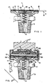
- FIGURE 1 shows a pressure sensing element having an hermetic seal in accordance with the present invention including a spring with force disc for vacuum sensors or sensors which have other than atmospheric reference pressures;
- FIGURE 2 shows a typical transducer arrangement in conjunction with the pressure sensing element of FIGURE 1; and
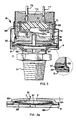
- FIGURES 3 and 3a show a typical free disc pressure switch using a bimetal or monometal calibration spring disc having a disc support in conjunction with the pressure sensing element of FIGURE 1.
- Referring first to FIGURE 1, there is shown a pressure sensing element in accordance with the present invention. The element 1 includes a
pressure fitting 3 which is shown as a tapered threaded member, it being understood that other known threaded or unthreaded such arrangements can be substituted therefor. Apressure port 5 extends through the central portion of the pressure fitting 3. The rear portion of thepressure fitting 3 includes a polygonalshaped nut portion 7 for receiving a wrench or the like for securing the pressure fitting in an appropriate receptacle therefor. Aflange 9, preferably of stainless steel, is provided as a portion of the pressure fitting 3 or, alternatively, as a separate member secured to the pressure fitting such as by brazing, resistance welding or the like. - A
membrane 11, preferably of stainless steel, is seated between theflange 9 and adisc support 13. An hermetic seal is formed among theflange 9,membrane 11 anddisc support 13 by aweldment 15 which can be provided in any well known manner, such as, for example, TIG or resistance, E-beam or laser welding. It will be noted that themembrane 11, which is preferably 2 mils in thickness, has aflat flange portion 17 positioned betweenflange 9 anddisc support 13, flatpressure sensing portion 19 offset from the plane of the flange portion and aconvolution portion 21 in form of an arc bridging the flange portion and the flat pressure sensing portion. The manner of forming themembrane 11 to the desired shape is discussed hereinabove. - As a second embodiment, referring again to FIGURE 1, there is further shown a
force disc 23 and abias spring 25, neither of which form a part of the first embodiment discussed hereinabove. As can be seen, thebias spring 25 is seated in a chamber in thefitting 3 and, at one end thereof, surrounds thepressure port 5 and at its other end is seated in a recess in theforce disc 23. Theforce disc 23 is biased against thediaphragm 11 under the bias force of thespring 25 to provide an initial normal pressure against the diaphragm ormembrane 11. In this manner, the pressure sensing element 1 can measure partial vacuums applied atpressure port 5 since a reduced but positive pressure will still be applied to themembrane 11 under such partial vacuum conditions. - Referring now to FIGURE 2, there is shown a typical transducer arrangement in conjunction with the pressure sensing element of FIGURE 1. All elements in FIGURE 2 with the same character references as in FIGURE 1 represent the same or similar structure. As can be seen, a
steel shell 31 having areference pressure port 33 is secured over theflange 9 with agasket 35 therebetween. Secured over and spaced from thedisc support 13 by agasket 39 is a ceramic capacitorpressure sensing element 37 of well known type which requires no further explanation herein. An standard electronic circuit 41 for measuring the pressure sensed as a result of the capacitance of thecapacitor 37 is positioned over the capacitor and is secured thereat by epoxy 43 which provides an environmental seal of the electronics and structural strength. Theshell 31 is secured over a flange in athermoplastic housing 45 secured in theepoxy 43.Electrical connections 47 which extend from the electronic circuit 41, through the epoxy 43 and the housing provide terminals for connection to external devices. - Referring now to FIGURES 3 and 3a, there is shown a
typical switch arrangement 51 in conjunction with the pressure sensing element of FIGURE 1. All elements in FIGURES 3 and 3a with the same character references as in FIGURE 1 represent the same or similar structure. In this embodiment, the pressure sensing structure of FIGURES 1 and 2 is replaced by a membrane ordiaphragm 55 weld to flange 9 anddisc support 53. Thediaphragm 55 is in the shape of a sector of a sphere and is supported in its central region by mono orbimetal disc 57. Thedisc 57 is initially in the shape of a sector of a sphere and causes the diaphragm to assume that same shape in its central region thereon in the same manner as the embodiments of FIGURES 1 and 2 assume a flat, unwrinkled shape as will be discussed hereinbelow. Thediaphragm 11 includes, on the low pressure side thereof, a mono orbi-metallic disc 51 secured between the diaphragm and thedisc support 13. Thedisc support 53 has anaperture portion 61 which guides apin 59 which is seated on thedisc 57 and extends through the aperture in thedisc support 13 and guide 63 to contact a normallyopen switch arm 65 which is a portion of aswitch assembly 57. Thepin 59 provides a dimensional reference point for the location ofelectrical switch arm 65. -
Switch arm 65 is secured to afirst terminal 69 which is also a part of aswitch assembly 67. A second terminal 71 which is normally spaced from theswitch arm 65 also forms a part of theswitch assembly 67. Anepoxy cast seal 73 encases theswitch assembly 67 withelectrical terminals stainless steel retainer 79 is positioned over the epoxy cast and is secured to theswitch assembly 55 by a roll-in or crimp 81 thereagainst. Ashield 83 which is formed of metal or elastomer to retain the epoxy cast 73 and shield the device from the environment is positioned over the entire structure and is retained to the switch assembly by press fitting. - The switch operates in standard manner wherein, upon the application of some predetermined minimum pressure to the
diaphragm 55, thedisc 57 will snap into its alternate position as shown by dotted lines in FIGURE 3a and force thepin 59 upward through theaperture 61. This will cause theswitch arm 65 to move against the terminal 71 to complete the circuit and provide an indication that the predetermined pressure has been sensed. - It should be noted that the distance between the plane of the diaphragm seat and a plane parallel thereto passing through the center of the diaphragm is adjustable. To produce a precise release pressure set point, the center of the
support 53 for the diaphragm is adjusted after the assembly is completed. This is performed with fluid pressures which are at least three times higher than the maximum system pressure specified for the application (500 to 3500 psi). - In order to cause the diaphragm to be wrinkle free and assume the shape of the support, the
diaphragm 55 is initially welded to theflange 9 anddisc support 53 as shown, for example, in FIGURE 3a. Thedisc 57 is then placed thereover but not necessarily in contact therewith and held in position by thedisc support 53. It should be understood that, though thedisc 57 is shown as a sector of a shperical surface, the disc can take any shape, such as, for example, flat as in FIGURES 1 and 2, and thediaphragm 55 will conform thereto as will be described. - With the
diaphragm 55 secured and the disc in place as described above, a very high pressure on the order of 500 to 3500 psi is provided at thepressure port 5. This high pressure, which is generally higher than the pressures which would normally be encountered by the device, will impinge against thediaphragm 55 and force the diaphragm against thedisc 57, causing the portion of the diaphragm contacting the disc to conform to the shape of the disc. This procedure is performed only once, prior to use of the device in practice. It can be seen that the shape of the portion of thediaphragm 55 which contacted thedisc 57 will be, after the above described application of high pressure, that of a sector of a sphere in the embodiment of FIGURES 3 and 3a and a flat member in the embodiments of FIGURES 1 and 2. The diaphragm will then retain this new shape. It can also be seen that, after application of the high pressure, the diaphragm includes a flat planar outer flange portion welded to theflange 9 anddisc support 53, aradial portion 85 of FIGURE 3a and 21 of FIGURE 1 and an interior portion which conforms to the shape of thedisc 57. The edges of the interior portion of the diaphragm which joint theradial portion 85 will be offset from the plane of the flange portion of the diaphragm where it joins theradial portion 85 whereby movements of the diaphragm due to changes of pressure thereagainst will cause flexure only along theradial portion 85. - Though the invention has been described with respect to a specific preferred embodiment thereof, many variations and modifications will immediately become apparent to those skilled in the art. It is therefore the intention that the appended claims be interpreted as broadly as possible in view of the prior art to include all such variations and modifications.
Claims (10)
and
Applications Claiming Priority (2)
| Application Number | Priority Date | Filing Date | Title |
|---|---|---|---|
| US07/366,793 US5025667A (en) | 1989-06-15 | 1989-06-15 | Hermetic pressure sensor |
| US366793 | 1994-12-30 |
Publications (3)
| Publication Number | Publication Date |
|---|---|
| EP0403254A2 true EP0403254A2 (en) | 1990-12-19 |
| EP0403254A3 EP0403254A3 (en) | 1992-08-12 |
| EP0403254B1 EP0403254B1 (en) | 1995-01-04 |
Family
ID=23444532
Family Applications (1)
| Application Number | Title | Priority Date | Filing Date |
|---|---|---|---|
| EP90306444A Expired - Lifetime EP0403254B1 (en) | 1989-06-15 | 1990-06-13 | Hermetic pressure sensor |
Country Status (4)
| Country | Link |
|---|---|
| US (1) | US5025667A (en) |
| EP (1) | EP0403254B1 (en) |
| JP (1) | JP2858882B2 (en) |
| DE (1) | DE69015704T2 (en) |
Cited By (6)
| Publication number | Priority date | Publication date | Assignee | Title |
|---|---|---|---|---|
| EP0517674A1 (en) * | 1991-06-04 | 1992-12-09 | BITRON S.p.A. | A fluid-tight electrical pressure switch for hydraulic or pneumatic circuits |
| EP0622620A1 (en) * | 1993-04-28 | 1994-11-02 | BITRON "B" S.p.A. | Pressure sensor for controlling air conditioning systems and the like |
| EP0764960A2 (en) * | 1995-09-19 | 1997-03-26 | Texas Instruments Incorporated | Fluid pressure responsive electric switch and method for assembling same |
| EP0781402A1 (en) * | 1994-09-12 | 1997-07-02 | Ivac Holdings, Inc. | Dome-shaped pressure vessel and method for optimizing same |
| GB2330205A (en) * | 1997-10-13 | 1999-04-14 | Motorola Inc | Method and apparatus for testing a nozzle of a pick-and-place system |
| EP1211496A2 (en) * | 2000-11-30 | 2002-06-05 | Nagano Keiki Co., Ltd. | Pressure sensor |
Families Citing this family (11)
| Publication number | Priority date | Publication date | Assignee | Title |
|---|---|---|---|---|
| JPH05141996A (en) * | 1991-11-20 | 1993-06-08 | Murata Mfg Co Ltd | Case for magnetic sensor |
| US5351548A (en) * | 1992-12-02 | 1994-10-04 | Walbro Corporation | Capacitive pressure sensor |
| US5315877A (en) * | 1993-02-19 | 1994-05-31 | Kavlico Corporation | Low cost versatile pressure transducer |
| US5386729A (en) * | 1993-09-22 | 1995-02-07 | The Babcock & Wilcox Company | Temperature compensated microbend fiber optic differential pressure transducer |
| US7875820B2 (en) * | 2007-08-22 | 2011-01-25 | Honeywell International Inc. | Switching device having welding tabs for securing sensing structures to the device housing |
| JP2009117217A (en) * | 2007-11-07 | 2009-05-28 | Yamatake Corp | Diaphragm for pressure switch, and pressure switch with the same |
| US7930944B2 (en) * | 2008-05-14 | 2011-04-26 | Honeywell International Inc. | ASIC compensated pressure sensor with soldered sense die attach |
| DE102010022428A1 (en) | 2009-06-03 | 2010-12-09 | Marquardt Mechatronik Gmbh | sensor |
| DE102010029320A1 (en) * | 2010-05-26 | 2011-12-01 | Intelligendt Systems & Services Gmbh | Ultrasonic test head with a closed water chamber serving as a feed line |
| US8371176B2 (en) | 2011-01-06 | 2013-02-12 | Honeywell International Inc. | Media isolated pressure sensor |
| US8516897B1 (en) | 2012-02-21 | 2013-08-27 | Honeywell International Inc. | Pressure sensor |
Citations (3)
| Publication number | Priority date | Publication date | Assignee | Title |
|---|---|---|---|---|
| FR2297485A1 (en) * | 1975-01-07 | 1976-08-06 | Bendix Corp | PRESSURE SENSITIVE CAPACITOR |
| US4092696A (en) * | 1976-12-27 | 1978-05-30 | Borg-Warner Corporation | Variable area capacitive pressure transducer with temperature compensation |
| US4145588A (en) * | 1977-09-29 | 1979-03-20 | Texas Instruments Incorporated | Condition responsive apparatus having freely disposed disc |
Family Cites Families (6)
| Publication number | Priority date | Publication date | Assignee | Title |
|---|---|---|---|---|
| US1143338A (en) * | 1913-03-06 | 1915-06-15 | John A Wesener | Pressure-gage. |
| US1611659A (en) * | 1925-02-16 | 1926-12-21 | App J E Malivert Sa Des | Visual indicator |
| US1960466A (en) * | 1930-05-27 | 1934-05-29 | Reliance Regulator Corp | Gas distributing apparatus |
| US3302269A (en) * | 1965-02-02 | 1967-02-07 | Texas Instruments Inc | Methods of making condition responsive devices |
| US3585328A (en) * | 1970-02-11 | 1971-06-15 | Texas Instruments Inc | Pressure switch with a plurality of snap acting metal diaphragms coated with metallic oxide |
| US4488343A (en) * | 1982-05-07 | 1984-12-18 | Jacob Kobelt | Mounting assembly for fluid actuated components and method for connecting said components thereto |
-
1989
- 1989-06-15 US US07/366,793 patent/US5025667A/en not_active Expired - Fee Related
-
1990
- 1990-06-13 DE DE69015704T patent/DE69015704T2/en not_active Expired - Fee Related
- 1990-06-13 EP EP90306444A patent/EP0403254B1/en not_active Expired - Lifetime
- 1990-06-14 JP JP2156585A patent/JP2858882B2/en not_active Expired - Fee Related
Patent Citations (3)
| Publication number | Priority date | Publication date | Assignee | Title |
|---|---|---|---|---|
| FR2297485A1 (en) * | 1975-01-07 | 1976-08-06 | Bendix Corp | PRESSURE SENSITIVE CAPACITOR |
| US4092696A (en) * | 1976-12-27 | 1978-05-30 | Borg-Warner Corporation | Variable area capacitive pressure transducer with temperature compensation |
| US4145588A (en) * | 1977-09-29 | 1979-03-20 | Texas Instruments Incorporated | Condition responsive apparatus having freely disposed disc |
Cited By (10)
| Publication number | Priority date | Publication date | Assignee | Title |
|---|---|---|---|---|
| EP0517674A1 (en) * | 1991-06-04 | 1992-12-09 | BITRON S.p.A. | A fluid-tight electrical pressure switch for hydraulic or pneumatic circuits |
| EP0622620A1 (en) * | 1993-04-28 | 1994-11-02 | BITRON "B" S.p.A. | Pressure sensor for controlling air conditioning systems and the like |
| EP0781402A1 (en) * | 1994-09-12 | 1997-07-02 | Ivac Holdings, Inc. | Dome-shaped pressure vessel and method for optimizing same |
| EP0781402A4 (en) * | 1994-09-12 | 1997-12-17 | Ivac Corp | Dome-shaped pressure vessel and method for optimizing same |
| EP0764960A2 (en) * | 1995-09-19 | 1997-03-26 | Texas Instruments Incorporated | Fluid pressure responsive electric switch and method for assembling same |
| EP0764960A3 (en) * | 1995-09-19 | 2000-03-15 | Texas Instruments Incorporated | Fluid pressure responsive electric switch and method for assembling same |
| GB2330205A (en) * | 1997-10-13 | 1999-04-14 | Motorola Inc | Method and apparatus for testing a nozzle of a pick-and-place system |
| EP1211496A2 (en) * | 2000-11-30 | 2002-06-05 | Nagano Keiki Co., Ltd. | Pressure sensor |
| EP1211496A3 (en) * | 2000-11-30 | 2003-02-05 | Nagano Keiki Co., Ltd. | Pressure sensor |
| US6584851B2 (en) | 2000-11-30 | 2003-07-01 | Nagano Keiki Co., Ltd. | Fluid pressure sensor having a pressure port |
Also Published As
| Publication number | Publication date |
|---|---|
| DE69015704T2 (en) | 1995-05-24 |
| DE69015704D1 (en) | 1995-02-16 |
| EP0403254A3 (en) | 1992-08-12 |
| US5025667A (en) | 1991-06-25 |
| JP2858882B2 (en) | 1999-02-17 |
| JPH0375537A (en) | 1991-03-29 |
| EP0403254B1 (en) | 1995-01-04 |
Similar Documents
| Publication | Publication Date | Title |
|---|---|---|
| EP0403254B1 (en) | Hermetic pressure sensor | |
| US6205861B1 (en) | Transducer having temperature compensation | |
| US10345180B2 (en) | Pressure sensor | |
| JP5153126B2 (en) | Sensor device for measuring fluid pressure and temperature | |
| US5665921A (en) | Gas tight pressure sensor sealed with flexible metallic adaptor and having ceramic sensor element | |
| US6550337B1 (en) | Isolation technique for pressure sensing structure | |
| US5212989A (en) | Pressure sensor | |
| US6019002A (en) | Pressure transducer having a tensioned diaphragm | |
| JP3431606B2 (en) | Pressure sensor | |
| CA1076832A (en) | Differential pressure transmitter with pressure sensor protection | |
| KR102552452B1 (en) | A hermetic pressure sensor | |
| US5750899A (en) | Capacitive pressure sensor with sensing element mechanically isolated from the casing | |
| US20020029639A1 (en) | Isolation technique for pressure sensing structure | |
| US4321578A (en) | Pressure transducer | |
| US5209121A (en) | Pressure sensor | |
| US4646406A (en) | Welded edge bourdon strip thermometer-manometer | |
| US5060520A (en) | Hermetic pressure sensor | |
| US5847282A (en) | Piezoresistive pressure sensor or pressure detector assembly | |
| US20030209080A1 (en) | Pressure sensor assembly | |
| US6516670B2 (en) | Pressure sensor | |
| US5818002A (en) | Pressure change warning switch | |
| CN112262303B (en) | Pressure measuring device and method for producing the same | |
| US3271720A (en) | Corrector or pressure-sensitive diaphragm or capsule | |
| JP3081179B2 (en) | Pressure sensor and method of manufacturing the same | |
| JPH052041U (en) | Pressure transducer |
Legal Events
| Date | Code | Title | Description |
|---|---|---|---|
| PUAI | Public reference made under article 153(3) epc to a published international application that has entered the european phase |
Free format text: ORIGINAL CODE: 0009012 |
|
| AK | Designated contracting states |
Kind code of ref document: A2 Designated state(s): DE FR GB IT NL |
|
| RTI1 | Title (correction) | ||
| PUAL | Search report despatched |
Free format text: ORIGINAL CODE: 0009013 |
|
| AK | Designated contracting states |
Kind code of ref document: A3 Designated state(s): DE FR GB IT NL |
|
| 17P | Request for examination filed |
Effective date: 19930105 |
|
| 17Q | First examination report despatched |
Effective date: 19930716 |
|
| GRAA | (expected) grant |
Free format text: ORIGINAL CODE: 0009210 |
|
| ITF | It: translation for a ep patent filed |
Owner name: BARZANO' E ZANARDO ROMA S.P.A. |
|
| AK | Designated contracting states |
Kind code of ref document: B1 Designated state(s): DE FR GB IT NL |
|
| REF | Corresponds to: |
Ref document number: 69015704 Country of ref document: DE Date of ref document: 19950216 |
|
| ET | Fr: translation filed | ||
| PLBE | No opposition filed within time limit |
Free format text: ORIGINAL CODE: 0009261 |
|
| STAA | Information on the status of an ep patent application or granted ep patent |
Free format text: STATUS: NO OPPOSITION FILED WITHIN TIME LIMIT |
|
| 26N | No opposition filed | ||
| REG | Reference to a national code |
Ref country code: GB Ref legal event code: IF02 |
|
| PGFP | Annual fee paid to national office [announced via postgrant information from national office to epo] |
Ref country code: NL Payment date: 20020325 Year of fee payment: 13 |
|
| PGFP | Annual fee paid to national office [announced via postgrant information from national office to epo] |
Ref country code: GB Payment date: 20020501 Year of fee payment: 13 |
|
| PGFP | Annual fee paid to national office [announced via postgrant information from national office to epo] |
Ref country code: FR Payment date: 20020605 Year of fee payment: 13 |
|
| PGFP | Annual fee paid to national office [announced via postgrant information from national office to epo] |
Ref country code: DE Payment date: 20020628 Year of fee payment: 13 |
|
| PG25 | Lapsed in a contracting state [announced via postgrant information from national office to epo] |
Ref country code: GB Free format text: LAPSE BECAUSE OF NON-PAYMENT OF DUE FEES Effective date: 20030613 |
|
| PG25 | Lapsed in a contracting state [announced via postgrant information from national office to epo] |
Ref country code: NL Free format text: LAPSE BECAUSE OF NON-PAYMENT OF DUE FEES Effective date: 20040101 Ref country code: DE Free format text: LAPSE BECAUSE OF NON-PAYMENT OF DUE FEES Effective date: 20040101 |
|
| GBPC | Gb: european patent ceased through non-payment of renewal fee |
Effective date: 20030613 |
|
| PG25 | Lapsed in a contracting state [announced via postgrant information from national office to epo] |
Ref country code: FR Free format text: LAPSE BECAUSE OF NON-PAYMENT OF DUE FEES Effective date: 20040227 |
|
| NLV4 | Nl: lapsed or anulled due to non-payment of the annual fee |
Effective date: 20040101 |
|
| REG | Reference to a national code |
Ref country code: FR Ref legal event code: ST |
|
| PG25 | Lapsed in a contracting state [announced via postgrant information from national office to epo] |
Ref country code: IT Free format text: LAPSE BECAUSE OF NON-PAYMENT OF DUE FEES;WARNING: LAPSES OF ITALIAN PATENTS WITH EFFECTIVE DATE BEFORE 2007 MAY HAVE OCCURRED AT ANY TIME BEFORE 2007. THE CORRECT EFFECTIVE DATE MAY BE DIFFERENT FROM THE ONE RECORDED. Effective date: 20050613 |