EP0397546B1 - Method and apparatus for information transmission between radio transceivers of the same frequency hopping network - Google Patents
Method and apparatus for information transmission between radio transceivers of the same frequency hopping network Download PDFInfo
- Publication number
- EP0397546B1 EP0397546B1 EP90401186A EP90401186A EP0397546B1 EP 0397546 B1 EP0397546 B1 EP 0397546B1 EP 90401186 A EP90401186 A EP 90401186A EP 90401186 A EP90401186 A EP 90401186A EP 0397546 B1 EP0397546 B1 EP 0397546B1
- Authority
- EP
- European Patent Office
- Prior art keywords
- threshold
- plan
- frequency
- frequencies
- operable
- Prior art date
- Legal status (The legal status is an assumption and is not a legal conclusion. Google has not performed a legal analysis and makes no representation as to the accuracy of the status listed.)
- Expired - Lifetime
Links
Images

Classifications
-
- H—ELECTRICITY
- H04—ELECTRIC COMMUNICATION TECHNIQUE
- H04B—TRANSMISSION
- H04B1/00—Details of transmission systems, not covered by a single one of groups H04B3/00 - H04B13/00; Details of transmission systems not characterised by the medium used for transmission
- H04B1/69—Spread spectrum techniques
- H04B1/713—Spread spectrum techniques using frequency hopping
- H04B1/715—Interference-related aspects
-
- H—ELECTRICITY
- H04—ELECTRIC COMMUNICATION TECHNIQUE
- H04B—TRANSMISSION
- H04B1/00—Details of transmission systems, not covered by a single one of groups H04B3/00 - H04B13/00; Details of transmission systems not characterised by the medium used for transmission
- H04B1/69—Spread spectrum techniques
- H04B1/713—Spread spectrum techniques using frequency hopping
- H04B1/715—Interference-related aspects
- H04B2001/7154—Interference-related aspects with means for preventing interference
Definitions
- the present invention relates to a method and a device for transmitting information between radio transceivers of the same network operating in frequency evasion.
- the receivers perceive both transmissions from close transmitters as distant transmitters and the juxtaposition of the signals which result from this affects the intelligibility of the useful information received by the receiver.
- the object of the invention is to overcome the aforementioned drawbacks.
- the invention also relates to a radio transceiver operating in frequency evasion comprising on the one hand, a transmission-reception chain controlled by a frequency synthesizer and on the other hand, a microprocessor coupled to a memory, the transmission-reception chain and the frequency synthesizer, further comprising means for enabling the search for a usable frequency plan, the control of the frequency synthesizer and the transmission of the plan of the frequencies, characterized in that the search for the usable frequency plan is carried out in a basic frequency plan predetermined by the microprocessor by selecting from the frequency channels received the one with the lowest reception level to determine a first minimum threshold comparison, by calculating from the first threshold a second comparison threshold greater than the first threshold and by identifying in the other channels received those whose reception levels give corresponding comparison levels between the first threshold and the second threshold.
- the main advantage of the invention is that it allows a significant improvement in the quality of the transmission. It can be applied effectively to all tactical high-frequency portable or portable, mobile or fixed equipment where the occupation of the spectrum of transmissions presents a considerable gene for the phonic or digital links carried out in frequency evasion.
- the method according to the invention applies to the transmission of information in transmission networks formed from 2 to n radio transceivers operating in random frequency evasion, that is to say in a transmission mode where the information is carried on frequency steps of determined durations ranging for example between ten milliseconds and a few hundred milliseconds.
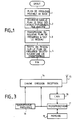
- a transceiver called master of the network searches in a basic frequency plan comprising a determined number of channels, the channels which appear to be usable. It then transmits in step 3 the plan of the channels deemed exploitable to all other transceivers on the network.
- the operation takes place in step 4, the traffic of information between all the transceivers of the network taking place in frequency evasion on the exploitable frequency levels communicated to the entire network by the master transceiver.
- step 5 the first transmitter which sends in known manner the synchronization tops to the whole network becomes the network master and searches the channels it receives from the one with the lowest reception level.
- This search is carried out for example, by measuring in the reception band of the receiver the voltage or current levels supplied by the automatic gain control circuit of the reception chain on each channel received by the receiver, retaining only the channel which gives the lowest voltage or current level Smini.
- the voltage or current level obtained is stored in step 6 and is used in step 7 to calculate a second comparison threshold S by adding a heel ⁇ S of voltage or current to the minimum threshold detected.
- the second comparison threshold S is stored in step 8.
- step 9 a frequency search is carried out in the basic frequency plan by listing those for which the corresponding voltage or current levels supplied by the device automatic gain control are included between the minimum level memorized in step 6 and the second comparison threshold calculated in step 7. If more than (N1)% of the frequencies fulfill the previous condition then sorting is performed at step 11 to determine the (N1)% of the frequencies which give the lowest current voltage levels. The corresponding frequencies are stored in step 12 to form a table of usable frequencies.
- step 10 determines whether the number of frequencies which fulfill the conditions of the tests carried out in step 9 is less than the determined number of (N1)% of the frequencies. If a new test is carried out in step 13 to compare the number of frequencies with a second number equal to (N2)% of the frequencies listed in step 9 and such that N2 is less than N1. If the number of frequencies fulfilling the condition of the test in step 9 is greater than or equal to (N2)% of the frequencies then the corresponding frequencies are stored in step 12 to constitute the table of usable frequencies.
- step 13 the number of frequencies fulfilling the condition of the test of step 9 is less than the number (N2)% of the frequencies, the method returns to the execution of steps 7 to 10 and a new threshold is calculated in step 7 by adding a new heel S to the minimum threshold stored in step 6. The process continues as long as the tests in steps 10 to 13 have not been satisfactory.
- the method described above can be modified to take account of the fact of situations where the network of transceivers can be formed by members geographically very distant from each other and subjected to jammers. different.
- the frequencies considered as exploitable could be transmitted by all or part of the members of the network at the time of initialization and that it is the concatenation of the whole which is then used to carry out the traffic. between all the members.
- FIG. 3 An embodiment of the method according to the invention in a transceiver is shown in Figure 3.
- the transceiver shown is composed in a known manner by a reception chain 14 coupled to a transmit-receive antenna 15.
- the reception chain 14 is controlled in a known manner by a frequency synthesizer 16.
- a microprocessor 17 is coupled between the reception chain 14 and the frequency synthesizer 16 through an analog to digital converter 18 which transforms the level of voltage or current supplied by the automatic gain control device internal to the reception chain 14, in digital signal samples and applies these samples to the data input port of the microprocessor 17.
- a memory 19 also coupled to the microprocessor 17 contains the program instructions necessary for the execution of the method described above using the flowcharts of FIGS. 1 and 2.
- the memory 19 also stores the decision thresholds and at the end of the analysis the table of usable frequencies.
- the memorized frequency plan is used to control the frequency switching of the frequency synthesizer 16 to allow the operation of the transceiver in frequency evasion, it is also applied to the transmission chain 14 to execute its transmission to the other transceivers on the network. This transmission takes place, for example, by assigning a number to the frequencies transmitted.
Landscapes
- Engineering & Computer Science (AREA)
- Computer Networks & Wireless Communication (AREA)
- Signal Processing (AREA)
- Mobile Radio Communication Systems (AREA)
Description
La présente invention concerne un procédé et un dispositif de transmission de l'information entre émetteurs-récepteurs radioélectriques d'un même réseau fonctionnant en évasion de fréquence.The present invention relates to a method and a device for transmitting information between radio transceivers of the same network operating in frequency evasion.
Il est connu dans le domaine des transmissions radioélectriques en haute fréquence, que l'encombrement spectral dépend des conditions de propagation et des zones géographiques au dessus desquelles s'effectuent les transmissions.It is known in the field of high frequency radio transmissions, that the spectral congestion depends on the propagation conditions and the geographic areas above which the transmissions are made.
Lorsque les conditions de propagation sont mauvaises, les récepteurs perçoivent à la fois des émissions provenant d'émetteurs proches comme d'émetteurs éloignés et la juxtaposition des signaux qui en résultent nuit à l'intelligibilité des informations utiles reçues par le récepteur.When the propagation conditions are poor, the receivers perceive both transmissions from close transmitters as distant transmitters and the juxtaposition of the signals which result from this affects the intelligibility of the useful information received by the receiver.
Le phénomène est d'autant plus sensible dans le mode de fonctionnement en évasion de fréquence, où la fréquence porteuse des informations transmises change plusieurs fois par seconde car ces modifications de fréquence ne tiennent pas compte de l'encombrement spectral. Dans ces types de fonctionnement chaque récepteur reçoit en effet en plus du signal utile, un signal parasite qui crée une gêne plus ou moins importante qui peut aller jusqu'à la perte de l'information utile lorsque le rapport entre les niveaux du signal parasite et du signal utile est élevé. Une première solution à ces difficultés est connue de la demande de brevet EP-A-0 182 762. Mais la solution qui est décrite et qui permet à deux stations radioélectriques fonctionnant en évasion de fréquence de trouver un plan de fréquence exploitable, n'est pas directement transposable à un réseau formé par plus de deux stations émettrices-réceptrices synchronisées entre elles par une station maître et éventuellement très éloignées les unes des autres.The phenomenon is all the more sensitive in the operating mode in frequency evasion, where the carrier frequency of the transmitted information changes several times per second because these frequency modifications do not take account of the spectral congestion. In these types of operation each receiver indeed receives in addition to the useful signal, a spurious signal which creates a more or less significant discomfort which can go as far as the loss of the useful information when the ratio between the levels of the spurious signal and useful signal is high. A first solution to these difficulties is known from patent application EP-A-0 182 762. But the solution which is described and which allows two radio stations operating in frequency dodging to find a usable frequency plan, is not not directly transposable to a network formed by more than two transceiver stations synchronized with each other by a master station and possibly very distant from each other.
Le but de l'invention est de pallier les inconvénients précités.The object of the invention is to overcome the aforementioned drawbacks.
A cet effet, l'invention a pour objet, un procédé de transmission de l'information entre émetteurs-récepteurs radioélectriques d'un même réseau fonctionnant en évasion de fréquence consistant
- à rechercher au moyen d'au moins un poste émetteur-récepteur un plan de fréquences exploitables,
- à transmettre le plan de fréquences exploitables aux autres émetteurs-récepteurs du réseau,
- et à effectuer les transferts des communications en évasion de fréquence sur le plan des fréquences exploitables transmis à l'ensemble des émetteurs-récepteurs du réseau, et
caractérisé en ce que la recherche d'un plan de fréquences exploitables est effectuée dans un plan de fréquences de base prédéterminé et est exécuté par l'émetteur-récepteur maître de la synchronisation dans le réseau qui effectue : une sélection dans les canaux qu'il reçoit, de celui qui présente le niveau de réception le plus faible pour déterminer un premier seuil minimum de comparaison, un calcul à partir du premier seuil d'un deuxième seuil de comparaison supérieur au premier seuil et un repérage dans les autres canaux reçus de ceux dont les niveaux de réception donnent des niveaux de comparaison correspondants compris entre le premier seuil et le deuxième seuil.To this end, the subject of the invention is a method of transmitting information between radioelectric transceivers of the same network operating in frequency evasion consisting
- to search by means of at least one transceiver station for a usable frequency plan,
- to transmit the exploitable frequency plan to the other transceivers of the network,
- and to carry out the transfers of the frequency evasion communications in terms of the exploitable frequencies transmitted to all the transceivers of the network, and
characterized in that the search for a usable frequency plan is carried out in a predetermined basic frequency plan and is executed by the master synchronization transceiver in the network which performs: a selection in the channels which it receives, from the one with the lowest reception level to determine a first minimum comparison threshold, a calculation from the first threshold of a second comparison threshold higher than the first threshold and a location in the other channels received from those the reception levels of which give corresponding comparison levels between the first threshold and the second threshold.
L'invention a également pour objet un émetteur-récepteur radioélectrique fonctionnant en évasion de fréquence comportant d'une part, une chaîne d'émission-réception pilotée par un synthétiseur de fréquence et d'autre part, un microprocesseur couplé à une mémoire, à la chaîne d'émission-réception et au synthétiseur de fréquence, comportant en outre des moyens pour permettre la recherche d'un plan de fréquences exploitables, la commande du synthétiseur de fréquence et la transmission du plan des fréquences, charactérisé en ce que la recherche du plan des fréquences exploitables est effectuée dans un plan de fréquences de base prédéterminé par le microprocesseur en sélectionnant dans les canaux de fréquence reçus celui qui présente le niveau de réception le plus faible pour déterminer un premier seuil minimum de comparaison, en calculant à partir du premier seuil un deuxième seuil de comparaison supérieur au premier seuil et en repérant dans les autres canaux reçus ceux dont les niveaux de réception donnent des niveaux de comparaison correspondants compris entre le premier seuil et le deuxième seuil.The invention also relates to a radio transceiver operating in frequency evasion comprising on the one hand, a transmission-reception chain controlled by a frequency synthesizer and on the other hand, a microprocessor coupled to a memory, the transmission-reception chain and the frequency synthesizer, further comprising means for enabling the search for a usable frequency plan, the control of the frequency synthesizer and the transmission of the plan of the frequencies, characterized in that the search for the usable frequency plan is carried out in a basic frequency plan predetermined by the microprocessor by selecting from the frequency channels received the one with the lowest reception level to determine a first minimum threshold comparison, by calculating from the first threshold a second comparison threshold greater than the first threshold and by identifying in the other channels received those whose reception levels give corresponding comparison levels between the first threshold and the second threshold.
L'invention a pour principal avantage qu'elle permet une amélioration importante de la qualité de la transmission. Elle peut être appliquée efficacement à tous les équipements tactiques haute fréquence portables ou portatifs, mobiles ou fixes où l'occupation du spectre des transmissions présente une gène considérable pour les liaisons phoniques ou numériques effectuées en évasion de fréquence.The main advantage of the invention is that it allows a significant improvement in the quality of the transmission. It can be applied effectively to all tactical high-frequency portable or portable, mobile or fixed equipment where the occupation of the spectrum of transmissions presents a considerable gene for the phonic or digital links carried out in frequency evasion.
D'autres caractéristiques et avantages de l'invention apparaîtront ci-après à l'aide de la description faite en regard des dessins annexés qui représentent :
- la figure 1 le procédé de transmission de l'information suivant l'invention sous la forme d'un organigramme ;
- la figure 2 un organigramme pour la recherche des plans de fréquences exploitables selon l'invention ;
- la figure 3 un dispositif pour la mise en oeuvre du procédé selon l'invention.
- Figure 1 the method of transmitting information according to the invention in the form of a flowchart;
- FIG. 2 a flow diagram for the search for exploitable frequency plans according to the invention;
- Figure 3 a device for implementing the method according to the invention.
Le procédé selon l'invention s'applique à la transmission de l'information dans des réseaux de transmission formés de 2 à n émetteurs-récepteurs de radio fonctionnant en évasion de fréquence aléatoire, c'est-à-dire dans un mode de transmission où les informations sont portées sur des paliers de fréquences de durées déterminées comprises par exemple entre une dizaine de millisecondes et quelques centaines de millisecondes.The method according to the invention applies to the transmission of information in transmission networks formed from 2 to n radio transceivers operating in random frequency evasion, that is to say in a transmission mode where the information is carried on frequency steps of determined durations ranging for example between ten milliseconds and a few hundred milliseconds.
Il se déroule suivant les étapes 1 à 4 de l'organigramme de la figure 1 après une phase connue et non représentée de synchronisation des émetteurs-récepteurs entre eux. Aux étapes 1 et 2 un émetteur-récepteur appelé maître du réseau recherche dans un plan de fréquences de base comprenant un nombre déterminé de canaux, les canaux qui lui paraissent exploitables. Il transmet ensuite à l'étape 3 le plan des canaux jugés exploitables à tous les autres émetteurs-récepteurs du réseau. L'exploitation a lieu à l'étape 4, le trafic des informations entre tous les émetteurs-récepteurs du réseau ayant lieu en évasion de fréquence sur les paliers de fréquence exploitables communiqués à tout le réseau par l'émetteur-récepteur maître.It takes place according to steps 1 to 4 of the flow diagram of FIG. 1 after a known and not shown phase of synchronization of the transceivers with one another. At the stages 1 and 2, a transceiver called master of the network searches in a basic frequency plan comprising a determined number of channels, the channels which appear to be usable. It then transmits in
La recherche du plan des fréquences exploitables a lieu suivant les étapes 5 à 13 du procédé représenté par l'organigramme de la figure 2. A l'étape 5, le premier émetteur qui envoie de façon connue les tops de synchronisation à tout le réseau devient le maître du réseau et fait une recherche dans les canaux qu'il reçoit de celui qui présente le niveau de réception le plus faible. Cette recherche s'effectue par exemple, en mesurant dans la bande de réception du récepteur les niveaux de tension ou de courant fournis par le circuit de commande automatique de gain de la chaîne de réception sur chaque canal reçu par le récepteur en ne retenant que le canal qui donne le niveau Smini de tension ou de courant le plus faible. Le niveau de tension ou de courant obtenu est mémorisé à l'étape 6 et est utilisé à l'étape 7 pour calculer un deuxième seuil de comparaison S en ajoutant un talon ΔS de tension ou de courant au seuil minimum détecté. Le deuxième seuil de comparaison S est mémorisé à l'étape 8. A l'étape 9 une recherche en fréquence est effectuée dans le plan de fréquences de base en répertoriant celles pour lesquelles les niveaux en tension ou en courant correspondants fournis par le dispositif de contrôle automatique de gain sont compris entre le niveau minimum mémorisé à l'étape 6 et le deuxième seuil de comparaison calcule à l'étape 7. Si plus de (N1)% des fréquences remplissent la condition précédente alors un tri est effectué à l'étape 11 pour déterminer les (N1)% des fréquences qui donnent les niveaux en tension en courant les plus faibles. Les fréquences correspondantes sont mémorisées à l'étape 12 pour former un tableau des fréquences exploitables. Par contre, si à l'étape 10 le nombre des fréquences qui remplissent les conditions des tests effectués à l'étape 9 est inférieur au nombre déterminé des (N1)% des fréquences alors un nouveau test est effectué à l'étape 13 pour comparer le nombre des fréquences à un deuxième nombre égal à (N2)% des fréquences répertoriées à l'étape 9 et tel que N2 soit inférieur à N1. Si le nombre des fréquences remplissant la condition du test de l'étape 9 est supérieure ou égale au (N2)% des fréquences alors les fréquences correspondantes sont mémorisées à l'étape 12 pour constituer le tableau des fréquences exploitables. Par contre, si à l'étape 13 le nombre des fréquences remplissant la condition du test de l'étape 9 est inférieur au nombre (N2)% des fréquences, le procédé retourne à l'exécution des étapes 7 à 10 et un nouveau seuil est calculé à l'étape 7 en ajoutant un nouveau talon S au seuil minimum mémorisé à l'étape 6. Le procédé se poursuit ainsi tant que les tests des étapes 10 à 13 n'ont pas donné satisfaction.The search for the exploitable frequency plan takes place according to
Selon une variante possible de réalisation de l'invention le procédé précédemment décrit peut être modifié pour tenir compte du fait de situations où le réseau d'émetteurs-récepteurs peut être formé par des membres géographiquement très éloignés les uns des autres et soumis à des brouilleurs différents. Dans ce cas, est possible de concevoir que les fréquences considérées comme exploitables pourront être transmises par tout ou partie des membres du réseau au moment de l'initialisation et que c'est la concaténation de l'ensemble qui est alors utilisée pour effectuer le trafic entre tous les membres.According to a possible variant embodiment of the invention, the method described above can be modified to take account of the fact of situations where the network of transceivers can be formed by members geographically very distant from each other and subjected to jammers. different. In this case, it is possible to conceive that the frequencies considered as exploitable could be transmitted by all or part of the members of the network at the time of initialization and that it is the concatenation of the whole which is then used to carry out the traffic. between all the members.
Un mode de mise en oeuvre du procédé selon l'invention dans un émetteur-récepteur est représenté à la figure 3. L'émetteur-récepteur représenté est composé de façon connue par une chaîne de réception 14 couplée à une antenne d'émission-réception 15. La chaîne de réception 14 est pilotée de façon connue par un synthétiseur de fréquence 16. Un microprocesseur 17 est couplé entre la chaîne de réception 14 et le synthétiseur de fréquence 16 au travers d'un convertisseur analogique numérique 18 qui transforme le niveau de tension ou de courant fourni par le dispositif de contrôle automatique de gain interne à la chaîne de réception 14, en échantillons numériques de signal et applique ces échantillons sur le port d'entrée des données du microprocesseur 17. Une mémoire 19 couplée également au microprocesseur 17 contient les instructions de programme nécessaires à l'exécution du procédé décrit précédemment à l'aide des organigrammes des figures 1 et 2.An embodiment of the method according to the invention in a transceiver is shown in Figure 3. The transceiver shown is composed in a known manner by a
La mémoire 19 mémorise également les seuils de décision et en fin d'analyse le tableau des fréquences exploitables. Le plan des fréquences mémorisées est utilisé pour commander la commutation en fréquence du synthétiseur de fréquence 16 pour permettre le fonctionnement de l'émetteur-récepteur en évasion de fréquence, il est également appliqué à la chaîne d'émission 14 pour exécuter sa transmission à l'ensemble des autres émetteurs-récepteurs du réseau. Cette transmission s'effectue par exemple en attribuant un numéro aux fréquences transmises.The
Claims (4)
- Process for transmitting information between radio transmitters/receivers of the same frequency-agile network consisting in- searching (2), by means of at least one transmitter/receiver post, for a plan of operable frequencies,- transmitting (3) the plan of operable frequencies to the other transmitters/receivers of the network,- and performing (4) the transfers of the frequency-agile communications regarding the operable frequency plan transmitted to the set of transmitters/receivers of the network, andcharacterized in that the search for a plan of operable frequencies is performed (1) within a predetermined base frequency plan and is executed by the transmitter/receiver piloting the synchronization in the network which performs: a selection (5), from the channels which it receives, of the one which exhibits (6) the lowest reception level in order to determine a first minimum comparison threshold, a calculation from the first threshold of a second comparison threshold greater than the first threshold and a tagging within the other channels received of those whose reception levels give corresponding comparison levels lying between the first threshold and the second threshold.
- Process according to Claim 1, characterized in that it consists in retaining (10, 11, 12) as operable channels only a limited number of channels whose reception levels are the lowest.
- Process according to either one of Claims 1 and 2, characterized in that it consists, when the transmitters/receivers of the network occupy distant geographical positions, in determining the frequencies operable by all or some of the transmitters/receivers of the network and in performing a concatenation of this set of frequencies in order to form the plan of the operable frequencies.
- Frequency-agile radio transmitter/receiver including, on the one hand, a transmission/reception chain (14) driven by a frequency synthesizer (16) and, on the other hand, a microprocessor (17) coupled to a memory (19), to the transmission/reception chain (14) and to the frequency synthesizer (16), the microprocessor being programmed with a program registered in the memory (19) in order to allow the search for a plan of operable frequencies, the control of the frequency synthesizer (16) and the transmission of the plan of the frequencies, characterized in that the search for the plan of the operable frequencies is performed within a predetermined base frequency plan by the microprocessor (17) by selecting, from the frequency channels received, the one which exhibits (6) the lowest reception level in order to determine a first minimum comparison threshold, calculating from the first threshold a second comparison threshold greater than the first threshold and tagging within the other channels received those whose reception levels give corresponding comparison levels lying between the first threshold and the second threshold.
Applications Claiming Priority (2)
| Application Number | Priority Date | Filing Date | Title |
|---|---|---|---|
| FR8906104 | 1989-05-10 | ||
| FR898906104A FR2646977B1 (en) | 1989-05-10 | 1989-05-10 | METHOD AND DEVICE FOR TRANSMITTING INFORMATION BETWEEN RADIO TRANSCEIVERS OF THE SAME NETWORK OPERATING IN FREQUENCY ESCAPE |
Publications (2)
| Publication Number | Publication Date |
|---|---|
| EP0397546A1 EP0397546A1 (en) | 1990-11-14 |
| EP0397546B1 true EP0397546B1 (en) | 1994-12-14 |
Family
ID=9381525
Family Applications (1)
| Application Number | Title | Priority Date | Filing Date |
|---|---|---|---|
| EP90401186A Expired - Lifetime EP0397546B1 (en) | 1989-05-10 | 1990-05-02 | Method and apparatus for information transmission between radio transceivers of the same frequency hopping network |
Country Status (7)
| Country | Link |
|---|---|
| US (1) | US5214788A (en) |
| EP (1) | EP0397546B1 (en) |
| CA (1) | CA2016374A1 (en) |
| DE (1) | DE69014984T2 (en) |
| ES (1) | ES2064678T3 (en) |
| FR (1) | FR2646977B1 (en) |
| GR (1) | GR3015073T3 (en) |
Families Citing this family (23)
| Publication number | Priority date | Publication date | Assignee | Title |
|---|---|---|---|---|
| DE69333117T2 (en) * | 1993-05-27 | 2004-04-01 | Axonn, L.L.C. | RADIO WITH FREQUENCY JUMP |
| US5621767A (en) * | 1994-09-30 | 1997-04-15 | Hughes Electronics | Method and device for locking on a carrier signal by dividing frequency band into segments for segment signal quality determination and selecting better signal quality segment |
| US6240126B1 (en) * | 1996-09-18 | 2001-05-29 | Brother Kogyo Kabushiki Kaisha | Wireless communication device |
| US6871180B1 (en) * | 1999-05-25 | 2005-03-22 | Arbitron Inc. | Decoding of information in audio signals |
| JP2005531202A (en) | 2002-06-21 | 2005-10-13 | ワイデファイ インコーポレイテッド | Wireless local area network repeater |
| US8885688B2 (en) | 2002-10-01 | 2014-11-11 | Qualcomm Incorporated | Control message management in physical layer repeater |
| WO2004038958A1 (en) * | 2002-10-24 | 2004-05-06 | Widefi, Inc. | Wireless local area network repeater with in-band control channel |
| AU2003274992A1 (en) * | 2002-10-11 | 2004-05-04 | Widefi, Inc. | Reducing loop effects in a wireless local area network repeater |
| US8060009B2 (en) * | 2002-10-15 | 2011-11-15 | Qualcomm Incorporated | Wireless local area network repeater with automatic gain control for extending network coverage |
| US8078100B2 (en) | 2002-10-15 | 2011-12-13 | Qualcomm Incorporated | Physical layer repeater with discrete time filter for all-digital detection and delay generation |
| US7230935B2 (en) | 2002-10-24 | 2007-06-12 | Widefi, Inc. | Physical layer repeater with selective use of higher layer functions based on network operating conditions |
| CN100588133C (en) * | 2002-11-15 | 2010-02-03 | 高通股份有限公司 | Wireless local area network repeater with detection |
| JP2006510326A (en) * | 2002-12-16 | 2006-03-23 | ワイデファイ インコーポレイテッド | Improved wireless network repeater |
| US8027642B2 (en) | 2004-04-06 | 2011-09-27 | Qualcomm Incorporated | Transmission canceller for wireless local area network |
| WO2005115022A2 (en) * | 2004-05-13 | 2005-12-01 | Widefi, Inc. | Non-frequency translating repeater with detection and media access control |
| CN1985528B (en) * | 2004-06-03 | 2010-06-09 | 高通股份有限公司 | Frequency translating repeater with low cost and high performance local oscillator architecture |
| WO2006081405A2 (en) * | 2005-01-28 | 2006-08-03 | Widefi, Inc. | Physical layer repeater configuration for increasing mino performance |
| DE102005023166B4 (en) * | 2005-05-19 | 2007-09-27 | Siemens Ag | Method for monitoring the function of medical accelerators and medical accelerator |
| EP2002565A4 (en) * | 2006-03-31 | 2012-07-04 | Qualcomm Inc | Enhanced physical layer repeater for operation in wimax systems |
| FR2900009B1 (en) * | 2006-04-14 | 2008-06-20 | Thales Sa | METHOD AND DEVICE FOR ANTI-INTERFERENCE CONTROL IN A TELECOMMUNICATIONS SYSTEM |
| RU2444159C2 (en) | 2006-09-21 | 2012-02-27 | Квэлкомм Инкорпорейтед | Method and device for suppression of oscillations between repeaters |
| CN101529741B (en) | 2006-10-26 | 2017-04-26 | 高通股份有限公司 | Repeater techniques for multiple input multiple output utilizing beam formers |
| US11483714B2 (en) | 2019-03-20 | 2022-10-25 | Raytheon Company | Intelligent spectrum control methods and systems |
Family Cites Families (6)
| Publication number | Priority date | Publication date | Assignee | Title |
|---|---|---|---|---|
| DE3415032C2 (en) * | 1983-04-27 | 1985-06-20 | Siemens AG, 1000 Berlin und 8000 München | Method for interference-resistant radio transmission |
| SE445698B (en) * | 1984-11-19 | 1986-07-07 | Ericsson Telefon Ab L M | PROCEDURE TO REDUCE THE IMPACT OF SMALL-STANDARD STORARS IN RADIO COMMUNICATION BETWEEN TWO STATIONS, WHICH USE FREQUENCY HOPE |
| US4794635A (en) * | 1986-11-28 | 1988-12-27 | Motorola, Inc. | Two-way radio communication system with max-minimum call assignment method |
| DE3700070A1 (en) * | 1987-01-02 | 1988-07-14 | Eberspaecher J | DEVICE FOR CATALYTIC CLEANING OF VEHICLE ENGINE EXHAUST GAS |
| GB2203314B (en) * | 1987-04-01 | 1991-03-06 | Plessey Co Plc | Frequency hopping assignment arrangement for frequency hopping radio stations |
| US4872205A (en) * | 1987-08-21 | 1989-10-03 | American Telephone And Telegraph Company | Radio communication system having autonomously selected transmission frequencies |
-
1989
- 1989-05-10 FR FR898906104A patent/FR2646977B1/en not_active Expired - Fee Related
-
1990
- 1990-05-02 EP EP90401186A patent/EP0397546B1/en not_active Expired - Lifetime
- 1990-05-02 ES ES90401186T patent/ES2064678T3/en not_active Expired - Lifetime
- 1990-05-02 DE DE69014984T patent/DE69014984T2/en not_active Expired - Fee Related
- 1990-05-04 US US07/519,115 patent/US5214788A/en not_active Expired - Fee Related
- 1990-05-09 CA CA002016374A patent/CA2016374A1/en not_active Abandoned
-
1995
- 1995-02-16 GR GR940404125T patent/GR3015073T3/en unknown
Also Published As
| Publication number | Publication date |
|---|---|
| DE69014984T2 (en) | 1995-05-04 |
| CA2016374A1 (en) | 1990-11-10 |
| FR2646977B1 (en) | 1994-07-29 |
| ES2064678T3 (en) | 1995-02-01 |
| FR2646977A1 (en) | 1990-11-16 |
| EP0397546A1 (en) | 1990-11-14 |
| DE69014984D1 (en) | 1995-01-26 |
| GR3015073T3 (en) | 1995-05-31 |
| US5214788A (en) | 1993-05-25 |
Similar Documents
| Publication | Publication Date | Title |
|---|---|---|
| EP0397546B1 (en) | Method and apparatus for information transmission between radio transceivers of the same frequency hopping network | |
| EP1998469B1 (en) | Opportunistic radio terminal and corresponding method for band searching | |
| US7218934B2 (en) | Mobile station speed estimation | |
| US5428647A (en) | Method and apparatus for synchronizing a received signal in a digital radio communication system | |
| FR2706709A1 (en) | Synchronization method for code division multiple access radiotelephone communications. | |
| FR2566562A1 (en) | CELLULAR MOBILE RADIOTELEPHONY SYSTEM | |
| FR2766320A1 (en) | METHOD AND DEVICE FOR ANALYZING INTERFERENCE IN A CELLULAR RADIO COMMUNICATION SYSTEM | |
| EP0735702A1 (en) | Method and apparatus for base station diversity reception in a mobile communications system | |
| FR2758673A1 (en) | SELF-ADAPTIVE DATA TRANSMISSION METHOD AND DEVICE FOR IMPLEMENTING SAME | |
| EP2612166A1 (en) | Method and device for locating at least one obstacle in a communication network, corresponding computer program | |
| EP1305921A1 (en) | Method for processing a digital input signal of a channel equalizer | |
| WO1997047150A1 (en) | Method and device for the management of radiocommunication intercell handovers in a cellular radiocommunication system | |
| FR2763195A1 (en) | METHOD AND DEVICE FOR PERFORMING A COMMUNICATION PASS BETWEEN COMMUNICATION SYSTEMS HAVING DIFFERENT SCHEMES WITH MULTIPLE ACCESS | |
| EP2577876B1 (en) | Method and network for transmitting information between a plurality of radioelectric stations | |
| EP0048200B1 (en) | Tuning-frequency search device for a frequency-modulation radio receiver | |
| FR2721466A1 (en) | Control signal for receivers, synchronization device, equalization device, synchronization method and corresponding receivers. | |
| FR2527872A1 (en) | FIXED STATION OF A RADIOCOMMUNICATION SYSTEM WITH FREQUENCY HOPPING AND BANALIZED TRANSMITTERS | |
| EP0693247B1 (en) | Synchronization device for a radio communication system terminal | |
| EP2605423A2 (en) | Satellite transmission system with commutation between low, medium and high data rate signals according to interference conditions. | |
| EP0082055B1 (en) | Method of establishing communications in a transceiver network using frequency hopping, and apparatus for carrying out this method | |
| EP2561623B1 (en) | Method and device for determining a set of frequencies that can be used for transmitting information between radio transceivers of a network operating with frequency hopping | |
| FR2777402A1 (en) | METHOD AND SYSTEM FOR REDUCING INTERFERENCE | |
| EP2056527A1 (en) | Frequency band selection in a telecommunications network | |
| Chandler et al. | Development and evaluation of an LPI figure of merit for direct-sequence and frequency-hop systems | |
| EP1221792A1 (en) | Method and receiver for adaptive estimation of space and time parameters of a propagation channel |
Legal Events
| Date | Code | Title | Description |
|---|---|---|---|
| PUAI | Public reference made under article 153(3) epc to a published international application that has entered the european phase |
Free format text: ORIGINAL CODE: 0009012 |
|
| AK | Designated contracting states |
Kind code of ref document: A1 Designated state(s): DE ES GB GR IT |
|
| 17P | Request for examination filed |
Effective date: 19910429 |
|
| 17Q | First examination report despatched |
Effective date: 19930713 |
|
| RAP1 | Party data changed (applicant data changed or rights of an application transferred) |
Owner name: THOMSON-CSF |
|
| GRAA | (expected) grant |
Free format text: ORIGINAL CODE: 0009210 |
|
| AK | Designated contracting states |
Kind code of ref document: B1 Designated state(s): DE ES GB GR IT |
|
| ITF | It: translation for a ep patent filed |
Owner name: JACOBACCI CASETTA & PERANI S.P.A. |
|
| REF | Corresponds to: |
Ref document number: 69014984 Country of ref document: DE Date of ref document: 19950126 |
|
| REG | Reference to a national code |
Ref country code: ES Ref legal event code: FG2A Ref document number: 2064678 Country of ref document: ES Kind code of ref document: T3 |
|
| GBT | Gb: translation of ep patent filed (gb section 77(6)(a)/1977) |
Effective date: 19950208 |
|
| REG | Reference to a national code |
Ref country code: GR Ref legal event code: FG4A Free format text: 3015073 |
|
| PLBE | No opposition filed within time limit |
Free format text: ORIGINAL CODE: 0009261 |
|
| STAA | Information on the status of an ep patent application or granted ep patent |
Free format text: STATUS: NO OPPOSITION FILED WITHIN TIME LIMIT |
|
| 26N | No opposition filed | ||
| PGFP | Annual fee paid to national office [announced via postgrant information from national office to epo] |
Ref country code: GR Payment date: 19980415 Year of fee payment: 9 |
|
| PG25 | Lapsed in a contracting state [announced via postgrant information from national office to epo] |
Ref country code: GR Free format text: LAPSE BECAUSE OF NON-PAYMENT OF DUE FEES Effective date: 19990531 |
|
| PGFP | Annual fee paid to national office [announced via postgrant information from national office to epo] |
Ref country code: ES Payment date: 20000510 Year of fee payment: 11 |
|
| PG25 | Lapsed in a contracting state [announced via postgrant information from national office to epo] |
Ref country code: ES Free format text: LAPSE BECAUSE OF NON-PAYMENT OF DUE FEES Effective date: 20010503 |
|
| REG | Reference to a national code |
Ref country code: GB Ref legal event code: IF02 |
|
| PGFP | Annual fee paid to national office [announced via postgrant information from national office to epo] |
Ref country code: GB Payment date: 20020419 Year of fee payment: 13 Ref country code: DE Payment date: 20020419 Year of fee payment: 13 |
|
| PG25 | Lapsed in a contracting state [announced via postgrant information from national office to epo] |
Ref country code: GB Free format text: LAPSE BECAUSE OF NON-PAYMENT OF DUE FEES Effective date: 20030502 |
|
| REG | Reference to a national code |
Ref country code: ES Ref legal event code: FD2A Effective date: 20030303 |
|
| PG25 | Lapsed in a contracting state [announced via postgrant information from national office to epo] |
Ref country code: DE Free format text: LAPSE BECAUSE OF NON-PAYMENT OF DUE FEES Effective date: 20031202 |
|
| GBPC | Gb: european patent ceased through non-payment of renewal fee |
Effective date: 20030502 |
|
| PG25 | Lapsed in a contracting state [announced via postgrant information from national office to epo] |
Ref country code: IT Free format text: LAPSE BECAUSE OF NON-PAYMENT OF DUE FEES;WARNING: LAPSES OF ITALIAN PATENTS WITH EFFECTIVE DATE BEFORE 2007 MAY HAVE OCCURRED AT ANY TIME BEFORE 2007. THE CORRECT EFFECTIVE DATE MAY BE DIFFERENT FROM THE ONE RECORDED. Effective date: 20050502 |