EP0396103A2 - Channel selecting apparatus - Google Patents
Channel selecting apparatus Download PDFInfo
- Publication number
- EP0396103A2 EP0396103A2 EP90108272A EP90108272A EP0396103A2 EP 0396103 A2 EP0396103 A2 EP 0396103A2 EP 90108272 A EP90108272 A EP 90108272A EP 90108272 A EP90108272 A EP 90108272A EP 0396103 A2 EP0396103 A2 EP 0396103A2
- Authority
- EP
- European Patent Office
- Prior art keywords
- channel
- local oscillation
- frequency
- above mentioned
- data corresponding
- Prior art date
- Legal status (The legal status is an assumption and is not a legal conclusion. Google has not performed a legal analysis and makes no representation as to the accuracy of the status listed.)
- Granted
Links
Images


Classifications
-
- H—ELECTRICITY
- H03—ELECTRONIC CIRCUITRY
- H03J—TUNING RESONANT CIRCUITS; SELECTING RESONANT CIRCUITS
- H03J7/00—Automatic frequency control; Automatic scanning over a band of frequencies
- H03J7/18—Automatic scanning over a band of frequencies
-
- H—ELECTRICITY
- H03—ELECTRONIC CIRCUITRY
- H03J—TUNING RESONANT CIRCUITS; SELECTING RESONANT CIRCUITS
- H03J1/00—Details of adjusting, driving, indicating, or mechanical control arrangements for resonant circuits in general
- H03J1/0008—Details of adjusting, driving, indicating, or mechanical control arrangements for resonant circuits in general using a central processing unit, e.g. a microprocessor
- H03J1/0041—Details of adjusting, driving, indicating, or mechanical control arrangements for resonant circuits in general using a central processing unit, e.g. a microprocessor for frequency synthesis with counters or frequency dividers
- H03J1/005—Details of adjusting, driving, indicating, or mechanical control arrangements for resonant circuits in general using a central processing unit, e.g. a microprocessor for frequency synthesis with counters or frequency dividers in a loop
Definitions
- This invention relates to a channel selecting apparatus to be used for CATV receivers and television receivers.
- the CATV is multi-channeled to diversify the television service.
- a multi-channel CATV system realizing the transmission exceeding 100 channels is operated and a channel selecting system including a tuner so that the receiver may also correspond to it is designed.
- the channel number is continuously sequentially switched. That is to say, the channel number is sequentially made to rise up to a larger number from a smaller number or to fall down reversely to a smaller number from a larger number to select a desired channel. This is called an up/down channel selecting system.
- this up/down channel selecting system in order to elevate the operatability it is generally set to move to the next channel by skipping over a channel not broadcasting at the time of selecting the channel or a channel in which no receiving is desired. That is to say, it is preset to skip the channel.
- the number of the channel desired to be selected is memorized in the address position corresponding to this channel number of a memory (RAM), a region in which the information as to whether this channel is skipped or not is written, that is, a skip flag is set and the skip information of each channel is memorized in the skip flag.
- a total of 181 CH of 1 to 125 CH (CH is an abbreviatin of the channel here and also hereinafter) of the CATV and 14 to 69 CH of the UHF of the TV are made to correspond to position numbers 1 to 181 and are provided respectively with skip flags.
- CH is an abbreviatin of the channel here and also hereinafter
- the case of this example is based on the actual state of the United States of America and 2 to 13 CH of the VHF of the TV and 2 to 13 CH of the CATV are of substantially the same frequency and the same positions.
- the present invention is to eliminate the above mentioned problems and has it as an object to provide channel selecting apparatus wherein the number of skip flags can be made small and the memory (RAM) capacity of the microcomputer can be effectively utilized.
- the present invention is a channel selecting apparatus comprising a tuner whereby a high frequency signal is mixed with a local oscillation signal controlled by a tuning voltage so as to be converted to an intermediate frequency signal to receive a signal of a desired channel and a controlling means whereby data corresponding to a local oscillation frequency are output in each channel on the basis of a channel-up or channel-down channel selecting operation, a tuning voltage is prepared by using these data and the local oscillation frequency of the above mentioned tuner is controlled, wherein the information as to whether the selection of each channel is to be inhibited or permitted at the time of the channel-up or channel-down channel selection is memorized in the above mentioned controlling means and a common channel selection inhibiting information memorizing means is provided for a plurality of channels not allowed to exist simultaneously.
- Fig. 3 is an explanatory view for explaining a skip flag set in the channel selecting apparatus according to the present invention and its memory capacity.
- the skip flags are made common, because, for example, in the United States of America (which shall be mentioned merely as US hereinafter), CATV 2 to 13CH and UHF 2 to 13CH of TV are of the same frequency on the same channel number.
- CATV 65 to 94CH UHF 14 to 43CH of TV and CATV 100 to 125, UHF 44 to 69CH of TV in US, as in, for example, CATV 125CH (of a video carrier frequency of 799.25 MH z ) and UHF 69CH ( of a video carrier frequency of 801.25 MH z )
- the respective channel center frequencies are separated from each other only by 2 MH z
- the signals will be mixed if broadcast simultaneously (that is to say, in the M-NTSC system adopted in US, the sole frequency band of one channel is of 6 MH z , whereas the frequency distance between the above mentioned two channels is only 2 MH z ) and therefore the skip flags are made common. If the skip flags are thus made common between 1 to 125CH of CATV and CH of VHF and UHF of TV, a memory capacity for 56 bits will be able to be saved as compared with the conventional example in Fig. 6.
- the receiving channels are set as fixed to 1 to 1 in response to the position numbers and it is judged by using skip flags whether a skip is made or not
- CATV 2 to 13CH and VHF 2 to 13CH of TV will be made to correspond to the position numbers 2 to 13 and CATV 65 to 94CH
- 100 to 125CH and UHF 14 to 69CH of TV will be made to correspond to the position numbers 65 to 94 and 100 to 125. Therefore, the position numbers may be 1 to 125 corresponding to which skip flags of 125 bits may be provided.
- channel selecting apparatus provided with an AFT (automatic fine tuning) detector
- AFT automatic fine tuning
- the skip flags can be made common in VHF 2 to 13CH and UHF 14 to 69CH of TV and in CATV 2 to 13 and CATV 65 to 94 and 100 to 125CH.
- Fig. 1 is a block diagram showing an embodiment of the channel selecting apparatus according to the present invention.
- the embodiment in Fig. 1 shows a channel selecting apparatus of a frequency synthesizer system.
- this channel selecting apparatus By the way, in the receiver in which this channel selecting apparatus is used, both CATV and TV signals can be received by using the same tuner.
- a TV or CATV high frequency signal (which shall be mentioned as an RF signal hereinafter) is input from an antenna or the like not illustrated.
- This RF signal is fed to a tuner 2 comprising a frequency converter 21 and a voltage controlled oscillator (which shall be mentioned as a VCO hereinafter) 22.
- the frequency converter 21 converts the input RF signal to an intermediate frequency signal (which shall be mentioned as an IF signal hereinafter) by a local oscillation frequency from the VCO 22 which generates a local oscillation frequency fOSC corresponding to a tuning voltage fed from a PLL part 5.
- the above mentioned IF signal is fed to a demodulating circuit 4 through a band pass filter (which shall be mentioned as a BPF hereinafter) 3.
- a TV or CATV demodulating output is obtained from the demodulating circuit 4.
- a central operation processing apparatus (which shall be mentioned as an MPU hereinafter) 6 generates data fOSC* (digital data delivered by the MPU 6 and represented by a local oscillation frequency expression) corresponding to the local oscillatiion frequency for each channel on the basis of the up or down input of the channel (that is, the position) or the CATV/TV switching input from a key input means not illustrated and feeds them to the PLL part 5.
- the MPU 6 will judge whether a skip is to be made or not for each channel with reference to an internal skip flag memory (See Fig. 2) at the up and down time of the channel.
- the MPU 6 has a function of displaying the channel number and displaying being of the CATV at the up and down time of the channel.
- the above mentioned PLL part 5 comprises a programable divider 51, a reference oscillator 52 and a phase detector 53.
- the programable divider 51 is a variable frequency divider dividing the local oscillation frequency fOSC from the VCO 22 by the control signal fOSC* from the MPU 6.
- the reference oscillator 52 is formed of a crystal oscillator and generates a reference oscillation frequency f ref.
- the phase detector 53 compares the phases of the reference oscillation output f ref and the frequency dividing output fo of the programable divider 51 and operates so that, when the phase of fo advances more than f ref, the output will lower.
- This output is a voltage output and is fed to the VCO 22 which is so formed that, when the input voltage increases, the oscillation frequency will increase. Therefore, as a result, the loop of the VCO 22, programable divider 51, reference oscillator 52 and phase detector 53 will become a PLL (phase synchronizing loop).
- PLL phase synchronizing loop
- fOSC operates to be equal to fOSC*. Therefore, if fOSC* is delivered from the MPU 6, the local oscillation frequency fOSC of the VCO 22 will be able to be set at any desired value.
- Fig. 2 is an internal block diagram of the MPU in Fig. 1. This diagram is explained on the case that the CATV/TV switching input is a CATV input.
- the channel up or channel down input is fed to an operation circuit 61 to which are connected a first position memory 62 memorizing 1 position (that is, 1CH) which is the first position of the CATV at the CATV receiving time and a last position memory 63 memorizing 125 position (that is, 125CH) which is the last position of the CATV.
- a first position memory 62 memorizing 1 position (that is, 1CH) which is the first position of the CATV at the CATV receiving time
- a last position memory 63 memorizing 125 position (that is, 125CH) which is the last position of the CATV.
- a channel number memory 64 memorizing channel number data corresponding to the position numbers 1 to 125 of the CATV
- a skip flag memory 65 memorizing the information as to whether a skip is to be made or not at the up/down channel selecting time on the respective channels of the CATV
- a stop position memory 66 to be used to judge (in the step S4 in Fig. 4) whether the skip flag is to be pulled out of the reference loop (closed loop of the steps S2 to S5 in Fig. 4) or not when the information to be skipped is memorized in the skip flag memory 65 corresponding to all the positions.
- the stop position memory 66 the position number, for example, up by 1 from the present position number (in the step S1 in Fig.
- a position number memory 67 memorizing position numbers and an fOSC* memory memorizing data of fOSC* corresponding to the channel numbers.
- a channel to be selected when a channel-up or channel-down input is received, a channel to be selected will be judged without skipping with reference to the skip flag memory 65, the judged selected channel will be memorized in the position number memory 67, data corresponding to this channel will be read out of the channel number memory 64, data fOSC* corresponding to the local oscillation frequency corresponding to the channel number will be prepared with reference to the fOSC* memory and will be output to the PLL part 5 and the channel number display data will be output.
- Fig. 4 shows an example of a key operating part (remote controlled hand unit) to be used to feed a CH-up input, CH-down input and CATV/TV switching input to the MPU 6.
- This key operating part is provided with not only a power source key (POWER) switching on/off the power source of the receiver, CATV/TV key switching the CATV/TV, up-channel selecting key (CHANNEL UP) for the CH-up channel selection and down-channel selecting key (CHANNEL DOWN) for the CH-down channel selection but also ten keys 0 to 9 to be used for the direct channel selection or the like by inputting the channel number into the key and further presetting keys (MEMORY, ADD, ERASE) for memorizing in the skip flag memory 65 the information as to whether skipped or not at the time of up/down-selecting the respective channels of the CATV (or TV).
- POWER power source key
- CATV/TV key switching the CATV/TV
- up-channel selecting key CHANNEL UP
- the MEMORY key is an automatically preset auto-key so that, when it is pushed, the respective channels of the CATV (or TV) will be automatically sequentially switched, or so-called searched, the information of selecting the channel in which the signal is present will be memorized (that is to say, the skip-off information will be memorized) and the information of skipping the channel having no signal will be memorized (that is to say, the skip-on information will be memorized).
- the ADD and ERASE keys are manual keys for the user to manually memorize in the skip flag memory 65 whether the respective channels of the CATV (or TV) are to be skipped or not.
- CATV 94CH and UHF 43CH have a skip flag in common and therefore, in case the skip flag is on as described above and then CATV 94CH is switched to the TV reception, the skip flag will be on even on UHF 43CH.
- the information as to whether the respective channels of the VHF and UHF are to be automatically or manually skipped or not will be able to be memorized.
- Fig. 5 is a flow chart showing the operation of the MPU when channels are up-selected in the CATV.
- the position number will be increased by 1 whenever the key is pushed.
- an operation of making the position number the first position will be made.
- this operation will be made in the operation circuit 61 by referring to the first position memory 62 and last position memory 63.
- the step S4 is a step wherein, when the skip flag 1 stands in all the positions, it will be judged whether the skip flag will be pulled out of the reference loop or not.
- step S5 in the process in which the position number is up, the value of the skip flag corresponding to the value of the position number memory 67 is judged. If the skip flag is on (that is, 1), the program will return to the step S2 and the position number will be automatically skipped to the next number. In the step S5, if the skip flag is off (that is, 0), as shown in the steps S6, S7 and S8 the value of the data fOSC* corresponding to the local oscillation frequency corresponding to the position number then will be determined and output and the respective data of the CATV display and channel number display will be output.
- the operations of the steps S5, S6 and S7 are as explained in Fig. 2.
- a skip flag will be used in common and therefore the number of skip flags can be small. Therefore, the memory (RAM) capacity of the channel selecting microcomputer can be effectively utilized.
- an IFAGC amplifying circuit 7 and size judging circuit 8 are provided between the BPF 3 and MPU 6 in Fig. 6.
- the size judging circuit is a so-called AFT circuit.
- the frequency dividing ratio of the programable divider 51 is set by the data fOSC* from the MPU 6 in which, when the channel to be selected is designated by the user, the frequency dividing ratio will be renewed sequentially at a predetermined period from a frequency dividing ratio so that the frequency (tuned frequency fTUNE) of the local oscillation signal may be sequentially switched within a fixed range (tuned frequency range) from a tuned frequency (which shall be mentioned as a search starting frequency hereinafter) and may be continuously searched.
- the renewal of the frequency dividing ratio of the above mentioned programable divider 51 is controlled according to the size relation between the input signal frequency fIN and search starting tuning frequency fS. That is to say, the IF signal output from the BPF 3 is amplified and controlled to be of a fixed amplitude by the IFAGC amplifying circuit 7. This amplified controlled output is fed to the size judging circuit 8.
- the frequency fIF of the IF signal fed to this size judging circuit 8 will be different from the inherent intermediate frequency f01 in case the input signal frequency fIN is different from the prescribed frequency.
- the size judging circuit 8 judges the sizes of this inherent intermediate frequency f01 and the actual intermediate frequency fIF at the time of starting the search to judge the size relation between the input signal frequency fIN and search starting tuned frequency fS.In this case, as shown in Fig. 7, in case the actual intermediate frequency fIN at the time of starting the search, that is, the search starting tuned frequency fS is larger than the input signal frequency fIN, the size judging circuit 8 will output a high level judging signal VDP. On the other hand, in the case reverse to this, a low level judging signal VDP will be output.
- the search starting tuned frequency fS will be larger than the input signal frequency fIN and therefore, as shown in Fig. 8, the above mentioned MPU 6 wil renew the frequency dividing ratio of the programable divider 51 in the direction of lowering the tuned frequency fTUNE.
- the search starting tuned frequency fS will be smaller than the input signal frequency fIN and therefore, as shown in Fig. 9, the frequency dividing ratio of the programable divider 51 will be renewed in the direction of elevating the tuned frequency fTUNE.
- Fig. 10 shows the case that the search starting tuned frequency fS is larger than the input signal frequency fIN.
- the channel selecting apparatus provided with such AFT circuit as in this embodiment can be applied also to the case that the input signal frequency fIN is offset from the prescribed frequency, for example, as in the HRC (Harmonic Related Carriers) and IRC (Incremental Related Carriers) of the CATV in US.
- HRC Harmonic Related Carriers
- IRC Intelligent Related Carriers
- the apparatus shown in Fig. 11 is considered as another example of an apparatus wherein, in the apparatus shown in Fig. 1, in the case of selecting an object channel by the up/down channel selection, even if the input signal frequency of the channel is different from the normal frequency, it will be automatically searched and the skip information will be able to be memorized in the skip flag memory.
- an AFT detector 9 is provided between the BPF 3 and MPU 6 in Fig. 1.
- the frequency variation of the IF signal from the BPF 3 is taken out as a direct current voltage variation and whether the IF frequency is higher or lower than a predetermined value is transmitted to the MPU 6. That is to say, the AFT detector 9 outputs an AFT voltage VAFT and the MPU 6 controls fOSC* (local oscillation frequency expressing data delivered by the MPU) and searches a frequency f02 in which the VAFT will vary to be on a logical level "0" (0V) from a logical level "1" (5V) when fOSC* is elevated.
- fOSC* local oscillation frequency expressing data delivered by the MPU
- Fig. 13 shows detection characteristics of an AFT detector 9 for an actual television signal.
- Fig. 13 shows variations of VAFT against the variations of fOSC* P
- C and S represent lead-in positions of the AFT repectively by the video carrier, color sub-carrier and sound carrier of the desired channel.
- S-1 and C-1 represent lead-in positions respectively by the sound carrier and color sub-carrier of the lower adjacent channel.
- P+1 represents a lead-in position by the video carrier of the upper adjacent channel.
- the downward directed and upward directed arrows represent respectively the directions of the variation of VAFT when fOSC* is increased.
- the VAFT varies upward. That is to say, it is shown that the rising position fluctuates substantially within this hatched range.
- the downward variation is in only the position in which each carrier is present. The AFT is led into this position.
- the operation circuit 61 within the MPU 6 is formed as shown in Fig. 14 so that the normal reception may be possible. That is to say, in the process of searching the frequency f02 corresponding to the video carrier P, it is detected whether the AFT is led into the objective video carrier P, into the sound carrier S-1 of the lower adjacent channel or into the color sub-carrier C and, in case it is led into the carrier S-1 or carrier C, the video carrier P will be searched again.
- Fs and -Fc represent means whereby in order to search the carrier P again at the time of detecting respectively the carrier S-1 and carrier C, data of a fixed frequency to be increased or decreased from the value of fOSC* then are generated so that, at the time of detecting the carrier S-1 or carrier C, the FS or -FC may be switched by a switching circuit 31 and the fixed frequency FS or -FC may be fed to an adder 32 at one input end.
- the value fOSC1 of fOSC* set at the fOSC* memory 33 then is fed to the adder 32 at the other input end.
- the above mentioned 250 KH z is a value taking into consideration the above described fluctuation of 125 KH z of the frequency difference between the channels and the fluctuation of the AFT circuit.
- the value of FC may be about 3.31 MH z in the M-NTSC system.
- 3.31 MH z (Color sub-carrier frequency of 3.579545 MH z ) - 250 KH z .
- a controlling circuit 43 loads an fOSC* memory 33 from an fOSC (EXPE) memory 41 with fixed frequency data corresponding to a desired channel.
- the frequency data fOSC* are converted to a voltage value V2 (fOSC*) by a converter 36 to switch the channel.
- An AFT detector 4 outputs an AFT voltage VAFT corresponding to V2 (fOSC*).
- An AFT controller 39 operates an AFT loop to search f02. When the AFT is led in, the AFT controller 39 will switch the switching circuit 37 to the b side so that an S-1 carrier lead-in detector 34 and carrier lead-in detector 35 may function.
- Whether the AFT is detected by the S-1 carrier lead-in detector 34 or by the C carrier lead-in detector 35 depends on whether the value of fOSC* then is on the sound carrier S-1 side of the lower adjacent channel of each channel or on the color sub-carrier C side of each channel.
- the S-1 carrier lead-in detector 34 switches the switching circuit 31 to a data generating means FS with its controlling output, stores the value of the fOSC* memory 33 then once in an fOSC1 memory 42 and then increases the value of the fOSC* memory 33 by the predetermined frequency FS. Then, the AFT is measured and, when the VAFT is "0", the carrier P will have been detected and therefore the AFT will be judged to have been led into the carrier S-1 at fOSC. In this case, if the carrier is searched again from the value of the fOSC* memory 33 then, that is, fOSC1 + FS, the AFT will be able to be led into the P carrier.
- the switching circuit 37 is switched to the a side to make a search with F STEP data.
- the operation of the switching circuit 38 switching the data memories nF STEP and -nF STEP is the same as in the switching circuit 25 of the prior art example (Fig. 10). If VAFT "0" is not detected in fOSC1 + FS, fOSC1 will be judged to be a carrier P and the value of the fOSC1 memory 32 will be returned to the fOSC* memory 33.
- the C carrier lead-in detector 35 switches the switching circuit 31 to the data generating means -FC with its controlling output, transfers the value of the fOSC* memory 33 then to fOSC1 decreases the value of fOSC* by the predetermined frequency FC. Then the AFT is measured and, when the VAFT is "0", the carrier P will have been detected and therefore the AFT will be judged to have been led into the carrier C at the value fOSC1 of fOSC*. The same as in the case of S-1, if the switching circuit 37 is switched to the a side and the carrier P is searched by the F STEP unit from the carrier fOSC1-FC, the AFT will be able to be led into the carrier P. If VAFT "0" is not detected in fOSC1-FC, fOSC1 will be considered to have been the carrier P and fOSC* will be returned to fOSC1.
- Fig. 15 is to explain an example of the operation of the circuit in Fig. 14. Time is taken on the abscissa and fOSC* is taken on the ordinate. At first, the value of fOSC* is made fOSC1-FC to detect a carrier C. Then, the value of fOSC* is made fOSC1 + FS to detect a carrier S-1. In this case, as the AFT is not led into the carriers C and S-1, the value of fOSC* is returned to fOSC1.
- Fig. 16 is to explain another example of the operation of the circuit in Fig. 14 and shows the case of only detecting the carrier S-1.
- the value of fOSC* is made fOSC1 + FS to detect the carrier S-1.
- the value of fOSC* is returned to fOSC1.
- the frequency differences between S-1 and P and between P and C are utilized and therefore the video carrier P can be discriminated without resorting to a CATV transmitting system (that is, without resorting to the absolute frequency of the video carrier P).
- an automatic channel selection by detecting signals is made possible without causing a mis-operation of selecting channels by leading the AFT into the sound carrier of the lower adjacent channel or the color sub-carrier of the desired channel.
- the detecting characteristics of the AFT detector 9 will be as shown in Fig. 13 but, in case there is no broadcast signal in the desired channel, the characteristics of the AFT detector will be as shown in Fig. 17. It is shown that, in this case, when ⁇ fOSC* is 1.5 MHz, the AFT will be led into spurious I.
- a controlling circuit 71 feeds fixed frequency data fOSC (EXPE) corresponding to a desired channel to an adder 73 at one input end from an fOSC (EXPE) memory 72.
- EXPE fixed frequency data fOSC
- an AFT voltage (divalent output) VAFT from an AFT detector 9 is input into an AFT controller 74 and is used to switch a switching circuit 75.
- the AFT controller 74 will switch the switching circuit 75 to the data memory nF STEP side in order to increase the frequency at a fixed step F STEP when the VAFT is "1" but will switch the switching circuit 75 to the data memory -nF STEP side in order to decrease the frequency at a fixed step F STEP when the VAFT is "0".
- the output from the switching circuit 75 is fed to an adder 76 at one input end.
- the value of ⁇ fOSC* set in a ⁇ fOSC* memory 77 then is fed to the adder 76 at the other input end.
- the AFT controller 74 detects from the variation of the VAFT that the value of the ⁇ fOSC* memory 77 has become the frequency of the downward directed arrow in Figs.
- FI + ⁇ and FI - ⁇ are means of generating fixed frequency data FI + ⁇ and FI - ⁇ for judging whether the frequency led in by AFT is a spurious frequency FI or not so that, when the AFT leads in the frequency, FI + ⁇ or FI - ⁇ will be switched and the fixed frequency FI + ⁇ or FI - ⁇ will be fed to a subtracter 81 at one input end (+).
- the value of ⁇ fOSC* set at the ⁇ fOSC* memory 77 then is fed to the subtracter 81 at the other input end (-).
- the above mentioned spurious lead-in detector 78 controls the switching circuit 80 to be switched to the a side or b side when the AFT is led in and judges the output of the subtracter 81 to be positive or negative so that, in case the switching circuit 80 is positive when on the a side and is negative when on the b side, the AFT will be considered to be led into the spurious I and this will be transmitted to the controlling circuit 71.
- the controlling circuit 71 will reset the ⁇ fOSC* memory 77 to make the fOSC* output fOSC (EXPE).
- the controlling circuit 71 will judge this channel to be of no signal so that, at the time of an up/down channel selection, that channel will not be selected but the next channel will be selected or, at the time of a direct channel selection, the picture will be made, for example, blue (called a blue back) and the sound will be muted.
- the controlling circuit 91 delivers frequency data fOSC (EXPE) corresponding to the desired channel to an adder 93 at one input end from an fOSC (EXPE) memory 92.
- EXPE frequency data fOSC
- an AFT voltage (divalent output) VAFT from an AFT detector 9 is input into a P carrier lead-in detector 94 and is used to switch a switching circuit 95.
- the P carrier lead-in detector 94 will switch the switching circuit 95 so as to feed data FP from a data memory FP to a ⁇ fOSC* memory 96.
- the data FP are about +0.2 MHz (See Figs. 13 and 17).
- the ⁇ fOSC* memory 96 When the AFT is led in, the ⁇ fOSC* memory 96 will receive a loading order through an OR-gate 97 from the P carrier lead-in detector 94 and will be loaded with the data FP.
- the P carrier lead-in detector 94 After the above mentioned fOSC* is delivered through a converter 98, after a predetermined time, the AFT voltage VAFT is measured and, when it is 0V, that is, "0" in FP as in Fig. 13, a video carrier P will be recongized to be present and the control will be transferred to an AFT controller 99. At this time, the switch circuit 95 is switched to the a side. By the way, the converter 98 is to convert digital data fOSC* to an analogue voltage value V2 (fOSC*).
- the video carrier P of the desired channel will be judged to be absent and this will be transmitted to the controlling circuit 91.
- the ⁇ fOSC* memory 96 is reset and the fOSC* output is made fOSC (EXPE).
- the controlling circuit 71 will operate the same as in the case of Fig. 18 and, at the time of an up/down channel selection, that channel will not be selected but the next channel will be selected or, at the time of a direct channel selection, the picture will be made, for example, blue (called a blue back) and the sound will be muted.
- the AFT detector 9 will output an AFT voltage VAFT corresponding to V2 (fOSC*) and the AFT controller 99 will operate an AFT loop to search f02. That is to say, the AFT voltage (divalent output) from the AFT detector 9 will be input into the AFT controller 99 and will be used to switch a switching circuit 100.
- the switch circuit 100 is switched to the data memory nF STEP side in order to increase the frequency at a fixed step F STEP when the VAFT is "1" but to the data memory -nF STEP side in order to decrease the frequency at a fixed step F STEP when the VAFT is "0".
- the output from the switch circuit 100 is fed to an adder 101 at one input end.
- the value of ⁇ fOSC* set then at the ⁇ fOSC* memory 96 is fed to the adder 101 at the other input end.
- the output of the adder 93 is output as V2 (fOSC*) through the converter 98.
- the AFT detector 9 outputs an AFT voltage VAFT corresponding to V2 (fOSC*).
- the present invention is useful for automatically selecting channels by detecting present signals and for making a black picture when there is no signal.
Abstract
Description
- This invention relates to a channel selecting apparatus to be used for CATV receivers and television receivers.
- Generally, the CATV is multi-channeled to diversify the television service. For example, in the United States of America, a multi-channel CATV system realizing the transmission exceeding 100 channels is operated and a channel selecting system including a tuner so that the receiver may also correspond to it is designed.
- As a channel selecting operation system wherein the receiving channel is designated in a CATV receiver or television receiver, there is a system wherein the channel number is continuously sequentially switched. That is to say, the channel number is sequentially made to rise up to a larger number from a smaller number or to fall down reversely to a smaller number from a larger number to select a desired channel. This is called an up/down channel selecting system.
- In this up/down channel selecting system, in order to elevate the operatability it is generally set to move to the next channel by skipping over a channel not broadcasting at the time of selecting the channel or a channel in which no receiving is desired. That is to say, it is preset to skip the channel. In a presetting method, the number of the channel desired to be selected is memorized in the address position corresponding to this channel number of a memory (RAM), a region in which the information as to whether this channel is skipped or not is written, that is, a skip flag is set and the skip information of each channel is memorized in the skip flag.
- In a receiver wherein the same tuner is used so that both of a CATV and TV may be received, as shown in Fig. 20, for example, a total of 181 CH of 1 to 125 CH (CH is an abbreviatin of the channel here and also hereinafter) of the CATV and 14 to 69 CH of the UHF of the TV are made to correspond to
position numbers 1 to 181 and are provided respectively with skip flags. By the way, the case of this example is based on the actual state of the United States of America and 2 to 13 CH of the VHF of the TV and 2 to 13 CH of the CATV are of substantially the same frequency and the same positions. - In the case of the example shown in Fig. 20, one bit is required for each of the skip flags corresponding to 181 CH and a memory capacity of 181 bits is required in order to realize the preset. It is general that such channel selecting system is formed of a microcomputer but, there has been a problem that, as the capacity of the memory (RAM) is limited, if the above mentioned memory capacity (of 181 bits) is to be secured, it will have to be selected whether the function of the microcomputer is reduced or the memory is externallly fitted. That is to say, there has been a problem that the memory (RAM) capacity of the conventional microcomputer is so small that the number of the skip flags can not be taken to be so large.
- The present invention is to eliminate the above mentioned problems and has it as an object to provide channel selecting apparatus wherein the number of skip flags can be made small and the memory (RAM) capacity of the microcomputer can be effectively utilized.
- That is to say, the present invention is a channel selecting apparatus comprising a tuner whereby a high frequency signal is mixed with a local oscillation signal controlled by a tuning voltage so as to be converted to an intermediate frequency signal to receive a signal of a desired channel and a controlling means whereby data corresponding to a local oscillation frequency are output in each channel on the basis of a channel-up or channel-down channel selecting operation, a tuning voltage is prepared by using these data and the local oscillation frequency of the above mentioned tuner is controlled, wherein the information as to whether the selection of each channel is to be inhibited or permitted at the time of the channel-up or channel-down channel selection is memorized in the above mentioned controlling means and a common channel selection inhibiting information memorizing means is provided for a plurality of channels not allowed to exist simultaneously.
-
- Fig. 1 is a block diagram showing an embodiment of the channel selecting apparatus according the present invention.
- Fig. 2 is a block diagram showing the formation of an MPU in Fig. 1.
- Fig. 3 is an explanatory view for explaining a skip flag and its memory capacity used in the channel selecting apparatus according to the present invention.
- Fig. 4 is an explanatory view for explaining a key array of a key operating part used in the apparatus in Fig. 1.
- Fig. 5 is a flow chart showing the operation of the MPU when a CATV up-channel selection is made in Fig. 1.
- Fig.6 is a block diagram showing a formation in which a means for quickly making a searching operaion at the time of a channel selection is added to the apparatus in Fig. 1.
- Figs. 7 to 10 are explanatory views for explaining the operation in Fig. 6.
- Fig. 11 is a block diagram showing a formation in which an AFT detecting means is added to the apparatus in Fig. 1.
- Fig. 12 is an explanatory view for explaining the operation of the AFT detector in Fig. 11.
- Fig. 13 is an explanatory view showing the characteristics of the AFT detector for an actual television signal input in Fig. 11.
- Fig. 14 is a block diagram showing an example of an operation circuit within the MPU in Fig. 11.
- Figs. 15 and 16 are explanatory views for explaining the operation in Fig. 14.
- Fig. 17 is an explanatory view showing the characteristics of the AFT detector in Fig. 11 in the case that there is no broadcast signal in the desired channel.
- Figs. 18 and 19 are block diagrams showing other examples of the operation circuit within the MPU in Fig. 11.
- Fig. 20 is an explanatory view for explaining a conventional presetting method using skip flags and the memory capacities of the memories then.
- Before explaining an embodiment of the channel selecing apparatus according to the present invention in Figs. 1 and 2, the differences from the conventional example in Fig. 20 shall be explained with reference to Fig. 3.
- Fig. 3 is an explanatory view for explaining a skip flag set in the channel selecting apparatus according to the present invention and its memory capacity.
- In the embodiment shown in Fig. 3, the skip flags are made common, because, for example, in the United States of America (which shall be mentioned merely as US hereinafter), CATV 2 to 13CH and
UHF 2 to 13CH of TV are of the same frequency on the same channel number. Also, on CATV 65 to 94CH, UHF 14 to 43CH of TV andCATV 100 to 125, UHF 44 to 69CH of TV in US, as in, for example, CATV 125CH (of a video carrier frequency of 799.25 MHz) and UHF 69CH ( of a video carrier frequency of 801.25 MHz), the respective channel center frequencies are separated from each other only by 2 MHz, the signals will be mixed if broadcast simultaneously (that is to say, in the M-NTSC system adopted in US, the sole frequency band of one channel is of 6 MHz, whereas the frequency distance between the above mentioned two channels is only 2 MHz) and therefore the skip flags are made common. If the skip flags are thus made common between 1 to 125CH of CATV and CH of VHF and UHF of TV, a memory capacity for 56 bits will be able to be saved as compared with the conventional example in Fig. 6. - That is to say, in this embodiment, in case the receiving channels are set as fixed to 1 to 1 in response to the position numbers and it is judged by using skip flags whether a skip is made or not, in setting the position numbers and receiving channels as fixed to correspond to each other in the step of producing the receiver,
CATV 2 to 13CH andVHF 2 to 13CH of TV will be made to correspond to theposition numbers 2 to 13 andCATV 65 to 94CH, 100 to 125CH and UHF 14 to 69CH of TV will be made to correspond to theposition numbers 65 to 94 and 100 to 125. Therefore, the position numbers may be 1 to 125 corresponding to which skip flags of 125 bits may be provided. - By the way, in another later described embodiment channel selecting apparatus provided with an AFT (automatic fine tuning) detector, the above described difference of a frequency of 2 MHz can be absorbed and the channel selecting data can be made common in these positions.
- From the above, the skip flags can be made common in
VHF 2 to 13CH and UHF 14 to 69CH of TV and inCATV 2 to 13 and CATV 65 to 94 and 100 to 125CH. - Fig. 1 is a block diagram showing an embodiment of the channel selecting apparatus according to the present invention. The embodiment in Fig. 1 shows a channel selecting apparatus of a frequency synthesizer system. By the way, in the receiver in which this channel selecting apparatus is used, both CATV and TV signals can be received by using the same tuner.
- In Fig. 1, a TV or CATV high frequency signal (which shall be mentioned as an RF signal hereinafter) is input from an antenna or the like not illustrated. This RF signal is fed to a
tuner 2 comprising afrequency converter 21 and a voltage controlled oscillator (which shall be mentioned as a VCO hereinafter) 22. Thefrequency converter 21 converts the input RF signal to an intermediate frequency signal (which shall be mentioned as an IF signal hereinafter) by a local oscillation frequency from theVCO 22 which generates a local oscillation frequency fOSC corresponding to a tuning voltage fed from aPLL part 5. The above mentioned IF signal is fed to a demodulatingcircuit 4 through a band pass filter (which shall be mentioned as a BPF hereinafter) 3. A TV or CATV demodulating output is obtained from thedemodulating circuit 4. On the other hand, a central operation processing apparatus (which shall be mentioned as an MPU hereinafter) 6 generates data fOSC* (digital data delivered by theMPU 6 and represented by a local oscillation frequency expression) corresponding to the local oscillatiion frequency for each channel on the basis of the up or down input of the channel ( that is, the position) or the CATV/TV switching input from a key input means not illustrated and feeds them to thePLL part 5. The MPU 6 will judge whether a skip is to be made or not for each channel with reference to an internal skip flag memory (See Fig. 2) at the up and down time of the channel. Also, the MPU 6 has a function of displaying the channel number and displaying being of the CATV at the up and down time of the channel. The above mentionedPLL part 5 comprises aprogramable divider 51, areference oscillator 52 and aphase detector 53. Theprogramable divider 51 is a variable frequency divider dividing the local oscillation frequency fOSC from theVCO 22 by the control signal fOSC* from theMPU 6. Thereference oscillator 52 is formed of a crystal oscillator and generates a reference oscillation frequency f ref. Thephase detector 53 compares the phases of the reference oscillation output f ref and the frequency dividing output fo of theprogramable divider 51 and operates so that, when the phase of fo advances more than f ref, the output will lower. This output is a voltage output and is fed to theVCO 22 which is so formed that, when the input voltage increases, the oscillation frequency will increase. Therefore, as a result, the loop of theVCO 22,programable divider 51,reference oscillator 52 andphase detector 53 will become a PLL (phase synchronizing loop). By this PLL action, fOSC operates to be equal to fOSC*. Therefore, if fOSC* is delivered from theMPU 6, the local oscillation frequency fOSC of theVCO 22 will be able to be set at any desired value. - Fig. 2 is an internal block diagram of the MPU in Fig. 1. This diagram is explained on the case that the CATV/TV switching input is a CATV input.
- As shwon in Fig. 2, the channel up or channel down input is fed to an
operation circuit 61 to which are connected afirst position memory 62 memorizing 1 position (that is, 1CH) which is the first position of the CATV at the CATV receiving time and alast position memory 63 memorizing 125 position (that is, 125CH) which is the last position of the CATV. Thesememories - Also, to the
operation circuit 61 are connected achannel number memory 64 memorizing channel number data corresponding to theposition numbers 1 to 125 of the CATV, askip flag memory 65 memorizing the information as to whether a skip is to be made or not at the up/down channel selecting time on the respective channels of the CATV and astop position memory 66 to be used to judge (in the step S4 in Fig. 4) whether the skip flag is to be pulled out of the reference loop (closed loop of the steps S2 to S5 in Fig. 4) or not when the information to be skipped is memorized in theskip flag memory 65 corresponding to all the positions. In thestop position memory 66, the position number, for example, up by 1 from the present position number (in the step S1 in Fig. 4) is to be memorized at the up/down channel selection starting time point. When the stop position is thus provided, even in case theskip flag 1 stands in all the positions, the reference loop of the above mentioned skip flag will end by one round (that is, in the stop position) and the skip flag will be able to be pulled out of the loop. - Further, to the
operation circuit 61 are connected aposition number memory 67 memorizing position numbers and an fOSC* memory memorizing data of fOSC* corresponding to the channel numbers. - In the above mentioned circuit, in the
operation circuit 61, when a channel-up or channel-down input is received, a channel to be selected will be judged without skipping with reference to theskip flag memory 65, the judged selected channel will be memorized in theposition number memory 67, data corresponding to this channel will be read out of thechannel number memory 64, data fOSC* corresponding to the local oscillation frequency corresponding to the channel number will be prepared with reference to the fOSC* memory and will be output to thePLL part 5 and the channel number display data will be output. - Fig. 4 shows an example of a key operating part (remote controlled hand unit) to be used to feed a CH-up input, CH-down input and CATV/TV switching input to the
MPU 6. This key operating part is provided with not only a power source key (POWER) switching on/off the power source of the receiver, CATV/TV key switching the CATV/TV, up-channel selecting key (CHANNEL UP) for the CH-up channel selection and down-channel selecting key (CHANNEL DOWN) for the CH-down channel selection but also tenkeys 0 to 9 to be used for the direct channel selection or the like by inputting the channel number into the key and further presetting keys (MEMORY, ADD, ERASE) for memorizing in theskip flag memory 65 the information as to whether skipped or not at the time of up/down-selecting the respective channels of the CATV (or TV). Among them, the MEMORY key is an automatically preset auto-key so that, when it is pushed, the respective channels of the CATV (or TV) will be automatically sequentially switched, or so-called searched, the information of selecting the channel in which the signal is present will be memorized (that is to say, the skip-off information will be memorized) and the information of skipping the channel having no signal will be memorized (that is to say, the skip-on information will be memorized). The ADD and ERASE keys are manual keys for the user to manually memorize in theskip flag memory 65 whether the respective channels of the CATV (or TV) are to be skipped or not. For example, at the time of up/down selecting the channel in receiving the CATV, in case it is desired to skip (that is, to be on) only CATV 94CH, when 9 and 4 are pushed with the ten keys and then the ERASE key is pushed, the information to be skipped (on-information) will be able to be memorized in theskip flag memory 65. On the other CH, when the respective channel numbers are pushed with the ten keys and then the ADD key is pushed, the information not to be skipped (that is, off-information) will be able to be memorized in theskip flag memory 65. In theposition number 94 CATV 94CH and UHF 43CH have a skip flag in common and therefore, in case the skip flag is on as described above and then CATV 94CH is switched to the TV reception, the skip flag will be on even on UHF 43CH. By the way, also at the time of the TV reception, by the same operation, the information as to whether the respective channels of the VHF and UHF are to be automatically or manually skipped or not will be able to be memorized. - Fig. 5 is a flow chart showing the operation of the MPU when channels are up-selected in the CATV. In the CATV receiving state, when the up-channel selecting key is pushed, as shown in the
steps operation circuit 61 by referring to thefirst position memory 62 andlast position memory 63. As described above, the step S4 is a step wherein, when theskip flag 1 stands in all the positions, it will be judged whether the skip flag will be pulled out of the reference loop or not. As shown in the step S5, in the process in which the position number is up, the value of the skip flag corresponding to the value of theposition number memory 67 is judged. If the skip flag is on (that is, 1), the program will return to the step S2 and the position number will be automatically skipped to the next number. In the step S5, if the skip flag is off (that is, 0), as shown in the steps S6, S7 and S8 the value of the data fOSC* corresponding to the local oscillation frequency corresponding to the position number then will be determined and output and the respective data of the CATV display and channel number display will be output. The operations of the steps S5, S6 and S7 are as explained in Fig. 2. - By the way, the above mentioned embodiment has been explained on the channel selecting apparatus of the PLL frequency synthesizer system but the present invention can be applied to a channel selecting apparatus of a voltage synthesizer system.
- As described above, according to the present invention, in the case of skipping the channel not required at the time of the up/down channel selection, a skip flag will be used in common and therefore the number of skip flags can be small. Therefore, the memory (RAM) capacity of the channel selecting microcomputer can be effectively utilized.
- Now, in such apparatus as is shown in Fig. 1, in the case of receiving signals (for example, of the above described 125CH of the CATV and 69CH of the UHF) slightly different in the frequency in the same position, the circuit shown in Fig. 6 will be used.
- In Fig. 6, an
IFAGC amplifying circuit 7 andsize judging circuit 8 are provided between theBPF 3 andMPU 6 in Fig. 6. The size judging circuit is a so-called AFT circuit. The frequency dividing ratio of theprogramable divider 51 is set by the data fOSC* from theMPU 6 in which, when the channel to be selected is designated by the user, the frequency dividing ratio will be renewed sequentially at a predetermined period from a frequency dividing ratio so that the frequency (tuned frequency fTUNE) of the local oscillation signal may be sequentially switched within a fixed range (tuned frequency range) from a tuned frequency (which shall be mentioned as a search starting frequency hereinafter) and may be continuously searched. - Here, the renewal of the frequency dividing ratio of the above mentioned
programable divider 51 is controlled according to the size relation between the input signal frequency fIN and search starting tuning frequency fS. That is to say, the IF signal output from theBPF 3 is amplified and controlled to be of a fixed amplitude by theIFAGC amplifying circuit 7. This amplified controlled output is fed to thesize judging circuit 8. The frequency fIF of the IF signal fed to thissize judging circuit 8 will be different from the inherent intermediate frequency f01 in case the input signal frequency fIN is different from the prescribed frequency. Thesize judging circuit 8 judges the sizes of this inherent intermediate frequency f01 and the actual intermediate frequency fIF at the time of starting the search to judge the size relation between the input signal frequency fIN and search starting tuned frequency fS.In this case, as shown in Fig. 7, in case the actual intermediate frequency fIN at the time of starting the search, that is, the search starting tuned frequency fS is larger than the input signal frequency fIN, thesize judging circuit 8 will output a high level judging signal VDP. On the other hand, in the case reverse to this, a low level judging signal VDP will be output. - At the search starting time point, in case the judging signal VPD is on a high level, the search starting tuned frequency fS will be larger than the input signal frequency fIN and therefore, as shown in Fig. 8, the above mentioned
MPU 6 wil renew the frequency dividing ratio of theprogramable divider 51 in the direction of lowering the tuned frequency fTUNE. On the contrary, in case the judging signal VPD is on a low level, the search starting tuned frequency fS will be smaller than the input signal frequency fIN and therefore, as shown in Fig. 9, the frequency dividing ratio of theprogramable divider 51 will be renewed in the direction of elevating the tuned frequency fTUNE. - When the renewal of the tuned frequency fTUNE is thus controlled by a negative feedback in response to the size relation between the search starting tuned frequency fS and input signal frequency fIN, as shown in Fig. 10, the actual intermediate frequency fIF will be controlled to be always directed to the inherent intermediate frequency f01 from the search starting time and therefore the searching time of the respective channels may be short. By the way, Fig. 10 shows the case that the search starting tuned frequency fS is larger than the input signal frequency fIN.
- By the way, the channel selecting apparatus provided with such AFT circuit as in this embodiment can be applied also to the case that the input signal frequency fIN is offset from the prescribed frequency, for example, as in the HRC (Harmonic Related Carriers) and IRC (Incremental Related Carriers) of the CATV in US.
- Also, the apparatus shown in Fig. 11 is considered as another example of an apparatus wherein, in the apparatus shown in Fig. 1, in the case of selecting an object channel by the up/down channel selection, even if the input signal frequency of the channel is different from the normal frequency, it will be automatically searched and the skip information will be able to be memorized in the skip flag memory.
- In Fig. 11, an
AFT detector 9 is provided between theBPF 3 andMPU 6 in Fig. 1. In theAFT detector 9, the frequency variation of the IF signal from theBPF 3 is taken out as a direct current voltage variation and whether the IF frequency is higher or lower than a predetermined value is transmitted to theMPU 6. That is to say, theAFT detector 9 outputs an AFT voltage VAFT and theMPU 6 controls fOSC* (local oscillation frequency expressing data delivered by the MPU) and searches a frequency f0₂ in which the VAFT will vary to be on a logical level "0" (0V) from a logical level "1" (5V) when fOSC* is elevated. The relation of VAFT with fOSC* is shown in Fig. 12. - Now, in the searching process in such AFT operation, the AFT will not be led into an objective video carrier P but will be led into a sound carrier S-1 of a lower adjacent channel or into a color sub-carrier C to make a mis-operation. Fig. 13 shows detection characteristics of an
AFT detector 9 for an actual television signal. Fig. 13 shows variations of VAFT against the variations of fOSC* P, C and S represent lead-in positions of the AFT repectively by the video carrier, color sub-carrier and sound carrier of the desired channel. S-1 and C-1 represent lead-in positions respectively by the sound carrier and color sub-carrier of the lower adjacent channel. P+1 represents a lead-in position by the video carrier of the upper adjacent channel. Here, if the value of fOSC* corresponding to the video carrier P is f02, Δ fOSC* = fOSC* - f02. In the drawing, the downward directed and upward directed arrows represent respectively the directions of the variation of VAFT when fOSC* is increased. Within the region (hatched) enclosed by the upward directed arrows on the right side of each carrier position, the VAFT varies upward. That is to say, it is shown that the rising position fluctuates substantially within this hatched range. The downward variation is in only the position in which each carrier is present. The AFT is led into this position. - In order to avoid leading into the sound carrier S-1 of the lower adjacent channel or into the color sub-carrier C, the operation circuit 61 (See Fig. 2) within the
MPU 6 is formed as shown in Fig. 14 so that the normal reception may be possible. That is to say, in the process of searching the frequency f02 corresponding to the video carrier P, it is detected whether the AFT is led into the objective video carrier P, into the sound carrier S-1 of the lower adjacent channel or into the color sub-carrier C and, in case it is led into the carrier S-1 or carrier C, the video carrier P will be searched again. - In Fig. 14, Fs and -Fc represent means whereby in order to search the carrier P again at the time of detecting respectively the carrier S-1 and carrier C, data of a fixed frequency to be increased or decreased from the value of fOSC* then are generated so that, at the time of detecting the carrier S-1 or carrier C, the FS or -FC may be switched by a switching
circuit 31 and the fixed frequency FS or -FC may be fed to anadder 32 at one input end. The value fOSC1 of fOSC* set at the fOSC*memory 33 then is fed to theadder 32 at the other input end. - Here, for example, in the case of an M-NTSC system television signal, the value of FS may be made about 1.5 MHz + 250 KHz = 1.75 MHz. The above mentioned 1.5 MHz is a frequency difference between the video carrier P and the sound carrier S-1 of the lower adjacent channel and is defined to be 1.5 MHz = {(Channel sole band width of 6.0 MHz) - (Sound intermediate frequency of 4.5 MHz)}. The above mentioned 250 KHz is a value taking into consideration the above described fluctuation of 125 KHz of the frequency difference between the channels and the fluctuation of the AFT circuit. The value of FC may be about 3.31 MHz in the M-NTSC system. Here, 3.31 MHz (Color sub-carrier frequency of 3.579545 MHz) - 250 KHz.
- On the basis of an input channel switching signal, a controlling
circuit 43 loads an fOSC*memory 33 from an fOSC (EXPE)memory 41 with fixed frequency data corresponding to a desired channel. The frequency data fOSC* are converted to a voltage value V2 (fOSC*) by aconverter 36 to switch the channel. AnAFT detector 4 outputs an AFT voltage VAFT corresponding to V2 (fOSC*). AnAFT controller 39 operates an AFT loop to search f02. When the AFT is led in, theAFT controller 39 will switch theswitching circuit 37 to the b side so that an S-1 carrier lead-indetector 34 and carrier lead-indetector 35 may function. Whether the AFT is detected by the S-1 carrier lead-indetector 34 or by the C carrier lead-indetector 35 depends on whether the value of fOSC* then is on the sound carrier S-1 side of the lower adjacent channel of each channel or on the color sub-carrier C side of each channel. - The S-1 carrier lead-in
detector 34 switches the switchingcircuit 31 to a data generating means FS with its controlling output, stores the value of the fOSC*memory 33 then once in anfOSC1 memory 42 and then increases the value of the fOSC*memory 33 by the predetermined frequency FS. Then, the AFT is measured and, when the VAFT is "0", the carrier P will have been detected and therefore the AFT will be judged to have been led into the carrier S-1 at fOSC. In this case, if the carrier is searched again from the value of the fOSC*memory 33 then, that is, fOSC1 + FS, the AFT will be able to be led into the P carrier. That is to say, the switchingcircuit 37 is switched to the a side to make a search with F STEP data. The operation of the switchingcircuit 38 switching the data memories nF STEP and -nF STEP is the same as in the switching circuit 25 of the prior art example (Fig. 10). If VAFT "0" is not detected in fOSC1 + FS, fOSC1 will be judged to be a carrier P and the value of thefOSC1 memory 32 will be returned to the fOSC*memory 33. - The C carrier lead-in
detector 35 switches the switchingcircuit 31 to the data generating means -FC with its controlling output, transfers the value of the fOSC*memory 33 then to fOSC1 decreases the value of fOSC* by the predetermined frequency FC. Then the AFT is measured and, when the VAFT is "0", the carrier P will have been detected and therefore the AFT will be judged to have been led into the carrier C at the value fOSC1 of fOSC*. The same as in the case of S-1, if the switchingcircuit 37 is switched to the a side and the carrier P is searched by the F STEP unit from the carrier fOSC1-FC, the AFT will be able to be led into the carrier P. If VAFT "0" is not detected in fOSC1-FC, fOSC1 will be considered to have been the carrier P and fOSC* will be returned to fOSC1. - Fig. 15 is to explain an example of the operation of the circuit in Fig. 14. Time is taken on the abscissa and fOSC* is taken on the ordinate. At first, the value of fOSC* is made fOSC1-FC to detect a carrier C. Then, the value of fOSC* is made fOSC1 + FS to detect a carrier S-1. In this case, as the AFT is not led into the carriers C and S-1, the value of fOSC* is returned to fOSC1.
- Fig. 16 is to explain another example of the operation of the circuit in Fig. 14 and shows the case of only detecting the carrier S-1. The value of fOSC* is made fOSC1 + FS to detect the carrier S-1. As the AFT has been correctly led into the carrier P by fOSC1, the value of fOSC* is returned to fOSC1.
- Now, it shall be explained with reference to Fig. 13 that the above mentioned means is effective.
- (1) In case fOSC1 is led into P (that is, when fOSC1 is a frequency f02 corresponding to the carrier P), the carrier C will be detected with Δ fOSC* = - FC ≃ - 3.31 MHz, therefore VAFT = 5V (that is, logical "1") and no lead-in will be detected. As the carrier S-1 is detected with Δ fOSC* = - FC ≃ 1.75 MHz, also, at this time, VAFT = 5V and no lead-in will be detected. Therefore, the MPU will return fOSC* to fOSC1 (that is, f02) and it will be normally tuned with the carrier P.
- (2) In case it is led into the carrier S-1, the carrier C will be detected with Δ fOSC* = - 1.5 MHz - 3.31 MHz = - 4.81 MHz. Though this frequency is not illustrated, the characteristics in Fig. 13 will be periodically repeated at intervals of 6 MHz between channels. Therefore, for example, where Δ fOSC* = 6 MHz - 4.81 MHz = 1.19 MHz, VAFT is 5V and no lead-in is detected. In the carrier S-1 detection, with Δ fOSC* = - 1,5 MHz + 1.75 MHz = 0.25 MHz, VAFT = 0V and it is judged to have been led into the carrier S-1. Therefore, as the search is resumed from 0.25 MHZ, it can be correctly led into the carrier P.
- (3) In case it is led into the carrier C, if the carrier C is detected, Δ fOSC ≃ 3.58 MHz - 3.31 MHz = 0.27 MHz, therefore VAFT = 0V and it will be judged to have been led into the carrier C. As the search is resumed from 0.27 MHz, it can be correctly tuned with the carrier P. In this case, if the carrier S-1 is detected first, Δ fOSC* = 3,58 MHz + 1.75 MHz = 5.33 MHz and VAFT will not be determined to be 0V or 5V. Therefore, this is not desirable.
- As described above, according to the formation in Fig. 11, as means of discriminating the video carrier P and the sound carrier S-1 of the lower adjacent channel and discriminating the video carrier P and the color sub-carrier C, the frequency differences between S-1 and P and between P and C are utilized and therefore the video carrier P can be discriminated without resorting to a CATV transmitting system (that is, without resorting to the absolute frequency of the video carrier P).
- As described above, according to the formation in Fig. 11 and the operation circuit formation in Fig. 14, an automatic channel selection by detecting signals is made possible without causing a mis-operation of selecting channels by leading the AFT into the sound carrier of the lower adjacent channel or the color sub-carrier of the desired channel.
- Now, in the frequency searching process by the AFT operation in the apparatus in Fig. 11, in case there is a broadcast signal (that is, there is a video carrier P) in the desired channel, the detecting characteristics of the
AFT detector 9 will be as shown in Fig. 13 but, in case there is no broadcast signal in the desired channel, the characteristics of the AFT detector will be as shown in Fig. 17. It is shown that, in this case, when Δ fOSC* is 1.5 MHz, the AFT will be led into spurious I. In case there is no boradcast signal in the desired channel but there are signals in the upper and lower adjacent channels, when the video carrier P+1 of the upper adjacent channel, the video carrier P-1 of the lower adjacent channel and the sound carrier S-1 of the lower adjacent channel modulate with one another in the frequency converter, this spurious I will be generated. By the way, in Fig. 13, no spurious I appears, because, as there is a signal in the desired channel, the RF amplifier in the front step of the frequency converter is not in the maximum sensitivity state by the AGC operation. - Thus, in case there is no broadcast signal in the desired channel, when the AFT is led into the spurious I, a mixed signal picture will be displayed. Therefore, in order to avoid it, when the operation circuit 61 (See Fig. 2) within the
MPU 6 is formed as shown in Fig. 18, a normal signal reception will be possible. That is to say, in the process of searching the frequency f02 corresponding to the video carrier P, when Δ fOSC* is 1.5 MHz, if the AFT is led into the spurious I (that is to say, if the AFT voltage VAFT becomes "0") or, when Δ fOSC* is near 0.2 MHz, if the AFT is not led in (that is to say, if the AFT voltage VAFT is not "0"), no broadcast signal will be judged to be in the desired channel. When this non-signal judgment is used, at the time of the up/down channel selection, that channel will not be selected but the next channel will be able to be selected and, at the time of a direct channel selection, the picture will be made blue (or will not be colored) and the sound will be able to be muted. - In Fig. 18, on the basis of the input channel switching signal, a controlling
circuit 71 feeds fixed frequency data fOSC (EXPE) corresponding to a desired channel to anadder 73 at one input end from an fOSC (EXPE)memory 72. On the other hand, an AFT voltage (divalent output) VAFT from anAFT detector 9 is input into anAFT controller 74 and is used to switch aswitching circuit 75. TheAFT controller 74 will switch theswitching circuit 75 to the data memory nF STEP side in order to increase the frequency at a fixed step F STEP when the VAFT is "1" but will switch theswitching circuit 75 to the data memory -nF STEP side in order to decrease the frequency at a fixed step F STEP when the VAFT is "0". The output from the switchingcircuit 75 is fed to anadder 76 at one input end. The value of Δ fOSC* set in a Δ fOSC*memory 77 then is fed to theadder 76 at the other input end. TheAFT controller 74 detects from the variation of the VAFT that the value of the Δ fOSC*memory 77 has become the frequency of the downward directed arrow in Figs. 13 and 17 (that is, detects that the AFT has been led in) and transmits it to a spurious lead-indetector 78 and to the Δ fOSC*memory 77. When the AFT is led in, the Δ fOSC*memory 77 will be loaded with the data of anadder 76. Its frequency data Δ fOSC* are fed to the above mentionedadder 73 at the other input end and are added to the frequency data fOSC (EXPE) in theadder 73 and the added output (digital data) is converted to an analogue voltage value V2 (fOSC*) by aconverter 79 and is output. - On the other hand, FI + ε and FI - ε are means of generating fixed frequency data FI + ε and FI - ε for judging whether the frequency led in by AFT is a spurious frequency FI or not so that, when the AFT leads in the frequency, FI + ε or FI - ε will be switched and the fixed frequency FI + ε or FI - ε will be fed to a
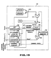
subtracter 81 at one input end (+). Here, FI = 1.5 MHz and ε = 0.1875 MHz. The value of Δ fOSC* set at the Δ fOSC*memory 77 then is fed to thesubtracter 81 at the other input end (-). The above mentioned spurious lead-indetector 78 controls the switchingcircuit 80 to be switched to the a side or b side when the AFT is led in and judges the output of thesubtracter 81 to be positive or negative so that, in case the switchingcircuit 80 is positive when on the a side and is negative when on the b side, the AFT will be considered to be led into the spurious I and this will be transmitted to the controllingcircuit 71. When the AFT is led into the spurious I, the controllingcircuit 71 will reset the Δ fOSC*memory 77 to make the fOSC* output fOSC (EXPE). At this time, the controllingcircuit 71 will judge this channel to be of no signal so that, at the time of an up/down channel selection, that channel will not be selected but the next channel will be selected or, at the time of a direct channel selection, the picture will be made, for example, blue (called a blue back) and the sound will be muted. - In Fig. 18, by detecting that the AFT is led into the spurious I, the desired channel is judged to have no signal but, in Fig. 19, by detecting that it is not led into the vicinity of the video carrier P, the desired channel is judged to have no signal.
- In Fig. 19, on the basis of an input channel switching signal, the controlling
circuit 91 delivers frequency data fOSC (EXPE) corresponding to the desired channel to anadder 93 at one input end from an fOSC (EXPE)memory 92. On the other hand, an AFT voltage (divalent output) VAFT from anAFT detector 9 is input into a P carrier lead-indetector 94 and is used to switch aswitching circuit 95. When the AFT is led in, the P carrier lead-indetector 94 will switch theswitching circuit 95 so as to feed data FP from a data memory FP to a Δ fOSC*memory 96. The data FP are about +0.2 MHz (See Figs. 13 and 17). When the AFT is led in, the Δ fOSC*memory 96 will receive a loading order through an OR-gate 97 from the P carrier lead-indetector 94 and will be loaded with the data FP. The output of the Δ fOSC*memory 96 is fed to the above mentionedadder 93 at the other input end and the value combined with the frequency data fOSC (EXPE) by theadder 93 is made the value of fOSC*. That is to say,
fOSC* = fOSC (EXPE) + Δ fOSC*
Δ fOSC* = FP ≃ 0.2 MHz. - In the P carrier lead-in
detector 94, after the above mentioned fOSC* is delivered through aconverter 98, after a predetermined time, the AFT voltage VAFT is measured and, when it is 0V, that is, "0" in FP as in Fig. 13, a video carrier P will be recongized to be present and the control will be transferred to anAFT controller 99. At this time, theswitch circuit 95 is switched to the a side. By the way, theconverter 98 is to convert digital data fOSC* to an analogue voltage value V2 (fOSC*). - When VAFT measured by the P carrier lead-in
detector 94 is 5V, that is, "1", the video carrier P of the desired channel will be judged to be absent and this will be transmitted to the controllingcircuit 91. In the controllingcircuit 91, the Δ fOSC*memory 96 is reset and the fOSC* output is made fOSC (EXPE). Also, at this time, the controllingcircuit 71 will operate the same as in the case of Fig. 18 and, at the time of an up/down channel selection, that channel will not be selected but the next channel will be selected or, at the time of a direct channel selection, the picture will be made, for example, blue (called a blue back) and the sound will be muted. - By the way, after the control is transferred to the
AFT controller 99, theAFT detector 9 will output an AFT voltage VAFT corresponding to V2 (fOSC*) and theAFT controller 99 will operate an AFT loop to search f02. That is to say, the AFT voltage (divalent output) from theAFT detector 9 will be input into theAFT controller 99 and will be used to switch aswitching circuit 100. By theAFT controller 99, theswitch circuit 100 is switched to the data memory nF STEP side in order to increase the frequency at a fixed step F STEP when the VAFT is "1" but to the data memory -nF STEP side in order to decrease the frequency at a fixed step F STEP when the VAFT is "0". The output from theswitch circuit 100 is fed to anadder 101 at one input end. The value of Δ fOSC* set then at the Δ fOSC*memory 96 is fed to theadder 101 at the other input end. The output of theadder 93 is output as V2 (fOSC*) through theconverter 98. TheAFT detector 9 outputs an AFT voltage VAFT corresponding to V2 (fOSC*). - As described above, according to the formation in Fig. 11 and the formation of the operation circuit in Fig. 18 or 19, in case there is no broadcast signal in a desired channel but there are broadcast signals in the upper and lower adjacent channels, the mis-operation of selecting channels by the obstruction by mixed signals (generated particularly in a strong electric field region) can be prevented. Therefore, the present invention is useful for automatically selecting channels by detecting present signals and for making a black picture when there is no signal.
- Reference signs in the claims are intended for better understanding and shall not limit the scope.
Claims (9)
characterized by being provided in said controlling means(5,6) with a means(65) for memorizing the information as to whether it is inhibited or permitted to select respective channels at the time of a channel-up or channel-down channel selection and memorizing the common channel selection inhibiting information for a plurality of channels not allowed to exist simultaneously.
characterized by comprising:
a size judging means(7,8) for judging the sizes of the above mentioned input high frequency signal frequency at a channel selecting time and the tuned frequency corresponding to the above mentioned local oscillation signal frequency at a search starting time;
as provided in said controlling means(5,6), a means(65) for memorizing the information as to whether it is inhibited or permitted to select respective channels at the time of a channel-up or channel-down channel selection and memorizing the common channel selection inhibiting information for a plurality of channels not allowed to exist simultaneously;
as provided in said controlling means(5,6), a means(61) for controlling by a negative feedback the above mentioned tuned frequency to lower the above mentioned tuned frequency when a result of judging that the above mentioned tuned frequency at the search starting time is larger than the above mentioned input high frequency signal frequency is obtained from the above mentioned size judging means(7,8) but to elevate the above mentioned tuned frequency when a result of judging that it is smaller on the contrary is provided and the channel selection is controlled to proceed toward the input high frequency signal frequency from the search starting time in selecting channels.
characterized by comprising:
an AFT detecting means(9) whereby, when the local oscillation frequency of this tuner(2) is swept in a predetermined direction, the difference from the prescribed frequency of the above mentioned intermediate frequency signal frequency will be output as an AFT voltage;
as provided in said controlling means(5,6), a means(65) for memorizing the information as to whether it is inhibited or permitted to select respective channels at the time of a channel-up or channel-down channel selection and memorizing the common channel selection inhibiting information for a plurality of channels not allowed to exist simultaneously; and
as provided in said controlling means(5,6), a means(61) wherein the frequency differences between a video carrier and a sound carrier of a lower adjacent channel and between the video carrier and a color sub-carrier are utilized to judge whether the AFT has been led into the above mentioned sound carrier or color sub-carrier and to detect the lead into the video carrier.
characterized by comprising:
an AFT detecting means(9) whereby, when the local oscillation frequency of this tuner(2) is swept in a predetermined direction, the difference from the prescribed frequency of the above mentioned intermediate frequency signal frequency will be output as an AFT voltage;
as provided in said controlling means(5,6), a means(65) for memorizing the information as to whether it is inhibited or permitted to select respective channels at the time of a channel-up or channel-down channel selection and memorizing the common channel selection inhibiting information for a plurality of channels not allowed to exist simultaneously; and
as provided in said controlling means(5,6), a means(61) wherein the difference between the above mentioned data corresponding to the local oscillation frequencies and the local oscillation frequency data corresponding to the video carrier of a desired channel is utilized to judge whether the AFT has been led in a specific frequency or not and to detect that there is no signal in the desired channel.
an operation processing part(6) wherein, on the basis of a channel-up or channel-down channel selecting operation, data corresponding to local oscillation frequencies of the respective channels are generated, a means(65) for memorizing the information as to whether it is inhibited or permitted to select respective channels at the time of a channel-up or channel-down channel selection is provided and the common channel selection inhibiting information for a plurality of channels not allowed to exist simultaneously is memorized; and
a PLL part(5) wherein a tuning voltage is prepared by using the data corresponding to the local oscillation frequencies from this operation processing part(6) and the local oscillation frequency of said tuner(2) is controlled to coincide with the data corresponding to the local oscillation frequencies.
an operation processing part(6) wherein, on the basis of a channel-up or channel-down channel selecting selecting operation, data corresponding to local oscillation frequencies of the respective channels are generated, a means(65) for memorizing the information as to whether it is inhibited or permitted to select respective channels at the time of a channel-up or channel-down channel selection is provided and the common channel selection inhibiting information for a plurality of channels not allowed to exist simultaneously is memorized, on the other hand, a means(61) for controlling by a negative feedback the above mentioned tuned frequency to lower the above mentioned tuned frequency when a result of judging that the above mentioned tuned frequency at the search starting time is larger than the above mentioned input high frequency signal frequency is obtained from the above mentioned size judging means(7,8) but to elevate the above mentioned tuned frequency when a result of judging that it is smaller on the contrary is provided and the channel selection is controlled to proceed toward the input high frequency signal frequency from the search starting time in selecting channels; and
a PLL part(5) wherein a tuning voltage is prepared by using the data corresponding to the local oscillation frequencies from this operation processing part(6) and the local oscillation frequency of said tuner(2) is controlled to coincide with the data corresponding to the local oscillation frequencies.
an operation processing part(6) wherein, on the basis of a channel-up or channel-down channel selecting operation, data corresponding to local oscillation frequencies of the respective channels are output, on the other hand, said data corresponding to the local oscillation frequencies are controlled with the AFT voltage from the above mentioned AFT detecting means(9), a means(65) for memorizing the information as to whether it is inhibited or permitted to select respective channels at the time of a channel-up or channel-down channel selection is provided, the common channel selection inhibiting information for a plurality of channels not allowed to exist simultaneously is memorized, on the other hand, a means(61) wherein the frequency differences between a video carrier and a sound carrier of a lower adjacent channel and between the video carrier and a color sub-carrier are utilized to judge whether the AFT has been led into the above mentioned sound carrier or color sub-carrier and to detect the lead into the video carrier is provided and, in case the AFT has been led into the above mentioned sound carrier or color sub-carrier, the video carrier will be searched again and the channel selection is controlled to find a tuning point of the video carrier; and
a PLL part(5) wherein a tuning voltage is prepared by using the data corresponding to the local oscillation frequencies from this operation processing part(6) and the local oscillation frequency of said tuner(2) is controlled to coincide with the data corresponding to the local oscillation frequencies.
an operation processing part(6) wherein, on the basis of a channel-up or channel-down channel selecting operation, data corresponding to local oscillation frequencies of the respective channels are output, on the other hand, said data corresponding to the local oscillation frequencies are controlled with the AFT voltage from the above mentioned AFT detecting means(9), a means(65) for memorizing the information as to whether it is inhibited or permitted to select respective channels at the time of a channel-up or channel-down channel selection is provided, the common channel selection inhibiting information for a plurality of channels not allowed to exist simultaneously is memorized, on the other hand, a means(61) wherein the difference between the above mentioned data corresponding to the local oscillation frequencies and the local oscillation frequency data corresponding to the video carrier of a desired channel is utilized to judge whether the AFT has been led in a specific frequency or not and to detect that there is no signal in the desired channel is provided and the channel selection is controlled on the basis of the result of this non-signal detection; and
a PLL part(5) wherein a tuning voltage is prepared by using the data corresponding to the local oscillation frequencies from this operation processing part(6) and the local oscillation frequency of said tuner(2) is controlled to coincide with the data corresponding to the local oscillation frequencies.
a first position memory(62) memorizing a channel corresponding to a first position;
a last position memory(63) memorizing a channel corresponding to a last position;
a channel number memory(64) memorizing channel number data corresponding to a position number;
a skip flag memory(65) memorizing the information as to whether each channel is to be skipped or not at the up/down channel selecting time;
a position number memory(67) memorizing a position number;
a stop position memory(66) memorizing a position up by 1 from the present position at the up/down channel selection starting time point and used to stop a loop continuing to refer to skip flags when the skip flags stand in all positions;
a data memory(fOSC* memory) corresponding to local oscillation frequencies memorizing data corresponding to local oscillation frequencies corresponding to channel numbers; and
an operation circuit(61) wherein, when a channel-up or channel-down key input is received, with reference to the above mentined skip flag memory(65), a channel to be selected is judged without being skipped, the judged selected channel is memorized in the above mentioned position number memory(67), data corresponding to this position are read out of the above mentioned channel number memory(64) and data corresponding to local oscillation frequencies corresponding to that channel number are prepared with reference to the above mentioned data memory(fOSC* memory) corresponding to local oscillation frequencies and are output to the above mentioned PLL part(5).
Applications Claiming Priority (2)
| Application Number | Priority Date | Filing Date | Title |
|---|---|---|---|
| JP1112894A JP2772032B2 (en) | 1989-05-01 | 1989-05-01 | Tuning device |
| JP112894/89 | 1989-05-01 |
Publications (3)
| Publication Number | Publication Date |
|---|---|
| EP0396103A2 true EP0396103A2 (en) | 1990-11-07 |
| EP0396103A3 EP0396103A3 (en) | 1991-06-12 |
| EP0396103B1 EP0396103B1 (en) | 1996-04-03 |
Family
ID=14598170
Family Applications (1)
| Application Number | Title | Priority Date | Filing Date |
|---|---|---|---|
| EP90108272A Expired - Lifetime EP0396103B1 (en) | 1989-05-01 | 1990-04-30 | Channel selecting apparatus |
Country Status (4)
| Country | Link |
|---|---|
| EP (1) | EP0396103B1 (en) |
| JP (1) | JP2772032B2 (en) |
| KR (1) | KR950003144B1 (en) |
| DE (2) | DE396103T1 (en) |
Cited By (3)
| Publication number | Priority date | Publication date | Assignee | Title |
|---|---|---|---|---|
| WO1996023354A1 (en) * | 1995-01-23 | 1996-08-01 | Rca Thomson Licensing Corporation | Wide frequency spectrum television tuner with single local oscillator |
| WO1996037980A1 (en) * | 1995-05-26 | 1996-11-28 | Silvio Della Mattia | Radio that receives the audio from television programs |
| EP1538831A1 (en) * | 2003-12-01 | 2005-06-08 | ORION ELECTRIC CO., Ltd. | Channel selecting unit |
Families Citing this family (1)
| Publication number | Priority date | Publication date | Assignee | Title |
|---|---|---|---|---|
| JPH04105722U (en) * | 1991-02-20 | 1992-09-11 | 三洋電機株式会社 | Preset channel selection device |
Citations (3)
| Publication number | Priority date | Publication date | Assignee | Title |
|---|---|---|---|---|
| US4375651A (en) * | 1981-07-27 | 1983-03-01 | Zenith Radio Corporation | Selective video reception control system |
| US4510623A (en) * | 1982-07-23 | 1985-04-09 | General Electric Company | Television channel lockout |
| JPS6336608A (en) * | 1986-07-31 | 1988-02-17 | Sony Corp | Television receiver |
-
1989
- 1989-05-01 JP JP1112894A patent/JP2772032B2/en not_active Expired - Lifetime
-
1990
- 1990-04-30 EP EP90108272A patent/EP0396103B1/en not_active Expired - Lifetime
- 1990-04-30 DE DE199090108272T patent/DE396103T1/en active Pending
- 1990-04-30 DE DE69026300T patent/DE69026300T2/en not_active Expired - Fee Related
- 1990-05-01 KR KR1019900006174A patent/KR950003144B1/en not_active IP Right Cessation
Patent Citations (3)
| Publication number | Priority date | Publication date | Assignee | Title |
|---|---|---|---|---|
| US4375651A (en) * | 1981-07-27 | 1983-03-01 | Zenith Radio Corporation | Selective video reception control system |
| US4510623A (en) * | 1982-07-23 | 1985-04-09 | General Electric Company | Television channel lockout |
| JPS6336608A (en) * | 1986-07-31 | 1988-02-17 | Sony Corp | Television receiver |
Non-Patent Citations (2)
| Title |
|---|
| & JP-A-63 036 608 (SONY CORP.) 17-02-1988 * |
| PATENT ABSTRACTS OF JAPAN, vol. 12, no. 246 (E-632), 12th July 1988; & JP-A-63 036 608 (SONY CORP.) 17-02-1988 * |
Cited By (4)
| Publication number | Priority date | Publication date | Assignee | Title |
|---|---|---|---|---|
| WO1996023354A1 (en) * | 1995-01-23 | 1996-08-01 | Rca Thomson Licensing Corporation | Wide frequency spectrum television tuner with single local oscillator |
| US5983088A (en) * | 1995-01-23 | 1999-11-09 | Rca Thomson Licensing Corporation | Wide frequency spectrum television tuner with single local oscillator |
| WO1996037980A1 (en) * | 1995-05-26 | 1996-11-28 | Silvio Della Mattia | Radio that receives the audio from television programs |
| EP1538831A1 (en) * | 2003-12-01 | 2005-06-08 | ORION ELECTRIC CO., Ltd. | Channel selecting unit |
Also Published As
| Publication number | Publication date |
|---|---|
| EP0396103A3 (en) | 1991-06-12 |
| JP2772032B2 (en) | 1998-07-02 |
| KR950003144B1 (en) | 1995-04-01 |
| DE396103T1 (en) | 1991-11-07 |
| EP0396103B1 (en) | 1996-04-03 |
| KR900019358A (en) | 1990-12-24 |
| JPH02291713A (en) | 1990-12-03 |
| DE69026300D1 (en) | 1996-05-09 |
| DE69026300T2 (en) | 1996-11-14 |
Similar Documents
| Publication | Publication Date | Title |
|---|---|---|
| US5193005A (en) | Channel selecting apparatus having a channel skip function | |
| US5313282A (en) | Device for controlling power supplied to a satellite broadcast receiver in a television | |
| EP0477753B1 (en) | A previous channel feature in a television receiver having multiple RF inputs | |
| KR960001540B1 (en) | Television receiver | |
| US5034819A (en) | Channel selecting apparatus and method used in a television receiving apparatus and capable of memorizing channel data | |
| KR100202340B1 (en) | Data entry apparatus | |
| KR100406985B1 (en) | Television displaying a searched channel during auto search, and a method for displaying searched channel of the same | |
| JPH0467370B2 (en) | ||
| JPH0543208B2 (en) | ||
| US6400422B1 (en) | Television receiver | |
| EP0396103A2 (en) | Channel selecting apparatus | |
| EP1662781A1 (en) | A method of tuning | |
| KR0176719B1 (en) | Stability detection method and apparatus for tuning system | |
| JP3969828B2 (en) | RF converter output channel automatic setting device, video tuner device and VTR for television signal receiver | |
| KR930010180B1 (en) | Apparatus and method for automatic tv channels selection | |
| KR100688882B1 (en) | A method for shortening scan time in video display apparatus for use in both analog and digital broadcasting | |
| JP2570284B2 (en) | TV receiver | |
| JP3339389B2 (en) | Video equipment | |
| KR960006828B1 (en) | Auto channel search apparatus & method | |
| JP3379696B2 (en) | Television receiver | |
| KR0164707B1 (en) | Autoamtic channeling method and the device of vcr | |
| KR20030002531A (en) | Channel search method and an apparatus of a television | |
| KR910003472Y1 (en) | Automatic station selecting circuit | |
| JP3954961B2 (en) | Automatic channel selection apparatus and preset method | |
| KR19980058810A (en) | Channel tuning method of video equipment |
Legal Events
| Date | Code | Title | Description |
|---|---|---|---|
| PUAI | Public reference made under article 153(3) epc to a published international application that has entered the european phase |
Free format text: ORIGINAL CODE: 0009012 |
|
| 17P | Request for examination filed |
Effective date: 19900430 |
|
| AK | Designated contracting states |
Kind code of ref document: A2 Designated state(s): DE FR GB |
|
| PUAL | Search report despatched |
Free format text: ORIGINAL CODE: 0009013 |
|
| AK | Designated contracting states |
Kind code of ref document: A3 Designated state(s): DE FR GB |
|
| EL | Fr: translation of claims filed | ||
| DET | De: translation of patent claims | ||
| 17Q | First examination report despatched |
Effective date: 19940127 |
|
| GRAA | (expected) grant |
Free format text: ORIGINAL CODE: 0009210 |
|
| AK | Designated contracting states |
Kind code of ref document: B1 Designated state(s): DE FR GB |
|
| REF | Corresponds to: |
Ref document number: 69026300 Country of ref document: DE Date of ref document: 19960509 |
|
| ET | Fr: translation filed | ||
| GRAH | Despatch of communication of intention to grant a patent |
Free format text: ORIGINAL CODE: EPIDOS IGRA |
|
| PLBE | No opposition filed within time limit |
Free format text: ORIGINAL CODE: 0009261 |
|
| STAA | Information on the status of an ep patent application or granted ep patent |
Free format text: STATUS: NO OPPOSITION FILED WITHIN TIME LIMIT |
|
| 26N | No opposition filed | ||
| PGFP | Annual fee paid to national office [announced via postgrant information from national office to epo] |
Ref country code: FR Payment date: 19970409 Year of fee payment: 8 |
|
| PGFP | Annual fee paid to national office [announced via postgrant information from national office to epo] |
Ref country code: GB Payment date: 19970421 Year of fee payment: 8 |
|
| PGFP | Annual fee paid to national office [announced via postgrant information from national office to epo] |
Ref country code: DE Payment date: 19970509 Year of fee payment: 8 |
|
| PG25 | Lapsed in a contracting state [announced via postgrant information from national office to epo] |
Ref country code: GB Free format text: LAPSE BECAUSE OF NON-PAYMENT OF DUE FEES Effective date: 19980430 Ref country code: FR Free format text: THE PATENT HAS BEEN ANNULLED BY A DECISION OF A NATIONAL AUTHORITY Effective date: 19980430 |
|
| GBPC | Gb: european patent ceased through non-payment of renewal fee |
Effective date: 19980430 |
|
| PG25 | Lapsed in a contracting state [announced via postgrant information from national office to epo] |
Ref country code: DE Free format text: LAPSE BECAUSE OF NON-PAYMENT OF DUE FEES Effective date: 19990202 |
|
| REG | Reference to a national code |
Ref country code: FR Ref legal event code: ST |