EP0380046A2 - Method for testing counters, in particular electricity, water or gas meters, and device for carrying out this method - Google Patents
Method for testing counters, in particular electricity, water or gas meters, and device for carrying out this method Download PDFInfo
- Publication number
- EP0380046A2 EP0380046A2 EP90101281A EP90101281A EP0380046A2 EP 0380046 A2 EP0380046 A2 EP 0380046A2 EP 90101281 A EP90101281 A EP 90101281A EP 90101281 A EP90101281 A EP 90101281A EP 0380046 A2 EP0380046 A2 EP 0380046A2
- Authority
- EP
- European Patent Office
- Prior art keywords
- rotating element
- light beam
- light
- incident light
- reflected
- Prior art date
- Legal status (The legal status is an assumption and is not a legal conclusion. Google has not performed a legal analysis and makes no representation as to the accuracy of the status listed.)
- Granted
Links
Images

Classifications
-
- G—PHYSICS
- G06—COMPUTING; CALCULATING OR COUNTING
- G06M—COUNTING MECHANISMS; COUNTING OF OBJECTS NOT OTHERWISE PROVIDED FOR
- G06M1/00—Design features of general application
- G06M1/27—Design features of general application for representing the result of count in the form of electric signals, e.g. by sensing markings on the counter drum
- G06M1/272—Design features of general application for representing the result of count in the form of electric signals, e.g. by sensing markings on the counter drum using photoelectric means
-
- G—PHYSICS
- G01—MEASURING; TESTING
- G01R—MEASURING ELECTRIC VARIABLES; MEASURING MAGNETIC VARIABLES
- G01R35/00—Testing or calibrating of apparatus covered by the other groups of this subclass
- G01R35/04—Testing or calibrating of apparatus covered by the other groups of this subclass of instruments for measuring time integral of power or current
-
- G—PHYSICS
- G06—COMPUTING; CALCULATING OR COUNTING
- G06M—COUNTING MECHANISMS; COUNTING OF OBJECTS NOT OTHERWISE PROVIDED FOR
- G06M3/00—Counters with additional facilities
- G06M3/12—Counters with additional facilities for preventing incorrect actuation, e.g. for preventing falsification
Landscapes
- Physics & Mathematics (AREA)
- General Physics & Mathematics (AREA)
- Engineering & Computer Science (AREA)
- Theoretical Computer Science (AREA)
- Investigating Or Analysing Materials By Optical Means (AREA)
- Production Of Liquid Hydrocarbon Mixture For Refining Petroleum (AREA)
- Testing Relating To Insulation (AREA)
- Measuring Volume Flow (AREA)
Abstract
Description
Die Erfindung betrifft ein Verfahren zur Prüfung von Zählern, insbesondere zur Prüfung von Elektrizitäts-, Gas- und Wasserzählern, mit den Merkmalen aus dem Oberbegriff des Patentanspruchs 1.The invention relates to a method for testing meters, in particular for testing electricity, gas and water meters, with the features from the preamble of
Die von Energie- und Wasserversorgungsunternehmen verwendeten Zähler müssen in bestimmten Zeitabständen auf ihre Genauigkeit geprüft und beglaubigt werden. Ein bekanntes Verfahren zu dieser Prüfung besteht darin, daß der Zähler in einer Prüfvorrichtung mit einem Gebrauchsnormal verglichen wird, wobei beide Zähler beispielsweise mit der gleichen Wassermenge beschickt werden. Bei diesem Verfahren ist zur Erzielung einer hohen Genauigkeit einer große Wassermenge erforderlich. Dies hat lange Prüfzeiten zur Folge.The meters used by energy and water supply companies must be checked and certified for their accuracy at certain intervals. A known method for this test consists in comparing the meter in a test device with a usage standard, both meters being charged with the same amount of water, for example. This method requires a large amount of water to achieve high accuracy. This results in long test times.
Es ist auch bereits ein Verfahren mit den Merkmalen aus dem Oberbegriff des Patentanspruchs 1 bekannt. Dieses Verfahren beruht beispielsweise bei einem Wasserzähler auf der Voraussetzung, daß innerhalb des Gehäuses ein rotierendes Element angeordnet ist, das bei Betätigung des Meßwerks durch das zu meßende Medium in Rotation versetzt wird. Das rotierende Element muß dabei so angeordnet sein, daß es von einem Lichtbündel getroffen werden kann, das von einer außerhalb des Gehäuses angeordneten Lichtquelle ausgeht. Ein Teil des auftreffenden Lichtes wird reflektiert und das reflektierte Lichtbün del wird über einen Fotoempfänger einer Auswerteeinrichtung zugeführt. Das rotierende Element besitzt,z.B.längs seines Umfangs. Randausnehmungen gleicher Breite, die in gleichmäßigen Abständen angeordnet sind. Dies hat zur Folge, daß die Lichtintensität im reflektierten Lichtbündel eine ausgeprägte Periodizität aufweist. Die in der Auswerteeinrichtung aufgrund dieser Periodizität entstehenden Impulse werden gezählt, und aus der Anzahl der gezählten Impulse kann aufgrund bekannter, auf der besonderen jeweiligen Konstruktion des Zählers beruhender Zusammenhänge die durchgeflossene Wassermenge und damit der Fehler des zu prüfenden Zählers leicht errechnet werden.A method with the features from the preamble of
Ein entscheidender Nachteil dieses bekannten Verfahrens und der vorrichtungen, mit denen es ausgeübt werden kann, besteht darin, daß als Lichtquelle eine normale Glühlampe eingesetzt wird. Der Glühfaden einer Glühlampe hat eine Länge von mehreren Millimetern. Eine starke Fokussierung des vom Glühfaden ausgesandten, breitgefächerten Lichtbündels ist außerordentlich schwierig und nur mit teuren Optiken erreichbar. Eine solche Fokussierung ist aber notwendig, da, wenn der Durchmesser des auftreffenden Lichtbündels die Breite der Ausnehmungen oder dgl. wesentlich übersteigt, keine eindeutigen Reflexionsbedingungen entstehen können. Bei ungenügender Fokussierungsmöglichkeit müssen beispielsweise die Randausnehmungen des rotierenden Elementes relativ groß gewählt werden, was eine Verringerung des Auflösevermögens der Prüfvorrichtung und eine Prüfzeitverlangerung zur Folge hat.A decisive disadvantage of this known method and the devices with which it can be practiced is that a normal incandescent lamp is used as the light source. The filament of an incandescent lamp has a length of several millimeters. It is extremely difficult to focus the broad beam of light emitted by the filament extremely, and it can only be achieved with expensive optics. Such focusing is necessary, however, because if the diameter of the incident light beam significantly exceeds the width of the recesses or the like, no clear reflection conditions can arise. If the focusing option is insufficient, the edge recesses of the rotating element, for example, must be chosen to be relatively large, which results in a reduction in the resolving power of the test device and in an increase in the test time.
Ein weiterer Nachteil bei der Verwendung einer Glühlampe als Lichtquelle besteht beispielsweise bei einem als sogenannter Naßläufer arbeitenden Wasserzähler darin, daß sowohl das ausgesandte als auch des reflektierte Lichtbündel die Medien Luft, Glas und Wasser durchdringt, was wegen der verschiedenen Brechungsindizes und der großen Bandbreite des verwendeten Lichts eine starke Streuung ergibt. Ebenso verlagert sich beispielsweise der Brennpunkt eines solchen Lichtbündels, wenn bewegliche Luftblaseneinschlüsse im Wasser vorhanden sind. Diese Faktoren tragen dazu bei, daß das reflektierte Lichtbündel eine sehr geringe Intensität besitzt. Daher müssen bei der Auswertung elektronische Verstärker mit hoher Verstärkung eingesetzt werden. Hierdurch wird aber die Auswerteeinrichtung sehr empfindlich gegen Störimpulse und Fremdlichteinflüsse.Another disadvantage of using an incandescent lamp as a light source, for example in the case of a water meter operating as a so-called wet-running device, is that both the emitted and the reflected one Beams of light penetrate the media air, glass and water, which results in a strong scatter due to the different refractive indices and the wide range of light used. Likewise, for example, the focal point of such a light beam shifts when there are movable air bubble inclusions in the water. These factors contribute to the fact that the reflected light beam has a very low intensity. Therefore, electronic amplifiers with high amplification must be used in the evaluation. This makes the evaluation device very sensitive to interference pulses and external light influences.
Die oben angegebenen Nachteile begrenzen die Anwendbarkeit des bekannten Verfahrens in starkem Maße. Im Bereich der Prüfung von Kaltwasserdurchflußmeßgeräten ist dieses Verfahren nur bei geringer Meßauflösung möglich. Höhere Meßauflösungen werden bei Prüfvorrichtungen herkömmlicher Art nur dann erreicht, wenn sie speziell an einen bestimmten Zählertyp angepaßt sind.The above-mentioned disadvantages severely limit the applicability of the known method. In the field of testing cold water flowmeters, this method is only possible with low measurement resolution. Higher measurement resolutions can only be achieved with test devices of conventional type if they are specially adapted to a certain type of meter.
Der Erfindung liegt die Aufgabe zugrunde, ein Verfahren mit den Merkmalen aus dem Oberbegriff des Patentanspruchs 1 sowie eine Vorrichtung zur Durchführung dieses Verfahrens zu schaffen, das ohne aufwendige Justiervorgänge mit geringem Zeitaufwand durchgeführt werden kann und zu Ergebnissen mit einer wesentlich höheren Genauigkeit bei nur geringem Zeitaufwand führt. Fehlerquellen sollen vermieden oder doch so weitgehend verringert werden, daß sie auf das Prüfergebnis keine ins Gewicht fallende Auswirkung haben.The invention has for its object to provide a method with the features of the preamble of
Die Lösung dieser Aufgabe geschieht erfindungsgemäß mit den Merkmalen aus dem kennzeichnenden Teil des Patentanspruchs 1. Das erfindungsgemäße Verfahren kann gemäß der weiteren Erfindung mit einer Vorrichtung ausgeübt werden, welche die in Patentanspruch 2 angegebenen Merkmale aufweist. Vorteilhafte Weiterbildungen der erfindungsgemäßen Vorrichtung sind in den Ansprüchen 3 bis 9 beschrieben.This object is achieved according to the invention with the features from the characterizing part of
Ein wesentlicher Vorteil der Verwendung von kohärentem Licht gemäß der Erfindung besteht darin, daß ohne aufwendige Fokussierungsmaßnahmen parallele Lichtbündel mit kleinem Bündeldurchmesser und hoher Energiedichte erzeugt werden können, wobei aufgrund des monochromen Charakters dieses Lichtes eine Streuung des Lichtes beim Durchtritt durch verschiedene Medien nicht stattfindet. Es läßt sich daher erreichen, daß die Energiedichte im reflektierten Lichtbündel nahezu die gleiche wie im ausgesandten Lichtbündel ist. Die in der Auswerteeinrichtung vorgesehenen Verstärker benötigen keinen so hohen Verstärkungsgrad und die Gefahr von Störimpulsen ist stark reduziert. Ein in der Empfangsvorrichtung vorgesehener Fotoempfänger kann der Wellenlänge des ausgesandten Lichtes angepaßt werden, wodurch Fremdlichteinflüsse stark unterdrückt werden. Die in der Prüfvorrichtung benötigten Optiken sind einfacher und preiswerter auszugestalten und es sind keine aufwendigen Fokussierungsmaßnahmen notwendig. Aufgrund des kleinen Bündeldurchmessers des ausgesandten Lichtbündels können beispielsweise bei einem als reflektierende Scheibe ausgebildeten rotierenden Element die Durchbrechungen, Randausnehmungen oder dgl. eine sehr geringe Breite aufweisen, so daß bei einem vorgegebenen Gesamtdurchmesser des rotierenden Elementes auf dem Umfang eine große Anzahl von Ausnehmungen oder dgl. angeordnet werden kann, was zu einer Erhöhung des Auflösevermögens und damit der Genauigkeit des Verfahrens führt.A major advantage of the use of coherent light according to the invention is that parallel light bundles with a small bundle diameter and high energy density can be produced without complex focusing measures, and because of the monochrome character of this light, the light does not scatter when it passes through different media. It can therefore be achieved that the energy density in the reflected light bundle is almost the same as in the emitted light bundle. The amplifiers provided in the evaluation device do not require such a high degree of amplification and the risk of interference pulses is greatly reduced. A photo receiver provided in the receiving device can be adapted to the wavelength of the emitted light, as a result of which external light influences are strongly suppressed. The optics required in the test device are simpler and cheaper to design and no complex focusing measures are necessary. Due to the small bundle diameter of the emitted light bundle, the openings, edge recesses or the like can have a very small width, for example in the case of a rotating element designed as a reflecting disk, so that a large number of recesses or the like can be found on the circumference for a predetermined total diameter of the rotating element. can be arranged, which leads to an increase in the resolving power and thus the accuracy of the method.
Ein weiterer Vorteil besteht darin, daß Verfahren und Vorrichtung nach der Erfindung universell anwendbar sind derart, daß für unterschiedliche Zählerarten und- typen derselbe Abtastkopf benutzt werden kann.Another advantage is that the method and device according to the invention are universally applicable in such a way that the same scanning head can be used for different types and types of counters.
Bei einer vorteilhaften in Anspruch 7 beschriebenen Ausführungsform der erfindungsgemäßen Vorrichtung wird der Durchmesser des einfallenden Lichtbündels durch eine einem Strahlteiler vor und/oder nachgeschaltete optische Einrichtung, beispielsweise ein teleskopisches System, weiter verengt. Ist diese Einrichtung so angeordnet, daß sie auch vom reflektierten Lichtbündel durchlaufen wird, so erweitert sich dessen Durchmesser wieder vor dem Auftreffen auf den Fotoempfänger. Dies hat den Vorteil, daß auch bei Schwankungen des Reflexionswinkels, welche durch mechanische Ungenauigkeiten des rotierenden Elementes hervorgerufen werden, der Fotoempfänger mindestens von einem Teil des reflektierten Lichtbündels getroffen wird.In an advantageous embodiment of the device according to the invention described in claim 7, the diameter of the incident light bundle is further narrowed by an optical device, for example a telescopic system, which is arranged upstream and / or downstream of a beam splitter. If this device is arranged in such a way that the reflected light bundle passes through it, its diameter expands again before it hits the photo receiver. This has the advantage that even with fluctuations in the angle of reflection, which are caused by mechanical inaccuracies of the rotating element, the photo receiver is hit by at least part of the reflected light beam.
Das zur Messung verwendete Licht kann im sichtbaren Bereich des Spektrums liegen, was die Justierung der Vorrichtung erleichtert. Selbstverständlich kann aber auch mit dem menschlichen Auge nicht sichtbaren Licht, beispielsweise im Infrarotbereich, gearbeitet, werden.The light used for the measurement can be in the visible range of the spectrum, which facilitates the adjustment of the device. Of course, it is also possible to work with light that is not visible to the human eye, for example in the infrared range.
Besonders vorteilhaft ist eine Ausgestaltung der erfindungsgemäßen Vorrichtung, bei der als Lichtquelle eine an sich bekannte Laser-Halbleiterdiode dient, die einen geringen Platzbedarf besitzt, mechanisch unempfindlich ist und mit niedriger Spannung betrieben werden kann. Das erfindungsgemäße Verfahren und die erfindungsgemäße Vorrichtung können an allen Zählern mit mechanischen Zählwerken eingesetzt werden, die ein rotierendes Element aufweisen, dessen Bewegung eine Funktion der Zählrate ist. Besonders vorteilhaft ist die Anwendung des erfindungsgemäßen Verfahrens und der erfindungsgemäßen Vorrichtung bei der Prüfung von Kaltwasserdurchflußmeßgeräten.An embodiment of the device according to the invention is particularly advantageous in which a laser semiconductor diode known per se is used as the light source, which requires little space, is mechanically insensitive and can be operated at low voltage. The method according to the invention and the device according to the invention can be used on all counters with mechanical counters which have a rotating element, the movement of which is a function of the counting rate. The application of the The inventive method and the device according to the invention in the testing of cold water flow meters.
Im folgenden wird anhand der beigefügten Zeichnungen ein Ausführungsbeispiel für eine Vorrichtung zur Durchführung des erfindungsgemäßen Verfahrens näher erläutert.An exemplary embodiment of a device for carrying out the method according to the invention is explained in more detail below with reference to the accompanying drawings.
In den Zeichnungen zeigen:
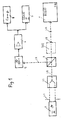
- Fig. 1 in einem Blockschaltbild eine Vorrichtung zur Prüfung eines Wasserzählers;
- Fig. 2 im Längsschnitt den zu prüfenden Wasserzähler;
- Fig. 3 den Wasserzähler nach Fig. 1 in Aufsicht;
- Fig. 4 in abgewickelter Darstellung das Anzeigesystem des Wasserzählers nach Fig. 2 und 3.
- Figure 1 is a block diagram of a device for testing a water meter.
- 2 shows a longitudinal section of the water meter to be tested;
- Fig. 3 the water meter of Figure 1 in supervision.
- 4 in a developed representation the display system of the water meter according to FIGS. 2 and 3.
Es soll zunächst anhand der Fig. 2 bis 4 der Aufbau und die Funktionsweise eines Wasserzählers herkömmlicher Bauart näher erläutert werden.The construction and operation of a water meter of conventional design will first be explained in more detail with reference to FIGS. 2 to 4.
Der Wasserzähler 1 besitzt ein Gehäuse 9 mit einem Zufluß- und einem Abflußstutzen zum Einbau in eine Wasserleitung. In einen Ansatz 9.1 an der Oberseite des Gehäuses 9 ist ein Durchflußmeßwerk eingebaut mit einem in einem Rahmen 16 um eine zentrale Achse drehbaren Flügelrad 17, das durch ein Sieb 18 hindurch vom durchfließenden Wasser angeströmt wird. Oberhalb des Flügelrades 17 ist innerhalb eines Gestells 15 des Meß- und Anzeigewerk angeordnet, das ein nicht näher erläutertes und an sich bekanntes, in Fig. 4 in Abwicklung dargestelltes Untersetzungsgetriebe aufweist, über welches die Bewegung des Flügelrades 17 zunächst auf ein Sternrad 19 übertragen wird. Das Sternrad 19 weist Randaus nehmungen 19.1 auf, die jeweils die gleiche Breite besitzen und in gleichen Abständen am Umfang angeordnet sind. Vom Sternrad 19 aus werden dann Zeiger 20, 21, 22 und 23 sowie ein Ziffernwark 24 angetrieben, mittels derer die Durchflußmenge in einzelnen Dekaden des gemessenen Wertes angezeigt wird.The
An der Oberseite ist der Ansatz 9.1 des Gehäuses 9 mit einem Glasfenster 10, das über Dichtungen 12 und 13 in einem Rahmenteil 11 sitzt, abgeschlossen. Ein um eine Achse 14.1 auf- und zuklappbarer Deckel 14 schützt das Glasfenster 10 vor Beschädigung.At the top, the neck 9.1 of the housing 9 is closed with a
Zur Prüfung des in den Fig. 2 bis 4 dargestellten Wasserzählers 1 dient eine Vorrichtung gemäß Fig. 1.A device according to FIG. 1 is used to test the
Von einer Lichtquelle 2, die kohärentes Licht aussendet und beispielsweise als Laser-Halbleiterdiode ausgebildet sein kann, geht ein Lichtbündel LE aus, dessen Durchmesser durch eine Blende 3.1 und gegebenenfalls weitere optische Einrichtungen 3.2, z.B. ein teleskopisches System, begrenzt wird. Das Lichtbündel LE durchsetzt einen Strahlteilerwürfel 4 und trifft schließlich durch das Glasfenster 10 des Wasserzählers 1 hindurch auf den Umfangsbereich des Sternrades 19. Der Durchmesser des auftreffenden Lichtbündels LE kann so gewählt sein, daß er nicht größer ist als die Breite einer der Ausnehmungen 19.1 im Sternrad 19. Das Sternrad 19 oder zumindest der zwischen den Ausnehmungen 19.1 liegende Bereich ist so ausgebildet, daß er das Licht der verwendeten Wellenlänge gut reflektiert, während die hinter bzw. unter dem Sternrad 19 liegenden Bauteile des Zählers nichtreflektierende Oberflächen besitzen. Das vom Sternrad 19 reflektierte Lichtbündel LR läuft zurück zum Strahltei lerwürfel 4, wird dort um 90° abgelenkt und trifft schließlich auf einen Fotoempfänger 5, dessen Empfangscharakteristik der Wellenlänge des ausgesendeten Lichtes angepaßt ist. Das vom Fotoempfänger erzeugte elektrische Signal wird einer Auswerteeinrichtung zugeführt, von der in Fig. 1 lediglich ein Verstärker 6, ein Impulszähler 7 und ein Computer 8 dargestellt ist. Selbstverständlich kann die Auswerteeinrichtung auch weitere Einrichtungen zur Analysierung des vom Fotoempfänger 5 abgegebenen Signals auf Periodizität aufweisen.A light bundle LE emerges from a
Aufgrund der Rotation des Sternrades 19 wird das ausgesandte Lichtbündel LE beim Auftreffen periodisch reflektiert oder durchgelassen. Die Intensität des reflektierten Lichtbündels LR besitzt daher eine ausgeprägte Periodizität, die in der Auswerteeinrichtung erkannt und ausgewertet wird. Die Impulse werden gezählt und im Rechner 8 kann sowohl die Durchflußmenge als auch die Genauigkeit des Zählers berechnet werden.Due to the rotation of the
Abweichend von der Darstellung in Fig. 1 kann die optische Einrichtung 3.2, wie gestrichelt angedeutet, zur Verengung des Lichtbündels LE auch dem Strahlteilerwürfel 4 nachgeschaltet sein, um sicherzustellen, daß bei Schwankungen des Reflexionswinkels, die durch mechanische Ungenauigkeiten des Sternrades 19 hervorgerufen werden, der Fotoempfänger 5 noch getroffen wird. Es ist auch möglich, bei der Vorrichtung nach Fig. 1 eine zweite optische Einrichtung 3.2 zwischen dem Strahlteilerwürfel 4 und dem Sternrad 19 des Wasserzählers 1 vorzusehen.1, the optical device 3.2, as indicated by dashed lines, can also be connected downstream of the
Claims (9)
Applications Claiming Priority (2)
| Application Number | Priority Date | Filing Date | Title |
|---|---|---|---|
| DE3901816A DE3901816A1 (en) | 1989-01-23 | 1989-01-23 | METHOD FOR TESTING COUNTERS, ESPECIALLY ELECTRICITY, GAS AND WATER METERS, AND DEVICE FOR IMPLEMENTING THE METHOD |
| DE3901816 | 1989-01-23 |
Publications (3)
| Publication Number | Publication Date |
|---|---|
| EP0380046A2 true EP0380046A2 (en) | 1990-08-01 |
| EP0380046A3 EP0380046A3 (en) | 1992-01-02 |
| EP0380046B1 EP0380046B1 (en) | 1996-01-17 |
Family
ID=6372573
Family Applications (1)
| Application Number | Title | Priority Date | Filing Date |
|---|---|---|---|
| EP90101281A Expired - Lifetime EP0380046B1 (en) | 1989-01-23 | 1990-01-23 | Method for testing counters, in particular electricity, water or gas meters, and device for carrying out this method |
Country Status (4)
| Country | Link |
|---|---|
| EP (1) | EP0380046B1 (en) |
| AT (1) | ATE133278T1 (en) |
| DE (2) | DE3901816A1 (en) |
| DK (1) | DK0380046T3 (en) |
Cited By (5)
| Publication number | Priority date | Publication date | Assignee | Title |
|---|---|---|---|---|
| EP1795868A2 (en) | 2005-12-07 | 2007-06-13 | EL-ME Metering Systems GmbH | Optoelectronic device for recording the rotation of a rotary element and method for evaluating the signals of such a device |
| DE202008007959U1 (en) | 2007-06-15 | 2008-10-16 | Oohlsee B.V. | Device for reading a consumption meter for electricity, gas and / or water |
| CN103645457A (en) * | 2013-12-20 | 2014-03-19 | 国家电网公司 | On-site inspection device for electric energy meter |
| CZ305952B6 (en) * | 2014-07-15 | 2016-05-18 | Vysoká Škola Báňská - Technická Univerzita Ostrava Fakulta Elektroniky A Informatiky, Katedra Kybernetiky A Biomedicínského Inženýrství | Tester and method of detecting error of consumer electric supply meter |
| CN112683371A (en) * | 2020-12-11 | 2021-04-20 | 浙江苍南仪表集团股份有限公司 | Signal detection method for gas turbine flowmeter verification |
Families Citing this family (5)
| Publication number | Priority date | Publication date | Assignee | Title |
|---|---|---|---|---|
| DE19527588C2 (en) * | 1995-07-28 | 1997-07-10 | Ind Technik Froeschl Gmbh | Procedure for checking counters with displays |
| DE19717128A1 (en) * | 1997-04-23 | 1998-10-29 | Imcon Ges Fuer Bildverarbeitun | Device and method for testing consumption meters, in particular house water meters and apartment water meters |
| DE10060198A1 (en) * | 2000-12-01 | 2002-06-13 | Abb Patent Gmbh | Measurement of volume flow rate, especially for a water meter with an impulse generator and sensor combination of simple design that yields improved signal resolution |
| CN102914727B (en) * | 2012-09-24 | 2015-07-22 | 中国电力科学研究院 | System and method for testing ultraviolet visible light coincidence deviation of ultraviolet detector |
| CN106447018B (en) * | 2016-10-21 | 2018-12-14 | 北京京东尚科信息技术有限公司 | Sort householder method and device, sorting system |
Citations (2)
| Publication number | Priority date | Publication date | Assignee | Title |
|---|---|---|---|---|
| EP0060937A1 (en) * | 1981-03-17 | 1982-09-29 | LGZ LANDIS & GYR ZUG AG | Arrangement for representing the result of count-on-drum counters in the form of electric signals |
| GB2155673A (en) * | 1984-02-09 | 1985-09-25 | Thorn Emi Dynatel Limited | Improvements in or relating to meters |
Family Cites Families (3)
| Publication number | Priority date | Publication date | Assignee | Title |
|---|---|---|---|---|
| DE1179017B (en) * | 1960-12-24 | 1964-10-01 | Bopp & Reuther Gmbh | Counter checking system |
| DE2726242C2 (en) * | 1977-06-10 | 1984-11-08 | Kienzle Apparate Gmbh, 7730 Villingen-Schwenningen | Rotation pulse generator |
| GB2171209B (en) * | 1985-02-20 | 1988-12-14 | Smith Meters Ltd | Test equipment |
-
1989
- 1989-01-23 DE DE3901816A patent/DE3901816A1/en not_active Withdrawn
-
1990
- 1990-01-23 DE DE59010059T patent/DE59010059D1/en not_active Expired - Fee Related
- 1990-01-23 EP EP90101281A patent/EP0380046B1/en not_active Expired - Lifetime
- 1990-01-23 DK DK90101281.5T patent/DK0380046T3/en active
- 1990-01-23 AT AT90101281T patent/ATE133278T1/en active
Patent Citations (2)
| Publication number | Priority date | Publication date | Assignee | Title |
|---|---|---|---|---|
| EP0060937A1 (en) * | 1981-03-17 | 1982-09-29 | LGZ LANDIS & GYR ZUG AG | Arrangement for representing the result of count-on-drum counters in the form of electric signals |
| GB2155673A (en) * | 1984-02-09 | 1985-09-25 | Thorn Emi Dynatel Limited | Improvements in or relating to meters |
Non-Patent Citations (1)
| Title |
|---|
| Jeff Hecht: The Laser Guidebook, 1986, New York, Seiten 3 und 4 * |
Cited By (7)
| Publication number | Priority date | Publication date | Assignee | Title |
|---|---|---|---|---|
| EP1795868A2 (en) | 2005-12-07 | 2007-06-13 | EL-ME Metering Systems GmbH | Optoelectronic device for recording the rotation of a rotary element and method for evaluating the signals of such a device |
| EP1795868A3 (en) * | 2005-12-07 | 2008-07-16 | EL-ME Metering Systems GmbH | Optoelectronic device for recording the rotation of a rotary element and method for evaluating the signals of such a device |
| DE202008007959U1 (en) | 2007-06-15 | 2008-10-16 | Oohlsee B.V. | Device for reading a consumption meter for electricity, gas and / or water |
| CN103645457A (en) * | 2013-12-20 | 2014-03-19 | 国家电网公司 | On-site inspection device for electric energy meter |
| CN103645457B (en) * | 2013-12-20 | 2016-06-01 | 国家电网公司 | A kind of on-site inspection device for electric energy meter |
| CZ305952B6 (en) * | 2014-07-15 | 2016-05-18 | Vysoká Škola Báňská - Technická Univerzita Ostrava Fakulta Elektroniky A Informatiky, Katedra Kybernetiky A Biomedicínského Inženýrství | Tester and method of detecting error of consumer electric supply meter |
| CN112683371A (en) * | 2020-12-11 | 2021-04-20 | 浙江苍南仪表集团股份有限公司 | Signal detection method for gas turbine flowmeter verification |
Also Published As
| Publication number | Publication date |
|---|---|
| EP0380046A3 (en) | 1992-01-02 |
| DE59010059D1 (en) | 1996-02-29 |
| DE3901816A1 (en) | 1990-07-26 |
| DK0380046T3 (en) | 1996-03-18 |
| EP0380046B1 (en) | 1996-01-17 |
| ATE133278T1 (en) | 1996-02-15 |
Similar Documents
| Publication | Publication Date | Title |
|---|---|---|
| DE69921009T2 (en) | Optical flow meter | |
| DE3832901C2 (en) | ||
| DE2325457A1 (en) | DEVICE FOR MEASURING THE DISTANCE OF SURFACES MADE OF TRANSPARENT MATERIAL | |
| EP3521810A1 (en) | Analyser for the determination of fine dust | |
| DE4219260C2 (en) | Photoelectric device with a test object | |
| DE3104320A1 (en) | "DEVICE AND METHOD FOR OPTICAL DISTANCE DETERMINATION" | |
| EP0380046B1 (en) | Method for testing counters, in particular electricity, water or gas meters, and device for carrying out this method | |
| DE3506328C2 (en) | Method for correcting coincidence errors in parameter data of particles obtained in a particle analysis arrangement, and device for carrying out the method | |
| EP0210263B1 (en) | Device for optical determination of low-order errors in shape | |
| DE19911654C1 (en) | Device for determining the speed and size of particles | |
| DE3347092C2 (en) | ||
| EP0048014A1 (en) | Apparatus for measuring the extinction coefficient of laser range-finders | |
| EP0467127A2 (en) | Method and device for optically detecting and evaluating scattered light signals | |
| DE2852614A1 (en) | OPTICAL MEASURING SYSTEM | |
| DE19723999A1 (en) | Device for measuring particle dimensions in fluids | |
| DE3315456C2 (en) | Device for determining particle sizes | |
| DE3629966C2 (en) | ||
| DE19626187C2 (en) | Method and arrangement for the detection of objects | |
| EP0600048A1 (en) | Process for measuring relative angles | |
| DE1218169B (en) | Device for checking the wall thickness of glass tubes | |
| DE2829736C2 (en) | Calibration device for recording the calibration curve of a photoelectric aerosol analyzer | |
| DE3028564A1 (en) | Automatic light refraction meter using deflection principle - for process control or chromatographic analysis | |
| DE2623653C3 (en) | Photometer | |
| DE4006407C2 (en) | Interferometric length or angle measuring device | |
| DE2424387C3 (en) | Optical-electrical device for monitoring a liquid medium |
Legal Events
| Date | Code | Title | Description |
|---|---|---|---|
| PUAI | Public reference made under article 153(3) epc to a published international application that has entered the european phase |
Free format text: ORIGINAL CODE: 0009012 |
|
| AK | Designated contracting states |
Kind code of ref document: A2 Designated state(s): AT BE CH DE DK FR LI LU NL SE |
|
| PUAL | Search report despatched |
Free format text: ORIGINAL CODE: 0009013 |
|
| AK | Designated contracting states |
Kind code of ref document: A3 Designated state(s): AT BE CH DE DK FR LI LU NL SE |
|
| 17P | Request for examination filed |
Effective date: 19920624 |
|
| 17Q | First examination report despatched |
Effective date: 19931119 |
|
| GRAA | (expected) grant |
Free format text: ORIGINAL CODE: 0009210 |
|
| AK | Designated contracting states |
Kind code of ref document: B1 Designated state(s): AT BE CH DE DK FR LI LU NL SE |
|
| REF | Corresponds to: |
Ref document number: 133278 Country of ref document: AT Date of ref document: 19960215 Kind code of ref document: T |
|
| REF | Corresponds to: |
Ref document number: 59010059 Country of ref document: DE Date of ref document: 19960229 |
|
| ET | Fr: translation filed | ||
| REG | Reference to a national code |
Ref country code: CH Ref legal event code: NV Representative=s name: R. A. EGLI & CO. PATENTANWAELTE |
|
| REG | Reference to a national code |
Ref country code: DK Ref legal event code: T3 |
|
| PLBE | No opposition filed within time limit |
Free format text: ORIGINAL CODE: 0009261 |
|
| STAA | Information on the status of an ep patent application or granted ep patent |
Free format text: STATUS: NO OPPOSITION FILED WITHIN TIME LIMIT |
|
| 26N | No opposition filed | ||
| PGFP | Annual fee paid to national office [announced via postgrant information from national office to epo] |
Ref country code: DK Payment date: 20000125 Year of fee payment: 11 |
|
| PGFP | Annual fee paid to national office [announced via postgrant information from national office to epo] |
Ref country code: SE Payment date: 20000126 Year of fee payment: 11 Ref country code: BE Payment date: 20000126 Year of fee payment: 11 |
|
| PGFP | Annual fee paid to national office [announced via postgrant information from national office to epo] |
Ref country code: LU Payment date: 20000127 Year of fee payment: 11 |
|
| PGFP | Annual fee paid to national office [announced via postgrant information from national office to epo] |
Ref country code: NL Payment date: 20000131 Year of fee payment: 11 Ref country code: FR Payment date: 20000131 Year of fee payment: 11 |
|
| PGFP | Annual fee paid to national office [announced via postgrant information from national office to epo] |
Ref country code: CH Payment date: 20000425 Year of fee payment: 11 |
|
| PG25 | Lapsed in a contracting state [announced via postgrant information from national office to epo] |
Ref country code: LU Free format text: LAPSE BECAUSE OF NON-PAYMENT OF DUE FEES Effective date: 20010123 Ref country code: DK Free format text: LAPSE BECAUSE OF NON-PAYMENT OF DUE FEES Effective date: 20010123 |
|
| PG25 | Lapsed in a contracting state [announced via postgrant information from national office to epo] |
Ref country code: SE Free format text: LAPSE BECAUSE OF NON-PAYMENT OF DUE FEES Effective date: 20010124 |
|
| PGFP | Annual fee paid to national office [announced via postgrant information from national office to epo] |
Ref country code: AT Payment date: 20010130 Year of fee payment: 12 |
|
| PG25 | Lapsed in a contracting state [announced via postgrant information from national office to epo] |
Ref country code: LI Free format text: LAPSE BECAUSE OF NON-PAYMENT OF DUE FEES Effective date: 20010131 Ref country code: CH Free format text: LAPSE BECAUSE OF NON-PAYMENT OF DUE FEES Effective date: 20010131 Ref country code: BE Free format text: LAPSE BECAUSE OF NON-PAYMENT OF DUE FEES Effective date: 20010131 |
|
| PGFP | Annual fee paid to national office [announced via postgrant information from national office to epo] |
Ref country code: DE Payment date: 20010323 Year of fee payment: 12 |
|
| BERE | Be: lapsed |
Owner name: GAS- ELEKTRIZITATS- UND WASSERWERKE KOLN A.G. Effective date: 20010131 |
|
| PG25 | Lapsed in a contracting state [announced via postgrant information from national office to epo] |
Ref country code: NL Free format text: LAPSE BECAUSE OF NON-PAYMENT OF DUE FEES Effective date: 20010801 |
|
| EUG | Se: european patent has lapsed |
Ref document number: 90101281.5 |
|
| REG | Reference to a national code |
Ref country code: CH Ref legal event code: PL |
|
| REG | Reference to a national code |
Ref country code: DK Ref legal event code: EBP |
|
| PG25 | Lapsed in a contracting state [announced via postgrant information from national office to epo] |
Ref country code: FR Free format text: LAPSE BECAUSE OF NON-PAYMENT OF DUE FEES Effective date: 20010928 |
|
| NLV4 | Nl: lapsed or anulled due to non-payment of the annual fee |
Effective date: 20010801 |
|
| REG | Reference to a national code |
Ref country code: FR Ref legal event code: ST |
|
| PG25 | Lapsed in a contracting state [announced via postgrant information from national office to epo] |
Ref country code: AT Free format text: LAPSE BECAUSE OF NON-PAYMENT OF DUE FEES Effective date: 20020123 |
|
| PG25 | Lapsed in a contracting state [announced via postgrant information from national office to epo] |
Ref country code: DE Free format text: LAPSE BECAUSE OF NON-PAYMENT OF DUE FEES Effective date: 20020801 |