EP0378329A2 - Servo circuit for magnetic disk apparatus - Google Patents
Servo circuit for magnetic disk apparatus Download PDFInfo
- Publication number
- EP0378329A2 EP0378329A2 EP90300171A EP90300171A EP0378329A2 EP 0378329 A2 EP0378329 A2 EP 0378329A2 EP 90300171 A EP90300171 A EP 90300171A EP 90300171 A EP90300171 A EP 90300171A EP 0378329 A2 EP0378329 A2 EP 0378329A2
- Authority
- EP
- European Patent Office
- Prior art keywords
- speed
- acceleration
- signal
- circuit
- servo
- Prior art date
- Legal status (The legal status is an assumption and is not a legal conclusion. Google has not performed a legal analysis and makes no representation as to the accuracy of the status listed.)
- Granted
Links
Images


Classifications
-
- G—PHYSICS
- G11—INFORMATION STORAGE
- G11B—INFORMATION STORAGE BASED ON RELATIVE MOVEMENT BETWEEN RECORD CARRIER AND TRANSDUCER
- G11B21/00—Head arrangements not specific to the method of recording or reproducing
- G11B21/02—Driving or moving of heads
- G11B21/08—Track changing or selecting during transducing operation
- G11B21/081—Access to indexed tracks or parts of continuous track
- G11B21/083—Access to indexed tracks or parts of continuous track on discs
- G11B21/085—Access to indexed tracks or parts of continuous track on discs with track following of accessed part
-
- G—PHYSICS
- G11—INFORMATION STORAGE
- G11B—INFORMATION STORAGE BASED ON RELATIVE MOVEMENT BETWEEN RECORD CARRIER AND TRANSDUCER
- G11B5/00—Recording by magnetisation or demagnetisation of a record carrier; Reproducing by magnetic means; Record carriers therefor
- G11B5/48—Disposition or mounting of heads or head supports relative to record carriers ; arrangements of heads, e.g. for scanning the record carrier to increase the relative speed
- G11B5/54—Disposition or mounting of heads or head supports relative to record carriers ; arrangements of heads, e.g. for scanning the record carrier to increase the relative speed with provision for moving the head into or out of its operative position or across tracks
- G11B5/55—Track change, selection or acquisition by displacement of the head
- G11B5/5521—Track change, selection or acquisition by displacement of the head across disk tracks
- G11B5/5526—Control therefor; circuits, track configurations or relative disposition of servo-information transducers and servo-information tracks for control thereof
- G11B5/553—Details
- G11B5/5547—"Seek" control and circuits therefor
Definitions
- the present invention relates to a servo circuit for a magnetic disk apparatus which performs speed control over a servo object based on an error between a target speed and a real speed, more particularly relates to ones which perform speed control by passing a seek current corresponding to the error between the target speed and the real speed to a voice coil motor and to one having a speed signal generating circuit for finding the real speed.
- Servo circuits are used in magnetic disk apparatuses for positioning magnetic heads on specific tracks. In such servo circuits, it is desired to reduce the time required for the speed control and to shorten the access time and to obtain stable positioning even with higher speeds.
- a servo circuit speed control is used up to near the target position, then position control is switched to so as to control the positioning to the target position.
- the frequency characteristic of the servo object has a resonance point, i.e., a resonance point of the servo arm such as the carriage of the servo object. If the frequency of a speed control signal, explained later, appears in the band which covers this resonance point, mechanical oscillation appears during the seek operation and therefore there is no hope for improvement of the floating stability of the magnetic head and the stability after switching to fine control.
- the frequency band of an amplifier of a speed error detection circuit is determined by the time constant of a resistor and capacitor of a filter.
- the cut-off frequency must be made smaller than the resonance point. In recent years, however, higher speed access has become desirable. With a "one difference" seek operation, the acceleration/deceleration current cycle of the speed control signal becomes close to the cut-off frequency. Therefore, the current waveform, in particular, the current waveform during acceleration, becomes corrupted and no further current can be passed. Since it is difficult to raise the resonance point, the problem arises that it is difficult to shorten the time for speed control.
- a servo loop for speed control which generates a target speed in accordance with a difference of a current track position from a target track and supplies to a voice coil motor a seek current corresponding to the difference between the target speed and the real speed.
- the target speed has the characteristic of maintaining a predetermined maximum speed level when the difference is above a predetermined amount and of falling in proportion to a mean value of the difference, for example, when the difference is under a predetermined amount.
- the target speed becomes the minimum speed level in the case of a difference of one track.
- a first object of the present invention is to reduce the corruption of the acceleration current at the time of a small difference and shorten the speed control time.
- the first object is achieved by a servo circuit for a magnetic disk apparatus having a target speed generating circuit for generating a target speed in accordance with an amount of movement; a speed signal producing circuit for producing a real speed from a position signal from a servo object; and a speed error generating circuit for controlling the speed of the servo object based on an error between the target speed and the real speed; in accordance with the amount of movement, acceleration and then deceleration control being performed for positioning at the target position, wherein provision is made of an acceleration detection circuit for detecting acceleration in progress from an output of the speed error generating circuit, and an acceleration-in-progress detection signal of the acceleration detection generating detection circuit is used for changing a cut-off frequency of the speed error generating circuit between acceleration and deceleration.
- a second object of the present invention is raise the acceleration current excellently and achieve higher speeds even with a small difference.
- a servo circuit for a magnetic disk apparatus provided with a servo loop which supplies a seek current based on an error signal between a target speed and real speed to a voice coil motor and performs speed control on a head carriage toward a target track position, provided in the servo loop with an addition means for adding a predetermined addition value to the error at the stage of acceleration after a start of the speed control.
- a third object of the present invention is to raise the acceleration current excellently and achieve high speed access even if the acceleration/deceleration cycle of the seek current is a "one difference" seek operation close to a cut-off frequency of a servo loop.
- a servo circuit for a magnetic disk apparatus provided with a servo loop which supplies a seek current based on an error between a target speed and real speed to a voice coil motor and performs speed control on a head carriage toward a target track position, provided, at an amplifier circuit positioned at a latter stage of an amplifier circuit for determining the frequency characteristic of the servo loop, with a gain switching means which switches a preset gain to a larger gain between the start of a seek operation and the completion of acceleration.
- a fourth object of the present invention is to effectively prevent the occurrence of loop resonance during seek control irregardless of the magnitude of the seek difference and to enable a stable, high speed seek operation even in the case of a small difference.
- a servo circuit for a magnetic disk apparatus which performs speed control over a servo object based on a speed error between a target speed and a real speed, provided with a speed signal generating circuit which generates the real speed of the servo object based on a position signal of the servo object, the speed signal generating circuit provided with a band changing circuit for changing the band of a speed signal producing circuit in accordance with a seek difference.
- FIG. 1 is a view explaining a prior art.
- 11 is a servo object, i.e., a magnetic disk mechanism, which has a voice coil motor 11a, a carriage 11b for carrying a magnetic head 110, and a magnetic disk 11c.
- Reference numeral 12 is a position signal demodulation circuit which demodulates a position signal Ps from servo information read from the servo surface of a magnetic disk 11c
- 13a is a target speed generating circuit which generates a target speed Vc for positioning to a target position in accordance with an amount of movement from a main processing unit (mentioned later)
- 13b is a forward (FWD)/reverse (RVS) switching circuit which switches the target speed of the forward direction or target speed of the reverse direction from the target speed generating circuit 13a in accordance with the forward/reverse switching signal of the main processing unit 18.
- Reference numeral 14 is a speed signal preparing circuit which prepares a real speed Vr from a position signal Ps and a current signal ic, mentioned later.
- Reference numeral 15 is a speed error preparing circuit which generates a speed control current (signal) in accordance with a speed error ⁇ V between a target speed Vc and a real speed Vr and has an amplifier 150 for generating the speed error ⁇ V and a filter 151.
- Reference numeral 16 is a position error preparing circuit which produces a position error from the position signal Ps and current signal ic and generates a position control signal; and 17a is a coarse/fine switching unit which switches from speed control of the speed error preparing circuit 15 to position control of the position error preparing circuit 16 by a coarse (speed control)/fine (position control) switching signal from the main processing unit.
- Reference numeral 17b is a power amplifier which amplifies the output of the switching unit 17a and drives the voice coil motor 11a of the magnetic disk mechanism 11; and 17c is a current detection circuit which detects the drive current of the power amplifier 17b and generates a current signal ic.
- Reference numeral 18 is a main processing unit which is constituted by a microprocessor, detects the position in accordance with the position signal Ps, outputs a remaining movement to a target speed generating circuit 13a, generates a forward/reverse switching signal in accordance with the forward/reverse direction, and generates a coarse/fine switching signal near the target position.
- speed control is used up to near the target position, then position control is switched to so as to control the positioning to the target position.
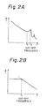
- the frequency characteristic of the servo object 11 has the resonance point f2 as shown in Fig. 2A.
- This resonance point f2 is a torsional resonance point of the servo arm such as the carriage 11b of the servo object 11.
- a servo loop for speed control which generates a target speed in accordance with a difference of a current track position with a target track and supplies to the voice coil motor a seek current corresponding to the difference between the target speed and the real speed.
- the target speed has the characteristic of maintaining the predetermined maximum speed level when the difference is above a predetermined value and of falling in proportion to a mean value of the difference, for example, when the difference is below a predetermined value.
- the target speed becomes the minimum speed level when there is a difference of one track.
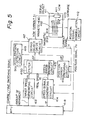
- FIG. 5 is a block diagram showing the basic constitution of another servo circuit previously proposed by the applicant to meet this demand ("related" servo circuit).
- reference numeral 411 is a magnetic disk mechanism used as the servo object. This is provided with a voice coil motor VCM 4111, a carriage 4113 mounting a magnetic head 4112, and a magnetic disk 4114.
- Reference numeral 412 is a position signal demodulation circuit which demodulates a position signal Ps showing the position of movement from servo information read by the servo head 4112 from the servo surface of the magnetic disk 4114.
- Reference numeral 413 is a target speed generating circuit which generates a target speed Vc for positioning the magnetic head 4112 of the servo object 411 at a target position in accordance with an amount of movement commanded by a main processing unit.
- Reference numeral 414 is a speed signal generating circuit which prepares a real speed Vr of the magnetic head 4112 in the servo object 411 from the position signal Ps and the current signal ic.
- the current signal ic is a compensating signal which is added for the smooth production of the real speed Vr.
- Reference numeral 415 is a speed error preparing circuit which is provided internally with a filter 4150 and generates a speed error signal ⁇ V for controlling the servo object 411 based on a speed error between the target speed Vc and the real speed Vr.
- Reference numeral 416 is a position error preparing circuit which produces a position error of the servo object 411 with respect to a target position from the position signal Ps and the current signal ic and generates the position control signal ⁇ P.
- Reference numeral 417 is a servo object drive circuit which performs processing for switching from speed control by the speed error preparing circuit 415 to the position control of the position error preparing circuit 416 by a coarse (speed control)/fine (position control) switching signal from the main processing unit, amplifies the power of the error signal ⁇ V or ⁇ P, performs processing for outputting the voice coil motor current Ic for driving the voice coil motor 4111 of the servo object 411, detects the voice coil motor current Ic, and performs processing for generating the current signal ic.
- Reference numeral 418 is a main processing unit which is constituted by a microprocessor, detects the position of the magnetic head 4112 based on the position signal Ps, outputs the remaining amount of movement, i.e.,the remaining difference, to the target speed generating circuit 413, and generates a coarse/fine switching signal near the target speed.
- Reference numeral 419 is an acceleration detecting circuit, which detects the speed error signal ⁇ V geneated by the speed error preparing circuit 415 and generates an acceleration-in-progress signal SKA which changes the band of the speed error preparing circuit 415 in accordance with the amount of seek difference during acceleration and deceleration.
- the servo circuit constructed as above performs speed control up to near the target position and then switches to position control and performs control for positioning to the target position.
- This control operation is basically the same as the servo control operations of conventional servo circuits, so the remaining explanation will primarily concentrate on the operation of the speed error preparing circuit 415 referring to Figs. 6A and 6B.
- the target speed generating circuit 413 When the speed control starts due to a command from the main processing unit 418, the target speed generating circuit 413 generates a target speed Vc during acceleration control from the amount of movement, that is, amount of difference, commanded by the main processing unit 418.
- the speed signal generating circuit 414 receives the position signal Ps from the position signal demodulation circuit 412 and the current signal ic from the servo object drive circuit 417 and prepares a real speed Vr of the servo object 411 (magnetic head).
- the speed error preparing circuit 415 generates a speed error signal ⁇ V corresponding to the speed error between the target speed Vc generated by the target speed generating circuit 413 and the real speed Vr generated by the speed signal generating circuit 414.
- te acceleration detecting circuit 419 detects from the speed error signal ⁇ V generated by the speed error preparing circuit 415 that the speed error preparing circuit 415 is in the middle of acceleration control and thereupon adds the acceleration-in-progress signal SKA to the speed error preparing circuit 415.
- the cut-off frequency f10 becomes infinitely large or higher than even the resonance point f2 of the servo object 411. Due to this, the cut-off frequency f10 of the speed error preparing circuit 415 during acceleration control becomes infinitely large or higher than even the resonance point f2 of the servo object 411 as shown in Fig. 6A.
- the finitely large cut-off frequency f10 in this case is set to a high frequency in a range where no oscillation will occur in the acceleration current.
- the servo object drive circuit 417 amplifies the power of the speed error signal ⁇ V received from the speed error preparing circuit and outputs the voice coil motor current Ic for driving by acceleration the voice coil motor 4111 of the servo object 411 and also generates a current signal ic, i.e., the detected current of the voice coil motor current Ic.
- the curve of the voice coil motor current Ic corresponding to the speed error signal ⁇ V geneated by the speed error preparing circuit 415 during acceleration control becomes a very clean, sharply inclined one, as shown by Fig. 6B, so it is possible to end the acceleration control in a short time.
- the main processing unit 418 switches to deceleration control.
- the target speed generating circuit 413 When deceleration control is switched to upon the command of the main processing unit 418, the target speed generating circuit 413 generates a target speed Vc for deceleration control.
- the speed error preparing circuit 415 generates a speed error signal ⁇ V (negative) corresponding to the speed error between a target speed Vc generated by the target speed generating circuit 413 and the real speed Vr generated by the speed signal generating circuit 414.
- the acceleration detecting circuit 419 stops the generation of the acceleration-in-progress signal SKA upon completion of the acceleration control of the speed error preparing circuit 415.
- the filter 4150 of the speed error preparing circuit 415 lowers the cut-off frequency to a frequency below the resonance point f2 of the servo object 411. At this time, the larger the difference, the lower the cut-off frequency is made. By this, the cut-off frequency of the speed error preparing circuit 415 during deceleration control is reduced to f11, f12, ... f1n the larger the amount of difference, as shown in Fig. 6A.
- the servo object drive circuit 417 amplifies the power of the speed error signal ⁇ V received from the speed error preparing circuit 415 and outputs a voice coil motor current Ic corresponding to the seek current for controlling under deceleration the voice coil motor 4111 and also generates a current signal ic, i.e., the detected current of the voice coil motor current Ic.
- the curve of the deceleration current i.e., the voice coil motor current Ic corresponding to the speed error signal ⁇ V generated by the speed error preparing circuit 415 during deceleration control
- the deceleration control time that is, the speed control time
- the cut-off frequency of the speed error preparing circuit is made to change between the times of acceleration control and deceleration control and also the cut-off frequency during deceleration control is made to change in accordance with the amount of difference, so during acceleration control, the corruption of the acceleration current supplied to the servo object can be reduced and the degree of the corruption of the deceleration current during deceleration control can be reduced the less the amount of difference, so even when the amount of difference is small, it is possible to stably shorten the speed control time. By this, it is possible to perform speed control stably and at a high speed even with an extremely small difference such as a difference of one track and thus stable, high speed seek operations become possible.
- reference numeral 4141 is a differential circuit which differentiates the position signal Ps and generates a differential speed Vps.
- Reference numeral 4143 is an amplifier which amplifies the current signal ic up to a predetermined level.
- Reference numeral 4144 is an offset adjusting circuit which generates an offset compensating signal for adjusting the offset of the real speed Vr generated from the speed signal generating circuit 414.
- Reference numerals 4145a to 4145c are variable resistors, the variable resistor 4145a being used to adjust the output gain of the amplifier 4143a, the variable resistor 4145b being used to adjust the output gain of the differential circuit 4141, and the variable resistor 4145c being used to adjust the output gain of the offset adjusting circuit 4144.
- Reference numeral 4142 is a real speed generating circuit, which amplifies and integrates the added signal of the level adjusted differential signal Vps, current speed ic, and the offset signal and prepares the real speed Vr.
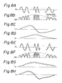
- the position signal Ps shown in Fig. 8A is applied to the differential circuit 4141 from the position signal demodulation circuit 412.
- the position signal Ps has a waveform which crosses zero each time the magnetic head passes through the track.
- the differential circuit 4141 differentiates the position signal Ps and generates a differential speed Vps shown in Fig. 8B.
- This differential speed Vps becomes zero at each of the largest points of the position signal Ps and peaks at the each point where it crosses zero.
- the envelope connecting the peaks gives the real speed Vr of the servo object 411 (magnetic head).
- the current signal ic may be added.
- the current signal ic shown in Fig. 8C from the servo object drive circuit 417 is amplified by the amplifier 4143 and added to the differential speed Vps.
- the current signal ic resembles the voice coil motor current Ic supplied to the servo object, so can effectively correct the deviations in the envelope mentioned earlier.
- the real speed generating circuit 4142 integrates and amplifies the added signal of the differential speed Vps, the current signal ic, and the offset correction signal and generates a real speed Vr having a smooth characteristic shown in Fig. 8D. Note that since an accurate real speed Vr is produced, the output gains of the current signal ic, the differential speed Vps, and the offset correction signal are initialized by the variable resistors 4145a to 4145c.
- the speed signal generating circuit 414 in the related servo circuit has a fixed frequency band irregardless of the seek difference.
- the band of the speed signal generating circuit 414 is defined by the band of the real speed generating circuit 4142, that is, the time constants of the integration resistor 4142b and capacitor 4142c.
- the position signal Ps takes on a waveform with the oscillation superposed.
- the acceleration time and the acceleration voice coil motor current Ic become large, so oscillation readily occurs.
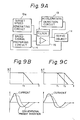
- Figures 9A to 9C are views of the principle of a first aspect of the present invention.
- a servo circuit for a magnetic disk apparatus having a target speed generating circuit 13a for generating a target speed in accordance with an amount of movement; a speed signal producing circuit 14 for producing a real speed from a position signal from a servo object 11; and a speed error generating circuit 15 for controlling the speed of the servo object 11 based on an error between the target speed and the real speed; in accordance with the amount of movement, acceleration and then deceleration control being performed for positioning at the target position, wherein provision is made of an acceleration detection circuit 19 for detecting acceleration in progress from an output of the speed error generating circuit 15 and an acceleration-in-progress detection signal of the acceleration detection generating detection circuit 12 is used for changing a cut-off frequency of the speed error generating circuit 15 during acceleration and deceleration.
- the cut-off frequency is made infinitely large or a large f2 during acceleration and is changed to a small f1 during deceleration, thereby reducing the corruption of the acceleration current during acceleration.
- the power amplifier does not function as a current source and a voltage large enough that a power source voltage is applied to the motor is input, so merely the acceleration current increases. This is equivalent to no servo control being exercised. Therefore, even if the cut-off frequency is made infinitely large or large, it is difficult for mechanical (servo object) oscillation to occur. Accordingly, the cut-off frequency may be made large, the corruption of the acceleration current reduced, and the acceleration time shortened.
- the cut-off frequency is returned to f1, so mechanical oscillation does not occur overall.
- Figure 10 is a view of the constitution of an embodiment of the first aspect of the present invention
- Fig. 11 is a view of the constitution of key parts of Fig. 10.
- portions the same as those shown in Figs. 9A to 9C are given the same reference numerals.
- the filter 151 is constituted by a parallel circuit of a resistance R with a switch SW and a capacitor C.
- Reference numeral 190 is a comparator which performs zero volt slicing of the output VCMCRT (speed error current) of the amplifier 150 and outputs a speed slice signal VSL
- reference numeral 191 is an inversion circuit which inverts the speed slice signal VSL.
- Reference numerals 192 and 193 are each three-input AND gates which generate a high level output only when all of the three inputs are high level.
- the AND gate 192 obtains the high level AND of the forward movement signal *MvF from the main processing unit (MPU) 18, the capture velocity signal *CVL generated when the real speed from the main processing unit 18 is less than a predetermined level, and the output of the comparator 190.
- the AND gate 193 obtains the high level AND of the reverse movement signal *MvR from the main processing unit 18, the capture velocity signal *CVL from the main processing unit 16, and the output of the comparator 191.
- Reference numeral 194 is an OR gate which obtains the OR of the outputs of the AND gates 192 and 193, and reference numeral 195 is an inversion circuit which inverts the output of the OR gate 194 and generates an end acceleration signal EAC.
- Reference numeral 196 is a flip-flop which is cleared by an access start *ASP from the main processing unit 18, inverts using as a clock the end acceleration signal EAC, and generates an acceleration-in-progress signal SKA from the Q output.
- Figure 12 is a waveform diagram of key parts of the embodiment of the first aspect of the present invention.
- the main processing unit 18 In forward movement, the main processing unit 18 generates a target speed FwV c in the forward direction from the target speed generating circuit 13a.
- the main processing unit 18 generates a forward movement signal *MvF. Further, in the case of a small difference and small speed, it generates a capture velocity signal *CVL from the real speed Vr.
- the speed error preparing circuit 15 the speed error between the target speed FwVc and the real speed Vr is obtained at the amplifier 150 and a speed error signal ⁇ V is generated.
- the flip-flop 196 of the acceleration detection circuit 19 is cleared by the access start signal *ASP generated along with the start of the seek operation (access), so a high level acceleration-in- progress signal SKA is generated from the Q output.
- the speed error signal ⁇ V is zero volt sliced by the comparator 190, so when the speed error signal ⁇ V is positive, a high level speed slice signal VSL is generated.
- the switch SW of the filter 151 turns on and the cut-off frequency of the amplifier 150 becomes f1.
- the speed error signal ⁇ V is restricted in band by the cut-off frequency f1.
- the main processing unit 18 when starting the access for a difference of one track, the main processing unit 18 generates an access start signal *ASP, generates a reverse direction target speed RvV c from the target speed generating circuit 13a, generates a reverse movement signal *MvR, and generates a capture velocity signal *CVL after slicing the speed signal and detecting the speed-down.
- the speed error preparing circuit 15 the speed error between the target speed RvVc and the real speed Vr is obtained and the speed error signal ⁇ V generated.
- the switch SW of the filter 151 is turned off, the cut-off frequency of the amplifier 150 is made infinitely large, and the speed error signal ⁇ V rises sharply.
- the speed error signal ⁇ V is zero volt sliced by the comparator 190 and, when the speed error signal ⁇ V is negative, a low level speed slice signal VSL is generated.
- the switch SW of the filter 151 turns off, and the cut-off frequency of the amplifier 150 becomes f1.
- the speed error signal ⁇ V is limited in band by the cut-off frequency f1.
- the switch SW of the filter 151 is turned off by the access start signal, the cut-off frequency is made infinitely large, switch SW is turned on by the end of the acceleration, and the cut-off frequency becomes f1, which is determined by the capacitor C and the resistor R.
- Figure 13 is a view explaining another embodiment of the first aspect of the present invention.
- the filter 151 is constituted by a parallel circuit of a resistor R, a capacitor C12, and a switch SW and capacitor C2. This filter 151 can be modified to the band changing circuit 4140 shown in Fig. 25A.
- the band was restricted even during acceleration, so there was absolutely no worry of mechanical oscillation, but the corruption of the acceleration current is greater than in the embodiment of Fig. 10 and the acceleration time is longer.
- Figures 14a and 14B are views of the principle of a second aspect of the present invention.
- a servo circuit for a magnetic disk apparatus provided with a servo loop which supplies a seek current based on an error signal ⁇ E between a target speed E1 and real speed E2 to a voice coil motor 210 and performs speed control on a head carriage 212 toward a target track position, wherein provision is made in the servo loop of an addition means 214 for adding a predetermined addition value (voltage) Ecc to the error signal ⁇ E at the stage of acceleration after a start of the speed control.
- the acceleration means 214 has a switching means 218 for selectively supplying the predetermined acceleration value Ecc to an addition point 216 where the error signal ⁇ E of the servo loop is input and turns on the switching means 218 at the start of the seek operation and turns off the switching means 218 at detection of completion of the acceleration.
- the acceleration means 214 has a switching means 218 for selectively supplying the predetermined acceleration value Ecc to an addition point 216 where the error signal ⁇ E of the servo loop is input and is provided with a timer means 220 which turns on the switching means 218 at the start of the seek operation and turns off the switching means 218 after the elapse of a predetermined time from the start of the seek operation.
- a predetermined acceleration value is added to the servo loop irregardless of the error between the target speed and the real speed, so during the acceleration period, the seek current can rapidly rise to the saturation level and a sufficient acceleration current can flow, so the access time for a "one difference" seek operation can be greatly reduced and demands for a higher speed magnetic disk apparatus can be met.
- Figure 15 is a view of an embodiment of the second aspect of the present invention.
- reference numeral 222 is an main processing unit constituting a control logic.
- target speed data for the seek operation is generated based on the current position of the head at that time and the target track position and a forward command c1 or reverse command signal c2 is output in accordance with the target track direction.
- Reference numeral 224 is a target speed generating circuit which converts target speed data corresponding to the forward or reverse command from the main processing unit 222 to analog signal voltage by a digital to analog converter, generates a forward target speed signal through a switch 226-1 turned on by a forward command signal c1 at the time of forward control or outputs a reverse control target speed signal through a switch 226-2 turned on by a reverse command signal c2 during reverse control.
- Reference numeral 228 is a velocity error amplifier which receives as input from the target speed generating circuit 224 a forward or reverse target speed voltage E1 through a resistor R1 or R2, finds the error signal ⁇ E with the real speed E2 input through a resistor R3, and generates an error signal ⁇ E amplified by an amplifier 230 connecting a capacitor C1 and resistor R4 to a feedback circuit.
- the output of the velocity error amplifier 228 is input to a speed control/position control switching circuit 232.
- the speed control/position control switching circuit 232 is provided with a switch 234-1 which receives as input the output of a velocity error amplifier 228 and a switch 234-2 which receives as input a position signal from a not shown position signal generating circuit.
- the switch 234-1 is turned on by a coarse signal (speed control signal) from the main processing unit 222, while the switch 234-2 is controlled by a fine signal (position control signal) from the main processing unit 222. That is, in the interval from the start of the seek operation to when the difference with respect to the target track becomes zero, the coarse signal is valid and the switch 234-1 is turned on, so speed control is performed. When the difference becomes zero, the fine signal becomes valid and the switch 234-2 is turned on, so position control maintaining the head on the target track is switched to.
- the outputs of the switches 234-1 and 234-2 are connected in common through the resistors R8 and R9, are input to an amplifier 236 provided with a feedback resistor R10 and input resistor Rll, and are supplied to a next stage power amplifier 238 through the amplifier 236.
- the output voltage from the amplifier 236 is converted to drive current by the power amplifier 238, and the drive current is passed to the voice coil motor 210.
- the voice coil motor 210 is connected mechanically to a head carriage 212 mounting a head 240 and controls the movement of the head 240 in the radial direction of a not shown disk medium.
- the servo signal from the disk medium obtained by the head 240 is given to the demodulation circuit 242.
- the real speed E2 is found by the speed detection circuit 244 from the position signal demodulated by the demodulation circuit 242 and the current signal flowing to the voice coil motor 210 detected by the power amplifier 238 and is fed back to the input stage of the amplifier 230 provided in the velocity error amplifier 228 through the resistor R3.
- the input of the amplifier 236 is provided with, as the addition means, a circuit for inputting a plus side power voltage + Ecc through the resistor R6 and the switch 218-1 and a circuit for inputting a minus side power voltage - Ecc through a resistor R7 and switch 218-2.
- the switch 218-1 for inputting the power voltage + Ecc is controlled to turn on or off by the forward acceleration signal C3, while the switch 218-2 for inputting the power voltage - Ecc is controlled to turn on or off by the reverse acceleration signal C4.
- Figure 16 is a view of an embodiment of the acceleration control circuit of the second aspect of the present invention for generating a forward acceleration signal C3 and reverse acceleration signal C4 to the switches 218-1 and 218-2 provided in the speed control/position control switching circuit 232 of Fig. 15.
- an error signal ⁇ E from the velocity error amplifier 228 is input to the acceleration control circuit. Also input from the main processing unit 222 are the forward command signal C1, reverse command signal C2, seek-in-progress signal C3 showing that the seek operation is in progress, and the seek start pulse P.
- the error signal ⁇ E is given to the plus input terminal of the comparator 246.
- the minus input terminal of the comparator 246 is grounded.
- the output of the comparator 246 is input to the AND gate 250 through the inverter 248 and is input directly to the AND gate 252.
- the AND gate 250 receives as input the forward command signal C1 and the seek-in-progress signal C3. Further, the AND gate 252 receives as input the reverse command signal C2 and the seek-in-progress signal C3. The outputs of the AND gates 250 and 252 are input to the NOR gate 254 and are further input to the clear terminal CLR of the flip-flip 258 through the inverter 256. To the clock terminal CLK of the flip-flop 258 is applied the seek start pulse P. Further, the seek start pulse P is applied to the D terminal through the capacitor. The Q output of the flip-flop 258 is input to the NAND gates 260 and 262. The NAND gate 260 receives as input the forward command signal C1 through the inverter 264.
- the NAND gate 262 receives as input the reverse command signal C2 through the inverter 266.
- the output of the NAND gate 260 becomes the forward acceleration signal C3 for adding the acceleration voltage + Ecc to the error signal DE of the servo loop, while the output of the NAND gate 262 becomes the reverse acceleration signal C4 for adding the predetermined acceleration value - Ecc to the error signal DE of the servo loop.
- Fig. 17 first, at the time t1 when a seek start pulse P is output for a "one difference" forward seek operation, along with the seek start pulse P, the main processing unit 222 makes the forward command signal C1 and the seek-in-progress signal C3 the high level. Therefore, the flip-flip 258 receiving the seek start pulse P is set and the C6 signal, serving as the Q output, falls from the high level to the low level.
- the error signal ⁇ E is at its maximum level
- the comparator 246 produces a high level output
- the AND gate 250 is inhibited by the inversion of the inverter 248, and even if both the forward command signal C1 and the seek-in-progress signal C3 become the high level, the C5 signal from the NOR gate 254 becomes the low level.
- the flip-flop 258 is set by receiving the seek start pulse P.
- the C6 signal serving as the Q output, falls from the high level to the low level
- a low level signal is input in the NAND gate 260 from the inverter 264 based on the high level forward command signal C1, so the forward acceleration signal C3, which had been the high level up to then, falls to the low level.
- the forward acceleration signal C3 for the switch 218-1 of the speed control/position control switching circuit 232 shown in Fig. 15 becomes the low level and the switch 218-1 closes.
- the power voltage of +Ecc is supplied through the resistor R6 to the input of the amplifier 236.
- target speed data corresponding to a "one difference" seek operation is given to the target speed generating circuit 224, a target speed signal E1 with an extremely small signal voltage is input through the switch 226-2 turned on by the forward command signal C1 to the velocity error amplifier 228, simultaneously the real speed signal E2 at that time is input from the speed detection circuit 44, and an error signal ⁇ E between the target speed E1 and real speed E2 is input to the amplifier 236 through a switch 234-1 in an on state by a coarse signal.
- a power voltage +Ecc input under the control of the reverse acceleration signal C3 is added to the error signal ⁇ E at the input stage of the amplifier 236, a control voltage serving as the added value ( ⁇ E + Ecc) is input by the amplifier 236 to the power amplifier 236, and, as a result, the power amplifier 238 passes a quickly rising acceleration seek current to the voice coil motor 210. Receiving this seek current, the head carriage 212 moves the head 240 to the target track.
- Figure 18 is a view of the constitution of another embodiment of the second aspect of the present invention.
- a predetermined acceleration value + Ecc or -Ecc is added to the servo loop.
- Fig. 18 the construction of the servo circuit from the main processing unit 222 to the speed detection circuit 244 is the same as that of the embodiment of Fig. 15. Only the construction of the acceleration control circuit shown in Fig. 16 differs.
- a timer signal C7 from the main processing unit 222 is input to the NAND gates 260 and 262 provided in the acceleration control circuit 270. At other inputs of the NAND gates 260 and 262 are input a forward command signal C1 and reverse command signal C2 through the inverters 264 and 266, respectively.
- a switch 218-1 provided in the speed control/position control switching circuit 232 is controlled by the forward acceleration signal C3 from the NAND gate 260. Further, the switch 218-2 is controlled by the reverse acceleration signal C4 from the NAND gate 262.
- Fig. 19 when the forward seek start pulse P is generated at the time t1, the main processing unit 222 activates the built in timer in accordance with the start of the seek operation and generates a low level timer signal C7 over the set time T. Therefore, receiving this timer signal C7, the forward acceleration signal C3 from the NAND gate 260 provided in the acceleration control circuit 270 becomes the low level, the switch 218-1 turns on, and therefore the power voltage + Ecc is compulsorily added to the error signal ⁇ E of the servo loop and the seek current rises quickly in the acceleration period, maintaining a saturation level.
- the timer signal C7 from the main processing unit 222 stops, that is, returns to the high level
- the forward acceleration signal C3 from the acceleration control circuit 270 returns to the high level
- the switch 218-1 turns off, and the addition of the power voltage + Ecc to the servo loop is stopped.
- deceleration control by the deceleration current produced by the error signal ⁇ E between the target speed signal E1 and the real speed E2 is begun.
- position control is switched to.
- the main processing unit 22 generates a low level timer signal C7 for a set time T in the same way as the forward seek operation.
- a low level reverse acceleration signal C4 is output from the acceleration control circuit 270, and the switch 218-2 is turned on, whereby the power voltage - Ecc is added to the error signal ⁇ E of the servo loop, the seek current at the acceleration stage during the reverse seek operation is quickly raised and the saturation level maintained, and, after the elapse of the set time T, the addition of the power voltage - Ecc is stopped.
- the seek current can be raised well and a sufficient acceleration characteristic can be obtained. Also, higher speeds can be realized even for seek access operations for small differences such as a difference of one track.
- Figures 20A and 20B are views explaining the principle of a third aspect of the present invention.
- a servo circuit for a magnetic disk apparatus provided with a servo loop which supplies a seek current based on an error signal ⁇ E between a target speed E1 (Vc) and real speed E2 (Vr) to a voice coil motor 310 and performs speed control on a carriage carried head 312 toward a target track position
- the servo circuit provided, at an amplifier circuit 316 positioned at a latter stage of an amplifier circuit 314 for determining the frequency characteristics of the servo loop, with a gain switching means 318 which switches a preset gain G1 to a larger gain G2 between the start of a seek operation and the completion of acceleration as shown in Fig. 20B.
- the gain switching means 318 is provided in a speed control/speed control switching circuit 316 provided at a latter stage of a velocity error circuit 314 which determines the frequency characteristic of the servo loop.
- the gain of the servo loop is amplified to a high gain compulsorily after the circuit portions which determine the frequency characteristic of the servo loop, so it is possible to quickly raise the acceleration current and achieve sufficient acceleration without the limitations of the cut-off frequency of the servo loop and it is possible to achieve faster access in a "one difference" seek operation.
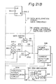
- Figure 21 is a view of the constitution of an embodiment of the third aspect of the present invention.
- the servo loop of the present invention is constituted by a servo logic 320, a target speed generating circuit 322, a forward/reverse switching circuit 324, a velocity error circuit 314, a speed control/position control switching circuit 316, a power amplifier 328 provided with a current detection circuit 340, a voice coil motor 310, a head carriage 332, and disk mechanism 330 provided with a head 312 and a disk medium 334, a position signal demodulation circuit 336, a speed signal preparing circuit 338, and an end acceleration detection circuit 342.
- the velocity error circuit 314 obtains the error between the reverse or forward target speed voltage E1 from the target speed generating circuit 322 input through the forward/reverse switching circuit 324 and the real speed voltage E2 given from the speed signal preparing circuit 338 and generates an error signal ⁇ E.
- the velocity error circuit 314 is provided with an amplifier 326.
- the feedback circuit of the amplifier 326 has connected in parallel a resistor R0 and a capacitor C0, the time constants of R0 and C0 determining the frequency characteristic of the velocity error circuit 314, i.e., the frequency characteristic of the servo loop.
- the cut-off frequency f1 is set to a frequency lower than the mechanical cut-off frequency f2 in the disk mechanism 330, that is, the mechanical cut-off frequency f2 determined by the torsional resonance point of the servo arm.
- the speed control/position control switching circuit 316 provided in the velocity error circuit 314 is provided with a switch 316-1 which is turned on by a coarse mode signal (speed control mode signal) C4 and a switch 316-2 which is turned on by the fine mode signal (position control mode signal) C5. It receives as input the error signal ⁇ E output from the velocity error circuit 314 through the switch 316-1 and receives as input the position signal from a not shown position signal generating circuit through the switch 316-2.
- the output of the switch 316-1 is input to the amplifier 350 through the resistor R5 and the output of the switch 316-2 is input through the resistor R6.
- the amplifier 350 has a resistor R8 and resistor R9 connected in parallel in the feedback circuit.
- One of the resistors, R9 is connected in series to the gain switch 318-1.
- the gain switch 318-1 is usually on. Therefore, the gain G1 of the amplifier 350 in the steady state is determined by the value of the parallel resistors R8 and R9.
- the gain switch 318-1 is turned off and the resistor R9 is cut off from the feedback circuit, the gain of the amplifier 350 becomes a high gain G2 determined by the resistor R8.
- the gain switch 318-1 is controlled to turn on and off by the D-flip-flip 318-2 provided as the gain switching control means.
- the clock terminal CLK of the D-flip-flop 318-2 has applied to it the end acceleration signal C2 from the end acceleration detection circuit 342.
- the D terminal has input to it an end acceleration signal C2 through a capacitor.
- the clear terminal CLR receives as input the seek start pulse P2 from the servo logic 320.
- the D-flip-flop 318-2 is placed in a reset state, the seek acceleration signal C3, which becomes the Q output, is at a low level, and therefore the gain switch 318-1 turns on and the steady state gain G1 is set in the amplifier 350 by the value of the parallel resistors R8 and R9.
- the D-flip-flop 318-2 is cleared, the seek acceleration signal C3 serving as the Q output becomes the high level, and the gain switch 318-1 turns off, whereby the resistor R9 is cut off from the feedback circuit and the amplifier 350 is switched to the higher gain G2.
- the D-flip-flop 318-2 reset by the seek start pulse P is again set by the end acceleration signal C2 from the end acceleration detection circuit 342 obtained next, and the acceleration signal C3 returns to the low level, whereby the gain switch 318 turns on and the original gain G1 is returned to.
- the servo logic 320 receiving the access from the host computer starts the forward control. That is, the servo logic 320 supplies the target speed generating circuit 322 with the target speed data corresponding to the amount of difference from the target track at that time, the target speed generating circuit 322 generates a target speed voltage by analog to digital conversion, and the forward switch 324-1 of the forward/reverse switching circuit turns on by the forward control command from the servo logic 320, so the target speed voltage E1 for the forward control is supplied to the velocity error circuit 314 through the switch 324-1.
- the real speed voltage E2 from the speed signal preparing circuit 338 is zero, so the error signal DE output from the amplifier 326 provided in the velocity error circuit 314 is maximum.
- the maximum level error signal ⁇ E is input to the amplifier 350 of the speed control/position control switching circuit 316 through the switch 316-1 turned on by the coarse mode signal C4.
- the gain switch 318-1 provided in the feedback circuit of the amplifier 350 receives the seek acceleration signal C3, where Q is the high level, and is switched off.
- the resistor R9 is cut off from the feedback circuit, so the switch is set to the higher gain G2 determined by the resistor R8.
- the error signal ⁇ E from the velocity error circuit 314 is amplified by the amplifier 350 by the higher gain G determined by the resistance R8, a seek current corresponding to the error signal ⁇ E is created by the power amplifier 328, and an acceleration current is passed to the voice coil motor 310 of the disk mechanism 330.
- the voice coil motor 310 which receives the acceleration seek current from the power amplifier 328, starts the speed control for moving the head 312 by the carriage 332 to the target track position of the disk medium 334.
- the speed signal preparing circuit 338 prepares the real speed voltage E2 based on the position signal from the position signal demodulation circuit 336 and the current detection signal from the current detection circuit 340 provided in the power amplifier 328, and servo control is performed for feedback to the velocity error circuit 314.
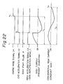
- the error signal DE from the amplifier 326 becomes zero voltage, so the fact that the zero voltage has been reached is detected by the end acceleration detection circuit 342, the end acceleration signal C2 rises to a high level with respect to the D-flip-flop 318-2 as shown at the time t2 in Fig. 22, and the D-flip-flop 318-2, which had been in the reset state up until then, is returned once again to the set state at the time of detection of the end of the acceleration. Therefore, the seek acceleration signal C3, which serves as the Q output, returns to the low level from the high level, and the gain switch 318-1 turns on, whereby the resistor R9 is connected to the feedback circuit and the original gain G1 is returned to.
- the amplifier 350 switches the normal gain G1 to the higher gain G2 in the period from the start of the seek operation to the end of the acceleration.
- deceleration control is performed based on the error signal ⁇ E between the target speed voltage E1 and the real speed voltage E2.
- the switch 316-2 turns on due to the fine mode signal C5 from the servo logic 320, and position control (fine control) is switched to for control so that the head traces the target track.
- the "one difference” seek operation of the related art suffered from the effects of the cut-off frequency f1 in the frequency characteristic determined by the time constants of the resistor R0 and the capacitor C0 provided in the velocity error circuit 314.
- the constant gain seek current of the servo loop of the related art rose slowly during acceleration. If the seek operation is considered to begin at the time t1, a long seek time T2 extending until the time t4 is required compared with the seek time T1 of the third aspect of the present invention.
- the gain of the amplifier 320 provided in the speed control/position control switching circuit 316 at the latter stage of the velocity error circuit 314 determining the frequency characteristic of the servo loop is switched to a higher gain during the acceleration, so the seek current during the acceleration period can be raised well without being limited by the frequency characteristic of the servo loop and sufficient acceleration is made possible, whereby it is possible to greatly reduce the access time in a "one difference" seek operation and realize high speed access.
- the velocity error circuit 314 of circuit elements for determining the frequency characteristic of the servo loop, so a gain switching means was provided in the speed control/position control switching circuit 316 serving as the latter stage of the velocity error circuit 314, but the third aspect of the present invention is not limited to this and it is of course possible to provide, in a suitable portion of the amplifier circuit positioned at the latter stage of the amplifier circuit determining the frequency characteristic in the loop of the servo circuit, a gain switching means for switching to a gain higher than the usual gain in the period from the start of the seek operation to the end of the acceleration.
- the acceleration/deceleration period of the seek current is a value close to the cut-off frequency of the servo loop, it is possible to quickly raise the acceleration current and sufficiently accelerate without being limited by the cut-off frequency of the servo loop and it is possible to achieve a much faster access in a "one difference" seek operation.
- Figure 23 is a block diagram of the basic constitution of a fourth aspect of the present invention.
- a servo circuit for a magnetic disk apparatus which performs speed control over a servo object based on a speed error between a target speed and a real speed, wherein provision is made of a speed signal generating circuit 414A which generates the real speed Vr of the servo object based on a position signal Ps of the servo object 411 from a position signal demodulation circuit, the speed signal generating circuit provided with a band changing circuit 4140 for changing the band of a speed signal producing circuit 414B in accordance to a seek difference.
- a speed signal generating circuit 414A which generates the real speed Vr of the servo object based on a position signal Ps of the servo object 411 from a position signal demodulation circuit
- the speed signal generating circuit provided with a band changing circuit 4140 for changing the band of a speed signal producing circuit 414B in accordance to a seek difference.
- a frequency f31 close to the resonance point f2 of the servo object is set to.
- the larger the seek difference the lower the frequency f32,... f3n than the resonance point f2 is set to.
- the speed signal generating circuit is provided with a differentiating circuit 4141 which differentiates the position signal to generate a speed, a real speed generating circuit 4142 which generates the real speed based on the differential signal, and a band changing circuit 4140 which changes the band of the real speed generating circuit 4142 according to the seek difference.
- a differentiating circuit 4141 which differentiates the position signal to generate a speed
- a real speed generating circuit 4142 which generates the real speed based on the differential signal
- a band changing circuit 4140 which changes the band of the real speed generating circuit 4142 according to the seek difference.
- Fig. 24A to 24D are the same waveforms as that of Figs. 8D to 8F, these figures are used for explaining the fourth aspect of the present invention.
- the speed signal generating circuit 414A is changed in band by the band changing circuit 4140 in accordance with the seek difference. As shown in Fig. 24A, the larger the seek difference, the small the band set to.
- the speed signal generating circuit 414A generates a real speed Vr of the servo object based on the position signal Ps.
- the real speed Vr is prepared, for example, by differentiating the position signal Ps and producing a differential speed Vps, then integrating (smoothening) the differential signal Vps.
- the band of the speed error preparing circuit is set wide, but the band of the speed signal generating circuit 4141 is also set correspondingly wide, so the acceleration control time is shortened and a high speed seek operation is possible.
- the oscillation frequency generated also becomes high, so even if the bands of the speed signal generating circuit 414A and speed error preparing circuit are made wide, it is possible to effectively suppress the oscillation component and to prevent the occurrence of loop resonance.
- the band of the speed signal generating circuit 414A is narrow, so as shown in Fig. 24B, even if oscillation occurs in the position signal Ps due to the mechanical oscillation generated in the servo object, at the real speed Vr output, the oscillation component is effectively suppressed and does not appear (Fig. 24D). Therefore, the occurrence of loop resonance is prevented and a stable seek operation is made possible.
- the band of the speed signal generating circuit 414A is made narrow, the time constant of the speed signal generating circuit 414A becomes large, so the time for speed control increases, but since the overall speed control time is long, the degree of that increase is small and the increase in the speed control time in the case of such a seek difference does not pose a problem in practice.
- the band of the speed signal preparing circuit is changed in accordance with the seek difference, so irregardless of the magnitude of the seek difference, it is possible to effectively prevent the occurrence of loop resonance in seek control and it is possible to achieve stable, high speed seek operations even in the case of a small seek difference such as a difference of one track.
- Figures 24A to 24D are waveform diagrams used for explaining the operation of the embodiment.
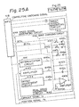
- Figure 25 is a block diagram of the constitution of an embodiment of the speed signal generating circuit.
- the speed signal generating circuit 414A and the band changing circuit 4140 are as explained in Fig. 23. Other portions corresponding in constitution to those in the related servo circuit are given the same reference numerals.
- reference numeral 411 is a servo object
- 412 is a position signal demodulation circuit for generating a position signal Ps.
- Reference numeral 413 is a target speed generating circuit for generating a target speed Vc
- 415 is a speed error preparing circuit which generates a speed error signal ⁇ V from the speed error between the target speed Vc and the real speed Vr generated by the speed signal generating circuit 414A.
- Reference numeral 416 is a position error preparing circuit which produces a position error ⁇ P based on the position signal Ps and the current signal ic.
- Reference numeral 417 is a servo object drive circuit which amplifies the power of the speed error signal ⁇ V during speed (coarse) control and the position error signal ⁇ P during position (fine) control, geneates a voice coil motor current Ic for driving the servo object 411, supplies it to the servo object 411, detects the voice coil motor current Ic, and generates the current signal ic.
- Reference numeral 418 is a main processing unit which supplies a band changing signal BCX1 to BCXn to the band changing circuit 4140 of the speed signal generating circuit 414A, sends the necessary control signals to the circuits, and controls the overall seek operation of the servo circuit.
- Reference numeral 419 is an acceleration detecting circuit, which detects the speed error signal ⁇ V generated by the speed error preparing circuit 415 and generates an acceleration-in-progress signal SKA which changes the band of the speed error preparing circuit 415 in accordance with the amount of seek difference during acceleration and deceleration.
- 4142 is a real speed generating circuit.
- 4142a is a amplifier such as an operational amplifier
- 4142b is an integration resistance
- 4142c is an integration capacitor
- Reference numeral 4142d is an offset compensation resistor of the amplifier 4142a.
- Reference numeral 4144 is an offset adjustment circuit which adjusts the offset of the real speed Vr.
- Reference numerals 4145a, 4145b, and 4145c are variable resistors for adjusting the gains of the differential circuit 4141, the amplifier 4143, and the offset adjustment circuit 4144.
- the capacitance of the integration capacitor 4142c is a small capacitance required in the case of the minimum seek difference (difference of one track).
- reference numerals 41461 to 4146 n are capacitors for band adjustment.
- Reference numerals 41471 to 4147 n are switches provided in series with the corresponding capacitors 41461 to 4146 n and are turned on and off by the band changing signals BCX1 to BCXn from the main processing unit 418.
- the operations of the circuits other than the real speed preparing operation of the speed signal generating circuit 414A and the overall seek operation are the same as the operations of the circuits and the overall seek operation of the related servo circuit, so the following explanation will concentrate on the operation of the speed signal generating circuit 414A.
- the main processing unit 418 Before the start of the seek operation, the main processing unit 418 turns on the band changing signal BCXi corresponding to the seek difference.
- the band changing circuit 4140 of the speed signal generating circuit 414A when receiving this band changing signal BCXi, turns on the corresponding switch 4147i.
- the capacitor 4146i becomes parallel with the resistor 4142b along with the capacitor 4142c, so the band of the real speed generating circuit 4142, that is, the speed signal generating circuit 414A, is set to be narrower the larger the seek difference, as shown in Fig. 24A.
- the offset adjustment circuit 4144 generates an offset compensation signal which performs adjustment so that the offset of the real speed Vr generated by the speed signal generating circuit 414A becomes zero. Further, the values of the variable resistors 4146a to 4146c are initialized corresponding to the output gains of the differential circuit 4141, the amplifier 4143, and the off-set adjustment circuit 4144 so that the correct real speed Vr is produced.
- the differential circuit 4141 differentiates the position signal Ps input from the position signal demodulation circuit 412 and generates the differential signal Vps (Figs. 24B and 24C). Note that Figs. 24B and 24C shows the case where there is oscillation in the position signal Ps and the differential signal Vps.
- the amplifier 4143 amplifies the current signal ic generated from the servo object 411.
- the real speed generating circuit 4142 amplifies and integrates the differential signal Vps, current signal ic, and offset adjustment signal adjusted in level by the variable resistors 4145a to 4145c and prepares the real speed Vr.
- the real speed generating circuit 4142 is band restricted by the band changing circuit 4140, so even if there is oscillation in the differential speed Vps, this oscillation component is suppressed and does not appear in the output real speed Vr (Figs. 24C and 24D).
- the oscillation is suppressed and does not appear either in the speed error signal ⁇ V generated by the speed error preparing circuit 415 based on the speed error between the real speed Vr and the target speed Vc from the target speed generating circuit 413 and the voice coil motor current Ic of the servo object drive circuit 417.
- the band changing circuit 4140 may be made a filter in construction and inserted at the output side or input side of the real speed generating circuit 4142, and that band changed and controlled in accordance with the amount of seek difference.
- a plurality of capacitors can be combined in the band changing circuit 4140 of Fig. 25 so as to obtain the desired capacitance.
- speed signal generating circuit of the fourth aspect of the present invention can of course be applied to servo circuits other than the related servo circuit.
- the fourth aspect of the present invention changes the band of the speed signal generating circuit in accordance with the amount of seek difference, so it is possible to effectively prevent the occurrence of loop resonance during the seek control irregardless of the magnitude of the seek difference. Due to this, it is possible to achieve stable, high speed seek operations even with small seek differences such as a difference of one track.
- the fifth aspect is the modification of the first aspect of the present invention.
- Fig. 26 is a graph for explaining the characteristic of the fifth aspect of the present invention.
- the cut-off frequency f10 of the filter is set to the infinite frequency or the higher frequency than the resonance point frequency f2.
- the cut-off frequency f10 is set to the extent without occurring the vibration of the acceleration current.
- the main processing unit 18 changes from the acceleration control to the deceleration control, and the acceleration-in-progress signal SKA is stopped.
- the filter of the speed error preparing circuit 15 is set the lower frequency than the resonance point frequency f2 when the speed error preparing circuit 15 starts to perform the deceleration control. In this case, the cut-off frequency becomes lower in accordance with the larger difference amount. Accordingly, in the deceleration control, the cut-off frequency of the filter of the speed error preparing circuit lowers as shown by f11 , f12 , --- f 1n in accordance with the larger difference amount.
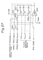
- Figures 27 and 28 are filter circuits for the fifth aspect of the present invention.
- the filter shown in Fig. 28 is the same structure as the filter shown in Fig. 27 except that the capacitor 5152a having smaller capacitance is added in parallel to the resistor 5151.
- the switch 5153 is switched by the acceleration-in-progress signal SKA from the acceleration detection circuit 19.
- the switches 5153a to 5153n are switched by the filter switching signals FCS1 to FCS n . These switching operation are the same as the fourth aspect of the present invention.
- the capacitor 5152a shown in Fig. 28 is set to the smaller value in the extent without occurring the vibration of the servo object.
Abstract
Description
- The present invention relates to a servo circuit for a magnetic disk apparatus which performs speed control over a servo object based on an error between a target speed and a real speed, more particularly relates to ones which perform speed control by passing a seek current corresponding to the error between the target speed and the real speed to a voice coil motor and to one having a speed signal generating circuit for finding the real speed.
- Servo circuits are used in magnetic disk apparatuses for positioning magnetic heads on specific tracks. In such servo circuits, it is desired to reduce the time required for the speed control and to shorten the access time and to obtain stable positioning even with higher speeds.
- In particular, in recent years, higher speeds have been achieved in the seek access operations, which move and stop a head in a disk apparatus at a target track position. Along with the higher speeds of seek access operations, much higher speeds have been sought for so-called "one difference" seek access operations wherein the heads are moved to the adjoining track position. A demand has therefore arisen for a servo circuit with a high response commensurate with the higher speeds of "one difference" seek operations.
- Explaining the related art in more detail, in a servo circuit, speed control is used up to near the target position, then position control is switched to so as to control the positioning to the target position. However, the frequency characteristic of the servo object has a resonance point, i.e., a resonance point of the servo arm such as the carriage of the servo object. If the frequency of a speed control signal, explained later, appears in the band which covers this resonance point, mechanical oscillation appears during the seek operation and therefore there is no hope for improvement of the floating stability of the magnetic head and the stability after switching to fine control.
- The frequency band of an amplifier of a speed error detection circuit, explained later, is determined by the time constant of a resistor and capacitor of a filter. The cut-off frequency must be made smaller than the resonance point. In recent years, however, higher speed access has become desirable. With a "one difference" seek operation, the acceleration/deceleration current cycle of the speed control signal becomes close to the cut-off frequency. Therefore, the current waveform, in particular, the current waveform during acceleration, becomes corrupted and no further current can be passed. Since it is difficult to raise the resonance point, the problem arises that it is difficult to shorten the time for speed control.
- In another related art, provision is made of a servo loop for speed control which generates a target speed in accordance with a difference of a current track position from a target track and supplies to a voice coil motor a seek current corresponding to the difference between the target speed and the real speed. Here, the target speed has the characteristic of maintaining a predetermined maximum speed level when the difference is above a predetermined amount and of falling in proportion to a mean value of the difference, for example, when the difference is under a predetermined amount. The target speed becomes the minimum speed level in the case of a difference of one track.
- However, with such a servo circuit, since acceleration is performed by passing a seek current corresponding to the difference between a target speed and real speed, determined by the difference at the start of the seek operation, when the target speed level is extremely small, such as with a "one difference" seek operation, the rise of the acceleration current flowing to the voice coil motor becomes slow.
- That is, in a "one difference" seek operation, when the seek current begins to flow at the start of the seek operation and the real speed appears, the target speed level is extremely small, so the difference between the real speed and target speed disappears and the seek current is suppressed. As a result, the seek current at the time of acceleration becomes triangular in form, the rise of the acceleration current deteriorates, and the access time of a "one difference" seek operation becomes longer.
- In still another servo circuit, provision is made of an additional speed error preparing circuit. This circuit, however, sometimes suffers from loop resonance, which prevents a normal seek operation. Such loop resonance occurs more easily the larger the seek difference, but if this is prevented by limiting the bands of component circuits so as to try to suppress the oscillation component, the time for the speed control becomes longer and a high speed seek operation, in particular, a high speed seek operation for a small amount of difference such as a difference of one track becomes difficult.
- A first object of the present invention is to reduce the corruption of the acceleration current at the time of a small difference and shorten the speed control time.
- The first object is achieved by a servo circuit for a magnetic disk apparatus having a target speed generating circuit for generating a target speed in accordance with an amount of movement; a speed signal producing circuit for producing a real speed from a position signal from a servo object; and a speed error generating circuit for controlling the speed of the servo object based on an error between the target speed and the real speed; in accordance with the amount of movement, acceleration and then deceleration control being performed for positioning at the target position, wherein provision is made of an acceleration detection circuit for detecting acceleration in progress from an output of the speed error generating circuit, and an acceleration-in-progress detection signal of the acceleration detection generating detection circuit is used for changing a cut-off frequency of the speed error generating circuit between acceleration and deceleration.
- A second object of the present invention is raise the acceleration current excellently and achieve higher speeds even with a small difference.
- This is achieved by a servo circuit for a magnetic disk apparatus provided with a servo loop which supplies a seek current based on an error signal between a target speed and real speed to a voice coil motor and performs speed control on a head carriage toward a target track position, provided in the servo loop with an addition means for adding a predetermined addition value to the error at the stage of acceleration after a start of the speed control.
- A third object of the present invention is to raise the acceleration current excellently and achieve high speed access even if the acceleration/deceleration cycle of the seek current is a "one difference" seek operation close to a cut-off frequency of a servo loop.
- This is achieved by a servo circuit for a magnetic disk apparatus provided with a servo loop which supplies a seek current based on an error between a target speed and real speed to a voice coil motor and performs speed control on a head carriage toward a target track position, provided, at an amplifier circuit positioned at a latter stage of an amplifier circuit for determining the frequency characteristic of the servo loop, with a gain switching means which switches a preset gain to a larger gain between the start of a seek operation and the completion of acceleration.
- A fourth object of the present invention is to effectively prevent the occurrence of loop resonance during seek control irregardless of the magnitude of the seek difference and to enable a stable, high speed seek operation even in the case of a small difference.
- This is achieved by a servo circuit for a magnetic disk apparatus which performs speed control over a servo object based on a speed error between a target speed and a real speed, provided with a speed signal generating circuit which generates the real speed of the servo object based on a position signal of the servo object, the speed signal generating circuit provided with a band changing circuit for changing the band of a speed signal producing circuit in accordance with a seek difference.
-
- Figure 1 and Figs. 2A and 2B are views explaining the prior art;
- Fig. 3 is a view explaining problems in the prior art;
- Fig. 4 is a view explaining a conventional "one difference" seek operation;
- Fig. 5 is is a view explaining the constitution of a related servo circuit;
- Figs. 6A and 6B are views explaining the operational characteristics of the related servo circuit;
- Fig. 7 is a view explaining the constitution of a speed signal generating circuit of the related servo circuit;
- Figs. 8A to 8H are views explaining operational waveforms of the speed signal generating circuit of the related servo circuit;
- Figs. 9A to 9C are views of the principle of a first aspect of the present invention;
- Fig. 10 is a view of the constitution of an embodiment of the first aspect of the present invention;
- Fig. 11 is a view of the constitution of main parts of the constitution of Fig. 10;
- Fig. 12 is a waveform diagram of important parts of an embodiment of the first aspect of the present invention;
- Fig. 13 is a view explaining another embodiment of the first aspect of the present invention;
- Figs. 14A and 14B are views explaining the principle of a second aspect of the present invention;
- Fig. 15 is a view of the constitution of an embodiment of the second aspect of the present invention;
- Fig. 16 is a view of the constitution of an embodiment of an acceleration control circuit of the second aspect of the present invention;
- Fig. 17 is a timing chart of the operation of the embodiment of Figs. 15 and 16;
- Fig. 18 is a view of the constitution of another embodiment of the second aspect of the present invention;
- Fig. 19 is an operational timing chart of the embodiment of Fig. 18;
- Figs. 20A and 20B are views explaining the principle of a third aspect of the present invention;
- Fig. 21 is a view of the constitution of an embodiment of the third aspect of the present invention;
- Fig. 22 is an operational timing chart of the third aspect of the present invention;
- Fig. 23 is a view explaining the basic constitution of a fourth aspect of the present invention;
- Figs. 24A to 24D are views explaining the operational characteristics of the speed signal generating circuit of the fourth aspect of the present invention;
- Fig. 25 is a view explaining the constitution of an embodiment of the fourth aspect of the present invention;
- Fig. 26 is a graph for explaining the characteristic of the fifth aspect of the present invention; and
- Fig. 27 and 28 are filter circuits for the fifth aspect of the present invention.
- Before describing the preferred embodiments, a more detailed explanation will be given of the related art for background purposes.
- Figure 1 is a view explaining a prior art. In the figure, 11 is a servo object, i.e., a magnetic disk mechanism, which has a
voice coil motor 11a, acarriage 11b for carrying amagnetic head 110, and amagnetic disk 11c. -
Reference numeral 12 is a position signal demodulation circuit which demodulates a position signal Ps from servo information read from the servo surface of amagnetic disk speed generating circuit 13a in accordance with the forward/reverse switching signal of themain processing unit 18. -
Reference numeral 14 is a speed signal preparing circuit which prepares a real speed Vr from a position signal Ps and a current signal ic, mentioned later.Reference numeral 15 is a speed error preparing circuit which generates a speed control current (signal) in accordance with a speed error ΔV between a target speed Vc and a real speed Vr and has anamplifier 150 for generating the speed error ΔV and afilter 151. -
Reference numeral 16 is a position error preparing circuit which produces a position error from the position signal Ps and current signal ic and generates a position control signal; and 17a is a coarse/fine switching unit which switches from speed control of the speederror preparing circuit 15 to position control of the positionerror preparing circuit 16 by a coarse (speed control)/fine (position control) switching signal from the main processing unit. -
Reference numeral 17b is a power amplifier which amplifies the output of theswitching unit 17a and drives thevoice coil motor 11a of themagnetic disk mechanism 11; and 17c is a current detection circuit which detects the drive current of thepower amplifier 17b and generates a current signal ic. -
Reference numeral 18 is a main processing unit which is constituted by a microprocessor, detects the position in accordance with the position signal Ps, outputs a remaining movement to a targetspeed generating circuit 13a, generates a forward/reverse switching signal in accordance with the forward/reverse direction, and generates a coarse/fine switching signal near the target position. - In this servo circuit, speed control is used up to near the target position, then position control is switched to so as to control the positioning to the target position.
- However, the frequency characteristic of the
servo object 11 has the resonance point f2 as shown in Fig. 2A. - This resonance point f2 is a torsional resonance point of the servo arm such as the
carriage 11b of theservo object 11. - If the frequency of the speed control signal appears in the band which covers this resonance point, mechanical vibration appears during the seek operation (movement) and therefore there is no hope for improvement of the floating stability of the
magnetic head 110 and the stability after switching to fine control. - Therefore, the frequency band of the
amplifier 150 of the speederror detection circuit 15 is determined by the time constants of the resistor and capacitor of thefilter 151, and the cut-off frequency f1 of the frequency band shown in Fig. 2B must be made smaller than f2, for example, f2 = 2f1 to 1.5 f1. - In recent years, however, higher speed access times have become desirable. With a "one difference" seek operation, as shown in Fig. 3, the acceleration/deceleration current IC cycle of the speed control signal has become close to the cut-off frequency f1. Therefore, as shown by the solid line of Fig. 3, the current waveform of the IC, in particular, the current waveform during acceleration, becomes corrupted and no further current can be passed, as shown by the dotted line. Since it is difficult to raise the resonance point f2 of the mechanical characteristics, the problem arises that it is difficult to shorten the time for speed control.
- In another related art, provision is made of a servo loop for speed control which generates a target speed in accordance with a difference of a current track position with a target track and supplies to the voice coil motor a seek current corresponding to the difference between the target speed and the real speed.
- Here, the target speed has the characteristic of maintaining the predetermined maximum speed level when the difference is above a predetermined value and of falling in proportion to a mean value of the difference, for example, when the difference is below a predetermined value. The target speed becomes the minimum speed level when there is a difference of one track.
- However, with such a servo circuit, since acceleration is performed by passing a seek current corresponding to a difference between the target speed and real speed determined by the difference at the start of the seek operation, when the target speed level is extremely small, such as with a "one difference" seek operation, the rise of the acceleration current flowing to the voice coil motor becomes slow
- That is, as shown in Fig. 4, in a "one difference" seek operation, when the seek current begins to flow at the start of the seek operation at the time t1 and the real speed appears, the target speed level is extremely small, so the difference between the real speed and target speed disappears and the seek current is suppressed. As a result, the seek current at the time of acceleration becomes triangular in form, the rise of the acceleration current 0A deteriorates, and the access time of a "one difference" seek operation becomes longer.
- Figure 5 is a block diagram showing the basic constitution of another servo circuit previously proposed by the applicant to meet this demand ("related" servo circuit). In Fig. 5,
reference numeral 411 is a magnetic disk mechanism used as the servo object. This is provided with a voicecoil motor VCM 4111, acarriage 4113 mounting amagnetic head 4112, and amagnetic disk 4114. -
Reference numeral 412 is a position signal demodulation circuit which demodulates a position signal Ps showing the position of movement from servo information read by theservo head 4112 from the servo surface of themagnetic disk 4114. -
Reference numeral 413 is a target speed generating circuit which generates a target speed Vc for positioning themagnetic head 4112 of theservo object 411 at a target position in accordance with an amount of movement commanded by a main processing unit. -
Reference numeral 414 is a speed signal generating circuit which prepares a real speed Vr of themagnetic head 4112 in theservo object 411 from the position signal Ps and the current signal ic. The current signal ic is a compensating signal which is added for the smooth production of the real speed Vr. -
Reference numeral 415 is a speed error preparing circuit which is provided internally with afilter 4150 and generates a speed error signal ΔV for controlling theservo object 411 based on a speed error between the target speed Vc and the real speed Vr. -
Reference numeral 416 is a position error preparing circuit which produces a position error of theservo object 411 with respect to a target position from the position signal Ps and the current signal ic and generates the position control signal ΔP. -
Reference numeral 417 is a servo object drive circuit which performs processing for switching from speed control by the speederror preparing circuit 415 to the position control of the positionerror preparing circuit 416 by a coarse (speed control)/fine (position control) switching signal from the main processing unit, amplifies the power of the error signal ΔV or ΔP, performs processing for outputting the voice coil motor current Ic for driving thevoice coil motor 4111 of theservo object 411, detects the voice coil motor current Ic, and performs processing for generating the current signal ic. -
Reference numeral 418 is a main processing unit which is constituted by a microprocessor, detects the position of themagnetic head 4112 based on the position signal Ps, outputs the remaining amount of movement, i.e.,the remaining difference, to the targetspeed generating circuit 413, and generates a coarse/fine switching signal near the target speed. -
Reference numeral 419 is an acceleration detecting circuit, which detects the speed error signal ΔV geneated by the speederror preparing circuit 415 and generates an acceleration-in-progress signal SKA which changes the band of the speederror preparing circuit 415 in accordance with the amount of seek difference during acceleration and deceleration. - The servo circuit constructed as above performs speed control up to near the target position and then switches to position control and performs control for positioning to the target position. This control operation is basically the same as the servo control operations of conventional servo circuits, so the remaining explanation will primarily concentrate on the operation of the speed
error preparing circuit 415 referring to Figs. 6A and 6B. - When the speed control starts due to a command from the
main processing unit 418, the targetspeed generating circuit 413 generates a target speed Vc during acceleration control from the amount of movement, that is, amount of difference, commanded by themain processing unit 418. - Further, the speed
signal generating circuit 414 receives the position signal Ps from the positionsignal demodulation circuit 412 and the current signal ic from the servoobject drive circuit 417 and prepares a real speed Vr of the servo object 411 (magnetic head). - The speed
error preparing circuit 415 generates a speed error signal ΔV corresponding to the speed error between the target speed Vc generated by the targetspeed generating circuit 413 and the real speed Vr generated by the speedsignal generating circuit 414. - On the other hand, te
acceleration detecting circuit 419 detects from the speed error signal ΔV generated by the speederror preparing circuit 415 that the speederror preparing circuit 415 is in the middle of acceleration control and thereupon adds the acceleration-in-progress signal SKA to the speederror preparing circuit 415. - When the
filter 4150 of the speederror preparing circuit 415 receives the acceleration-in-progress signal SKA from theacceleration detecting circuit 419, the cut-off frequency f10 becomes infinitely large or higher than even the resonance point f2 of theservo object 411. Due to this, the cut-off frequency f10 of the speederror preparing circuit 415 during acceleration control becomes infinitely large or higher than even the resonance point f2 of theservo object 411 as shown in Fig. 6A. The finitely large cut-off frequency f10 in this case is set to a high frequency in a range where no oscillation will occur in the acceleration current. - The servo
object drive circuit 417 amplifies the power of the speed error signal ΔV received from the speed error preparing circuit and outputs the voice coil motor current Ic for driving by acceleration thevoice coil motor 4111 of theservo object 411 and also generates a current signal ic, i.e., the detected current of the voice coil motor current Ic. - By this, the curve of the voice coil motor current Ic corresponding to the speed error signal ΔV geneated by the speed
error preparing circuit 415 during acceleration control becomes a very clean, sharply inclined one, as shown by Fig. 6B, so it is possible to end the acceleration control in a short time. - When the acceleration control is ended, the
main processing unit 418 switches to deceleration control. - When deceleration control is switched to upon the command of the
main processing unit 418, the targetspeed generating circuit 413 generates a target speed Vc for deceleration control. The speederror preparing circuit 415 generates a speed error signal ΔV (negative) corresponding to the speed error between a target speed Vc generated by the targetspeed generating circuit 413 and the real speed Vr generated by the speedsignal generating circuit 414. - On the other hand, the
acceleration detecting circuit 419 stops the generation of the acceleration-in-progress signal SKA upon completion of the acceleration control of the speederror preparing circuit 415. - When the speed
error preparing circuit 415 enters deceleration control, thefilter 4150 of the speederror preparing circuit 415 lowers the cut-off frequency to a frequency below the resonance point f2 of theservo object 411. At this time, the larger the difference, the lower the cut-off frequency is made. By this, the cut-off frequency of the speederror preparing circuit 415 during deceleration control is reduced to f11, f12, ... f1n the larger the amount of difference, as shown in Fig. 6A. - The servo
object drive circuit 417 amplifies the power of the speed error signal ΔV received from the speederror preparing circuit 415 and outputs a voice coil motor current Ic corresponding to the seek current for controlling under deceleration thevoice coil motor 4111 and also generates a current signal ic, i.e., the detected current of the voice coil motor current Ic. - By this, the curve of the deceleration current, i.e., the voice coil motor current Ic corresponding to the speed error signal ΔV generated by the speed
error preparing circuit 415 during deceleration control, becomes as shown in Fig. 6B. That is, there is less corruption of the deceleration curve the smaller the amount of difference, and the deceleration control time, that is, the speed control time, falls such as tn, ... t2, t1. - In the above way, the cut-off frequency of the speed error preparing circuit is made to change between the times of acceleration control and deceleration control and also the cut-off frequency during deceleration control is made to change in accordance with the amount of difference, so during acceleration control, the corruption of the acceleration current supplied to the servo object can be reduced and the degree of the corruption of the deceleration current during deceleration control can be reduced the less the amount of difference, so even when the amount of difference is small, it is possible to stably shorten the speed control time. By this, it is possible to perform speed control stably and at a high speed even with an extremely small difference such as a difference of one track and thus stable, high speed seek operations become possible.
- Next, an explanation will be made of the constitution and operation of the speed
signal generating circuit 414 referring to Fig. 7 and Figs. 8A to 8H. In Fig. 7,reference numeral 4141 is a differential circuit which differentiates the position signal Ps and generates a differential speed Vps.Reference numeral 4143 is an amplifier which amplifies the current signal ic up to a predetermined level. -
Reference numeral 4144 is an offset adjusting circuit which generates an offset compensating signal for adjusting the offset of the real speed Vr generated from the speedsignal generating circuit 414. -
Reference numerals 4145a to 4145c are variable resistors, thevariable resistor 4145a being used to adjust the output gain of the amplifier 4143a, thevariable resistor 4145b being used to adjust the output gain of thedifferential circuit 4141, and thevariable resistor 4145c being used to adjust the output gain of the offset adjustingcircuit 4144. -
Reference numeral 4142 is a real speed generating circuit, which amplifies and integrates the added signal of the level adjusted differential signal Vps, current speed ic, and the offset signal and prepares the real speed Vr. - In this construction, the position signal Ps shown in Fig. 8A is applied to the
differential circuit 4141 from the positionsignal demodulation circuit 412. The position signal Ps has a waveform which crosses zero each time the magnetic head passes through the track. Thedifferential circuit 4141 differentiates the position signal Ps and generates a differential speed Vps shown in Fig. 8B. This differential speed Vps becomes zero at each of the largest points of the position signal Ps and peaks at the each point where it crosses zero. The envelope connecting the peaks gives the real speed Vr of the servo object 411 (magnetic head). - If just the differential signal Vps generated from the
differential circuit 4141 is given to the realspeed generating circuit 4142, differentiation is performed and the envelope of the differential speed Vps is obtained. In this case, at places where the peak interval of the differential speed Vps is small, that is, at places of fast speed of the Vr, a good envelope characteristic is obtained, but at places with large peak intervals, that is, places of slow speed (starting and ending times of seek operations), good envelope characteristics cannot be obtained. To correct the deviations in the envelope characteristics, the current signal ic may be added. - The current signal ic shown in Fig. 8C from the servo
object drive circuit 417 is amplified by theamplifier 4143 and added to the differential speed Vps. The current signal ic resembles the voice coil motor current Ic supplied to the servo object, so can effectively correct the deviations in the envelope mentioned earlier. - The real
speed generating circuit 4142 integrates and amplifies the added signal of the differential speed Vps, the current signal ic, and the offset correction signal and generates a real speed Vr having a smooth characteristic shown in Fig. 8D. Note that since an accurate real speed Vr is produced, the output gains of the current signal ic, the differential speed Vps, and the offset correction signal are initialized by thevariable resistors 4145a to 4145c. - The speed
signal generating circuit 414 in the related servo circuit has a fixed frequency band irregardless of the seek difference. The band of the speedsignal generating circuit 414 is defined by the band of the realspeed generating circuit 4142, that is, the time constants of theintegration resistor 4142b andcapacitor 4142c. - Therefore, when oscillation is generated during seek acceleration control due to the mechanical resonance of the
servo object 411, as shown in Fig. 8E, the position signal Ps takes on a waveform with the oscillation superposed. When the amount of movement of the servo object 411 (magnetic head), that is, the amount of seek difference, is large, the acceleration time and the acceleration voice coil motor current Ic become large, so oscillation readily occurs. - When oscillation is generated in the position signal Ps in this way, oscillation is also caused in the differential speed Vps as shown in Fig. 8F, and oscillation is caused in the real speed Vr generated by the real speed generating circuit 4142 (Fig. 8G).
- Since this oscillating real speed Vr is received and oscillation occurs in the speed error signal ΔV generated by the speed
error preparing circuit 415, oscillation also occurs in the voice coil motor current Ic generated by the servo object drive circuit 417 (Fig. 8H). - As a result, the amplitude of the
servo object 411 is amplified, loop resonance occurs, and a normal seek operation is no longer possible. Such loop resonance occurs more easily the larger the seek difference, but if this is prevented by limiting the bands of one or both of the speedsignal generating circuit 414 and the speederror preparing circuit 415 so as to try to suppress the oscillation component, the time for the speed control becomes longer and a high speed seek operation, in particular, a high speed seek operation with a small amount of difference such as a difference of one track, becomes difficult. This is a problem of not only the related servo circuit, but conventional servo circuits as well. - Figures 9A to 9C are views of the principle of a first aspect of the present invention.
- According to the first aspect of the present invention, there is provided a servo circuit for a magnetic disk apparatus having a target
speed generating circuit 13a for generating a target speed in accordance with an amount of movement; a speedsignal producing circuit 14 for producing a real speed from a position signal from aservo object 11; and a speederror generating circuit 15 for controlling the speed of theservo object 11 based on an error between the target speed and the real speed; in accordance with the amount of movement, acceleration and then deceleration control being performed for positioning at the target position, wherein provision is made of anacceleration detection circuit 19 for detecting acceleration in progress from an output of the speederror generating circuit 15 and an acceleration-in-progress detection signal of the acceleration detection generatingdetection circuit 12 is used for changing a cut-off frequency of the speederror generating circuit 15 during acceleration and deceleration. - Explaining the mode of operation of the first aspect of the present invention in more detail, as shown by Figs. 9B and 9C, the cut-off frequency is made infinitely large or a large f2 during acceleration and is changed to a small f1 during deceleration, thereby reducing the corruption of the acceleration current during acceleration.
- During acceleration, the power amplifier does not function as a current source and a voltage large enough that a power source voltage is applied to the motor is input, so merely the acceleration current increases. This is equivalent to no servo control being exercised. Therefore, even if the cut-off frequency is made infinitely large or large, it is difficult for mechanical (servo object) oscillation to occur. Accordingly, the cut-off frequency may be made large, the corruption of the acceleration current reduced, and the acceleration time shortened.
- Due to this, as shown by the solid lines of Figs. 9B and 9C, the acceleration time is shortened compared with the prior art shown by the dotted line and therefore the speed control time can be shortened.
- Further, during deceleration, the cut-off frequency is returned to f1, so mechanical oscillation does not occur overall.
- Figure 10 is a view of the constitution of an embodiment of the first aspect of the present invention, and Fig. 11 is a view of the constitution of key parts of Fig. 10. In the figure, portions the same as those shown in Figs. 9A to 9C are given the same reference numerals.
- In the figure, the
filter 151 is constituted by a parallel circuit of a resistance R with a switch SW and a capacitor C. -
Reference numeral 190 is a comparator which performs zero volt slicing of the output VCMCRT (speed error current) of theamplifier 150 and outputs a speed slice signal VSL, andreference numeral 191 is an inversion circuit which inverts the speed slice signal VSL. -
Reference numerals gate 192 obtains the high level AND of the forward movement signal *MvF from the main processing unit (MPU) 18, the capture velocity signal *CVL generated when the real speed from themain processing unit 18 is less than a predetermined level, and the output of thecomparator 190. The ANDgate 193 obtains the high level AND of the reverse movement signal *MvR from themain processing unit 18, the capture velocity signal *CVL from themain processing unit 16, and the output of thecomparator 191. -
Reference numeral 194 is an OR gate which obtains the OR of the outputs of the ANDgates reference numeral 195 is an inversion circuit which inverts the output of theOR gate 194 and generates an end acceleration signal EAC. -
Reference numeral 196 is a flip-flop which is cleared by an access start *ASP from themain processing unit 18, inverts using as a clock the end acceleration signal EAC, and generates an acceleration-in-progress signal SKA from theQ output. - Figure 12 is a waveform diagram of key parts of the embodiment of the first aspect of the present invention.
- In forward movement, the
main processing unit 18 generates a target speed FwVc in the forward direction from the targetspeed generating circuit 13a. Themain processing unit 18 generates a forward movement signal *MvF. Further, in the case of a small difference and small speed, it generates a capture velocity signal *CVL from the real speed Vr. - In the speed
error preparing circuit 15, the speed error between the target speed FwVc and the real speed Vr is obtained at theamplifier 150 and a speed error signal ΔV is generated. - At this time, the flip-
flop 196 of theacceleration detection circuit 19 is cleared by the access start signal *ASP generated along with the start of the seek operation (access), so a high level acceleration-in- progress signal SKA is generated from theQ output. - By this, the switch SW of the
filter 151 turns off, the cut-off frequency of theamplifier 150 becomes infinitely large, and the speed error signal ΔC rises sharply. - The speed error signal ΔV is zero volt sliced by the
comparator 190, so when the speed error signal ΔV is positive, a high level speed slice signal VSL is generated. - Therefore, a high level output is generated from the AND
gate 192 and a low level end acceleration signal EAC is generated through theOR gate 194 and theinversion circuit 195. - When the speed error signal ΔV becomes zero, the speed slice signal VSL of the
comparator 190 becomes the low level, the output of the ANDgate 192 becomes the low level, the end acceleration signal EAC through theOR gate 194 andinversion circuit 195 becomes the high level, the flip-flop 196 inverts using this point of change as a clock, and the acceleration-in-progress signal SKA of theQ output becomes the low level. - Therefore, the switch SW of the
filter 151 turns on and the cut-off frequency of theamplifier 150 becomes f1. - In the succeeding deceleration period, the speed error signal ΔV is restricted in band by the cut-off frequency f1.
- Due to this, the current VCMCRT flowing through the
power amplifier 17b to thevoice coil motor 11a rises substantially linearly during the acceleration period as shown in Fig. 12. - On the other hand, in reverse movement, when starting the access for a difference of one track, the
main processing unit 18 generates an access start signal *ASP, generates a reverse direction target speed RvVc from the targetspeed generating circuit 13a, generates a reverse movement signal *MvR, and generates a capture velocity signal *CVL after slicing the speed signal and detecting the speed-down. - In the speed
error preparing circuit 15, the speed error between the target speed RvVc and the real speed Vr is obtained and the speed error signal ΔV generated. - At this time, due to the access start signal *ASP, the flip-
flop 196 of theacceleration detection circuit 19 is cleared, so a high level acceleration-in-progress signal SKA is generated from theQ output. - By this, the switch SW of the
filter 151 is turned off, the cut-off frequency of theamplifier 150 is made infinitely large, and the speed error signal ΔV rises sharply. - The speed error signal ΔV is zero volt sliced by the
comparator 190 and, when the speed error signal ΔV is negative, a low level speed slice signal VSL is generated. - Therefore, a high level output is generated from the AND
gate 193, and a low level end acceleration signal EAC is generated through theOR gate 194 andinversion circuit 195. - When the speed error signal ΔV becomes zero, the speed slice signal VSL of the
comparator 190 becomes high level, the output of the ANDgate 193 becomes low level, the end acceleration signal EAC through theOR gate 194 andinversion circuit 195 becomes high level, the flip-flop 196 inverts using this point of change as a clock, and the acceleration-in-progress signal SKA of theQ output becomes low level. - Therefore, the switch SW of the
filter 151 turns off, and the cut-off frequency of theamplifier 150 becomes f1. - As a result, during the deceleration period, the speed error signal ΔV is limited in band by the cut-off frequency f1.
- By this, the current VCMCRT flowing through the
power amplifier 17b to thevoice coil motor 11a rises substantially linearly during the acceleration period as shown in Fig. 12. - In this way, in a "one difference" seek operation, the switch SW of the
filter 151 is turned off by the access start signal, the cut-off frequency is made infinitely large, switch SW is turned on by the end of the acceleration, and the cut-off frequency becomes f1, which is determined by the capacitor C and the resistor R. - Figure 13 is a view explaining another embodiment of the first aspect of the present invention.
- In this embodiment, the
filter 151 is constituted by a parallel circuit of a resistor R, a capacitor C12, and a switch SW and capacitor C2. Thisfilter 151 can be modified to theband changing circuit 4140 shown in Fig. 25A. - Therefore, when the switch SW is turned ON, as shown in Fig. 9C, the cut-off frequency changes to f1, and when the switch SW is turned OFF, the cut-off frequency changes to f2.
- By the same operation as in Fig. 10 and Fig. 11, in a "one difference" seek operation, during acceleration, the switch SW is turned OFF by the acceleration-in-progress signal SKA and the cut-off frequency becomes f2, so the corruption of the acceleration signal is reduced, while during deceleration, the switch SW is turned ON and the cut-off frequency becomes f1.
- In this example, the band was restricted even during acceleration, so there was absolutely no worry of mechanical oscillation, but the corruption of the acceleration current is greater than in the embodiment of Fig. 10 and the acceleration time is longer.
- In the above embodiments of the first aspect of the present invention, the explanation was made taking as an example a magnetic disk apparatus, but the invention may be applied to other apparatuses as well and it is possible to change the cut-off frequency with respect to the desired distance of movement.
- Figures 14a and 14B are views of the principle of a second aspect of the present invention.
- According to the second aspect of the present invention, there is provided a servo circuit for a magnetic disk apparatus provided with a servo loop which supplies a seek current based on an error signal ΔE between a target speed E1 and real speed E2 to a
voice coil motor 210 and performs speed control on ahead carriage 212 toward a target track position, wherein provision is made in the servo loop of an addition means 214 for adding a predetermined addition value (voltage) Ecc to the error signal ΔE at the stage of acceleration after a start of the speed control. - Preferably, as shown in Fig. 14A, the acceleration means 214 has a switching means 218 for selectively supplying the predetermined acceleration value Ecc to an
addition point 216 where the error signal ΔE of the servo loop is input and turns on the switching means 218 at the start of the seek operation and turns off the switching means 218 at detection of completion of the acceleration. - More preferably, as shown in Fig. 14B, the acceleration means 214 has a switching means 218 for selectively supplying the predetermined acceleration value Ecc to an
addition point 216 where the error signal ΔE of the servo loop is input and is provided with a timer means 220 which turns on the switching means 218 at the start of the seek operation and turns off the switching means 218 after the elapse of a predetermined time from the start of the seek operation. - In the servo circuit for a magnetic disk apparatus according to the second aspect of the present invention, even in a "one difference" seek operation where the target speed is extremely small, a predetermined acceleration value is added to the servo loop irregardless of the error between the target speed and the real speed, so during the acceleration period, the seek current can rapidly rise to the saturation level and a sufficient acceleration current can flow, so the access time for a "one difference" seek operation can be greatly reduced and demands for a higher speed magnetic disk apparatus can be met.
- Figure 15 is a view of an embodiment of the second aspect of the present invention.
- In Fig. 15,
reference numeral 222 is an main processing unit constituting a control logic. When an access signal is received from a host computer, target speed data for the seek operation is generated based on the current position of the head at that time and the target track position and a forward command c1 or reverse command signal c2 is output in accordance with the target track direction.Reference numeral 224 is a target speed generating circuit which converts target speed data corresponding to the forward or reverse command from themain processing unit 222 to analog signal voltage by a digital to analog converter, generates a forward target speed signal through a switch 226-1 turned on by a forward command signal c1 at the time of forward control or outputs a reverse control target speed signal through a switch 226-2 turned on by a reverse command signal c2 during reverse control. -
Reference numeral 228 is a velocity error amplifier which receives as input from the target speed generating circuit 224 a forward or reverse target speed voltage E1 through a resistor R1 or R2, finds the error signal ΔE with the real speed E2 input through a resistor R3, and generates an error signal ΔE amplified by anamplifier 230 connecting a capacitor C1 and resistor R4 to a feedback circuit. - The output of the
velocity error amplifier 228 is input to a speed control/positioncontrol switching circuit 232. - The speed control/position
control switching circuit 232 is provided with a switch 234-1 which receives as input the output of avelocity error amplifier 228 and a switch 234-2 which receives as input a position signal from a not shown position signal generating circuit. The switch 234-1 is turned on by a coarse signal (speed control signal) from themain processing unit 222, while the switch 234-2 is controlled by a fine signal (position control signal) from themain processing unit 222. That is, in the interval from the start of the seek operation to when the difference with respect to the target track becomes zero, the coarse signal is valid and the switch 234-1 is turned on, so speed control is performed. When the difference becomes zero, the fine signal becomes valid and the switch 234-2 is turned on, so position control maintaining the head on the target track is switched to. - The outputs of the switches 234-1 and 234-2 are connected in common through the resistors R8 and R9, are input to an
amplifier 236 provided with a feedback resistor R10 and input resistor Rll, and are supplied to a nextstage power amplifier 238 through theamplifier 236. The output voltage from theamplifier 236 is converted to drive current by thepower amplifier 238, and the drive current is passed to thevoice coil motor 210. Thevoice coil motor 210 is connected mechanically to ahead carriage 212 mounting ahead 240 and controls the movement of thehead 240 in the radial direction of a not shown disk medium. - The servo signal from the disk medium obtained by the
head 240 is given to the demodulation circuit 242. The real speed E2 is found by thespeed detection circuit 244 from the position signal demodulated by the demodulation circuit 242 and the current signal flowing to thevoice coil motor 210 detected by thepower amplifier 238 and is fed back to the input stage of theamplifier 230 provided in thevelocity error amplifier 228 through the resistor R3. - This part of the constitution of the servo circuit is the same as in the prior art. In the second aspect of the present invention, however, there is the addition and new provision, at the input stage of the
amplifier 236 provided in the speed control/positioncontrol switching circuit 232, of an acceleration means for compulsorily adding a predetermined acceleration voltage at the acceleration stage of the start of the seek operation. - That is, the input of the
amplifier 236 is provided with, as the addition means, a circuit for inputting a plus side power voltage + Ecc through the resistor R6 and the switch 218-1 and a circuit for inputting a minus side power voltage - Ecc through a resistor R7 and switch 218-2. The switch 218-1 for inputting the power voltage + Ecc is controlled to turn on or off by the forward acceleration signal C3, while the switch 218-2 for inputting the power voltage - Ecc is controlled to turn on or off by the reverse acceleration signal C4. - Figure 16 is a view of an embodiment of the acceleration control circuit of the second aspect of the present invention for generating a forward acceleration signal C3 and reverse acceleration signal C4 to the switches 218-1 and 218-2 provided in the speed control/position
control switching circuit 232 of Fig. 15. - In Fig. 16, an error signal ΔE from the
velocity error amplifier 228 is input to the acceleration control circuit. Also input from themain processing unit 222 are the forward command signal C1, reverse command signal C2, seek-in-progress signal C3 showing that the seek operation is in progress, and the seek start pulse P. - The error signal ΔE is given to the plus input terminal of the
comparator 246. The minus input terminal of thecomparator 246 is grounded. When the error signal ΔE becomes zero voltage, that is, after the start of the seek operation, the point of time when the real speed voltage E2 reaches the target speed voltage E1 and matches the same is detected as the point of the end of the acceleration and the high level output is inverted to the low level output. - The output of the
comparator 246 is input to the ANDgate 250 through theinverter 248 and is input directly to the ANDgate 252. - The AND
gate 250 receives as input the forward command signal C1 and the seek-in-progress signal C3. Further, the ANDgate 252 receives as input the reverse command signal C2 and the seek-in-progress signal C3. The outputs of the ANDgates gate 254 and are further input to the clear terminal CLR of the flip-flip 258 through theinverter 256. To the clock terminal CLK of the flip-flop 258 is applied the seek start pulse P. Further, the seek start pulse P is applied to the D terminal through the capacitor. TheQ output of the flip-flop 258 is input to theNAND gates NAND gate 260 receives as input the forward command signal C1 through theinverter 264. Further, theNAND gate 262 receives as input the reverse command signal C2 through theinverter 266. The output of theNAND gate 260 becomes the forward acceleration signal C3 for adding the acceleration voltage + Ecc to the error signal DE of the servo loop, while the output of theNAND gate 262 becomes the reverse acceleration signal C4 for adding the predetermined acceleration value - Ecc to the error signal DE of the servo loop. - Next, the operation of the embodiment of Figs. 15 and 16 will be explained referring to the operation timing chart of Fig. 17.
- In Fig. 17, first, at the time t1 when a seek start pulse P is output for a "one difference" forward seek operation, along with the seek start pulse P, the
main processing unit 222 makes the forward command signal C1 and the seek-in-progress signal C3 the high level. Therefore, the flip-flip 258 receiving the seek start pulse P is set and the C6 signal, serving as theQ output, falls from the high level to the low level. Further, at the start of the seek operation, the error signal ΔE is at its maximum level, thecomparator 246 produces a high level output, the ANDgate 250 is inhibited by the inversion of theinverter 248, and even if both the forward command signal C1 and the seek-in-progress signal C3 become the high level, the C5 signal from the NORgate 254 becomes the low level. - In this way, the flip-
flop 258 is set by receiving the seek start pulse P. When the C6 signal, serving as theQ output, falls from the high level to the low level, a low level signal is input in theNAND gate 260 from theinverter 264 based on the high level forward command signal C1, so the forward acceleration signal C3, which had been the high level up to then, falls to the low level. - Due to the operation of the acceleration control circuit shown in Fig. 16, the forward acceleration signal C3 for the switch 218-1 of the speed control/position
control switching circuit 232 shown in Fig. 15 becomes the low level and the switch 218-1 closes. By this, the power voltage of +Ecc is supplied through the resistor R6 to the input of theamplifier 236. - On the other hand, at the same time as the start of the seek operation, target speed data corresponding to a "one difference" seek operation is given to the target
speed generating circuit 224, a target speed signal E1 with an extremely small signal voltage is input through the switch 226-2 turned on by the forward command signal C1 to thevelocity error amplifier 228, simultaneously the real speed signal E2 at that time is input from the speed detection circuit 44, and an error signal ΔE between the target speed E1 and real speed E2 is input to theamplifier 236 through a switch 234-1 in an on state by a coarse signal. - Therefore, a power voltage +Ecc input under the control of the reverse acceleration signal C3 is added to the error signal ΔE at the input stage of the
amplifier 236, a control voltage serving as the added value (ΔE + Ecc) is input by theamplifier 236 to thepower amplifier 236, and, as a result, thepower amplifier 238 passes a quickly rising acceleration seek current to thevoice coil motor 210. Receiving this seek current, thehead carriage 212 moves thehead 240 to the target track. - Next, at the time t2, when the error signal ΔE for the
comparator 246 shown in Fig. 16 reaches zero voltage, the output of thecomparator 246 inverts to the low level and the end of the acceleration is detected. The low level output of thecomparator 246 places the ANDgate 250 in an enable state through theinverter 248, the C5 signal from the NORgate 254 becomes the high level, the flip-flop 258 is reset, and, as a result, the C6 signal of theQ output is returned to the high level. Therefore, by the forward acceleration signal C3 from the ANDgate 260 returning to the high level, the switch 218-1 provided in Fig. 15 is turned off and the acceleration control by the addition of the power voltage + Ecc is released. - Therefore, after the time t2, a deceleration current flows based on the error signal ΔE produced by the error between the target speed signal E1 and the real speed signal E2. At the end of the seek operation at the time t3, the coarse signal returns to the high level, the speed control ends, and simultaneously the fine signal changes from the high level to the low level. When the switch 234-2 turns on, position control based on the position signal is switched to. Further, at the time t4, if a seek start pulse P for the reverse seek operation is generated based on an access from a host computer, the reverse command signal C2 from the
main processing unit 222 becomes the high level. In the same way as the forward seek operation, the reverse acceleration signal C4 from theNAND gate 262 provided in the acceleration control circuit of Fig. 16 becomes the low level, the switch 218-2 of Fig. 15 turns on, whereby the power voltage - Ecc is compulsorily applied to the servo loop, and the seek current of the "one difference" seek operation rises well at the acceleration stage. - Figure 18 is a view of the constitution of another embodiment of the second aspect of the present invention.
- In the embodiment of Fig. 18, for a predetermined time from the start of the seek operation, a predetermined acceleration value + Ecc or -Ecc is added to the servo loop.
- In Fig. 18, the construction of the servo circuit from the
main processing unit 222 to thespeed detection circuit 244 is the same as that of the embodiment of Fig. 15. Only the construction of the acceleration control circuit shown in Fig. 16 differs. - That is, in the embodiment of Fig. 18, new provision is made in the
main processing unit 222 of a timer function by a timer means generating a timer signal C7 during a predetermined time from the start of the seek operation. A timer signal C7 from themain processing unit 222 is input to theNAND gates NAND gates inverters control switching circuit 232 is controlled by the forward acceleration signal C3 from theNAND gate 260. Further, the switch 218-2 is controlled by the reverse acceleration signal C4 from theNAND gate 262. - Next, an explanation will be made of the operation of the embodiment of Fig. 18 referring to the operational timing chart of Fig. 19.
- In Fig. 19, when the forward seek start pulse P is generated at the time t1, the
main processing unit 222 activates the built in timer in accordance with the start of the seek operation and generates a low level timer signal C7 over the set time T. Therefore, receiving this timer signal C₇, the forward acceleration signal C3 from theNAND gate 260 provided in the acceleration control circuit 270 becomes the low level, the switch 218-1 turns on, and therefore the power voltage + Ecc is compulsorily added to the error signal ΔE of the servo loop and the seek current rises quickly in the acceleration period, maintaining a saturation level. - At the time t2 after the elapse of a set time T from the start of the seek operation, the timer signal C7 from the
main processing unit 222 stops, that is, returns to the high level, the forward acceleration signal C3 from the acceleration control circuit 270 returns to the high level, the switch 218-1 turns off, and the addition of the power voltage + Ecc to the servo loop is stopped. After the time t2, deceleration control by the deceleration current produced by the error signal ΔE between the target speed signal E1 and the real speed E2 is begun. At the time t3, position control is switched to. - Further, at the time t4, if a seek pulse for a reverse seek operation is obtained, the main processing unit 22 generates a low level timer signal C7 for a set time T in the same way as the forward seek operation. A low level reverse acceleration signal C4 is output from the acceleration control circuit 270, and the switch 218-2 is turned on, whereby the power voltage - Ecc is added to the error signal ΔE of the servo loop, the seek current at the acceleration stage during the reverse seek operation is quickly raised and the saturation level maintained, and, after the elapse of the set time T, the addition of the power voltage - Ecc is stopped.
- As explained above, according to the second aspect of the present invention, by the compulsory addition of a predetermined acceleration value to the error signal of the servo loop at the stage of acceleration at the start of the seek operation, even in a "one difference" seek operation where the target speed signal is extremely small, the seek current can be raised well and a sufficient acceleration characteristic can be obtained. Also, higher speeds can be realized even for seek access operations for small differences such as a difference of one track.
- Figures 20A and 20B are views explaining the principle of a third aspect of the present invention.
- According to the third aspect of the present invention, there is provided a servo circuit for a magnetic disk apparatus provided with a servo loop which supplies a seek current based on an error signal ΔE between a target speed E1 (Vc) and real speed E2 (Vr) to a
voice coil motor 310 and performs speed control on a carriage carriedhead 312 toward a target track position, the servo circuit provided, at anamplifier circuit 316 positioned at a latter stage of anamplifier circuit 314 for determining the frequency characteristics of the servo loop, with a gain switching means 318 which switches a preset gain G1 to a larger gain G2 between the start of a seek operation and the completion of acceleration as shown in Fig. 20B. - Preferably, the gain switching means 318 is provided in a speed control/speed
control switching circuit 316 provided at a latter stage of avelocity error circuit 314 which determines the frequency characteristic of the servo loop. - In the servo circuit of a magnetic disk apparatus according to the third aspect of the present invention, even when the acceleration/ deceleration current cycle during a "one difference" seek operation becomes a value close to the cut-off frequency of the amplifier, during the acceleration period, the gain of the servo loop is amplified to a high gain compulsorily after the circuit portions which determine the frequency characteristic of the servo loop, so it is possible to quickly raise the acceleration current and achieve sufficient acceleration without the limitations of the cut-off frequency of the servo loop and it is possible to achieve faster access in a "one difference" seek operation.
- Figure 21 is a view of the constitution of an embodiment of the third aspect of the present invention.
- In Fig. 21, first, the servo loop of the present invention is constituted by a
servo logic 320, a targetspeed generating circuit 322, a forward/reverse switching circuit 324, avelocity error circuit 314, a speed control/positioncontrol switching circuit 316, apower amplifier 328 provided with acurrent detection circuit 340, avoice coil motor 310, ahead carriage 332, anddisk mechanism 330 provided with ahead 312 and adisk medium 334, a positionsignal demodulation circuit 336, a speedsignal preparing circuit 338, and an endacceleration detection circuit 342. - The
velocity error circuit 314 obtains the error between the reverse or forward target speed voltage E1 from the targetspeed generating circuit 322 input through the forward/reverse switching circuit 324 and the real speed voltage E2 given from the speedsignal preparing circuit 338 and generates an error signal ΔE. Thevelocity error circuit 314 is provided with an amplifier 326. The feedback circuit of the amplifier 326 has connected in parallel a resistor R0 and a capacitor C0, the time constants of R0 and C0 determining the frequency characteristic of thevelocity error circuit 314, i.e., the frequency characteristic of the servo loop. The cut-off frequency f1 is set to a frequency lower than the mechanical cut-off frequency f2 in thedisk mechanism 330, that is, the mechanical cut-off frequency f2 determined by the torsional resonance point of the servo arm. - The speed control/position
control switching circuit 316 provided in thevelocity error circuit 314 is provided with a switch 316-1 which is turned on by a coarse mode signal (speed control mode signal) C4 and a switch 316-2 which is turned on by the fine mode signal (position control mode signal) C5. It receives as input the error signal ΔE output from thevelocity error circuit 314 through the switch 316-1 and receives as input the position signal from a not shown position signal generating circuit through the switch 316-2. The output of the switch 316-1 is input to theamplifier 350 through the resistor R5 and the output of the switch 316-2 is input through the resistor R6. Theamplifier 350 has a resistor R8 and resistor R9 connected in parallel in the feedback circuit. One of the resistors, R9, is connected in series to the gain switch 318-1. The gain switch 318-1 is usually on. Therefore, the gain G1 of theamplifier 350 in the steady state is determined by the value of the parallel resistors R8 and R9. On the other hand, when the gain switch 318-1 is turned off and the resistor R9 is cut off from the feedback circuit, the gain of theamplifier 350 becomes a high gain G2 determined by the resistor R8. - The gain switch 318-1 is controlled to turn on and off by the D-flip-flip 318-2 provided as the gain switching control means. The clock terminal CLK of the D-flip-flop 318-2 has applied to it the end acceleration signal C2 from the end
acceleration detection circuit 342. The D terminal has input to it an end acceleration signal C2 through a capacitor. Further, the clear terminal CLR receives as input the seek start pulse P2 from theservo logic 320. - Therefore, in the steady state, the D-flip-flop 318-2 is placed in a reset state, the seek acceleration signal C3, which becomes the
Q output, is at a low level, and therefore the gain switch 318-1 turns on and the steady state gain G1 is set in theamplifier 350 by the value of the parallel resistors R8 and R9. When an access is received from the host computer and theservo logic 320 generates a seek start pulse P, the D-flip-flop 318-2 is cleared, the seek acceleration signal C3 serving as theQ output becomes the high level, and the gain switch 318-1 turns off, whereby the resistor R9 is cut off from the feedback circuit and theamplifier 350 is switched to the higher gain G2. The D-flip-flop 318-2 reset by the seek start pulse P is again set by the end acceleration signal C2 from the endacceleration detection circuit 342 obtained next, and the acceleration signal C3 returns to the low level, whereby thegain switch 318 turns on and the original gain G1 is returned to. - Next, an explanation will be made of the operation of the embodiment of Fig. 21 referring to the operational timing chart of Fig. 22.
- In Fig. 22, first, assume that at the time t1, the
servo logic 320 receiving the access from the host computer starts the forward control. That is, theservo logic 320 supplies the targetspeed generating circuit 322 with the target speed data corresponding to the amount of difference from the target track at that time, the targetspeed generating circuit 322 generates a target speed voltage by analog to digital conversion, and the forward switch 324-1 of the forward/reverse switching circuit turns on by the forward control command from theservo logic 320, so the target speed voltage E1 for the forward control is supplied to thevelocity error circuit 314 through the switch 324-1. - In the initial state, the real speed voltage E2 from the speed
signal preparing circuit 338 is zero, so the error signal DE output from the amplifier 326 provided in thevelocity error circuit 314 is maximum. The maximum level error signal ΔE is input to theamplifier 350 of the speed control/positioncontrol switching circuit 316 through the switch 316-1 turned on by the coarse mode signal C4. At that time, since the D-flip-flop 318-2 receives the seek start pulse P from theservo logic 320 at the time t1 and is in the reset state, the gain switch 318-1 provided in the feedback circuit of theamplifier 350 receives the seek acceleration signal C3, whereQ is the high level, and is switched off. The resistor R9 is cut off from the feedback circuit, so the switch is set to the higher gain G2 determined by the resistor R8. - Therefore, the error signal ΔE from the
velocity error circuit 314 is amplified by theamplifier 350 by the higher gain G determined by the resistance R8, a seek current corresponding to the error signal ΔE is created by thepower amplifier 328, and an acceleration current is passed to thevoice coil motor 310 of thedisk mechanism 330. - The
voice coil motor 310, which receives the acceleration seek current from thepower amplifier 328, starts the speed control for moving thehead 312 by thecarriage 332 to the target track position of thedisk medium 334. Along with the speed control, the speedsignal preparing circuit 338 prepares the real speed voltage E2 based on the position signal from the positionsignal demodulation circuit 336 and the current detection signal from thecurrent detection circuit 340 provided in thepower amplifier 328, and servo control is performed for feedback to thevelocity error circuit 314. - When the real speed voltage E2 increases under this servo control and the target speed voltage E1 is reached, the error signal DE from the amplifier 326 becomes zero voltage, so the fact that the zero voltage has been reached is detected by the end
acceleration detection circuit 342, the end acceleration signal C2 rises to a high level with respect to the D-flip-flop 318-2 as shown at the time t2 in Fig. 22, and the D-flip-flop 318-2, which had been in the reset state up until then, is returned once again to the set state at the time of detection of the end of the acceleration. Therefore, the seek acceleration signal C3, which serves as theQ output, returns to the low level from the high level, and the gain switch 318-1 turns on, whereby the resistor R9 is connected to the feedback circuit and the original gain G1 is returned to. - That is, the
amplifier 350 switches the normal gain G1 to the higher gain G2 in the period from the start of the seek operation to the end of the acceleration. - At the time t2, after the end of the acceleration, deceleration control is performed based on the error signal ΔE between the target speed voltage E1 and the real speed voltage E2. At the time t3, the difference from the target track becomes zero, the switch 316-2 turns on due to the fine mode signal C5 from the
servo logic 320, and position control (fine control) is switched to for control so that the head traces the target track. - Compared with this "one difference" seek operation of the third aspect of the present invention, the "one difference" seek operation of the related art suffered from the effects of the cut-off frequency f1 in the frequency characteristic determined by the time constants of the resistor R0 and the capacitor C0 provided in the
velocity error circuit 314. As shown in Fig. 22, the constant gain seek current of the servo loop of the related art rose slowly during acceleration. If the seek operation is considered to begin at the time t1, a long seek time T2 extending until the time t4 is required compared with the seek time T1 of the third aspect of the present invention. - As opposed to this, in the third aspect of the present invention, even if the cycle of the acceleration/deceleration period of the seek current in a "one difference" seek operation approaches the cut-off frequency f1 of the servo loop, the gain of the
amplifier 320 provided in the speed control/positioncontrol switching circuit 316 at the latter stage of thevelocity error circuit 314 determining the frequency characteristic of the servo loop is switched to a higher gain during the acceleration, so the seek current during the acceleration period can be raised well without being limited by the frequency characteristic of the servo loop and sufficient acceleration is made possible, whereby it is possible to greatly reduce the access time in a "one difference" seek operation and realize high speed access. - Further, in the above embodiment, provision was made in the
velocity error circuit 314 of circuit elements for determining the frequency characteristic of the servo loop, so a gain switching means was provided in the speed control/positioncontrol switching circuit 316 serving as the latter stage of thevelocity error circuit 314, but the third aspect of the present invention is not limited to this and it is of course possible to provide, in a suitable portion of the amplifier circuit positioned at the latter stage of the amplifier circuit determining the frequency characteristic in the loop of the servo circuit, a gain switching means for switching to a gain higher than the usual gain in the period from the start of the seek operation to the end of the acceleration. - As explained above, according to the third aspect of the present invention, even in a "one difference" seek operation where the acceleration/deceleration period of the seek current is a value close to the cut-off frequency of the servo loop, it is possible to quickly raise the acceleration current and sufficiently accelerate without being limited by the cut-off frequency of the servo loop and it is possible to achieve a much faster access in a "one difference" seek operation.
- Figure 23 is a block diagram of the basic constitution of a fourth aspect of the present invention.
- According to the fourth aspect of the present invention, as shown in Fig. 23, there is provided a servo circuit for a magnetic disk apparatus which performs speed control over a servo object based on a speed error between a target speed and a real speed, wherein provision is made of a speed
signal generating circuit 414A which generates the real speed Vr of the servo object based on a position signal Ps of theservo object 411 from a position signal demodulation circuit, the speed signal generating circuit provided with aband changing circuit 4140 for changing the band of a speed signal producing circuit 414B in accordance to a seek difference. As shown in Fig. 24A, when the seek difference is small, a frequency f31 close to the resonance point f2 of the servo object is set to. The larger the seek difference, the lower the frequency f32,... f3n than the resonance point f2 is set to. - Preferably, the speed signal generating circuit is provided with a differentiating
circuit 4141 which differentiates the position signal to generate a speed, a realspeed generating circuit 4142 which generates the real speed based on the differential signal, and aband changing circuit 4140 which changes the band of the realspeed generating circuit 4142 according to the seek difference. - The operation of the fourth aspect of the present invention will now be explained referring to the graphs of Figs. 24A to 24D. Although Fig. 24B to 24C are the same waveforms as that of Figs. 8D to 8F, these figures are used for explaining the fourth aspect of the present invention.
- Before the start of the seek operation, the speed
signal generating circuit 414A is changed in band by theband changing circuit 4140 in accordance with the seek difference. As shown in Fig. 24A, the larger the seek difference, the small the band set to. - The speed
signal generating circuit 414A generates a real speed Vr of the servo object based on the position signal Ps. The real speed Vr is prepared, for example, by differentiating the position signal Ps and producing a differential speed Vps, then integrating (smoothening) the differential signal Vps. - In the case of a small difference such as in a "one difference" seek operation, as explained in Fig. 5, the band of the speed error preparing circuit is set wide, but the band of the speed
signal generating circuit 4141 is also set correspondingly wide, so the acceleration control time is shortened and a high speed seek operation is possible. In the case of a small difference, the oscillation frequency generated also becomes high, so even if the bands of the speedsignal generating circuit 414A and speed error preparing circuit are made wide, it is possible to effectively suppress the oscillation component and to prevent the occurrence of loop resonance. - When the seek difference is large, the band of the speed
signal generating circuit 414A is narrow, so as shown in Fig. 24B, even if oscillation occurs in the position signal Ps due to the mechanical oscillation generated in the servo object, at the real speed Vr output, the oscillation component is effectively suppressed and does not appear (Fig. 24D). Therefore, the occurrence of loop resonance is prevented and a stable seek operation is made possible. - If the band of the speed
signal generating circuit 414A is made narrow, the time constant of the speedsignal generating circuit 414A becomes large, so the time for speed control increases, but since the overall speed control time is long, the degree of that increase is small and the increase in the speed control time in the case of such a seek difference does not pose a problem in practice. - As mentioned above, the band of the speed signal preparing circuit is changed in accordance with the seek difference, so irregardless of the magnitude of the seek difference, it is possible to effectively prevent the occurrence of loop resonance in seek control and it is possible to achieve stable, high speed seek operations even in the case of a small seek difference such as a difference of one track.
- An embodiment of the fourth aspect of the present invention will now be explained with reference to Figs. 24A to 24D and Fig. 25. Figures 24A to 24D are waveform diagrams used for explaining the operation of the embodiment. Figure 25 is a block diagram of the constitution of an embodiment of the speed signal generating circuit.
- The speed
signal generating circuit 414A and theband changing circuit 4140 are as explained in Fig. 23. Other portions corresponding in constitution to those in the related servo circuit are given the same reference numerals. - That is,
reference numeral 411 is a servo object, and 412 is a position signal demodulation circuit for generating a position signal Ps. -
Reference numeral 413 is a target speed generating circuit for generating a target speed Vc, and 415 is a speed error preparing circuit which generates a speed error signal ΔV from the speed error between the target speed Vc and the real speed Vr generated by the speedsignal generating circuit 414A. -
Reference numeral 416 is a position error preparing circuit which produces a position error ΔP based on the position signal Ps and the current signal ic. -
Reference numeral 417 is a servo object drive circuit which amplifies the power of the speed error signal ΔV during speed (coarse) control and the position error signal ΔP during position (fine) control, geneates a voice coil motor current Ic for driving theservo object 411, supplies it to theservo object 411, detects the voice coil motor current Ic, and generates the current signal ic. -
Reference numeral 418 is a main processing unit which supplies a band changing signal BCX1 to BCXn to theband changing circuit 4140 of the speedsignal generating circuit 414A, sends the necessary control signals to the circuits, and controls the overall seek operation of the servo circuit. -
Reference numeral 419 is an acceleration detecting circuit, which detects the speed error signal ΔV generated by the speederror preparing circuit 415 and generates an acceleration-in-progress signal SKA which changes the band of the speederror preparing circuit 415 in accordance with the amount of seek difference during acceleration and deceleration. - In the speed
signal generating circuit speed generating circuit 4142, 4142a is a amplifier such as an operational amplifier, 4142b is an integration resistance, and 4142c is an integration capacitor.Reference numeral 4142d is an offset compensation resistor of the amplifier 4142a. -
Reference numeral 4144 is an offset adjustment circuit which adjusts the offset of the real speed Vr.Reference numerals differential circuit 4141, theamplifier 4143, and the offsetadjustment circuit 4144. - Note that in the case of the fourth aspect of the present invention, the capacitance of the
integration capacitor 4142c is a small capacitance required in the case of the minimum seek difference (difference of one track). - In the
band changing circuit 4140, reference numerals 4146₁ to 4146n are capacitors for band adjustment.Reference numerals 4147₁ to 4147n are switches provided in series with the corresponding capacitors 4146₁ to 4146n and are turned on and off by the band changing signals BCX1 to BCXn from themain processing unit 418. - In the servo circuit of Fig. 25, the operations of the circuits other than the real speed preparing operation of the speed
signal generating circuit 414A and the overall seek operation are the same as the operations of the circuits and the overall seek operation of the related servo circuit, so the following explanation will concentrate on the operation of the speedsignal generating circuit 414A. - Before the start of the seek operation, the
main processing unit 418 turns on the band changing signal BCXi corresponding to the seek difference. - The
band changing circuit 4140 of the speedsignal generating circuit 414A, when receiving this band changing signal BCXi, turns on the corresponding switch 4147i. By this, the capacitor 4146i becomes parallel with theresistor 4142b along with thecapacitor 4142c, so the band of the realspeed generating circuit 4142, that is, the speedsignal generating circuit 414A, is set to be narrower the larger the seek difference, as shown in Fig. 24A. - Further, the offset
adjustment circuit 4144 generates an offset compensation signal which performs adjustment so that the offset of the real speed Vr generated by the speedsignal generating circuit 414A becomes zero. Further, the values of the variable resistors 4146a to 4146c are initialized corresponding to the output gains of thedifferential circuit 4141, theamplifier 4143, and the off-set adjustment circuit 4144 so that the correct real speed Vr is produced. - When the seek operation is started, the
differential circuit 4141 differentiates the position signal Ps input from the positionsignal demodulation circuit 412 and generates the differential signal Vps (Figs. 24B and 24C). Note that Figs. 24B and 24C shows the case where there is oscillation in the position signal Ps and the differential signal Vps. - On the other hand, the
amplifier 4143 amplifies the current signal ic generated from theservo object 411. - The real
speed generating circuit 4142 amplifies and integrates the differential signal Vps, current signal ic, and offset adjustment signal adjusted in level by thevariable resistors 4145a to 4145c and prepares the real speed Vr. The realspeed generating circuit 4142 is band restricted by theband changing circuit 4140, so even if there is oscillation in the differential speed Vps, this oscillation component is suppressed and does not appear in the output real speed Vr (Figs. 24C and 24D). - Therefore, the oscillation is suppressed and does not appear either in the speed error signal ΔV generated by the speed
error preparing circuit 415 based on the speed error between the real speed Vr and the target speed Vc from the targetspeed generating circuit 413 and the voice coil motor current Ic of the servoobject drive circuit 417. - By this, even if mechanical oscillation occurs, even temporarily, in the
servo object 411 at the time of the start of the seek operation, loop resonance can be prevented and a high speed seek operation can be stably performed. - Above, the explanation was made for an embodiment of the fourth aspect of the present invention, but the fourth aspect of the invention is not limited to this embodiment. For example, the
band changing circuit 4140 may be made a filter in construction and inserted at the output side or input side of the realspeed generating circuit 4142, and that band changed and controlled in accordance with the amount of seek difference. - Further, a plurality of capacitors can be combined in the
band changing circuit 4140 of Fig. 25 so as to obtain the desired capacitance. By this, it is possible to produce a desired capacitance corresponding to various seek differences by a small number of capacitors. - Note that the speed signal generating circuit of the fourth aspect of the present invention can of course be applied to servo circuits other than the related servo circuit.
- As explained above, the fourth aspect of the present invention changes the band of the speed signal generating circuit in accordance with the amount of seek difference, so it is possible to effectively prevent the occurrence of loop resonance during the seek control irregardless of the magnitude of the seek difference. Due to this, it is possible to achieve stable, high speed seek operations even with small seek differences such as a difference of one track.
- Further, the fifth aspect of the present invention will now be explained with respect to Figs. 26 to 28. The fifth aspect is the modification of the first aspect of the present invention.
- Fig. 26 is a graph for explaining the characteristic of the fifth aspect of the present invention. When the filter of the speed
error preparing circuit 15 receives the acceleration-in-progress signal SKA from theacceleration detection circuit 19, the cut-off frequency f₁₀ of the filter is set to the infinite frequency or the higher frequency than the resonance point frequency f₂. In this case, the cut-off frequency f₁₀ is set to the extent without occurring the vibration of the acceleration current. - When the acceleration is completed, the
main processing unit 18 changes from the acceleration control to the deceleration control, and the acceleration-in-progress signal SKA is stopped. The filter of the speederror preparing circuit 15 is set the lower frequency than the resonance point frequency f2 when the speederror preparing circuit 15 starts to perform the deceleration control. In this case, the cut-off frequency becomes lower in accordance with the larger difference amount. Accordingly, in the deceleration control, the cut-off frequency of the filter of the speed error preparing circuit lowers as shown by f₁₁ , f₁₂ , --- f1n in accordance with the larger difference amount. - Figures 27 and 28 are filter circuits for the fifth aspect of the present invention. The filter shown in Fig. 28 is the same structure as the filter shown in Fig. 27 except that the
capacitor 5152a having smaller capacitance is added in parallel to theresistor 5151. - In Fig. 27, the resistors and capacitors are connected each other as shown in the figure. The switch 5153 is switched by the acceleration-in-progress signal SKA from the
acceleration detection circuit 19. Theswitches 5153a to 5153n are switched by the filter switching signals FCS₁ to FCSn. These switching operation are the same as the fourth aspect of the present invention. Thecapacitor 5152a shown in Fig. 28 is set to the smaller value in the extent without occurring the vibration of the servo object. - Finally, while the various aspects of the present invention were explained using embodiments, various modifications are possible in accordance with the gist of the present invention. These are all included in the scope of the present invention.
Claims (15)
a target speed generating means for generating a target speed signal in accordance with the amount of movement of the servo object;
a speed signal generating means for generating a real speed from a position signal obtained from the servo object;
a speed error preparing means for controlling the speed of the servo object based on an error between the target speed and the real speed; and
an acceleration detection means for detecting acceleration in progress based on an output of the speed error preparing means;
wherein a cut-off frequency of the speed error preparing means is changed between acceleration in progress and deceleration in progress based on an acceleration-in-progress signal output from the acceleration detection means through a switch.
a target speed generating means for generating a target speed in accordance with the amount of movement of the servo object;
a speed signal generating means for generating a real speed from a position signal obtained from the servo object;
a speed error preparing means for controlling the speed of the servo object based on the error between the target speed and the real speed; and
an acceleration means provided between the speed error preparing means and the voice coil for adding a predetermined control voltage for acceleration of the speed of the servo object to the error at the stage of acceleration after a start of the speed control.
a target speed generating means for generating a target speed in accordance with the amount of movement of the servo object;
a speed signal generating means for generating a real speed from a position signal obtained from the servo object;
a speed error preparing means for controlling the speed of the servo object based on the error signal between the target speed and the real speed; and
a gain switching means provided between the speed error preparing means and the voice coil for switching a preset gain to a larger gain between the start of a seek operation and the completion of acceleration.
a target speed generating means for generating a target speed in accordance with the amount of movement of the servo object;
a speed signal generating means for generating a real speed from a position signal obtained from the servo object;
a speed error preparing means for controlling the speed of the servo object based on the error between the target speed and the real speed: and
an acceleration detection means provided between the speed error preparing means and the servo object for detecting acceleration in progress based on an output of the speed error preparing means;
wherein said speed signal generating means further comprises a band changing circuit for changing the band of the real speed signal in accordance with the seek difference.
a target speed generating means for generating a target speed signal in accordance with the amount of movement of the servo object;
a speed signal generating means for generating real speed form a position signal obtained from the servo object;
a speed error preparing means for controlling the speed of the servo object based on an error between the target speed and the real speed;
an acceleration detection means provided between the speed error preparing means and the servo object for detecting acceleration in progress based on an output of the speed error preparing means; and
a main processing means for setting an amount of the movement of the servo object and positioning the servo object to the target position by the deceleration after acceleration;
wherein the speed error preparing means further comprises a filter for changing a cut-off frequency between acceleration in progress and deceleration in progress, and changing the cut-off frequency at the deceleration in correspondence with an amount of the movement based on an acceleration-in-progress signal output from the acceleration detection means.
Priority Applications (2)
| Application Number | Priority Date | Filing Date | Title |
|---|---|---|---|
| EP94201273A EP0614174B1 (en) | 1989-01-10 | 1990-01-08 | Servo circuit for magnetic disk apparatus |
| EP94201278A EP0622783B1 (en) | 1989-01-10 | 1990-01-08 | Servo circuit for magnetic disk apparatus |
Applications Claiming Priority (8)
| Application Number | Priority Date | Filing Date | Title |
|---|---|---|---|
| JP318989 | 1989-01-10 | ||
| JP3189/89 | 1989-01-10 | ||
| JP1021307A JPH0817016B2 (en) | 1989-01-31 | 1989-01-31 | Disk unit |
| JP1021310A JP2686304B2 (en) | 1989-01-31 | 1989-01-31 | Servo circuit of disk device |
| JP21307/89 | 1989-01-31 | ||
| JP21310/89 | 1989-01-31 | ||
| JP1062149A JPH087623B2 (en) | 1989-03-16 | 1989-03-16 | Servo circuit speed signal generation circuit |
| JP62149/89 | 1989-03-16 |
Related Child Applications (4)
| Application Number | Title | Priority Date | Filing Date |
|---|---|---|---|
| EP94201278A Division EP0622783B1 (en) | 1989-01-10 | 1990-01-08 | Servo circuit for magnetic disk apparatus |
| EP94201273.3 Division-Into | 1990-01-08 | ||
| EP94201278.2 Division-Into | 1990-01-08 | ||
| EP94201273A Division EP0614174B1 (en) | 1989-01-10 | 1990-01-08 | Servo circuit for magnetic disk apparatus |
Publications (3)
| Publication Number | Publication Date |
|---|---|
| EP0378329A2 true EP0378329A2 (en) | 1990-07-18 |
| EP0378329A3 EP0378329A3 (en) | 1991-08-21 |
| EP0378329B1 EP0378329B1 (en) | 1996-01-10 |
Family
ID=27453809
Family Applications (3)
| Application Number | Title | Priority Date | Filing Date |
|---|---|---|---|
| EP90300171A Expired - Lifetime EP0378329B1 (en) | 1989-01-10 | 1990-01-08 | Servo circuit for magnetic disk apparatus |
| EP94201278A Expired - Lifetime EP0622783B1 (en) | 1989-01-10 | 1990-01-08 | Servo circuit for magnetic disk apparatus |
| EP94201273A Expired - Lifetime EP0614174B1 (en) | 1989-01-10 | 1990-01-08 | Servo circuit for magnetic disk apparatus |
Family Applications After (2)
| Application Number | Title | Priority Date | Filing Date |
|---|---|---|---|
| EP94201278A Expired - Lifetime EP0622783B1 (en) | 1989-01-10 | 1990-01-08 | Servo circuit for magnetic disk apparatus |
| EP94201273A Expired - Lifetime EP0614174B1 (en) | 1989-01-10 | 1990-01-08 | Servo circuit for magnetic disk apparatus |
Country Status (5)
| Country | Link |
|---|---|
| US (1) | US5204932A (en) |
| EP (3) | EP0378329B1 (en) |
| KR (1) | KR930009422B1 (en) |
| AU (2) | AU613819B2 (en) |
| DE (3) | DE69032731T2 (en) |
Cited By (4)
| Publication number | Priority date | Publication date | Assignee | Title |
|---|---|---|---|---|
| WO1996019804A1 (en) * | 1994-12-19 | 1996-06-27 | Seagate Technology, Inc. | A system and method for controlling a seek operation in a disk drive |
| EP0921456A2 (en) * | 1997-12-05 | 1999-06-09 | Systems, Machines, Automation Components Corporation | Control processes for linear voice coil actuator |
| WO2000063895A1 (en) * | 1999-04-21 | 2000-10-26 | Seagate Technology Llc | Apparatus and method for controlled excitation of a servomechanism |
| US7982999B2 (en) | 1994-06-07 | 2011-07-19 | Hitachi Global Storage Technologies Japan, Ltd. | Information storing device and method for controlling same to record/reproduce information by selecting one of working modes |
Families Citing this family (12)
| Publication number | Priority date | Publication date | Assignee | Title |
|---|---|---|---|---|
| JPH0736130B2 (en) * | 1989-01-10 | 1995-04-19 | 富士通株式会社 | Servo positioning circuit |
| US5194798A (en) * | 1989-01-10 | 1993-03-16 | Fujitsu Limited | Servo circuit control method and system |
| US5063454A (en) * | 1989-01-10 | 1991-11-05 | Fujitsu Limited | Automatic adjustment method and system for servo motor circuit of a magnetic disk apparatus |
| JPH0736131B2 (en) * | 1989-01-10 | 1995-04-19 | 富士通株式会社 | Servo circuit |
| US5821724A (en) * | 1995-02-03 | 1998-10-13 | Cms Gilbreth Packaging Systems | Feedback limiter for closed loop motor controller |
| US5825582A (en) * | 1995-03-07 | 1998-10-20 | Cirrus Logic, Inc. | Sliding mode control of a disk drive actuator for positioning a read/write head over a selected track during seeking and tracking operations |
| JP3302235B2 (en) * | 1995-09-29 | 2002-07-15 | 三菱電機株式会社 | Motor position control device |
| US5808435A (en) * | 1996-05-28 | 1998-09-15 | Kmy Instruments | Micropositioning device for disk head testing system |
| US7888902B2 (en) * | 2007-12-28 | 2011-02-15 | Hitachi Global Storage Technologies, Netherlands, B.V. | Adjustable voice coil motor driver |
| CN102540880B (en) * | 2012-02-03 | 2014-06-18 | 中国科学院光电技术研究所 | Quick and stable tracking control method in servo turntable system |
| US10109308B1 (en) * | 2018-03-22 | 2018-10-23 | Western Digital Technologies, Inc. | Data storage device using programmable deglitch window to detect saturation of VCM current control |
| CN108919735B (en) * | 2018-07-02 | 2019-10-25 | 北京无线电测量研究所 | Servo-system method for security protection |
Citations (6)
| Publication number | Priority date | Publication date | Assignee | Title |
|---|---|---|---|---|
| US3883894A (en) * | 1973-10-19 | 1975-05-13 | Storage Disk Corp | Disk drive servo system |
| EP0090379A2 (en) * | 1982-03-26 | 1983-10-05 | Matsushita Electric Industrial Co., Ltd. | Data track searching device |
| JPS59154674A (en) * | 1983-02-22 | 1984-09-03 | Asahi Optical Co Ltd | Track jump circuit of video disk player |
| JPS60182073A (en) * | 1984-02-29 | 1985-09-17 | Hitachi Ltd | Data storage device |
| EP0272076A2 (en) * | 1986-12-16 | 1988-06-22 | Fujitsu Limited | Magnetic disc drive system |
| JPS63237267A (en) * | 1987-03-26 | 1988-10-03 | Toshiba Corp | Actuator driving circuit |
Family Cites Families (15)
| Publication number | Priority date | Publication date | Assignee | Title |
|---|---|---|---|---|
| US4096425A (en) * | 1974-09-19 | 1978-06-20 | Ferranti Limited | Servo systems |
| US4184108A (en) * | 1977-11-23 | 1980-01-15 | Sperry Rand Corporation | Self-regulating electronic tachometer |
| US4237502A (en) * | 1979-07-10 | 1980-12-02 | Per Sci, Inc. | Disk drive system |
| JPS5680856A (en) * | 1979-12-06 | 1981-07-02 | Fujitsu Ltd | Head positioning control system |
| US4288731A (en) * | 1980-02-22 | 1981-09-08 | Sperry Corporation | Average value tachometer for a disc drive servo and the like |
| DE3275670D1 (en) * | 1982-06-18 | 1987-04-16 | Ibm | Head positioning system with automatic gain control |
| US4609855A (en) * | 1984-11-09 | 1986-09-02 | Motorola, Inc. | Adaptive servomotor control |
| US4710865A (en) * | 1984-11-14 | 1987-12-01 | Canon Kabushiki Kaisha | Control system for positioning an object using switching from a speed control mode to a position control mode with adjustable brain |
| JPS6252771A (en) * | 1985-08-30 | 1987-03-07 | Toshiba Corp | Speed detecting device for magnetic head |
| US4697127A (en) * | 1986-06-09 | 1987-09-29 | International Business Machines Corporation | Adaptive control technique for a dynamic system |
| JPH01205773A (en) * | 1988-02-12 | 1989-08-18 | Fujitsu Ltd | Positioning control system for magnetic disk device |
| JP2672574B2 (en) * | 1988-05-31 | 1997-11-05 | 株式会社東芝 | Information recording / reproducing device |
| US5194798A (en) * | 1989-01-10 | 1993-03-16 | Fujitsu Limited | Servo circuit control method and system |
| JPH0736131B2 (en) * | 1989-01-10 | 1995-04-19 | 富士通株式会社 | Servo circuit |
| JPH0736130B2 (en) * | 1989-01-10 | 1995-04-19 | 富士通株式会社 | Servo positioning circuit |
-
1990
- 1990-01-03 US US07/460,651 patent/US5204932A/en not_active Expired - Lifetime
- 1990-01-05 AU AU47775/90A patent/AU613819B2/en not_active Ceased
- 1990-01-08 DE DE69032731T patent/DE69032731T2/en not_active Expired - Fee Related
- 1990-01-08 DE DE69032602T patent/DE69032602T2/en not_active Expired - Fee Related
- 1990-01-08 DE DE69024670T patent/DE69024670T2/en not_active Expired - Fee Related
- 1990-01-08 EP EP90300171A patent/EP0378329B1/en not_active Expired - Lifetime
- 1990-01-08 EP EP94201278A patent/EP0622783B1/en not_active Expired - Lifetime
- 1990-01-08 EP EP94201273A patent/EP0614174B1/en not_active Expired - Lifetime
- 1990-01-10 KR KR909000224A patent/KR930009422B1/en not_active IP Right Cessation
-
1991
- 1991-11-08 AU AU87719/91A patent/AU641823B2/en not_active Ceased
Patent Citations (6)
| Publication number | Priority date | Publication date | Assignee | Title |
|---|---|---|---|---|
| US3883894A (en) * | 1973-10-19 | 1975-05-13 | Storage Disk Corp | Disk drive servo system |
| EP0090379A2 (en) * | 1982-03-26 | 1983-10-05 | Matsushita Electric Industrial Co., Ltd. | Data track searching device |
| JPS59154674A (en) * | 1983-02-22 | 1984-09-03 | Asahi Optical Co Ltd | Track jump circuit of video disk player |
| JPS60182073A (en) * | 1984-02-29 | 1985-09-17 | Hitachi Ltd | Data storage device |
| EP0272076A2 (en) * | 1986-12-16 | 1988-06-22 | Fujitsu Limited | Magnetic disc drive system |
| JPS63237267A (en) * | 1987-03-26 | 1988-10-03 | Toshiba Corp | Actuator driving circuit |
Non-Patent Citations (3)
| Title |
|---|
| PATENT ABSTRACTS OF JAPAN vol. 10, no. 34 (P-427)(2091) 8 February 1986, & JP-A-60 182073 (HITACHI) 17 September 1985, * |
| PATENT ABSTRACTS OF JAPAN vol. 13, no. 40 (P-820)(3388) 30 January 1989, & JP-A-63 237267 (TOSHIBA) 3 October 1988, * |
| PATENT ABSTRACTS OF JAPAN vol. 9, no. 6 (P-326)(1729) 11 January 1985, & JP-A-59 154674 (ASAHI KOUGAKU KOGYO) 3 September 1984, * |
Cited By (8)
| Publication number | Priority date | Publication date | Assignee | Title |
|---|---|---|---|---|
| US7982999B2 (en) | 1994-06-07 | 2011-07-19 | Hitachi Global Storage Technologies Japan, Ltd. | Information storing device and method for controlling same to record/reproduce information by selecting one of working modes |
| US8345371B2 (en) | 1994-06-07 | 2013-01-01 | Hitachi Global Storage Technologies Japan, Ltd. | Information storing device and method for controlling same to record/reproduce information by selecting one of working modes |
| WO1996019804A1 (en) * | 1994-12-19 | 1996-06-27 | Seagate Technology, Inc. | A system and method for controlling a seek operation in a disk drive |
| EP0921456A2 (en) * | 1997-12-05 | 1999-06-09 | Systems, Machines, Automation Components Corporation | Control processes for linear voice coil actuator |
| EP0921456A3 (en) * | 1997-12-05 | 2000-05-10 | Systems, Machines, Automation Components Corporation | Control processes for linear voice coil actuator |
| WO2000063895A1 (en) * | 1999-04-21 | 2000-10-26 | Seagate Technology Llc | Apparatus and method for controlled excitation of a servomechanism |
| GB2363247A (en) * | 1999-04-21 | 2001-12-12 | Seagate Technology Llc | Apparatus and method for controlled excitation of a servomechanism |
| US6563666B1 (en) | 1999-04-21 | 2003-05-13 | Seagate Technology Llc | Disc drive model reference seek algorithm |
Also Published As
| Publication number | Publication date |
|---|---|
| DE69024670D1 (en) | 1996-02-22 |
| EP0614174A3 (en) | 1996-02-14 |
| DE69032731D1 (en) | 1998-12-03 |
| EP0378329B1 (en) | 1996-01-10 |
| EP0614174B1 (en) | 1998-08-26 |
| EP0622783A3 (en) | 1996-02-14 |
| AU613819B2 (en) | 1991-08-08 |
| KR930009422B1 (en) | 1993-10-04 |
| EP0622783B1 (en) | 1998-10-28 |
| DE69032602T2 (en) | 1999-01-07 |
| DE69032602D1 (en) | 1998-10-01 |
| DE69032731T2 (en) | 1999-03-18 |
| US5204932A (en) | 1993-04-20 |
| EP0614174A2 (en) | 1994-09-07 |
| AU8771991A (en) | 1992-01-30 |
| EP0378329A3 (en) | 1991-08-21 |
| AU4777590A (en) | 1990-08-09 |
| DE69024670T2 (en) | 1996-06-13 |
| EP0622783A2 (en) | 1994-11-02 |
| AU641823B2 (en) | 1993-09-30 |
Similar Documents
| Publication | Publication Date | Title |
|---|---|---|
| US5204932A (en) | Servo circuit for magnetic disk apparatus | |
| US4965501A (en) | Servo circuit | |
| JP3377013B2 (en) | Disk drive seek control apparatus and seek control method using the same | |
| CA1061461A (en) | Data storage apparatus | |
| EP0378327B1 (en) | Automatic adjustment system for servo circuit of a magnetic disk apparatus | |
| US4740736A (en) | Servo data decoder for any amplitude dependent servo data encoding scheme | |
| JP2682748B2 (en) | Track crossing signal generation circuit for optical recording medium | |
| US4929917A (en) | Phase-locked loop circuit | |
| US4246536A (en) | Electronic velocity measurement device | |
| US5396479A (en) | Apparatus and method for setting a threshold level to maintain duty cycle in a pulse width modulated optical recording system | |
| US5194788A (en) | Servo circuit | |
| US5173647A (en) | Servo positioning circuit | |
| KR0157606B1 (en) | Seek control apparatus | |
| KR0154864B1 (en) | Digital spindle servo for the precise velocity control of disk | |
| JP2686304B2 (en) | Servo circuit of disk device | |
| JP2708652B2 (en) | Square wave forming circuit and seek control device using the same | |
| JPS6139275A (en) | Closed loop control circuit for magnetic disc device | |
| JP2599990B2 (en) | Magnetic disk drive and servo circuit automatic adjustment method therefor | |
| KR100207591B1 (en) | Eccentricity correction circuit | |
| JPH02242407A (en) | Speed signal generation circuit for servo circuit | |
| JPS6346628A (en) | Tracking controller | |
| JPH0786777B2 (en) | Servo circuit | |
| JP2002133791A (en) | Magnetic tape device | |
| JPH04141872A (en) | Seek control system in disk device | |
| JPH0689518A (en) | Track jump signal generation circuit |
Legal Events
| Date | Code | Title | Description |
|---|---|---|---|
| PUAI | Public reference made under article 153(3) epc to a published international application that has entered the european phase |
Free format text: ORIGINAL CODE: 0009012 |
|
| AK | Designated contracting states |
Kind code of ref document: A2 Designated state(s): DE ES FR GB IT NL |
|
| PUAL | Search report despatched |
Free format text: ORIGINAL CODE: 0009013 |
|
| AK | Designated contracting states |
Kind code of ref document: A3 Designated state(s): DE ES FR GB IT NL |
|
| 17P | Request for examination filed |
Effective date: 19920220 |
|
| 17Q | First examination report despatched |
Effective date: 19940107 |
|
| GRAA | (expected) grant |
Free format text: ORIGINAL CODE: 0009210 |
|
| AK | Designated contracting states |
Kind code of ref document: B1 Designated state(s): DE ES FR GB IT NL |
|
| PG25 | Lapsed in a contracting state [announced via postgrant information from national office to epo] |
Ref country code: IT Free format text: LAPSE BECAUSE OF FAILURE TO SUBMIT A TRANSLATION OF THE DESCRIPTION OR TO PAY THE FEE WITHIN THE PRE;WARNING: LAPSES OF ITALIAN PATENTS WITH EFFECTIVE DATE BEFORE 2007 MAY HAVE OCCURRED AT ANY TIME BEFORE 2007. THE CORRECT EFFECTIVE DATE MAY BE DIFFERENT FROM THE ONE RECORDED.SCRIBED TIME-LIMIT Effective date: 19960110 Ref country code: NL Free format text: LAPSE BECAUSE OF FAILURE TO SUBMIT A TRANSLATION OF THE DESCRIPTION OR TO PAY THE FEE WITHIN THE PRESCRIBED TIME-LIMIT Effective date: 19960110 Ref country code: ES Free format text: THE PATENT HAS BEEN ANNULLED BY A DECISION OF A NATIONAL AUTHORITY Effective date: 19960110 |
|
| XX | Miscellaneous (additional remarks) |
Free format text: TEILANMELDUNG 94201273.3 EINGEREICHT AM 08/01/90. |
|
| REF | Corresponds to: |
Ref document number: 69024670 Country of ref document: DE Date of ref document: 19960222 |
|
| ET | Fr: translation filed | ||
| NLV1 | Nl: lapsed or annulled due to failure to fulfill the requirements of art. 29p and 29m of the patents act | ||
| PLBE | No opposition filed within time limit |
Free format text: ORIGINAL CODE: 0009261 |
|
| STAA | Information on the status of an ep patent application or granted ep patent |
Free format text: STATUS: NO OPPOSITION FILED WITHIN TIME LIMIT |
|
| 26N | No opposition filed | ||
| REG | Reference to a national code |
Ref country code: GB Ref legal event code: IF02 |
|
| PGFP | Annual fee paid to national office [announced via postgrant information from national office to epo] |
Ref country code: GB Payment date: 20060104 Year of fee payment: 17 |
|
| PGFP | Annual fee paid to national office [announced via postgrant information from national office to epo] |
Ref country code: DE Payment date: 20060105 Year of fee payment: 17 |
|
| PGFP | Annual fee paid to national office [announced via postgrant information from national office to epo] |
Ref country code: FR Payment date: 20060110 Year of fee payment: 17 |
|
| PG25 | Lapsed in a contracting state [announced via postgrant information from national office to epo] |
Ref country code: DE Free format text: LAPSE BECAUSE OF NON-PAYMENT OF DUE FEES Effective date: 20070801 |
|
| GBPC | Gb: european patent ceased through non-payment of renewal fee |
Effective date: 20070108 |
|
| REG | Reference to a national code |
Ref country code: FR Ref legal event code: ST Effective date: 20070930 |
|
| PG25 | Lapsed in a contracting state [announced via postgrant information from national office to epo] |
Ref country code: GB Free format text: LAPSE BECAUSE OF NON-PAYMENT OF DUE FEES Effective date: 20070108 |
|
| PG25 | Lapsed in a contracting state [announced via postgrant information from national office to epo] |
Ref country code: FR Free format text: LAPSE BECAUSE OF NON-PAYMENT OF DUE FEES Effective date: 20070131 |