EP0376540A2 - Compensated microwave feed horn - Google Patents
Compensated microwave feed horn Download PDFInfo
- Publication number
- EP0376540A2 EP0376540A2 EP89312952A EP89312952A EP0376540A2 EP 0376540 A2 EP0376540 A2 EP 0376540A2 EP 89312952 A EP89312952 A EP 89312952A EP 89312952 A EP89312952 A EP 89312952A EP 0376540 A2 EP0376540 A2 EP 0376540A2
- Authority
- EP
- European Patent Office
- Prior art keywords
- feed horn
- disposed
- horn
- base
- conductors
- Prior art date
- Legal status (The legal status is an assumption and is not a legal conclusion. Google has not performed a legal analysis and makes no representation as to the accuracy of the status listed.)
- Granted
Links
Images
Classifications
-
- H—ELECTRICITY
- H01—ELECTRIC ELEMENTS
- H01Q—ANTENNAS, i.e. RADIO AERIALS
- H01Q13/00—Waveguide horns or mouths; Slot antennas; Leaky-waveguide antennas; Equivalent structures causing radiation along the transmission path of a guided wave
- H01Q13/02—Waveguide horns
- H01Q13/0241—Waveguide horns radiating a circularly polarised wave
Definitions
- the present invention generally relates to microwave feed horns, and more particularly to a compensated microwave feed horn which reduces cross polarized components of circular polarized radiation emanating therefrom.
- Potter-type feed horns have operating characteristics which would provide for reduced cross polarization components in off axis directions.
- the Potter-type feed horns are typically larger aperture horns and such one wavelength diameter feed horns are difficult to optimize.
- a better understanding of Potter-type feed horns may be found from a reading of "A New Horn Antenna with Suppressed Sidelobes and Equal Beamwidths," by P. D. Potter, Microwave Journal, Vol. VI, pages 71-78, June 1963, "The Circular Waveguide Step-Discontinuity Mode Transducer," by W. J. English, IEEE Trans. Microwave Theory Tech., Vol. MTT-21, pages 633-636, Oct. 1973, and "Phase Characteristics of a Circularly Symmetric Dual-Mode Transducer," by K. K. Agarwal, IEEE Trans. Microwave Theory Tech., Vol. MTT-18, pages 69-71, Jan. 1970.
- the present invention provides for a compensated feed horn, and more particularly, a compensator for use in an antenna feed horn, which reduces off-axis cross polarized components of circular polarized radiation emanating therefrom when it is excited with circularly polarized energy.
- the feed horn generally comprises a base having an input aperture and a conical horn portion extending from the base to an output aperture.
- the compensator portion comprises a plurality of L-shaped compensating conductors disposed symmetrically about a longitudinal axis of the feed horn and extending from its output aperture a predetermined distance toward the base and then radially outwards a predetermined distance away from the longitudinal axis of the feed horn toward its sidewall.
- the compensating conductors are disposed at a predetermined angle relative to the axis, which angle is defined by an imaginary cone whose apex is the same as the apex of the conical horn portion.
- a nonconducting support structure is attached to the feed horn and to the plurality of compensating conductors for supporting the conductors within the feed horn.
- a dielectric member having an aperture of predetermined size is disposed between the base and the compensating conductors for eliminating unwanted energy reflection caused by the compensating conductors and the support structure.
- the present invention substantially reduces the cross polarized component of circularly polarized energy over a wide range of directions, typically up to about forty degrees off axis. Indeed, test results show an improvement in off-axis circular polarization for single horns and for a secondary pattern for an array of feed horns illuminating a parabolic reflector.
- the feed horn 10 includes a base 12 having an input aperture 14, and a conical horn portion 16 which tapers to an output aperture 18.
- the feed horn 10 has a circular cross section.
- the feed horn cross section may be any appropriate cross section other than circular.
- a hollow support member 20 is disposed within the feed horn 10 and is adapted to secure and support a plurality of L-shaped compensating conductors 22 within the feed horn 10.
- the hollow support member 20 may be any dielectric material, but is generally chosen to have low loss and a low dielectric constant.
- a suitable material for use in constructing the support member 20 is a product known as ULTEM 1000, sold by General Electric Company, although this material has a dielectric constant of about 3.1, which might not be suitable for all applications. However, the ULTEM 1000 material is suitable for high ambient temperature applications.
- the plurality of conductors 22 are symmetrically arranged in a conical fashion as will be more fully discussed below.
- the final component of the compensated feed horn 10 is a matching member 26 having an aperture disposed therein which is disposed between the base 12 and the support member 20.
- the matching member is generally a dielectric material, such as a cross linked polystyrene material, or the like, manufactured by the Polymer Corporation, sold as catalog item Q200.5, or Emerson Cummings Corporation, sold under the trade name Stycast, and generally known in the art as Rexolite.
- the plurality of L-shaped compensating conductors 22 may be comprised of metal wire, such as copper, or tin-copper, or the like, which may be plated with silver, or the like, to reduce energy loss during operation.
- the plurality of compensating conductors lie along an imaginary cone whose apex generally coincides with the apex of a cone that defines the sidewall of the horn portion 16. The positions of the conductors and the cone angle were initially determined based on empirical data. The cone angle is such that its radius is chosen at a point where there are no radial components of the E field pattern for the TM11 mode.
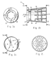
- the corresponding transverse E field pattern has a shape which resembles the TM11 mode shown in FIG. 2
- the radius at which the conductors are positioned may also be calculated using the expressions for transverse magnetic waves in a circular guide:
- the number of conductors, and the lengths of each arm of the L were chosen empirically to arrive at a configuration in which there are no variations of the distant field when the feed horn 10 is rotated. This implies that the observed far field is constant, or invariant, with respect to amplitude and phase. It appears that at least slx symmetrically disposed conductors are required to achieve a constant field when the feed horn 10 is rotated about its longitudinal axis. When four conductors were em ployed, test results indicated that there was a variation in the remote field when the feed horn 10 was rotated about its longitudinal axis.
- the long portions of the L-shaped conductors are perpendicular to the electric field of the TE11 mode. This avoids interaction with the TE11 mode except where the conductors 22 project radially. In this region the conductors 22 interact with TE11 modes to produce TEM waves which resemble a TM11 wave in the feed horn 10, and supplant it.
- the resultant transverse field distribution at the output aperture 18 resembles that produced by the TM11 mode which creates the desired radiated pattern.
- FIG. 2 shows the field distribution in cross-sectional plane, at the plane of maximum transverse fields, which is present at the output aperture of the feed horn 10.
- the locations of the ends of the conductors are disposed at a radius which is located at the center of the two nodes shown in FIG. 2.
- the conductors 22 are shown as extending to the plane of the output aperture of the feed horn 10, but this is not to imply that this is a limitation. However, the lengths of the conductors 22 may be such that they protrude from or are slightly inside the feedhorn 10. Specifically, the lengths of the conductors 22 may be adjusted in order to fine tune the radiation pattern.
- each leg of each L-shaped conductor 22 is determined to produce the necessary amplitude and phase in the radiated energy pattern.
- the position of the support member 20 along the axis is chosen to make reflections from its front and back faces cancel in the transmission band.
- the dielectric matching member 26 tunes out the remaining mismatch due to the conductors 22.
- the resulting return loss in the transmission band of 11.938 gigahertz to 12.105 gigahertz is better than 24 dB, and in the receiving band of 17.371 gigahertz to 17.705 gigahertz, the return loss is better than 18 dB.
- a compensated feed horn having the following relevant component dimension was built and tested and achieved the above-cited performance: horn length: 1.30 inches; horn wall thickness: 0.040 inches; input aperture: 0.69 inches; output aperture: 0.982 inches; compensating conductors: long arm: 0.86 inches, short arm 0.19 inches; conductor diameter: 0.05 inches; the ends of the conductors were disposed on a circle having a diameter of 0.471 inches at the output aperture; matching member: 0.125 inches thick with its aperture having an internal diameter of 0.525 inches and an external diameter at its center of 0.730 inches in diameter, tapering to match the feed horn taper; and support member thickness dimension: 0.33 inches.
Abstract
Description
- The present invention generally relates to microwave feed horns, and more particularly to a compensated microwave feed horn which reduces cross polarized components of circular polarized radiation emanating therefrom.
- State of the art twelve gigahertz antenna arrays for radar systems utilize one wavelength diameter feed horns. The diameter of such feed horns is approximately one inch. When driven at their input waveguide ports with circularly polarized energy, such feed horns generate far field radiation patterns which contain undesirable cross polarized, or opposite sense circularly polarized, components which vary in amplitude from negligible on axis to an undesirable level off axis.
- Conventional Potter-type feed horns have operating characteristics which would provide for reduced cross polarization components in off axis directions. However, the Potter-type feed horns are typically larger aperture horns and such one wavelength diameter feed horns are difficult to optimize. A better understanding of Potter-type feed horns may be found from a reading of "A New Horn Antenna with Suppressed Sidelobes and Equal Beamwidths," by P. D. Potter, Microwave Journal, Vol. VI, pages 71-78, June 1963, "The Circular Waveguide Step-Discontinuity Mode Transducer," by W. J. English, IEEE Trans. Microwave Theory Tech., Vol. MTT-21, pages 633-636, Oct. 1973, and "Phase Characteristics of a Circularly Symmetric Dual-Mode Transducer," by K. K. Agarwal, IEEE Trans. Microwave Theory Tech., Vol. MTT-18, pages 69-71, Jan. 1970.
- However, it has been found that by exciting a one inch diameter conventional feed horn with linearly polarized energy, the far field H plane and E plane radiation patterns have substantially equal magnitudes off axis at approximately 45 degrees, the axial ratio measurements using circularly polarized energy excitation indicate a phase difference off axis between E and H planes.
- In order to overcome the amplitude and phase difference problems indicated above, the present invention provides for a compensated feed horn, and more particularly, a compensator for use in an antenna feed horn, which reduces off-axis cross polarized components of circular polarized radiation emanating therefrom when it is excited with circularly polarized energy.
- The feed horn generally comprises a base having an input aperture and a conical horn portion extending from the base to an output aperture.The compensator portion comprises a plurality of L-shaped compensating conductors disposed symmetrically about a longitudinal axis of the feed horn and extending from its output aperture a predetermined distance toward the base and then radially outwards a predetermined distance away from the longitudinal axis of the feed horn toward its sidewall. The compensating conductors are disposed at a predetermined angle relative to the axis, which angle is defined by an imaginary cone whose apex is the same as the apex of the conical horn portion.
- A nonconducting support structure is attached to the feed horn and to the plurality of compensating conductors for supporting the conductors within the feed horn. A dielectric member having an aperture of predetermined size is disposed between the base and the compensating conductors for eliminating unwanted energy reflection caused by the compensating conductors and the support structure.
- The present invention substantially reduces the cross polarized component of circularly polarized energy over a wide range of directions, typically up to about forty degrees off axis. Indeed, test results show an improvement in off-axis circular polarization for single horns and for a secondary pattern for an array of feed horns illuminating a parabolic reflector.
- The various features and advantages of the present invention may be more readily understood with reference to the following detailed description taken in conjunction with the accompanying drawing, wherein like reference numerals designate like structural elements, and in which:
- FIGS. 1a-c illustrate three views of an embodiment of a compensated feed horn in accordance with the present invention; and
- FIG. 2 illustrates the correcting field distribution in cross-sectional plane which is present at the output aperture of the feed horn.
- Referring to FIGS. 1a-c, back, cutaway side and front views of a compensated
feed horn 10 in accordance with the present invention are shown. Thefeed horn 10 includes abase 12 having aninput aperture 14, and aconical horn portion 16 which tapers to anoutput aperture 18. In the disclosed embodiment, thefeed horn 10 has a circular cross section. However, the feed horn cross section may be any appropriate cross section other than circular. - A
hollow support member 20 is disposed within thefeed horn 10 and is adapted to secure and support a plurality of L-shaped compensatingconductors 22 within thefeed horn 10. Thehollow support member 20 may be any dielectric material, but is generally chosen to have low loss and a low dielectric constant. A suitable material for use in constructing thesupport member 20 is a product known as ULTEM 1000, sold by General Electric Company, although this material has a dielectric constant of about 3.1, which might not be suitable for all applications. However, the ULTEM 1000 material is suitable for high ambient temperature applications. The plurality ofconductors 22 are symmetrically arranged in a conical fashion as will be more fully discussed below. - The final component of the compensated
feed horn 10 is amatching member 26 having an aperture disposed therein which is disposed between thebase 12 and thesupport member 20. The matching member is generally a dielectric material, such as a cross linked polystyrene material, or the like, manufactured by the Polymer Corporation, sold as catalog item Q200.5, or Emerson Cummings Corporation, sold under the trade name Stycast, and generally known in the art as Rexolite. - The plurality of L-shaped compensating
conductors 22 may be comprised of metal wire, such as copper, or tin-copper, or the like, which may be plated with silver, or the like, to reduce energy loss during operation. The plurality of compensating conductors lie along an imaginary cone whose apex generally coincides with the apex of a cone that defines the sidewall of thehorn portion 16. The positions of the conductors and the cone angle were initially determined based on empirical data. The cone angle is such that its radius is chosen at a point where there are no radial components of the E field pattern for the TM₁₁ mode. The corresponding transverse E field pattern has a shape which resembles the TM₁₁ mode shown in FIG. 2 - The radius at which the conductors are positioned may also be calculated using the expressions for transverse magnetic waves in a circular guide:

- One boundary condition is satisfied where the axial E field, which is proportional to J₁(k c a),, is zero, where a is the radius of the inside of the feed horn wall. This allows a determination of the value of k c . The equation J₁(k c a) = 0 is solved for k c a, which has a root, other than at zero, at 3.832. The location of the nodes where the radial component is equal to zero where J₁′(k c r) = 0. Thus, J r ′(k c r) has a root, other than at zero, at k c r = 1.841. Therefore, the distance r at which the conductors are located from the longitudinal axis of the feed horn is determined from the ratio k c r ÷ k c a = r ÷ a = 1.841÷ 3.832 = 0.480. Therefore the desired position of the conductors at a particular point in the feed horn is 0.480 times the radius of the wall at that particular point.
- The above expressions are generally well-known in the art, by may be more readily understood with reference to the book entitled "Fields and Waves in Modern Radio," by Simon Ramo and John R. Whinnery, published by John Wiley and Sons, and in particular at pages 335-338.
- The number of conductors, and the lengths of each arm of the L were chosen empirically to arrive at a configuration in which there are no variations of the distant field when the
feed horn 10 is rotated. This implies that the observed far field is constant, or invariant, with respect to amplitude and phase. It appears that at least slx symmetrically disposed conductors are required to achieve a constant field when thefeed horn 10 is rotated about its longitudinal axis. When four conductors were em ployed, test results indicated that there was a variation in the remote field when thefeed horn 10 was rotated about its longitudinal axis. - The
conductors 22, which are coupled to its TE₁₁ waveguide mode by their radial portion, carry currents which result in a donut like remote field pattern. This field adds to the field produced by the TE₁₁ mode in thefeed horn 10 to produce the desired corrected pattern. - The long portions of the L-shaped conductors are perpendicular to the electric field of the TE₁₁ mode. This avoids interaction with the TE₁₁ mode except where the
conductors 22 project radially. In this region theconductors 22 interact with TE₁₁ modes to produce TEM waves which resemble a TM₁₁ wave in thefeed horn 10, and supplant it. The resultant transverse field distribution at theoutput aperture 18 resembles that produced by the TM₁₁ mode which creates the desired radiated pattern. Reference is made to FIG. 2 which shows the field distribution in cross-sectional plane, at the plane of maximum transverse fields, which is present at the output aperture of thefeed horn 10. The locations of the ends of the conductors are disposed at a radius which is located at the center of the two nodes shown in FIG. 2. Theconductors 22 are shown as extending to the plane of the output aperture of thefeed horn 10, but this is not to imply that this is a limitation. However, the lengths of theconductors 22 may be such that they protrude from or are slightly inside thefeedhorn 10. Specifically, the lengths of theconductors 22 may be adjusted in order to fine tune the radiation pattern. - It has been found that the azimuth radiation pattern of the
feed horn 10 using fourconductors 22 has four maxima. However, sixconductors 22 eliminate any detectable variation. The length of each leg of each L-shapedconductor 22 is determined to produce the necessary amplitude and phase in the radiated energy pattern. The position of thesupport member 20 along the axis is chosen to make reflections from its front and back faces cancel in the transmission band. Thedielectric matching member 26 tunes out the remaining mismatch due to theconductors 22. The resulting return loss in the transmission band of 11.938 gigahertz to 12.105 gigahertz is better than 24 dB, and in the receiving band of 17.371 gigahertz to 17.705 gigahertz, the return loss is better than 18 dB. - A compensated feed horn having the following relevant component dimension was built and tested and achieved the above-cited performance: horn length: 1.30 inches; horn wall thickness: 0.040 inches; input aperture: 0.69 inches; output aperture: 0.982 inches; compensating conductors: long arm: 0.86 inches, short arm 0.19 inches; conductor diameter: 0.05 inches; the ends of the conductors were disposed on a circle having a diameter of 0.471 inches at the output aperture; matching member: 0.125 inches thick with its aperture having an internal diameter of 0.525 inches and an external diameter at its center of 0.730 inches in diameter, tapering to match the feed horn taper; and support member thickness dimension: 0.33 inches.
- Thus there has been described a new and improved compensated microwave feed horn which reduces cross polarized components of circular polarized radiation emanating therefrom. It is to be understood that the above-described embodiment is merely illustrative of some of the many specific embodiments which represent applications of the principles of the present invention. Clearly, numerous and other arrangements can be readily devised by those skilled in the art without departing from the scope of the invention.
Claims (14)
a plurality of L-shaped compensating conductors disposed symmetrically about a longitudinal axis of the feed horn and extending inwardly from its output aperture a predetermined distance toward the base and then radially outwards a predetermined distance away from the axis, and disposed at a predetermined angle relative to the axis;
a nonconducting support structure attached to the feed horn and to the plurality of compensating conductors for supporting the conductors within the feed horn; and
a matching member having a circular aperture of predetermined size disposed between the base and the compensating conductors for eliminating unwanted reflections created by the compensating conductors.
a circular base comprising an input aperture having a predetermined diameter disposed therein for receiving input energy;
a conical horn portion tapering outwardly from the base to an output aperture of the feed horn;
a plurality of L-shaped compensating conductors disposed symmetrically about a longitudinal axis of the feed horn and extending inwardly from the output aperture a predetermined distance toward the base and then radially outwards a predetermined distance away from the axis toward the conical horn portion, and disposed at a predetermined angle relative to the axis, which angle is defined by an cone whose apex is the same as the apex of the feed horn;
a nonconducting support structure attached to the feed horn and the plurality of compensating conductors for supporting the conductors within the feed horn; and
a matching member having a circular aperture of predetermined size disposed therein disposed between the base and the compensating conductors for eliminating unwanted reflections created by the compensating conductors and the support structure.
a plurality of L-shaped compensating conductors disposed symmetrically about a longitudinal axis of the feed horn and extending inwardly from its output aperture a predetermined distance toward the base and then radially outwards a predetermined distance away from the axis toward the horn portion, and disposed at a predetermined angle relative to the axis, which angle is defined by an cone whose apex is the same as the apex of the conical feed horn;
a nonconducting support structure attached to the feed horn and to the plurality of compensating conductors for supporting the conductors within the feed horn; and
a dielectric member having an aperture of predetermined size disposed between the base and the compensating conductors for eliminating unwanted energy reflection created by the compensating conductors and the support structure.
a base having an input aperture disposed therein for receiving circularly polarized input energy;
a horn portion which tapers outwardly from the base to an output aperture of the feed horn;
a plurality of L-shaped compensating conductors disposed symmetrically about a longitudinal axis of the feed horn and extending inwardly from the output aperture a predetermined distance toward the base and then a predetermined distance away from the axis toward the horn portion, and disposed at a predetermined angle relative to the axis;
a nonconducting support structure attached to the feed horn and the plurality of compensating conductors for supporting the conductors within the feed horn; and
a dielectric member having an aperture of predetermined size disposed therein disposed between the base and the compensating conductors for eliminating unwanted energy reflection created by the compensating conductors and the support structure.
a plurality of compensating conductors disposed about a longitudinal axis of the feed horn and extending inwardly from its output aperture a predetermined distance toward the base and then outwards a predetermined distance away from the axis toward the horn portion, and disposed at a predetermined angle relative to the axis;
nonconducting support structure means for supporting the plurality of compensating conductors within the feed horn; and
a matching member disposed between the base and the compensating conductors for eliminating unwanted reflections created by the compensating conductors.
a base comprising an input aperture disposed therein for receiving input energy;
a horn portion tapering outwardly from the base to an output aperture of the feed horn;
a plurality of compensating conductors disposed about a longitudinal axis of the feed horn and extending inwardly from the output aperture a predetermined distance toward the base and then outwards a predetermined distance away from the axis toward the horn portion, and disposed at a predetermined angle relative to the axis;
nonconducting support structure means for supporting the conductors within the feed horn; and
a matching member disposed between the base and the compensating conductors for eliminating unwanted reflections created by the compensating conductors and the support structure.
a plurality of compensating conductors disposed about a longitudinal axis of the feed horn and extending from its output aperture toward the base and then outwards toward the horn portion, and disposed at a predetermined angle relative to the axis;
nonconducting support structure means for supporting the plurality of compensating conductors within the feed horn; and
a matching member disposed in the feed horn for eliminating unwanted reflections created in the feed horn.
a horn portion tapering outwardly from the base to an output aperture of the feed horn;
a plurality of compensating conductors disposed about a longitudinal axis of the feed horn and extending inwardly from the output aperture and then outwards toward the horn portion, and disposed at a predetermined angle relative to the axis;
nonconducting support structure means for supporting the conductors within the feed horn; and
a matching member disposed in the feed horn for eliminating unwanted reflections created in the feed horn.
Applications Claiming Priority (2)
| Application Number | Priority Date | Filing Date | Title |
|---|---|---|---|
| US07/289,881 US4890118A (en) | 1988-12-27 | 1988-12-27 | Compensated microwave feed horn |
| US289881 | 1988-12-27 |
Publications (3)
| Publication Number | Publication Date |
|---|---|
| EP0376540A2 true EP0376540A2 (en) | 1990-07-04 |
| EP0376540A3 EP0376540A3 (en) | 1990-10-10 |
| EP0376540B1 EP0376540B1 (en) | 1995-04-12 |
Family
ID=23113529
Family Applications (1)
| Application Number | Title | Priority Date | Filing Date |
|---|---|---|---|
| EP89312952A Expired - Lifetime EP0376540B1 (en) | 1988-12-27 | 1989-12-12 | Compensated microwave feed horn |
Country Status (6)
| Country | Link |
|---|---|
| US (1) | US4890118A (en) |
| EP (1) | EP0376540B1 (en) |
| JP (1) | JPH03203402A (en) |
| AU (1) | AU606303B2 (en) |
| CA (1) | CA2004726C (en) |
| DE (1) | DE68922203T2 (en) |
Families Citing this family (118)
| Publication number | Priority date | Publication date | Assignee | Title |
|---|---|---|---|---|
| US5517203A (en) * | 1994-05-11 | 1996-05-14 | Space Systems/Loral, Inc. | Dielectric resonator filter with coupling ring and antenna system formed therefrom |
| JPH0964639A (en) * | 1995-08-25 | 1997-03-07 | Uniden Corp | Diversity antenna circuit |
| JP4982252B2 (en) * | 2007-05-30 | 2012-07-25 | 寛治 大塚 | Transmission line aperture antenna device |
| US9999038B2 (en) | 2013-05-31 | 2018-06-12 | At&T Intellectual Property I, L.P. | Remote distributed antenna system |
| US9525524B2 (en) | 2013-05-31 | 2016-12-20 | At&T Intellectual Property I, L.P. | Remote distributed antenna system |
| US8897697B1 (en) | 2013-11-06 | 2014-11-25 | At&T Intellectual Property I, Lp | Millimeter-wave surface-wave communications |
| US9768833B2 (en) | 2014-09-15 | 2017-09-19 | At&T Intellectual Property I, L.P. | Method and apparatus for sensing a condition in a transmission medium of electromagnetic waves |
| US10063280B2 (en) | 2014-09-17 | 2018-08-28 | At&T Intellectual Property I, L.P. | Monitoring and mitigating conditions in a communication network |
| US9615269B2 (en) | 2014-10-02 | 2017-04-04 | At&T Intellectual Property I, L.P. | Method and apparatus that provides fault tolerance in a communication network |
| US9685992B2 (en) | 2014-10-03 | 2017-06-20 | At&T Intellectual Property I, L.P. | Circuit panel network and methods thereof |
| US9503189B2 (en) | 2014-10-10 | 2016-11-22 | At&T Intellectual Property I, L.P. | Method and apparatus for arranging communication sessions in a communication system |
| US9973299B2 (en) | 2014-10-14 | 2018-05-15 | At&T Intellectual Property I, L.P. | Method and apparatus for adjusting a mode of communication in a communication network |
| US9627768B2 (en) | 2014-10-21 | 2017-04-18 | At&T Intellectual Property I, L.P. | Guided-wave transmission device with non-fundamental mode propagation and methods for use therewith |
| US9312919B1 (en) | 2014-10-21 | 2016-04-12 | At&T Intellectual Property I, Lp | Transmission device with impairment compensation and methods for use therewith |
| US9653770B2 (en) | 2014-10-21 | 2017-05-16 | At&T Intellectual Property I, L.P. | Guided wave coupler, coupling module and methods for use therewith |
| US9780834B2 (en) | 2014-10-21 | 2017-10-03 | At&T Intellectual Property I, L.P. | Method and apparatus for transmitting electromagnetic waves |
| US9577306B2 (en) | 2014-10-21 | 2017-02-21 | At&T Intellectual Property I, L.P. | Guided-wave transmission device and methods for use therewith |
| US9769020B2 (en) | 2014-10-21 | 2017-09-19 | At&T Intellectual Property I, L.P. | Method and apparatus for responding to events affecting communications in a communication network |
| US9461706B1 (en) | 2015-07-31 | 2016-10-04 | At&T Intellectual Property I, Lp | Method and apparatus for exchanging communication signals |
| US10243784B2 (en) | 2014-11-20 | 2019-03-26 | At&T Intellectual Property I, L.P. | System for generating topology information and methods thereof |
| US9954287B2 (en) | 2014-11-20 | 2018-04-24 | At&T Intellectual Property I, L.P. | Apparatus for converting wireless signals and electromagnetic waves and methods thereof |
| US10340573B2 (en) | 2016-10-26 | 2019-07-02 | At&T Intellectual Property I, L.P. | Launcher with cylindrical coupling device and methods for use therewith |
| US10009067B2 (en) | 2014-12-04 | 2018-06-26 | At&T Intellectual Property I, L.P. | Method and apparatus for configuring a communication interface |
| US9544006B2 (en) | 2014-11-20 | 2017-01-10 | At&T Intellectual Property I, L.P. | Transmission device with mode division multiplexing and methods for use therewith |
| US9997819B2 (en) | 2015-06-09 | 2018-06-12 | At&T Intellectual Property I, L.P. | Transmission medium and method for facilitating propagation of electromagnetic waves via a core |
| US9800327B2 (en) | 2014-11-20 | 2017-10-24 | At&T Intellectual Property I, L.P. | Apparatus for controlling operations of a communication device and methods thereof |
| US9742462B2 (en) | 2014-12-04 | 2017-08-22 | At&T Intellectual Property I, L.P. | Transmission medium and communication interfaces and methods for use therewith |
| US9876570B2 (en) | 2015-02-20 | 2018-01-23 | At&T Intellectual Property I, Lp | Guided-wave transmission device with non-fundamental mode propagation and methods for use therewith |
| US9749013B2 (en) | 2015-03-17 | 2017-08-29 | At&T Intellectual Property I, L.P. | Method and apparatus for reducing attenuation of electromagnetic waves guided by a transmission medium |
| US10224981B2 (en) | 2015-04-24 | 2019-03-05 | At&T Intellectual Property I, Lp | Passive electrical coupling device and methods for use therewith |
| US9705561B2 (en) | 2015-04-24 | 2017-07-11 | At&T Intellectual Property I, L.P. | Directional coupling device and methods for use therewith |
| US9793954B2 (en) | 2015-04-28 | 2017-10-17 | At&T Intellectual Property I, L.P. | Magnetic coupling device and methods for use therewith |
| US9871282B2 (en) | 2015-05-14 | 2018-01-16 | At&T Intellectual Property I, L.P. | At least one transmission medium having a dielectric surface that is covered at least in part by a second dielectric |
| US9490869B1 (en) | 2015-05-14 | 2016-11-08 | At&T Intellectual Property I, L.P. | Transmission medium having multiple cores and methods for use therewith |
| US9748626B2 (en) | 2015-05-14 | 2017-08-29 | At&T Intellectual Property I, L.P. | Plurality of cables having different cross-sectional shapes which are bundled together to form a transmission medium |
| US10650940B2 (en) | 2015-05-15 | 2020-05-12 | At&T Intellectual Property I, L.P. | Transmission medium having a conductive material and methods for use therewith |
| US9917341B2 (en) | 2015-05-27 | 2018-03-13 | At&T Intellectual Property I, L.P. | Apparatus and method for launching electromagnetic waves and for modifying radial dimensions of the propagating electromagnetic waves |
| US10812174B2 (en) | 2015-06-03 | 2020-10-20 | At&T Intellectual Property I, L.P. | Client node device and methods for use therewith |
| US9912381B2 (en) | 2015-06-03 | 2018-03-06 | At&T Intellectual Property I, Lp | Network termination and methods for use therewith |
| US9866309B2 (en) | 2015-06-03 | 2018-01-09 | At&T Intellectual Property I, Lp | Host node device and methods for use therewith |
| US9913139B2 (en) | 2015-06-09 | 2018-03-06 | At&T Intellectual Property I, L.P. | Signal fingerprinting for authentication of communicating devices |
| US9820146B2 (en) | 2015-06-12 | 2017-11-14 | At&T Intellectual Property I, L.P. | Method and apparatus for authentication and identity management of communicating devices |
| US9509415B1 (en) | 2015-06-25 | 2016-11-29 | At&T Intellectual Property I, L.P. | Methods and apparatus for inducing a fundamental wave mode on a transmission medium |
| US9640850B2 (en) | 2015-06-25 | 2017-05-02 | At&T Intellectual Property I, L.P. | Methods and apparatus for inducing a non-fundamental wave mode on a transmission medium |
| US9865911B2 (en) | 2015-06-25 | 2018-01-09 | At&T Intellectual Property I, L.P. | Waveguide system for slot radiating first electromagnetic waves that are combined into a non-fundamental wave mode second electromagnetic wave on a transmission medium |
| US9628116B2 (en) | 2015-07-14 | 2017-04-18 | At&T Intellectual Property I, L.P. | Apparatus and methods for transmitting wireless signals |
| US9882257B2 (en) | 2015-07-14 | 2018-01-30 | At&T Intellectual Property I, L.P. | Method and apparatus for launching a wave mode that mitigates interference |
| US9847566B2 (en) | 2015-07-14 | 2017-12-19 | At&T Intellectual Property I, L.P. | Method and apparatus for adjusting a field of a signal to mitigate interference |
| US10205655B2 (en) | 2015-07-14 | 2019-02-12 | At&T Intellectual Property I, L.P. | Apparatus and methods for communicating utilizing an antenna array and multiple communication paths |
| US10148016B2 (en) | 2015-07-14 | 2018-12-04 | At&T Intellectual Property I, L.P. | Apparatus and methods for communicating utilizing an antenna array |
| US10044409B2 (en) | 2015-07-14 | 2018-08-07 | At&T Intellectual Property I, L.P. | Transmission medium and methods for use therewith |
| US9853342B2 (en) | 2015-07-14 | 2017-12-26 | At&T Intellectual Property I, L.P. | Dielectric transmission medium connector and methods for use therewith |
| US10090606B2 (en) | 2015-07-15 | 2018-10-02 | At&T Intellectual Property I, L.P. | Antenna system with dielectric array and methods for use therewith |
| US9912027B2 (en) | 2015-07-23 | 2018-03-06 | At&T Intellectual Property I, L.P. | Method and apparatus for exchanging communication signals |
| US9749053B2 (en) | 2015-07-23 | 2017-08-29 | At&T Intellectual Property I, L.P. | Node device, repeater and methods for use therewith |
| US9871283B2 (en) | 2015-07-23 | 2018-01-16 | At&T Intellectual Property I, Lp | Transmission medium having a dielectric core comprised of plural members connected by a ball and socket configuration |
| US9948333B2 (en) | 2015-07-23 | 2018-04-17 | At&T Intellectual Property I, L.P. | Method and apparatus for wireless communications to mitigate interference |
| US9967173B2 (en) | 2015-07-31 | 2018-05-08 | At&T Intellectual Property I, L.P. | Method and apparatus for authentication and identity management of communicating devices |
| US9735833B2 (en) | 2015-07-31 | 2017-08-15 | At&T Intellectual Property I, L.P. | Method and apparatus for communications management in a neighborhood network |
| US9904535B2 (en) | 2015-09-14 | 2018-02-27 | At&T Intellectual Property I, L.P. | Method and apparatus for distributing software |
| US9769128B2 (en) | 2015-09-28 | 2017-09-19 | At&T Intellectual Property I, L.P. | Method and apparatus for encryption of communications over a network |
| US9729197B2 (en) | 2015-10-01 | 2017-08-08 | At&T Intellectual Property I, L.P. | Method and apparatus for communicating network management traffic over a network |
| US9876264B2 (en) | 2015-10-02 | 2018-01-23 | At&T Intellectual Property I, Lp | Communication system, guided wave switch and methods for use therewith |
| US10355367B2 (en) | 2015-10-16 | 2019-07-16 | At&T Intellectual Property I, L.P. | Antenna structure for exchanging wireless signals |
| US9860075B1 (en) | 2016-08-26 | 2018-01-02 | At&T Intellectual Property I, L.P. | Method and communication node for broadband distribution |
| US10811767B2 (en) | 2016-10-21 | 2020-10-20 | At&T Intellectual Property I, L.P. | System and dielectric antenna with convex dielectric radome |
| US10312567B2 (en) | 2016-10-26 | 2019-06-04 | At&T Intellectual Property I, L.P. | Launcher with planar strip antenna and methods for use therewith |
| US10498044B2 (en) | 2016-11-03 | 2019-12-03 | At&T Intellectual Property I, L.P. | Apparatus for configuring a surface of an antenna |
| US10291334B2 (en) | 2016-11-03 | 2019-05-14 | At&T Intellectual Property I, L.P. | System for detecting a fault in a communication system |
| US10225025B2 (en) | 2016-11-03 | 2019-03-05 | At&T Intellectual Property I, L.P. | Method and apparatus for detecting a fault in a communication system |
| US10224634B2 (en) | 2016-11-03 | 2019-03-05 | At&T Intellectual Property I, L.P. | Methods and apparatus for adjusting an operational characteristic of an antenna |
| US10340601B2 (en) | 2016-11-23 | 2019-07-02 | At&T Intellectual Property I, L.P. | Multi-antenna system and methods for use therewith |
| US10090594B2 (en) | 2016-11-23 | 2018-10-02 | At&T Intellectual Property I, L.P. | Antenna system having structural configurations for assembly |
| US10340603B2 (en) | 2016-11-23 | 2019-07-02 | At&T Intellectual Property I, L.P. | Antenna system having shielded structural configurations for assembly |
| US10535928B2 (en) | 2016-11-23 | 2020-01-14 | At&T Intellectual Property I, L.P. | Antenna system and methods for use therewith |
| US10178445B2 (en) | 2016-11-23 | 2019-01-08 | At&T Intellectual Property I, L.P. | Methods, devices, and systems for load balancing between a plurality of waveguides |
| US10361489B2 (en) | 2016-12-01 | 2019-07-23 | At&T Intellectual Property I, L.P. | Dielectric dish antenna system and methods for use therewith |
| US10305190B2 (en) | 2016-12-01 | 2019-05-28 | At&T Intellectual Property I, L.P. | Reflecting dielectric antenna system and methods for use therewith |
| US10439675B2 (en) | 2016-12-06 | 2019-10-08 | At&T Intellectual Property I, L.P. | Method and apparatus for repeating guided wave communication signals |
| US10135145B2 (en) | 2016-12-06 | 2018-11-20 | At&T Intellectual Property I, L.P. | Apparatus and methods for generating an electromagnetic wave along a transmission medium |
| US10755542B2 (en) | 2016-12-06 | 2020-08-25 | At&T Intellectual Property I, L.P. | Method and apparatus for surveillance via guided wave communication |
| US10020844B2 (en) | 2016-12-06 | 2018-07-10 | T&T Intellectual Property I, L.P. | Method and apparatus for broadcast communication via guided waves |
| US9927517B1 (en) | 2016-12-06 | 2018-03-27 | At&T Intellectual Property I, L.P. | Apparatus and methods for sensing rainfall |
| US10819035B2 (en) | 2016-12-06 | 2020-10-27 | At&T Intellectual Property I, L.P. | Launcher with helical antenna and methods for use therewith |
| US10326494B2 (en) | 2016-12-06 | 2019-06-18 | At&T Intellectual Property I, L.P. | Apparatus for measurement de-embedding and methods for use therewith |
| US10694379B2 (en) | 2016-12-06 | 2020-06-23 | At&T Intellectual Property I, L.P. | Waveguide system with device-based authentication and methods for use therewith |
| US10727599B2 (en) | 2016-12-06 | 2020-07-28 | At&T Intellectual Property I, L.P. | Launcher with slot antenna and methods for use therewith |
| US10637149B2 (en) | 2016-12-06 | 2020-04-28 | At&T Intellectual Property I, L.P. | Injection molded dielectric antenna and methods for use therewith |
| US10382976B2 (en) | 2016-12-06 | 2019-08-13 | At&T Intellectual Property I, L.P. | Method and apparatus for managing wireless communications based on communication paths and network device positions |
| US10168695B2 (en) | 2016-12-07 | 2019-01-01 | At&T Intellectual Property I, L.P. | Method and apparatus for controlling an unmanned aircraft |
| US10139820B2 (en) | 2016-12-07 | 2018-11-27 | At&T Intellectual Property I, L.P. | Method and apparatus for deploying equipment of a communication system |
| US10027397B2 (en) | 2016-12-07 | 2018-07-17 | At&T Intellectual Property I, L.P. | Distributed antenna system and methods for use therewith |
| US9893795B1 (en) | 2016-12-07 | 2018-02-13 | At&T Intellectual Property I, Lp | Method and repeater for broadband distribution |
| US10446936B2 (en) | 2016-12-07 | 2019-10-15 | At&T Intellectual Property I, L.P. | Multi-feed dielectric antenna system and methods for use therewith |
| US10547348B2 (en) | 2016-12-07 | 2020-01-28 | At&T Intellectual Property I, L.P. | Method and apparatus for switching transmission mediums in a communication system |
| US10359749B2 (en) | 2016-12-07 | 2019-07-23 | At&T Intellectual Property I, L.P. | Method and apparatus for utilities management via guided wave communication |
| US10389029B2 (en) | 2016-12-07 | 2019-08-20 | At&T Intellectual Property I, L.P. | Multi-feed dielectric antenna system with core selection and methods for use therewith |
| US10243270B2 (en) | 2016-12-07 | 2019-03-26 | At&T Intellectual Property I, L.P. | Beam adaptive multi-feed dielectric antenna system and methods for use therewith |
| US9911020B1 (en) | 2016-12-08 | 2018-03-06 | At&T Intellectual Property I, L.P. | Method and apparatus for tracking via a radio frequency identification device |
| US10916969B2 (en) | 2016-12-08 | 2021-02-09 | At&T Intellectual Property I, L.P. | Method and apparatus for providing power using an inductive coupling |
| US10326689B2 (en) | 2016-12-08 | 2019-06-18 | At&T Intellectual Property I, L.P. | Method and system for providing alternative communication paths |
| US10601494B2 (en) | 2016-12-08 | 2020-03-24 | At&T Intellectual Property I, L.P. | Dual-band communication device and method for use therewith |
| US10777873B2 (en) | 2016-12-08 | 2020-09-15 | At&T Intellectual Property I, L.P. | Method and apparatus for mounting network devices |
| US10069535B2 (en) | 2016-12-08 | 2018-09-04 | At&T Intellectual Property I, L.P. | Apparatus and methods for launching electromagnetic waves having a certain electric field structure |
| US10411356B2 (en) | 2016-12-08 | 2019-09-10 | At&T Intellectual Property I, L.P. | Apparatus and methods for selectively targeting communication devices with an antenna array |
| US10530505B2 (en) | 2016-12-08 | 2020-01-07 | At&T Intellectual Property I, L.P. | Apparatus and methods for launching electromagnetic waves along a transmission medium |
| US9998870B1 (en) | 2016-12-08 | 2018-06-12 | At&T Intellectual Property I, L.P. | Method and apparatus for proximity sensing |
| US10938108B2 (en) | 2016-12-08 | 2021-03-02 | At&T Intellectual Property I, L.P. | Frequency selective multi-feed dielectric antenna system and methods for use therewith |
| US10389037B2 (en) | 2016-12-08 | 2019-08-20 | At&T Intellectual Property I, L.P. | Apparatus and methods for selecting sections of an antenna array and use therewith |
| US10103422B2 (en) | 2016-12-08 | 2018-10-16 | At&T Intellectual Property I, L.P. | Method and apparatus for mounting network devices |
| US10340983B2 (en) | 2016-12-09 | 2019-07-02 | At&T Intellectual Property I, L.P. | Method and apparatus for surveying remote sites via guided wave communications |
| US9838896B1 (en) | 2016-12-09 | 2017-12-05 | At&T Intellectual Property I, L.P. | Method and apparatus for assessing network coverage |
| US10264586B2 (en) | 2016-12-09 | 2019-04-16 | At&T Mobility Ii Llc | Cloud-based packet controller and methods for use therewith |
| US9973940B1 (en) | 2017-02-27 | 2018-05-15 | At&T Intellectual Property I, L.P. | Apparatus and methods for dynamic impedance matching of a guided wave launcher |
| US10298293B2 (en) | 2017-03-13 | 2019-05-21 | At&T Intellectual Property I, L.P. | Apparatus of communication utilizing wireless network devices |
| US11070250B2 (en) | 2019-12-03 | 2021-07-20 | At&T Intellectual Property I, L.P. | Method and apparatus for calibrating waveguide systems to manage propagation delays of electromagnetic waves |
| US11502724B2 (en) | 2019-12-03 | 2022-11-15 | At&T Intellectual Property I, L.P. | Method and apparatus for transitioning between electromagnetic wave modes |
| US11277159B2 (en) | 2019-12-03 | 2022-03-15 | At&T Intellectual Property I, L.P. | Method and apparatus for managing propagation delays of electromagnetic waves |
Citations (4)
| Publication number | Priority date | Publication date | Assignee | Title |
|---|---|---|---|---|
| GB1099378A (en) * | 1965-04-29 | 1968-01-17 | Marconi Co Ltd | Improvements in or relating to radio horns |
| US3573838A (en) * | 1968-10-28 | 1971-04-06 | Hughes Aircraft Co | Broadband multimode horn antenna |
| US4114121A (en) * | 1976-01-16 | 1978-09-12 | National Research Development Corporation | Apparatus and methods for launching and screening electromagnetic waves in the dipole mode |
| FR2400779A1 (en) * | 1977-08-17 | 1979-03-16 | Spinner Gmbh Elektrotech | TRANSMISSION SYSTEM |
Family Cites Families (5)
| Publication number | Priority date | Publication date | Assignee | Title |
|---|---|---|---|---|
| JPS4914375A (en) * | 1972-06-02 | 1974-02-07 | ||
| JPS5368542A (en) * | 1976-11-30 | 1978-06-19 | Mitsubishi Electric Corp | Horn antenna |
| JPS5368539A (en) * | 1976-11-30 | 1978-06-19 | Mitsubishi Electric Corp | Horn antenna |
| JPS5368536A (en) * | 1976-11-30 | 1978-06-19 | Mitsubishi Electric Corp | Horn antenna |
| US4712110A (en) * | 1985-12-26 | 1987-12-08 | General Dynamics, Pomona Division | Five-port monopulse antenna feed structure with one dedicated transmit port |
-
1988
- 1988-12-27 US US07/289,881 patent/US4890118A/en not_active Expired - Fee Related
-
1989
- 1989-12-06 CA CA002004726A patent/CA2004726C/en not_active Expired - Fee Related
- 1989-12-12 DE DE68922203T patent/DE68922203T2/en not_active Expired - Fee Related
- 1989-12-12 EP EP89312952A patent/EP0376540B1/en not_active Expired - Lifetime
- 1989-12-21 AU AU47059/89A patent/AU606303B2/en not_active Ceased
- 1989-12-27 JP JP1345113A patent/JPH03203402A/en active Pending
Patent Citations (4)
| Publication number | Priority date | Publication date | Assignee | Title |
|---|---|---|---|---|
| GB1099378A (en) * | 1965-04-29 | 1968-01-17 | Marconi Co Ltd | Improvements in or relating to radio horns |
| US3573838A (en) * | 1968-10-28 | 1971-04-06 | Hughes Aircraft Co | Broadband multimode horn antenna |
| US4114121A (en) * | 1976-01-16 | 1978-09-12 | National Research Development Corporation | Apparatus and methods for launching and screening electromagnetic waves in the dipole mode |
| FR2400779A1 (en) * | 1977-08-17 | 1979-03-16 | Spinner Gmbh Elektrotech | TRANSMISSION SYSTEM |
Also Published As
| Publication number | Publication date |
|---|---|
| CA2004726A1 (en) | 1990-06-27 |
| JPH03203402A (en) | 1991-09-05 |
| EP0376540B1 (en) | 1995-04-12 |
| US4890118A (en) | 1989-12-26 |
| EP0376540A3 (en) | 1990-10-10 |
| AU606303B2 (en) | 1991-01-31 |
| AU4705989A (en) | 1990-07-05 |
| DE68922203D1 (en) | 1995-05-18 |
| DE68922203T2 (en) | 1995-11-09 |
| CA2004726C (en) | 1994-08-02 |
Similar Documents
| Publication | Publication Date | Title |
|---|---|---|
| US4890118A (en) | Compensated microwave feed horn | |
| US5126750A (en) | Magnetic hybrid-mode horn antenna | |
| US3568204A (en) | Multimode antenna feed system having a plurality of tracking elements mounted symmetrically about the inner walls and at the aperture end of a scalar horn | |
| Kildal | The hat feed: A dual-mode rear-radiating waveguide antenna having low cross polarization | |
| US6011520A (en) | Geodesic slotted cylindrical antenna | |
| KR0148253B1 (en) | Embedded surface wave antenna | |
| Thomas et al. | Design of wide-band corrugated conical horns for Cassegrain antennas | |
| US3713167A (en) | Omni-steerable cardioid antenna | |
| WO1986005327A1 (en) | Hybrid mode horn antennas | |
| US3032762A (en) | Circularly arrayed slot antenna | |
| EP1127383A1 (en) | Coaxial cavity antenna | |
| US3500419A (en) | Dual frequency,dual polarized cassegrain antenna | |
| US4199764A (en) | Dual band combiner for horn antenna | |
| US3268902A (en) | Dual frequency microwave aperturetype antenna providing similar radiation pattern on both frequencies | |
| CN114520418A (en) | Dual polarized horn antenna with asymmetric radiation pattern | |
| US3576579A (en) | Planar radial array with controllable quasi-optical lens | |
| EP0357085B1 (en) | A coaxial-waveguide phase shifter | |
| US4890117A (en) | Antenna and waveguide mode converter | |
| US3364489A (en) | Traveling wave antenna having radiator elements with doubly periodic spacing | |
| US4040061A (en) | Broadband corrugated horn antenna | |
| US6222492B1 (en) | Dual coaxial feed for tracking antenna | |
| US2895134A (en) | Directional antenna systems | |
| JPH0522016A (en) | Low side lobe reflection mirror antenna and horn antenna | |
| US2727233A (en) | Dielectric rod antenna | |
| Lee | A compact QK-band dual frequency feed horn |
Legal Events
| Date | Code | Title | Description |
|---|---|---|---|
| PUAI | Public reference made under article 153(3) epc to a published international application that has entered the european phase |
Free format text: ORIGINAL CODE: 0009012 |
|
| AK | Designated contracting states |
Kind code of ref document: A2 Designated state(s): DE FR GB IT |
|
| PUAL | Search report despatched |
Free format text: ORIGINAL CODE: 0009013 |
|
| AK | Designated contracting states |
Kind code of ref document: A3 Designated state(s): DE FR GB IT |
|
| 17P | Request for examination filed |
Effective date: 19910318 |
|
| 17Q | First examination report despatched |
Effective date: 19930705 |
|
| GRAA | (expected) grant |
Free format text: ORIGINAL CODE: 0009210 |
|
| AK | Designated contracting states |
Kind code of ref document: B1 Designated state(s): DE FR GB IT |
|
| REF | Corresponds to: |
Ref document number: 68922203 Country of ref document: DE Date of ref document: 19950518 |
|
| ITF | It: translation for a ep patent filed |
Owner name: SOCIETA' ITALIANA BREVETTI S.P.A. |
|
| ET | Fr: translation filed | ||
| PG25 | Lapsed in a contracting state [announced via postgrant information from national office to epo] |
Ref country code: GB Effective date: 19951212 |
|
| PLBE | No opposition filed within time limit |
Free format text: ORIGINAL CODE: 0009261 |
|
| STAA | Information on the status of an ep patent application or granted ep patent |
Free format text: STATUS: NO OPPOSITION FILED WITHIN TIME LIMIT |
|
| 26N | No opposition filed | ||
| GBPC | Gb: european patent ceased through non-payment of renewal fee |
Effective date: 19951212 |
|
| PG25 | Lapsed in a contracting state [announced via postgrant information from national office to epo] |
Ref country code: FR Effective date: 19960830 |
|
| PG25 | Lapsed in a contracting state [announced via postgrant information from national office to epo] |
Ref country code: DE Effective date: 19960903 |
|
| REG | Reference to a national code |
Ref country code: FR Ref legal event code: ST |
|
| PG25 | Lapsed in a contracting state [announced via postgrant information from national office to epo] |
Ref country code: IT Free format text: LAPSE BECAUSE OF NON-PAYMENT OF DUE FEES;WARNING: LAPSES OF ITALIAN PATENTS WITH EFFECTIVE DATE BEFORE 2007 MAY HAVE OCCURRED AT ANY TIME BEFORE 2007. THE CORRECT EFFECTIVE DATE MAY BE DIFFERENT FROM THE ONE RECORDED. Effective date: 20051212 |