EP0372824B1 - Led array polarized image source/0 degree hologram virtual image head up display - Google Patents
Led array polarized image source/0 degree hologram virtual image head up display Download PDFInfo
- Publication number
- EP0372824B1 EP0372824B1 EP89312457A EP89312457A EP0372824B1 EP 0372824 B1 EP0372824 B1 EP 0372824B1 EP 89312457 A EP89312457 A EP 89312457A EP 89312457 A EP89312457 A EP 89312457A EP 0372824 B1 EP0372824 B1 EP 0372824B1
- Authority
- EP
- European Patent Office
- Prior art keywords
- hologram
- image source
- virtual image
- light beam
- display system
- Prior art date
- Legal status (The legal status is an assumption and is not a legal conclusion. Google has not performed a legal analysis and makes no representation as to the accuracy of the status listed.)
- Expired - Lifetime
Links
Images

Classifications
-
- G—PHYSICS
- G02—OPTICS
- G02B—OPTICAL ELEMENTS, SYSTEMS OR APPARATUS
- G02B27/00—Optical systems or apparatus not provided for by any of the groups G02B1/00 - G02B26/00, G02B30/00
- G02B27/10—Beam splitting or combining systems
- G02B27/1086—Beam splitting or combining systems operating by diffraction only
- G02B27/1093—Beam splitting or combining systems operating by diffraction only for use with monochromatic radiation only, e.g. devices for splitting a single laser source
-
- G—PHYSICS
- G02—OPTICS
- G02B—OPTICAL ELEMENTS, SYSTEMS OR APPARATUS
- G02B27/00—Optical systems or apparatus not provided for by any of the groups G02B1/00 - G02B26/00, G02B30/00
- G02B27/01—Head-up displays
- G02B27/0101—Head-up displays characterised by optical features
- G02B27/0103—Head-up displays characterised by optical features comprising holographic elements
-
- G—PHYSICS
- G02—OPTICS
- G02B—OPTICAL ELEMENTS, SYSTEMS OR APPARATUS
- G02B27/00—Optical systems or apparatus not provided for by any of the groups G02B1/00 - G02B26/00, G02B30/00
- G02B27/01—Head-up displays
- G02B27/0101—Head-up displays characterised by optical features
- G02B2027/0118—Head-up displays characterised by optical features comprising devices for improving the contrast of the display / brillance control visibility
- G02B2027/012—Head-up displays characterised by optical features comprising devices for improving the contrast of the display / brillance control visibility comprising devices for attenuating parasitic image effects
-
- G—PHYSICS
- G02—OPTICS
- G02B—OPTICAL ELEMENTS, SYSTEMS OR APPARATUS
- G02B5/00—Optical elements other than lenses
- G02B5/30—Polarising elements
Definitions
- the disclosed invention is directed generally to a head-up holographic virtual image display, and is more particularly directed to a dynamic holographic virtual image instrument display for a vehicle.
- Head-up holographic instrument displays for vehicles which provide virtual images that appear to be located ahead of the vehicle windshield toward the front of the vehicle, provide the advantages of increased safety since the operator does not have to significantly divert attention from viewing the outside, and are more readily noticed in the event of the display warning of a malfunction.
- Known head-up displays displays include "static" displays wherein predetermined message holograms (e.g., "low fuel”) in a vehicle windshield are selectively illuminated by appropriate light sources.
- predetermined message holograms e.g., "low fuel”
- the obvious problem with such static displays is their inability to indicate changing parameters such as vehicle speed or engine speed.
- Known head-up displays also include "dynamic" displays wherein the visible image is changeable.
- An example is the use of individual hologram segments in a vehicle windshield which are selectively illuminated by respective beams to control the visibility of the individual segments to display changing numerical information, for example.
- the use of hologram segments provides low image resolution, and is subject to ambient scatter and ambient turn-on (i.e., the unintended "turn-on" of the hologram image caused by an ambient light source). Ambient turn-on is a particularly important consideration since erroneous readings will occur, which could be potentially dangerous depending on the displayed information.
- the illuminating light sources would have to be carefully aligned and maintained in alignment, this dynamic display is complex, expensive, and subject to potential reliability problems.
- EP-A-0216692 discloses a system in which a hologram in a vehicle windscreen acts as a plane mirror with selected wavelength reflection tuned to the wavelength of the display source.
- a carrier layer supports the hologram and is curved to match the windscreen.
- the carrier layer may be sandwiched inside laminations of the windscreen or attached directly to the inside face of the windscreen.
- a virtual image display system comprising: a dynamic image source comprising means for providing light beams emanating therefrom; and a hologram positioned to reflect the light beam emanating from the image source to produce an observable virtual image of the image source, characterised in that: the means for providing a light beam provides a light beam having a narrow spectral bandwidth of less than about 50 nanometers; the image source comprises a polarizer to provide P-polarization of the light beam emanating from the image source, and the hologram comprises a non-slanted mirror reflection hologram.
- a head-up dynamic holographic display system that includes a dynamic image source 20 and a mirror reflection hologram 11.
- the holographic display system can be installed in an automobile as illustrated in FIG. 1.
- the image source 20 would be on the dashboard or in a recess in the dashboard, while the mirror reflection hologram 11 would be laminated between the inside and outside glass layers of the windshield.
- FIG. 2 shown therein is an exploded view of the dynamic image source 20 which includes an apertured mask 13 having openings that define the symbols or characters that are to be displayed.
- the mask 13 is shown as having segment shaped openings 15 which can define three digits utilized to indicate vehicle speed (i.e., a digital speedometer).
- the image source 20 further includes a polarizer 17 beneath the mask 13 for providing P-polarization of the illumination provided by LEDs 19 which are below the polarizer 17 and provide dynamically changing illumination when selectively activated.
- the LEDs 19 are supported by a circuit board 21, for example, which includes appropriate drive circuitry (not shown) for the LEDs 19.
- the LEDs 19 are arranged to illuminate the openings 15 in the mask 13.
- the lenses of LEDs 19 are shaped so that LEDs for a given segmented opening 15 can be located close to each other to provide the appearance of being a continuous source of light.
- two closely fitted LEDs are provided for each of the segmented openings 15.
- the shaping of the LED lenses can be achieved by custom manufacture or by appropriately cutting the lenses of commercially available LEDs. Selective activation of the LEDs, for example to indicate vehicle speed, provides a dynamic image to the mirror reflection hologram 11.
- the LEDs 19 advantageously provide narrow cones of narrow spectral bandwidth illumination, preferably less than about 50 nanometers, without filtering and the attendant attenuation. Since the illumination is spectrally narrowband, the reflection mirror hologram 11 can also be narrowband since its bandwidth needs to be only as wide as that of the pertinent illumination. With a narrowband reflection mirror hologram, light from outside the vehicle is not significantly reflected, and substantial background darkening and tinting (which would occur with a wideband image source and a wideband hologram) are avoided.
- the illumination cone provided by each of the LEDs is preferably sufficiently narrow to be substantially confined within an appropriately sized eyebox region at the viewing optical distance.
- appropriate spherical or aspherical optical elements can be utilized to shape the beams provided by the LEDs 19, to control the size of the virtual image, to control the location of the virtual image relative to the driver, and/or to substantially confine the illumination within an appropriately sized eyebox region.
- the illumination provided by the LEDs 19 should be sufficiently bright to provide clear visibility under the expected brightest conditions, for example bright sunlight.
- the illumination cone, bandwidth, and brightness characteristics can be provided by custom manufacture of the LEDs 19 or by appropriate selection of commercially available LEDs.
- the commercially available Stanley H-3000 LED could be utilized.
- This LED provides light over about a 9.7 degree full-width angular circular cone, and has a spectral bandwidth of 25 nanometers (nm).
- the 9.7 degree cone of light advantageously produces an eyebox having a diameter of about 6 inches when viewed at a typical optical distance of about 36 inches.
- the Stanley H-1000 has similar illumination cone and spectral characteristics, but provides less illumination for any given voltage and costs less. In some applications, the reduced illumination may be satisfactory since the necessary brightness is dictated by visibility in bright sunlight.
- a high gain diffuser 22 can optionally be located between the LEDs 19 and the polarizer 17 to broaden the eyebox if necessary and/or to improve image uniformity.
- Possible high gain screens include Polacoat 15 gain screens marketed by the Da-Lite Screen Company (Cincinnati, Ohio), high gain lenticular screens marketed by Protolite (Palo Alto, California), finely ground glass, frosty Scotch brand tape, or an electrically controlled variable scatter liquid crystal layer. Use of two spatially separated high gain screens yields further improvement in image uniformity.
- light control film marketed by the 3M Company can be located between the mask 13 and the polarizer 17, which allows only light within a narrow angular range to pass through, and helps prevent ambient light from reflecting off the diffuser.
- the image source 20 is configured so that the front portion comprising the mask 13, the polarizer 17, and the diffuser 22 is tilted so that it is not normal to emanating light.
- the front face of the image source 20 would be tilted clockwise; i.e., with the forward edge tilted upward.
- the LEDs are aligned to provide illumination in the vertical direction
- the front face of the image source 20 would be tilted to be non- horizontal.
- the top of the resulting virtual image would appear to be tilted away from the driver.
- the reflection hologram 11 is a high diffraction efficiency, non-slanted fringe (0 degree), narrowband reflection mirror hologram tuned to be reflective over the appropriate spectral bandwidth and incident angle of the image source 20.
- the hologram would be tuned to be reflective over a nominal full width spectral bandwidth of 25 nanometers centered at 660 nanometers for light incident at a particular off-axis angle (i.e., at some angle relative to normal).
- the fringes of the hologram are unslanted with respect to the surface for the following reasons.
- the non-slanted fringe hologram avoids certain problems discussed above, it introduces the problem of a double ghost image that results from the reflections off the outside and inside glass/air interfaces being in the same direction as the hologram reflection.
- the P-polarizer 17 which provides polarization parallel to the plane of incidence, reduces the ghost imaging. This results from the fact that although the reflection at a glass/air interface at high incident angles such as 67 degrees is high for S-polarized light, it is very low for P-polarized light, dropping to zero percent at the Brewster angle, which is about 56° incident angle for a glass/air interface.
- the hologram peak efficiency and spectral bandwidth at high incident angles such as 67° is much less for P-polarized light than for S-polarized light.
- a bandwidth of 30 nanometers and 95 percent peak efficiency at 660 nanometers and 67° incident angle can be achieved for P-polarized light.
- S-polarized light the corresponding spectral bandwidth would be about 70 nanometers. While this results in some see-through discoloration, it would not be objectionable since the peak wavelength is deep in the red portion of the visible spectrum.
- the viewer operator will probably reduce the main image brightness down to be about 50 percent as bright as the background ambient brightness.
- the ghost image from the front glass/air interface would only be 1 percent of the ambient brightness, which will render it unobjectionable and probably unnoticeable.
- one layer of a windshield is only typically 70-90 mils thick, the ghost image will be only slightly displaced relative to the primary image, which reduces the noticeability of the ghost image.
- the foregoing described hologram 11 includes characteristics which allow it to be advantageously utilized in automobiles. With peak reflectance at a wavelength of 660 nm at a 67 degree incident angles, the peak reflectance at normal is at a wavelength of 803 nm, which will pass present federal transmittance requirements. Since the hologram is mounted within the windshield, the federal windshield abrasion requirements are met. Glare reflecting off the windshield does not present a problems, since the hologram has a high peak wavelength, is narrowband, and is a small patch only that does not cover the entire windshield. As a result of mounting the hologram within the windshield, see-through distortion is minimal and the hologram edges are not readily noticeable.
- the hologram 11 is immune to ambient turn-on and ambient scatter which occur with image holograms. Further, under severe viewing conditions when road glare is present, the display is highly viewable. Road glare is predominately S-polarized, and polarized sunglasses are typically designed to block S-polarized light. Therefore, the P-polarized light from the display passed through polarized sunglasses unimpeded, with improved image to background contrast.
- optical assembly which would provide a virtual image located further ahead of the windshield (i.e., further away from the driver).
- the optical assembly includes a housing 115 to which the image source 20 is secured.
- a fold mirror 111 secured in the housing reflects the illumination from the image source to a spherical mirror 113, also secured in the housing 115, which in turn relays the illumination through a transparent cover 117 to the reflection mirror hologram within the windshield.
- a head-up holographic display for vehicles such as automobiles which provides advantages including a dynamically changing, bright, uniform, sharp, flare-free virtual image behind a windshield with high photopic see-through, immunity to ambient turn-on and scatter, minimal see-through discoloration, minimal ghosting, minimal see-through distortion, minimal dashboard glare, minimal hologram edge visibility, and compatibility with polarized sunglasses.
- the components of the display system permit efficient production at low cost.
- the use of small, efficient and low cost LEDs provides for a compact, low cost, energy efficient, narrow beam image source which does not utilize filtering to achieve a narrow bandwidth of less than about 50 nm.
- the zero degree hologram is amenable to low cost production such as laser scanning, and no critical alignment is required.
Description
- The disclosed invention is directed generally to a head-up holographic virtual image display, and is more particularly directed to a dynamic holographic virtual image instrument display for a vehicle.
- Head-up holographic instrument displays for vehicles, which provide virtual images that appear to be located ahead of the vehicle windshield toward the front of the vehicle, provide the advantages of increased safety since the operator does not have to significantly divert attention from viewing the outside, and are more readily noticed in the event of the display warning of a malfunction.
- Known head-up displays displays include "static" displays wherein predetermined message holograms (e.g., "low fuel") in a vehicle windshield are selectively illuminated by appropriate light sources. The obvious problem with such static displays is their inability to indicate changing parameters such as vehicle speed or engine speed.
- Known head-up displays also include "dynamic" displays wherein the visible image is changeable. An example is the use of individual hologram segments in a vehicle windshield which are selectively illuminated by respective beams to control the visibility of the individual segments to display changing numerical information, for example. However, the use of hologram segments provides low image resolution, and is subject to ambient scatter and ambient turn-on (i.e., the unintended "turn-on" of the hologram image caused by an ambient light source). Ambient turn-on is a particularly important consideration since erroneous readings will occur, which could be potentially dangerous depending on the displayed information. Further, since the illuminating light sources would have to be carefully aligned and maintained in alignment, this dynamic display is complex, expensive, and subject to potential reliability problems.
- EP-A-0216692 discloses a system in which a hologram in a vehicle windscreen acts as a plane mirror with selected wavelength reflection tuned to the wavelength of the display source. A carrier layer supports the hologram and is curved to match the windscreen. The carrier layer may be sandwiched inside laminations of the windscreen or attached directly to the inside face of the windscreen.
- According to the invention there is provided a virtual image display system comprising: a dynamic image source comprising means for providing light beams emanating therefrom; and a hologram positioned to reflect the light beam emanating from the image source to produce an observable virtual image of the image source, characterised in that: the means for providing a light beam provides a light beam having a narrow spectral bandwidth of less than about 50 nanometers; the image source comprises a polarizer to provide P-polarization of the light beam emanating from the image source, and the hologram comprises a non-slanted mirror reflection hologram.
- The advantages and features of the disclosed invention will readily be appreciated by persons skilled in the art from the following detailed description when read in conjunction with the drawings wherein:
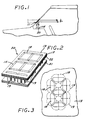
- FIG. 1 is a schematic illustration of the major components of the disclosed head-up holographic display system.
- FIG. 2 is a schematic exploded view of the image source of the holographic display system of FIG. 1.
- FIG. 3 is detail view showing the configuration of the LED light sources of the image source of FIG. 2.
- FIG. 4 is a schematic exploded view of an optical system that can be used with the disclosed head-up holographic display system for controlling the size and location of the virtual image.
- In the following detailed description and in the several figures of the drawing, like elements are identified with like reference numerals.
- Referring now to FIG. 1, shown therein is a head-up dynamic holographic display system that includes a
dynamic image source 20 and a mirror reflection hologram 11. By way of example, the holographic display system can be installed in an automobile as illustrated in FIG. 1. Theimage source 20 would be on the dashboard or in a recess in the dashboard, while the mirror reflection hologram 11 would be laminated between the inside and outside glass layers of the windshield. - Referring now to FIG. 2, shown therein is an exploded view of the
dynamic image source 20 which includes anapertured mask 13 having openings that define the symbols or characters that are to be displayed. By way of specific example, themask 13 is shown as having segment shapedopenings 15 which can define three digits utilized to indicate vehicle speed (i.e., a digital speedometer). - The
image source 20 further includes apolarizer 17 beneath themask 13 for providing P-polarization of the illumination provided byLEDs 19 which are below thepolarizer 17 and provide dynamically changing illumination when selectively activated. TheLEDs 19 are supported by acircuit board 21, for example, which includes appropriate drive circuitry (not shown) for theLEDs 19. - As shown schematically in FIG. 3, the
LEDs 19 are arranged to illuminate theopenings 15 in themask 13. The lenses ofLEDs 19 are shaped so that LEDs for a givensegmented opening 15 can be located close to each other to provide the appearance of being a continuous source of light. For example, two closely fitted LEDs are provided for each of the segmentedopenings 15. The shaping of the LED lenses can be achieved by custom manufacture or by appropriately cutting the lenses of commercially available LEDs. Selective activation of the LEDs, for example to indicate vehicle speed, provides a dynamic image to the mirror reflection hologram 11. - The
LEDs 19 advantageously provide narrow cones of narrow spectral bandwidth illumination, preferably less than about 50 nanometers, without filtering and the attendant attenuation. Since the illumination is spectrally narrowband, the reflection mirror hologram 11 can also be narrowband since its bandwidth needs to be only as wide as that of the pertinent illumination. With a narrowband reflection mirror hologram, light from outside the vehicle is not significantly reflected, and substantial background darkening and tinting (which would occur with a wideband image source and a wideband hologram) are avoided. - For efficiency and image brightness, the illumination cone provided by each of the LEDs is preferably sufficiently narrow to be substantially confined within an appropriately sized eyebox region at the viewing optical distance. As illustrated in FIG. 4, discussed further herein, appropriate spherical or aspherical optical elements can be utilized to shape the beams provided by the
LEDs 19, to control the size of the virtual image, to control the location of the virtual image relative to the driver, and/or to substantially confine the illumination within an appropriately sized eyebox region. - The illumination provided by the
LEDs 19 should be sufficiently bright to provide clear visibility under the expected brightest conditions, for example bright sunlight. The illumination cone, bandwidth, and brightness characteristics can be provided by custom manufacture of theLEDs 19 or by appropriate selection of commercially available LEDs. - By way of specific example, the commercially available Stanley H-3000 LED could be utilized. This LED provides light over about a 9.7 degree full-width angular circular cone, and has a spectral bandwidth of 25 nanometers (nm). The 9.7 degree cone of light advantageously produces an eyebox having a diameter of about 6 inches when viewed at a typical optical distance of about 36 inches.
- The Stanley H-1000 has similar illumination cone and spectral characteristics, but provides less illumination for any given voltage and costs less. In some applications, the reduced illumination may be satisfactory since the necessary brightness is dictated by visibility in bright sunlight.
- A
high gain diffuser 22 can optionally be located between theLEDs 19 and thepolarizer 17 to broaden the eyebox if necessary and/or to improve image uniformity. Possible high gain screens include Polacoat 15 gain screens marketed by the Da-Lite Screen Company (Cincinnati, Ohio), high gain lenticular screens marketed by Protolite (Palo Alto, California), finely ground glass, frosty Scotch brand tape, or an electrically controlled variable scatter liquid crystal layer. Use of two spatially separated high gain screens yields further improvement in image uniformity. - For further image enhancement of an
image source 20 that includes adiffuser 22, light control film marketed by the 3M Company can be located between themask 13 and thepolarizer 17, which allows only light within a narrow angular range to pass through, and helps prevent ambient light from reflecting off the diffuser. - Preferably, to avoid potentially dazzling reflections, the
image source 20 is configured so that the front portion comprising themask 13, thepolarizer 17, and thediffuser 22 is tilted so that it is not normal to emanating light. Specifically as viewed in FIG. 1, the front face of theimage source 20 would be tilted clockwise; i.e., with the forward edge tilted upward. By way of specific example, if the LEDs are aligned to provide illumination in the vertical direction, the front face of theimage source 20 would be tilted to be non- horizontal. The top of the resulting virtual image would appear to be tilted away from the driver. - The reflection hologram 11 is a high diffraction efficiency, non-slanted fringe (0 degree), narrowband reflection mirror hologram tuned to be reflective over the appropriate spectral bandwidth and incident angle of the
image source 20. For example, for the previously identified H-3000 LED, the hologram would be tuned to be reflective over a nominal full width spectral bandwidth of 25 nanometers centered at 660 nanometers for light incident at a particular off-axis angle (i.e., at some angle relative to normal). The fringes of the hologram are unslanted with respect to the surface for the following reasons. Blurring of the image due to chromatic dispersion is avoided as is the problem of hologram flare, which is the transmissive diffraction inherent in all slant-fringe holograms that produces objectionable rainbows in the field of view from light sources such as on-coming headlights. - While the non-slanted fringe hologram avoids certain problems discussed above, it introduces the problem of a double ghost image that results from the reflections off the outside and inside glass/air interfaces being in the same direction as the hologram reflection. The P-
polarizer 17, which provides polarization parallel to the plane of incidence, reduces the ghost imaging. This results from the fact that although the reflection at a glass/air interface at high incident angles such as 67 degrees is high for S-polarized light, it is very low for P-polarized light, dropping to zero percent at the Brewster angle, which is about 56° incident angle for a glass/air interface. - There are, however, transmittance considerations with tuning the bandwidth of the hologram 11 to the bandwidth of the P-polarized illumination. The hologram peak efficiency and spectral bandwidth at high incident angles such as 67° is much less for P-polarized light than for S-polarized light. For example, with dichromated gelatin volume holograms, a bandwidth of 30 nanometers and 95 percent peak efficiency at 660 nanometers and 67° incident angle can be achieved for P-polarized light. For S-polarized light the corresponding spectral bandwidth would be about 70 nanometers. While this results in some see-through discoloration, it would not be objectionable since the peak wavelength is deep in the red portion of the visible spectrum. With that efficiency and bandwidth, most of the LED light having the characteristics of the Stanley LEDs discussed above will be reflected. Of the small amount that leaks through, only 2-3 percent will get reflected off the outside glass/air interface toward the viewer and of this amount, 95 percent will be reflected by the hologram. Therefore, if the hologram is efficient and of sufficient bandwidth, the ghost image from the outside glass/air interface will be substantially eliminated. The ghost image from the inside glass/air interface should only be about 2-3 percent the brightness of the hologram reflection.
- In use, the viewer operator will probably reduce the main image brightness down to be about 50 percent as bright as the background ambient brightness. In that case, the ghost image from the front glass/air interface would only be 1 percent of the ambient brightness, which will render it unobjectionable and probably unnoticeable. Further, since one layer of a windshield is only typically 70-90 mils thick, the ghost image will be only slightly displaced relative to the primary image, which reduces the noticeability of the ghost image.
- The foregoing described hologram 11 includes characteristics which allow it to be advantageously utilized in automobiles. With peak reflectance at a wavelength of 660 nm at a 67 degree incident angles, the peak reflectance at normal is at a wavelength of 803 nm, which will pass present federal transmittance requirements. Since the hologram is mounted within the windshield, the federal windshield abrasion requirements are met. Glare reflecting off the windshield does not present a problems, since the hologram has a high peak wavelength, is narrowband, and is a small patch only that does not cover the entire windshield. As a result of mounting the hologram within the windshield, see-through distortion is minimal and the hologram edges are not readily noticeable. Also, the hologram 11 is immune to ambient turn-on and ambient scatter which occur with image holograms. Further, under severe viewing conditions when road glare is present, the display is highly viewable. Road glare is predominately S-polarized, and polarized sunglasses are typically designed to block S-polarized light. Therefore, the P-polarized light from the display passed through polarized sunglasses unimpeded, with improved image to background contrast.
- As mentioned previously, appropriate spherical or aspherical optical elements (e.g., lenses or mirrors) could be used to shape the beams provided by the LEDs, to control image size, and/or to control location of the virtual image relative to the driver. Referring now to FIG. 4, shown therein is an optical assembly which would provide a virtual image located further ahead of the windshield (i.e., further away from the driver). The optical assembly includes a housing 115 to which the
image source 20 is secured. A fold mirror 111 secured in the housing reflects the illumination from the image source to aspherical mirror 113, also secured in the housing 115, which in turn relays the illumination through a transparent cover 117 to the reflection mirror hologram within the windshield. - It should be appreciated that presently known head-up displays that utilize spectrally broad vacuum-fluorescent tubes as image sources can be readily modified to utilize the reflection mirror hologram and the narrowband, narrow beam LED image source described above.
- The foregoing has been a disclosure of a head-up holographic display for vehicles such as automobiles which provides advantages including a dynamically changing, bright, uniform, sharp, flare-free virtual image behind a windshield with high photopic see-through, immunity to ambient turn-on and scatter, minimal see-through discoloration, minimal ghosting, minimal see-through distortion, minimal dashboard glare, minimal hologram edge visibility, and compatibility with polarized sunglasses. Further, the components of the display system permit efficient production at low cost. The use of small, efficient and low cost LEDs provides for a compact, low cost, energy efficient, narrow beam image source which does not utilize filtering to achieve a narrow bandwidth of less than about 50 nm. The zero degree hologram is amenable to low cost production such as laser scanning, and no critical alignment is required.
- Although the foregoing has been a description and illustration of specific embodiments of the invention, various modifications and changes thereto can be made by persons skilled in the art without departing from the scope of the invention as defined by the following claims.
Claims (6)
- A virtual image display system comprising:
a dynamic image source (20) comprising means (19) for providing a light beam emanating therefrom; and
a hologram (11) positioned to reflect the light beam emanating from the image source (20) to produce an observable virtual image of the image source (20); characterised in that:
the means for providing a light beam (19) provides a light beam having a narrow spectral bandwidth of less than about 50 nanometers;
the image source (20) comprises a polarizer (17) to provide P-polarization relative to the plane of incidence on the hologram of the light beam emanating from the image source (20); and
the hologram (11) comprises a non-slanted mirror reflection hologram. - A virtual image display system according to claim 1 wherein said means for providing a light beam comprises light emitting diodes (19).
- A virtual image display system according to claim 1 or 2 wherein the dynamic image source (20) comprises an apertured mask (13) having openings that define the symbols or characters that are to be displayed.
- A virtual image display system according to claim 1, 2 or 3 wherein the dynamic image source (20) further comprises a diffuser (22) located between the means for providing a light beam and the polarizer (17).
- A virtual image display system according to any preceding claim wherein the system further comprises spherical or aspherical optical elements to shape the said light beam from the image source (20), to control the size of the virtual image and/or to control the location of the virtual image.
- A virtual image display system according to any preceding claim wherein the non-slanted mirror reflection hologram (11) is tuned to the P-polarization spectral bandwidth of the light beam emanating from the image source (20).
Applications Claiming Priority (2)
| Application Number | Priority Date | Filing Date | Title |
|---|---|---|---|
| US278083 | 1988-11-30 | ||
| US07/278,083 US5044709A (en) | 1988-11-30 | 1988-11-30 | LED array polarized image source/0 degree hologram virtual image head up display |
Publications (3)
| Publication Number | Publication Date |
|---|---|
| EP0372824A2 EP0372824A2 (en) | 1990-06-13 |
| EP0372824A3 EP0372824A3 (en) | 1990-11-28 |
| EP0372824B1 true EP0372824B1 (en) | 1994-04-27 |
Family
ID=23063612
Family Applications (1)
| Application Number | Title | Priority Date | Filing Date |
|---|---|---|---|
| EP89312457A Expired - Lifetime EP0372824B1 (en) | 1988-11-30 | 1989-11-30 | Led array polarized image source/0 degree hologram virtual image head up display |
Country Status (7)
| Country | Link |
|---|---|
| US (1) | US5044709A (en) |
| EP (1) | EP0372824B1 (en) |
| JP (1) | JPH0685027B2 (en) |
| CA (1) | CA2001971C (en) |
| DE (1) | DE68914957T2 (en) |
| ES (1) | ES2051374T3 (en) |
| IL (1) | IL92273A (en) |
Families Citing this family (39)
| Publication number | Priority date | Publication date | Assignee | Title |
|---|---|---|---|---|
| DE3822222A1 (en) * | 1988-07-01 | 1990-01-04 | Bosch Gmbh Robert | DEVICE FOR HEAD-UP DISPLAYS ON MOTOR VEHICLES |
| JP2653186B2 (en) * | 1989-09-27 | 1997-09-10 | キヤノン株式会社 | Head-up display device |
| US5214425A (en) * | 1991-05-30 | 1993-05-25 | Hughes Aircraft Company | Superimposed tell-tales |
| US5469298A (en) * | 1991-08-14 | 1995-11-21 | Prince Corporation | Reflective display at infinity |
| DE4319904C2 (en) * | 1993-06-16 | 2002-11-28 | Siemens Ag | Warning device for displaying information in a vehicle |
| US5486840A (en) * | 1994-03-21 | 1996-01-23 | Delco Electronics Corporation | Head up display with incident light filter |
| US5878395A (en) * | 1995-12-08 | 1999-03-02 | Intermec Ip Corp. | Code reading terminal with integrated vehicular head-up display capability |
| ATE209364T1 (en) | 1996-03-15 | 2001-12-15 | Retinal Display Cayman Ltd | METHOD AND DEVICE FOR VIEWING AN IMAGE |
| US6204974B1 (en) | 1996-10-08 | 2001-03-20 | The Microoptical Corporation | Compact image display system for eyeglasses or other head-borne frames |
| US5886822A (en) * | 1996-10-08 | 1999-03-23 | The Microoptical Corporation | Image combining system for eyeglasses and face masks |
| US6023372A (en) * | 1997-10-30 | 2000-02-08 | The Microoptical Corporation | Light weight, compact remountable electronic display device for eyeglasses or other head-borne eyewear frames |
| EP1027627B1 (en) * | 1997-10-30 | 2009-02-11 | MYVU Corporation | Eyeglass interface system |
| WO2000007066A1 (en) | 1998-07-29 | 2000-02-10 | Digilens, Inc. | In-line infinity display system employing one or more switchable holographic optical elements |
| EP1114340A1 (en) * | 1998-09-14 | 2001-07-11 | Digilens Inc. | Holographic illumination system and holographic projection system |
| AU1209100A (en) | 1998-10-16 | 2000-05-08 | Digilens Inc. | Holographic technique for illumination of image displays using ambient illumination |
| AU6519099A (en) | 1998-10-16 | 2000-05-08 | Digilens Inc. | Method and system for display resolution multiplication |
| US6094283A (en) * | 1998-10-16 | 2000-07-25 | Digilens, Inc. | Holographic display with switchable aspect ratio |
| US6115151A (en) * | 1998-12-30 | 2000-09-05 | Digilens, Inc. | Method for producing a multi-layer holographic device |
| US6678078B1 (en) | 1999-01-07 | 2004-01-13 | Digilens, Inc. | Optical filter employing holographic optical elements and image generating system incorporating the optical filter |
| KR20010090432A (en) | 1999-03-23 | 2001-10-18 | 추후 보정 | Illumination system using optical feedback |
| US6504629B1 (en) | 1999-03-23 | 2003-01-07 | Digilens, Inc. | Method and apparatus for illuminating a display |
| US6724354B1 (en) | 1999-06-21 | 2004-04-20 | The Microoptical Corporation | Illumination systems for eyeglass and facemask display systems |
| DE60006535T2 (en) | 1999-06-21 | 2004-09-23 | The Microoptical Corp., Westwood | DISPLAY DEVICE WITH OKULAR, DISPLAY AND LIGHTING DEVICE ON OPTOMECHANICAL CARRIER |
| US7158096B1 (en) | 1999-06-21 | 2007-01-02 | The Microoptical Corporation | Compact, head-mountable display device with suspended eyepiece assembly |
| US6353503B1 (en) | 1999-06-21 | 2002-03-05 | The Micropitical Corporation | Eyeglass display lens system employing off-axis optical design |
| AU6400300A (en) | 1999-08-04 | 2001-03-05 | Digilens Inc. | Apparatus for producing a three-dimensional image |
| US6323970B1 (en) | 1999-09-29 | 2001-11-27 | Digilents, Inc. | Method of producing switchable holograms |
| TW528169U (en) * | 2000-05-04 | 2003-04-11 | Koninkl Philips Electronics Nv | Assembly of a display device and an illumination system |
| US6417970B1 (en) * | 2000-06-08 | 2002-07-09 | Interactive Imaging Systems | Two stage optical system for head mounted display |
| US6424437B1 (en) | 2000-10-10 | 2002-07-23 | Digilens, Inc. | Projection display employing switchable holographic optical elements |
| US7313246B2 (en) | 2001-10-06 | 2007-12-25 | Stryker Corporation | Information system using eyewear for communication |
| CA2473549C (en) * | 2002-01-16 | 2011-02-15 | Japan Science And Technology Agency | Moving-image holographic reproducing device and color moving-image holographic reproducing device |
| US7031067B2 (en) * | 2004-03-10 | 2006-04-18 | Motorola, Inc. | Head-up display |
| KR100705796B1 (en) * | 2005-11-09 | 2007-04-12 | 전자부품연구원 | Head up display system using light emitting diode |
| US20070103545A1 (en) * | 2005-11-09 | 2007-05-10 | Digital Video Media, L.L.C. | 360 Degree display |
| JP2012063524A (en) * | 2010-09-15 | 2012-03-29 | Nippon Seiki Co Ltd | Vehicular head-up display device |
| FR2995410B1 (en) * | 2012-09-13 | 2014-08-29 | Renault Sa | DISPLAY DEVICE FOR MOTOR VEHICLE |
| JP6340807B2 (en) * | 2014-02-05 | 2018-06-13 | 株式会社リコー | Image display device and moving body |
| JP6300738B2 (en) * | 2015-01-20 | 2018-03-28 | カルソニックカンセイ株式会社 | Head-up display device |
Family Cites Families (14)
| Publication number | Priority date | Publication date | Assignee | Title |
|---|---|---|---|---|
| US3915548A (en) * | 1973-04-30 | 1975-10-28 | Hughes Aircraft Co | Holographic lens and liquid crystal image source for head-up display |
| JPS52147092A (en) * | 1976-06-01 | 1977-12-07 | Citizen Watch Co Ltd | Structure of display device |
| US4412719A (en) * | 1981-04-10 | 1983-11-01 | Environmental Research Institute Of Michigan | Method and article having predetermined net reflectance characteristics |
| US4372639A (en) * | 1981-06-03 | 1983-02-08 | Hughes Aircraft Company | Directional diffusing screen |
| GB2143948B (en) * | 1983-07-23 | 1986-08-06 | Ferranti Plc | Apparatus for determining the direction of a line of sight |
| US4815800A (en) * | 1984-12-21 | 1989-03-28 | Hughes Aircraft Company | Flare reduction in holograms |
| US4688879A (en) * | 1985-07-08 | 1987-08-25 | Kaiser Optical Systems, Inc. | Holographic multi-combiner for head-up display |
| DE3532120A1 (en) * | 1985-09-10 | 1987-03-19 | Ver Glaswerke Gmbh | WINDSHIELD WITH A REFLECTIVE DEVICE FOR MIRRORING OPTICAL SIGNALS INTO THE FIELD OF THE DRIVER |
| US4789977A (en) * | 1986-11-06 | 1988-12-06 | Laser Magnetic Storage International Company | Optical data recording device |
| US4795223A (en) * | 1987-01-06 | 1989-01-03 | Hughes Aircraft Company | Segmented 3-D hologram display |
| US4790613A (en) * | 1987-01-06 | 1988-12-13 | Hughes Aircraft Company | Holographic display panel for a vehicle windshield |
| JP2556020B2 (en) * | 1987-02-06 | 1996-11-20 | 日本電装株式会社 | Display device using hologram |
| US4761056A (en) * | 1987-03-27 | 1988-08-02 | Kaiser Aerospace And Electronics Corporation | Compact helmet mounted display |
| US4958892A (en) * | 1988-10-18 | 1990-09-25 | Physical Optics Corporation | Diffraction coherence filter |
-
1988
- 1988-11-30 US US07/278,083 patent/US5044709A/en not_active Expired - Fee Related
-
1989
- 1989-11-01 CA CA002001971A patent/CA2001971C/en not_active Expired - Fee Related
- 1989-11-10 IL IL9227389A patent/IL92273A/en not_active IP Right Cessation
- 1989-11-30 DE DE68914957T patent/DE68914957T2/en not_active Expired - Fee Related
- 1989-11-30 JP JP1312205A patent/JPH0685027B2/en not_active Expired - Lifetime
- 1989-11-30 ES ES89312457T patent/ES2051374T3/en not_active Expired - Lifetime
- 1989-11-30 EP EP89312457A patent/EP0372824B1/en not_active Expired - Lifetime
Non-Patent Citations (1)
| Title |
|---|
| PHYSICS OF SEMICONDUCTOR DEVICES, 2nd Ed., by S.M. Sze, John Wiley & Sons, 1989, page 681. * |
Also Published As
| Publication number | Publication date |
|---|---|
| EP0372824A2 (en) | 1990-06-13 |
| IL92273A (en) | 1995-07-31 |
| DE68914957D1 (en) | 1994-06-01 |
| DE68914957T2 (en) | 1994-08-11 |
| ES2051374T3 (en) | 1994-06-16 |
| EP0372824A3 (en) | 1990-11-28 |
| JPH02201313A (en) | 1990-08-09 |
| CA2001971A1 (en) | 1990-05-31 |
| JPH0685027B2 (en) | 1994-10-26 |
| US5044709A (en) | 1991-09-03 |
| CA2001971C (en) | 1995-08-01 |
Similar Documents
| Publication | Publication Date | Title |
|---|---|---|
| EP0372824B1 (en) | Led array polarized image source/0 degree hologram virtual image head up display | |
| US5440428A (en) | Automotive instrument 3-D virtual image display | |
| US6359737B1 (en) | Combined head-up display | |
| EP0398346B1 (en) | Automotive head-up display with high brightness in daytime and high contrast in nighttime | |
| EP0332693B1 (en) | Automotive instrument virtual image display | |
| EP0391231B1 (en) | Automotive head-up display | |
| US5144459A (en) | Windshield reflector for imaging signals into view of driver | |
| JP3034889B2 (en) | Head-up display | |
| US5198936A (en) | Reflective cluster display | |
| CA2026744C (en) | Polarized holographic heads up display | |
| US5212471A (en) | Polarized heads up display | |
| US5138470A (en) | Guard holograms | |
| KR930006446B1 (en) | Polarized head up display | |
| JP2568339B2 (en) | Head-up display device | |
| JPH05229366A (en) | Head-up display device | |
| Evans et al. | Head-up displays in motor cars | |
| JP2000238551A (en) | Headup display device | |
| JPH08327939A (en) | Head up display |
Legal Events
| Date | Code | Title | Description |
|---|---|---|---|
| PUAI | Public reference made under article 153(3) epc to a published international application that has entered the european phase |
Free format text: ORIGINAL CODE: 0009012 |
|
| AK | Designated contracting states |
Kind code of ref document: A2 Designated state(s): DE ES FR GB IT NL SE |
|
| PUAL | Search report despatched |
Free format text: ORIGINAL CODE: 0009013 |
|
| AK | Designated contracting states |
Kind code of ref document: A3 Designated state(s): DE ES FR GB IT NL SE |
|
| 17P | Request for examination filed |
Effective date: 19901221 |
|
| 17Q | First examination report despatched |
Effective date: 19921204 |
|
| GRAA | (expected) grant |
Free format text: ORIGINAL CODE: 0009210 |
|
| AK | Designated contracting states |
Kind code of ref document: B1 Designated state(s): DE ES FR GB IT NL SE |
|
| REF | Corresponds to: |
Ref document number: 68914957 Country of ref document: DE Date of ref document: 19940601 |
|
| REG | Reference to a national code |
Ref country code: ES Ref legal event code: FG2A Ref document number: 2051374 Country of ref document: ES Kind code of ref document: T3 |
|
| ET | Fr: translation filed | ||
| ITF | It: translation for a ep patent filed |
Owner name: SOCIETA' ITALIANA BREVETTI S.P.A. |
|
| EAL | Se: european patent in force in sweden |
Ref document number: 89312457.8 |
|
| PLBE | No opposition filed within time limit |
Free format text: ORIGINAL CODE: 0009261 |
|
| STAA | Information on the status of an ep patent application or granted ep patent |
Free format text: STATUS: NO OPPOSITION FILED WITHIN TIME LIMIT |
|
| 26N | No opposition filed | ||
| PGFP | Annual fee paid to national office [announced via postgrant information from national office to epo] |
Ref country code: FR Payment date: 19961010 Year of fee payment: 8 |
|
| PGFP | Annual fee paid to national office [announced via postgrant information from national office to epo] |
Ref country code: SE Payment date: 19961018 Year of fee payment: 8 |
|
| PGFP | Annual fee paid to national office [announced via postgrant information from national office to epo] |
Ref country code: GB Payment date: 19961022 Year of fee payment: 8 |
|
| PGFP | Annual fee paid to national office [announced via postgrant information from national office to epo] |
Ref country code: NL Payment date: 19961024 Year of fee payment: 8 Ref country code: DE Payment date: 19961024 Year of fee payment: 8 |
|
| PGFP | Annual fee paid to national office [announced via postgrant information from national office to epo] |
Ref country code: ES Payment date: 19961111 Year of fee payment: 8 |
|
| PG25 | Lapsed in a contracting state [announced via postgrant information from national office to epo] |
Ref country code: GB Free format text: LAPSE BECAUSE OF NON-PAYMENT OF DUE FEES Effective date: 19971130 Ref country code: FR Free format text: THE PATENT HAS BEEN ANNULLED BY A DECISION OF A NATIONAL AUTHORITY Effective date: 19971130 |
|
| PG25 | Lapsed in a contracting state [announced via postgrant information from national office to epo] |
Ref country code: SE Free format text: LAPSE BECAUSE OF NON-PAYMENT OF DUE FEES Effective date: 19971201 Ref country code: ES Free format text: LAPSE BECAUSE OF NON-PAYMENT OF DUE FEES Effective date: 19971201 |
|
| PG25 | Lapsed in a contracting state [announced via postgrant information from national office to epo] |
Ref country code: NL Free format text: LAPSE BECAUSE OF NON-PAYMENT OF DUE FEES Effective date: 19980601 |
|
| GBPC | Gb: european patent ceased through non-payment of renewal fee |
Effective date: 19971130 |
|
| PG25 | Lapsed in a contracting state [announced via postgrant information from national office to epo] |
Ref country code: DE Free format text: LAPSE BECAUSE OF NON-PAYMENT OF DUE FEES Effective date: 19980801 |
|
| NLV4 | Nl: lapsed or anulled due to non-payment of the annual fee |
Effective date: 19980601 |
|
| EUG | Se: european patent has lapsed |
Ref document number: 89312457.8 |
|
| REG | Reference to a national code |
Ref country code: FR Ref legal event code: ST |
|
| REG | Reference to a national code |
Ref country code: ES Ref legal event code: FD2A Effective date: 19981212 |
|
| PG25 | Lapsed in a contracting state [announced via postgrant information from national office to epo] |
Ref country code: IT Free format text: LAPSE BECAUSE OF NON-PAYMENT OF DUE FEES;WARNING: LAPSES OF ITALIAN PATENTS WITH EFFECTIVE DATE BEFORE 2007 MAY HAVE OCCURRED AT ANY TIME BEFORE 2007. THE CORRECT EFFECTIVE DATE MAY BE DIFFERENT FROM THE ONE RECORDED. Effective date: 20051130 |