EP0369712A2 - Fluid flow control - Google Patents
Fluid flow control Download PDFInfo
- Publication number
- EP0369712A2 EP0369712A2 EP89311727A EP89311727A EP0369712A2 EP 0369712 A2 EP0369712 A2 EP 0369712A2 EP 89311727 A EP89311727 A EP 89311727A EP 89311727 A EP89311727 A EP 89311727A EP 0369712 A2 EP0369712 A2 EP 0369712A2
- Authority
- EP
- European Patent Office
- Prior art keywords
- flow
- fluid
- valve
- channel
- effluent
- Prior art date
- Legal status (The legal status is an assumption and is not a legal conclusion. Google has not performed a legal analysis and makes no representation as to the accuracy of the status listed.)
- Granted
Links
Images


Classifications
-
- F—MECHANICAL ENGINEERING; LIGHTING; HEATING; WEAPONS; BLASTING
- F16—ENGINEERING ELEMENTS AND UNITS; GENERAL MEASURES FOR PRODUCING AND MAINTAINING EFFECTIVE FUNCTIONING OF MACHINES OR INSTALLATIONS; THERMAL INSULATION IN GENERAL
- F16K—VALVES; TAPS; COCKS; ACTUATING-FLOATS; DEVICES FOR VENTING OR AERATING
- F16K31/00—Actuating devices; Operating means; Releasing devices
- F16K31/44—Mechanical actuating means
- F16K31/52—Mechanical actuating means with crank, eccentric, or cam
- F16K31/524—Mechanical actuating means with crank, eccentric, or cam with a cam
- F16K31/52408—Mechanical actuating means with crank, eccentric, or cam with a cam comprising a lift valve
- F16K31/52416—Mechanical actuating means with crank, eccentric, or cam with a cam comprising a lift valve comprising a multiple-way lift valve
-
- A—HUMAN NECESSITIES
- A61—MEDICAL OR VETERINARY SCIENCE; HYGIENE
- A61M—DEVICES FOR INTRODUCING MEDIA INTO, OR ONTO, THE BODY; DEVICES FOR TRANSDUCING BODY MEDIA OR FOR TAKING MEDIA FROM THE BODY; DEVICES FOR PRODUCING OR ENDING SLEEP OR STUPOR
- A61M5/00—Devices for bringing media into the body in a subcutaneous, intra-vascular or intramuscular way; Accessories therefor, e.g. filling or cleaning devices, arm-rests
- A61M5/14—Infusion devices, e.g. infusing by gravity; Blood infusion; Accessories therefor
- A61M5/168—Means for controlling media flow to the body or for metering media to the body, e.g. drip meters, counters ; Monitoring media flow to the body
- A61M5/16877—Adjusting flow; Devices for setting a flow rate
- A61M5/16881—Regulating valves
-
- A—HUMAN NECESSITIES
- A61—MEDICAL OR VETERINARY SCIENCE; HYGIENE
- A61M—DEVICES FOR INTRODUCING MEDIA INTO, OR ONTO, THE BODY; DEVICES FOR TRANSDUCING BODY MEDIA OR FOR TAKING MEDIA FROM THE BODY; DEVICES FOR PRODUCING OR ENDING SLEEP OR STUPOR
- A61M2205/00—General characteristics of the apparatus
- A61M2205/02—General characteristics of the apparatus characterised by a particular materials
- A61M2205/0244—Micromachined materials, e.g. made from silicon wafers, microelectromechanical systems [MEMS] or comprising nanotechnology
-
- A—HUMAN NECESSITIES
- A61—MEDICAL OR VETERINARY SCIENCE; HYGIENE
- A61M—DEVICES FOR INTRODUCING MEDIA INTO, OR ONTO, THE BODY; DEVICES FOR TRANSDUCING BODY MEDIA OR FOR TAKING MEDIA FROM THE BODY; DEVICES FOR PRODUCING OR ENDING SLEEP OR STUPOR
- A61M5/00—Devices for bringing media into the body in a subcutaneous, intra-vascular or intramuscular way; Accessories therefor, e.g. filling or cleaning devices, arm-rests
- A61M5/14—Infusion devices, e.g. infusing by gravity; Blood infusion; Accessories therefor
- A61M5/141—Infusion devices, e.g. infusing by gravity; Blood infusion; Accessories therefor with capillaries for restricting fluid flow
-
- Y—GENERAL TAGGING OF NEW TECHNOLOGICAL DEVELOPMENTS; GENERAL TAGGING OF CROSS-SECTIONAL TECHNOLOGIES SPANNING OVER SEVERAL SECTIONS OF THE IPC; TECHNICAL SUBJECTS COVERED BY FORMER USPC CROSS-REFERENCE ART COLLECTIONS [XRACs] AND DIGESTS
- Y10—TECHNICAL SUBJECTS COVERED BY FORMER USPC
- Y10T—TECHNICAL SUBJECTS COVERED BY FORMER US CLASSIFICATION
- Y10T137/00—Fluid handling
- Y10T137/8593—Systems
- Y10T137/85938—Non-valved flow dividers
-
- Y—GENERAL TAGGING OF NEW TECHNOLOGICAL DEVELOPMENTS; GENERAL TAGGING OF CROSS-SECTIONAL TECHNOLOGIES SPANNING OVER SEVERAL SECTIONS OF THE IPC; TECHNICAL SUBJECTS COVERED BY FORMER USPC CROSS-REFERENCE ART COLLECTIONS [XRACs] AND DIGESTS
- Y10—TECHNICAL SUBJECTS COVERED BY FORMER USPC
- Y10T—TECHNICAL SUBJECTS COVERED BY FORMER US CLASSIFICATION
- Y10T137/00—Fluid handling
- Y10T137/8593—Systems
- Y10T137/87056—With selective motion for plural valve actuator
- Y10T137/87064—Oppositely movable cam surfaces
-
- Y—GENERAL TAGGING OF NEW TECHNOLOGICAL DEVELOPMENTS; GENERAL TAGGING OF CROSS-SECTIONAL TECHNOLOGIES SPANNING OVER SEVERAL SECTIONS OF THE IPC; TECHNICAL SUBJECTS COVERED BY FORMER USPC CROSS-REFERENCE ART COLLECTIONS [XRACs] AND DIGESTS
- Y10—TECHNICAL SUBJECTS COVERED BY FORMER USPC
- Y10T—TECHNICAL SUBJECTS COVERED BY FORMER US CLASSIFICATION
- Y10T137/00—Fluid handling
- Y10T137/8593—Systems
- Y10T137/87265—Dividing into parallel flow paths with recombining
- Y10T137/87298—Having digital flow controller
- Y10T137/87306—Having plural branches under common control for separate valve actuators
Definitions
- the present invention relates to medical infusion devices, and, more particularly, to variable flow rate regulators for accurately regulating the effluent flow from a source of pressurized fluid.
- Intravenous or other parenteral administration of fluids is routinely performed in hospitals, other medical facilities, and emergency sites in the field.
- infusion of normal saline or lactated Ringer's solution to achieve normovolemia during surgery or following trauma is typically accomplished at a relatively high flow rate.
- administration of certain antiarrythmics such as Lidocaine or Procanamide following myocardial infarction may desirably be accomplished at any of a variety of relatively slow rates.
- antineoplastic agents must be performed at a very slow and constant rate over a prolonged period to avoid localized necrosis at the infusion site.
- IV administration of antibiotics is desirable in some circumstances, at relatively slow delivery rates such as 50 cc over 90 minutes or more. Not only do a large variety of situations exist which each require unique flow rates, but it may also be desirable in certain applications to be able to vary the flow rate once infusion has commenced.
- variable flow regulator which is accurate, capable of providing any of a number of convenient preselected flow rates, and yet which is inexpensive to produce.
- a need for such a device which is compact and simple to use, thereby accommodating the needs in the operating room, in the field, and of the ambulatory patient, while at the same time providing for precise delivery rates with minimal operator error and offering tamper-proof setting of the flow rate.
- a variable rate fluid flow controller for providing a predetermined delivery rate from a pressurized source of fluid, comprising a housing having an influent port, an effluent port and at least two flow restriction paths therebetween. At least two valves are provided in the housing, each valve associated with a unique flow path, and a movable cam is provided for selectively opening and closing the valves.
- the flow paths may be disposed in series or parallel relationship, or may comprise a single length of flow restriction passageway having an influent port and a plurality of effluent apertures disposed along its length.
- Each flow path is optimally provided with a pinch valve, which preferably comprises a moveable wall which may be compressed by the cam to prevent fluid flow through the associated flow path.
- a piston is associated with each pinch valve, the piston moveable from a first position in which fluid is permitted to flow through the valve and a second position in which a flexible diaphragm is compressed to prevent fluid flow through the valve, the piston being moveable between the first and second positions in response to the rotational position of the cam.
- a flow regulator for use with the foregoing variable rate fluid flow controller.
- the flow regulator comprises a first plate having a flow channel on the surface thereof, and a second plate secured to the surface of the first plate and enclosing the flow channel to form a chip having a capillary tube therethrough.
- An influent port is provided on the chip in fluid communication with the capillary tube, and a plurality of effluent apertures are provided on the chip, each in fluid communication with the capillary tube at a different distance along its length from the influent port.
- an infusion system 20 adapted for delivering a medication or other fluid contained in a source 26 to a patient (not illustrated).
- the source 26 may be any of a variety of known medication dispensers, from gravity feed IV bags to mechanical pumps.
- the fluid source will be a relatively constant pressure delivery system, such as the Intermate® elastomeric bladder infusion pump disclosed in U.S. Patent No. 4,769,008 and commercially available from Infusion Systems Corporation of Huntington Beach, California.
- the infusion system 20 further comprises a flow regulator 22 according to the present invention, in fluid communication with the source 26 by way of standard IV line 24. Fluid is conducted from the flow regulator 22 to a patient by way of IV line 25.
- the downstream end 28 of IV line 25 is optimally provided with a standard luer connection 29 or other connector adapted for convenient attachment to an IV needle, piggyback connection, or the like.
- a connector 30 which may comprise a luer, snap fit, or other convenient connector known in the art.
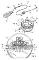
- FIG. 2 illustrates an enlarged perspective view of the flow regulator 22, provided in accordance with one aspect of the present invention.
- the flow regulator 22 has a generally circular profile when viewed from an angle normal to the control surface 23.
- Surface 23 is provided with a selector knob 108 which may be rotated through a series of positions which provide a graduated series of different flow rates.
- an "off" position may additionally be provided for completely interrupting the flow.
- Relative position of the knob 108 may be determined by reference marker 107 which may comprise a painted stripe or groove.
- annular flange 109 Extending radially outwardly from the knob 108 is an annular flange 109.
- the annular flange 109 is optimally provided with indicial markings 111 which correspond to the different flow rates of the regulator 22.
- the influent channel 36 and the effluent channel 38 are conveniently coaxially aligned so that they may function as pivots for transparent cover 39.
- a collar 41 is provided on each of channels 36 and 38, each collar 41 having an annular recess 43 for engaging an aperture 45 in cover 39.
- cover 39 may conveniently be pivoted to expose knob 108 for selection of a flow rate, as shown in Figure 2, and then pivoted back to cover knob 108 and protect against accidental readjustment.
- Cover 39 is thus optimally molded from any of a variety of rigid thermoplastic materials such as acrylic or styrene, which are substantially transparent to visible light to permit viewing of the selected flow rate.
- cover 39 may be provided with a locking means for preventing access to control knob 108 once cover 39 has been rotated into position.
- the present invention provides for the ready visual confirmation of the settings.
- the transparent housing may be permanently or temporarily locked in its protective position to prevent intentional or unintentional tampering with the setting.
- the cover 39 is shown in its protective configuration in phantom, and influent IV line 24 (shown in phantom) terminates in an influent channel 36 in the base 37 of flow regulator 22.
- IV line 24 may be secured in fluid communication with influent channel 36 by an adhesive, friction fit, or by mechanical locking structures such as a luer lock, as may be desired depending upon the intended use.
- the flow regulator will be provided with a short length of a connection line 24 which is secured to influent channel 36 by an adhesive material such as a quantity of a urethane-based UV cured epoxy or other material that will be substantially inert in the presence of a pharmaceutically active material to be dispensed through the flow regulator 22.
- the base 37 preferably comprises a radially symmetrical body such as a generally cylindrical body, best illustrated in Figure 4. All of the additional major components of the flow regulator 22, including the gasket 44, the valve guide 86, the hub 100, the knob 108, and flange 109 are also preferably substantially radially symmetrical about a common axis perpendicular to the axial end surface of the base 37. This configuration facilitates convenient operation of a rotational control, such as knob 108, as will be discussed.
- Base 37 may be formed in any of a variety of methods well known in the art, such as by injection molding of a thermoplastic resin. Selection of materials is not critical, as long as the components of the flow regulator are comprised of, or coated with, a material which is substantially inert in the presence of the medicinal fluid to be conducted therethrough. For example, acrylic or styrene are generally well suited for this purpose.
- fluid from the source 26 is driven through IV line 24 and into channel 36.
- Channel 36 communicates with an influent port 40, which, in the illustrated embodiment in Figure 3, is perpendicularly disposed to the longitudinal axis of channel 36.
- Port 40 terminates at an interface between the upper surface of base 37 and an adjacent gasket 44.
- Fluid exiting port 40 passes through a coaxially aligned aperture 42 in the gasket 44.
- the gasket 44 is preferably formed from an elastomeric material which exhibits good resilient sealing characteristics as will be described. Suitable materials for the gasket include known vulcanized synthetic polyisoprenes, as well as natural latex or silicone rubber, or blends of natural and synthetic rubber. Non-rubber gasket materials may also be used, either with a rubber coating or without, provided the gasket is capable of performing its function of sealing the variety of flow passages therethrough.
- the gasket 44 can be formed by punching from a stock sheet and boring or etching or drilling such as by mechanical drill or by laser to produce the apertures and depressions contained thereon; or by known molding processes as will be appreciated by one skilled in the art. Since portions of the gasket will be in contact with the medicinal fluid delivered through the flow regulator, at least those portions ( e.g. , the interior of aperture 42) should be composed of, or coated with, a material which will exhibit suitable stability for that purpose.
- the gasket is preferably radially symmetrical to accommodate the rotational operation of a cam 96 on the lower surface of knob 108, as will be discussed.
- the gasket 44 is substantially circular in shape so that it will fit within the circular depression 52, on the base 37, formed by an annular flange 54.
- the annular flange 54 is preferably provided with an interruption to form guide 56 for receiving a key 58 extending radially outwardly from the gasket 44 to facilitate manufacturing and to maintain the gasket 44 in proper rotational alignment with the base 37.
- alternative rotational alignment guides can be used such as one or more apertures on the gasket 44 for receiving corresponding pins extending from the upper surface of the base 37.
- the upper surface 60 of the gasket 44 is provided with a shallow depression 62, dimensioned to receive a flow control wafer 46.
- the influent aperture 42 traverses the gasket 44 in the area of the depression 62 for fluid communication with the control wafer 46.
- a plurality of effluent apertures 64 also pass through the gasket 44 in the region of the depression 62, also to provide fluid communication with the control wafer 46.
- the flow control wafer 46 comprises a first plate 112 having a fluid flow channel 114 formed thereon such as by chemical or laser etching techniques.
- the channel 114 is enclosed by a second plate 120 secured to the grooved surface of first plate 112 to form a wafer 46 having a flow restriction passageway therethrough.
- First plate 112 in accordance with the present invention preferably comprises silicon, for reasons which will become apparent, although other materials may be used which will accrue the advantages of the invention.
- the first plate 112 is preferably rectangular in shape to facilitate handling and manufacturing operations, although other shapes may be utilized if desired.
- Plate 112 has a thickness of from about 0.2 to about 3 or 4 mm, and preferably from about 0.2 to about 2 mm. The plate thickness should be at least sufficient to permit etching of a flow channel of the desired depth, while still maintaining the structural integrity of the plate for securing to the second plate 120 and mounting in the flow regulator 22.
- the fluid flow channel 114 may be formed in plate 112 in accordance with known techniques.
- plate 114 is a silicon wafer, and all fluid flow channels are preferably formed thereon by a single operation using semiconductor processing and micromachining techniques such as those described in U.S. Patent No. 4,626,244 to Reinicke.
- the first plate 112 is preferably a single silicon crystal in which the [100] plane is oriented parallel to the surface of the plate 112 in which the flow restriction grooves are to be formed. It has been determined that the use of an anisotropic etchant is advantageous, due to the ability of such etchants to etch at different rates in different directions along the crystal lattice. This characteristic permits formation of sharp edges and corners during the etching process.
- suitable anisotropic etchants are known, including hot alkaline solutions such as aqueous potassium hydroxide, aqueous sodium hydroxide, and a mixture of ethylene diamine, pyrocatchol and water, commonly known as EDP.
- each groove which is etched to completion is characterized by a sharp V configuration, with all of the wall portions of the grooves sloped inwardly and downwardly at an angle of 54.74° relative to the planar surface of the first plate 112.
- Preparation of low velocity flow regions such as the cavity 162 is accomplished by exposing a much wider surface area of the crystal to the etchant than that for the purpose of forming the fluid flow channel 114.
- the etchant for the purpose of forming the fluid flow channel 114.
- flat-bottomed grooves can be formed in a [100] crystal by stopping the etching operation prior to reaching the depth corresponding to the point of intersection of the converging [111] planes.
- narrow flow restriction passageways can be formed having precise triangular cross-sectional areas due to the convergence of the [111] planes, and larger, flat-bottomed areas can be formed by halting the etching process at a depth which is prior to convergence of the [111] planes which correspond to the initial width of the area exposed to the anisotropic etchant.
- a plurality of silicon first plates 112 are simultaneously formed from a single large silicon wafer.
- a second plate 120 is preferably secured to the entire wafer, as will be discussed, and the resultant sandwich cut into a plurality of control wafers 46.
- the wafer may be cut by utilizing a diamond saw, or by laser cutting.
- a tape is advantageously placed over either the first plate 112 or second plate 120 depending upon which has been provided with the influent port 118 and effluent apertures 122, 124, 126, etc. In this manner, dust produced during the sawing process will not enter the capillary groove network.
- the influent port 118 and apertures 122, 124 and 126 may either be mechanically drilled such as by an abrasive vapor blasting technique or they can be laser drilled.
- the plate 112 has a dimension in the x-axis direction of within the range of from about 1 to about 20 mm, and the y-axis dimension will typically fall within the same range.
- the plate 112 is approximately square, having an x-axis and y-axis dimension of the same length, from about 4 to 8 mm, although the size may be varied as a matter of design choice to accommodate the desired flow path dimensions.
- a second plate 120 is sealingly secured to the etched surface of the first plate 112, enclosing the flow channel 114 to form a control wafer 46 having a capillary tube therein. Sealing of the second plate 120 to the first plate 112 may be accomplished by electrobonding.
- a plurality of effluent apertures 122, 124, 126 are formed through the first plate 112, intersecting the capillary tube at various points intermediate the influent port 118 and the downstream end 119. Because the rate of flow of a fluid through a capillary tube is a function of the length of the flow path as will be described, each tap along the flow path will be associated with a different distance from influent port 118, and, hence, a different flow rate.
- the flow channel 114 has an upstream end 116, a downstream end 119 and an influent port 118 extending through the first plate 112, for providing fluid communication with aperture 42 in gasket 44.
- the length of flow channel 114, the overall dimension of the control wafer 46 and the slowest delivery rate of which the system is capable are all interrelated, due to the known relationship of the flow rate through a capillary tube to the capillary tube's cross-sectional area and length.
- the flow channel 114 may advantageously be formed into a spiral, doubled back on itself, or any other space conserving pattern.
- the pattern illustrated in Figure 5 is but a simplified representation of the preferred rectangular spiral design of Figure 8. By simplified, it is meant that while the illustrated channel 114 in Figure 5 goes through approximately two and one-half complete revolutions, the channel 114 in the preferred embodiment, as shown in Figure 8, is actually contemplated to have anywhere from about 1 to as many as about 30 revolutions or more, depending upon the cross-sectional area of the channel and desired rate parameters.
- the cross-sectional configuration of the flow channel 114 is essentially triangular as a result of the preferred manufacturing technique. However, other cross-sectional configurations may be utilized without departing from the present invention. In an approximately equilateral triangular configuration, the channel will optimally have side lengths within the range from .05 to about .2 mm, which equate to a cross-sectional area of within the range of from about .002 mm2 to about .04 mm2.
- a cross-sectional area for the flow channel may depend upon the desired range of flow rates for the flow regulator 22, the flow channel pattern, and machining or other processing tolerances among other factors. Although there is no theoretical lower limit to the cross-sectional area of the flow passageway, the smaller sizes are more susceptible to blockage and possibly viscosity of the fluid will have a more profound effect so that different medications would behave differently. Similarly, there is no theoretical limit to the maximum diameter or cross-sectional area of the flow channel, except that at a certain point the channel will no longer restrict the flow of fluid to a useful rate for the purpose of the present invention, as will be readily apparent to one of skill in the art.
- flow channel 140 in first plate 112 is in fluid communication with aperture 42 and influent port 40 of the base 37 ( Figure 3) by means of wafer influent port 118.
- the first plate 112 of the preferred embodiment of the control wafer 46 also contains a filter area 160, associated with the upstream end of flow channel 140, and also high flow rate channels 142 and 144, as will be discussed.
- the filter area 160 contains a low velocity cavity 162 and a plurality of influent filter channels 166 as shown enlarged in Figure 9. Fluid entering the control wafer 146, through the wafer influent port 118 is divided into the plurality of influent filter channels 166.
- the influent filter channels 166 serve to restrain any foreign matter of size sufficient to block the high flow rate channels 142, 144 or the low flow rate channel 140. It is therefore preferable that the influent filter channels 166 be of the same or, more preferably, of smaller cross-sectional area than the low flow rate channel 140.
- the number of filter channels 166 is a function of their cross-sectional areas.
- the sum of the areas of channels 166 will be significantly greater than that of flow channel 140, so that the filter does not become a rate limiting structure.
- the preferred embodiment is able to trap foreign particulate matter in a filter channel 166 without effecting the desired flow rate.
- Cavity 162 functions to manifold the effluent ends of all of the channels 166 for introduction into flow channel 140. In addition, cavity 162 may provide some further filtration due to the reduced velocity therein. Because of the large cross-sectional area of cavity 162 as compared to the cross-sectional area of the low flow rate channel 140 or either of the high flow rate channels 142, 144, the fluid velocity in cavity 162 is substantially less than in flow channels 140, 142, 144. Thus, the low fluid flow velocity in cavity 162 may permit the sedimentation of foreign particular matter which may have passed through the influent filter channels 166.
- Channel 140 is in fluid communication with the cavity 162 by means of a filter aperture 130.
- the distal end of channel 140 terminates at downstream end 150.
- a plurality of apertures 172, 174, 176, 178, 180, and 182. Any one of these apertures 172, 174, 176, 178, 180, and 182 may be selectively fluidly connected to the effluent port 50, as described infra .
- the apertures 172, 174, 176, 178, 180, and 182 are disposed along the length of the low flow rate channel 140 such that each aperture is disposed at a preselected distance along flow channel 140, and therefore corresponds to a unique, predetermined flow rate.
- aperture 172 in a specific embodiment of the present invention is positioned at a flow channel length of approximately 10.29 cm from the filter aperture 130, the flow channel 140 having a cross-sectional area of approximately .045 cm. Assuming all other apertures 174, 176, 178, 180 and 182 are closed, the position of the low flow rate aperture 172 provides a flow rate of approximately 1.65 milliliters per hour.
- Aperture 174 is positioned at a length of approximately 5.13 cm along channel 140 from filter aperture 130. If all other effluent apertures along flow channel 140 are closed, the position of the low flow rate aperture 174 provides a flow rate of approximately 3.03 milliliters per hour.
- Aperture 176 is positioned at a length of approximately 3.43 cm along channel 140 from filter aperture 130. Thereby, the position of the low flow rate aperture 176 provides a flow rate through the aperture 176 of approximately 4.95 milliliters per hour.
- aperture 178 is positioned at a length of approximately 1.60 cm along low flow rate channel 140 from the filter aperture 130. Thereby, the position of aperture 178 results in a flow rate through the aperture 178 of approximately 10.6 milliliters per hour.
- Aperture 180 is positioned at a length of approximately .724 cm along channel 140 from aperture 130. The position of aperture 180 provides a flow rate of approximately 23.41 milliliters per hour.
- aperture 182 is positioned at a length of approximately .176 cm along flow channel 140 from the low flow rate channel filter aperture 130. Thereby, the position of the aperture 182 provides a flow rate of approximately 50.0 milliliters per hour. As will be appreciated by one skilled in the art, more or fewer effluent apertures can be provided, at various desired flow rates.
- high flow rate channels 142 and 144 are provided in fluid communication with cavity 162 by means of apertures 132 and 134, respectively.
- the high flow rate channels 142 and 144 terminate at downstream ends 152 and 154 respectively.
- the high flow rate aperture 170 is in communication with both high flow rate channels 142 and 144.
- the high flow rate aperture 170 is positioned a length of .146 cm along the high flow rate channels 142, 144 from apertures 132, 134.
- the parallel flow arrangement effectively doubles the area of the single flow path to provide a flow rate of approximately 100 mm per hour.
- control wafer 46 can be constructed having a plurality of discrete flow channels, which may be arranged so that they are substantially parallel to each other, or radiate from a central location. Each discrete channel is provided with an upstream end which is in valved communication with the fluid source, and a downstream end, each of which is conveniently manifolded to a common effluent channel. In this embodiment, rotation of control knob 108 would successively increase or decrease the number of flow paths through which fluid would flow, in series or in parallel as desired, thereby affecting the overall flow rate. In a multiple channel embodiment, the channels could all have the same cross-sectional area, or differing cross-sectional areas can be provided.
- the valve guide 86, gasket 44 and other components of the flow regular 22 of the present invention can be readily adapted to all of the foregoing variations of control wafer 46.
- the flow channel 114 can extend along more than a single surface of plate 112, or along additional plates.
- flow channel 114 can pass through an aperture (not illustrated) in plate 112 to the backside thereof, which can be provided with a further length of a flow channel. That further channel would be enclosed to form a capillary tube by the addition of a third plate (not illustrated) secured to first plate 112 on the opposite side from plate 120.
- a third plate not illustrated
- each of the effluent apertures 172, 174, 176, 178, 180 and 182 along the length of the low flow rate channel 140 and tap 170 of the high flow rate channels 142, 144 is in communication with a corresponding effluent aperture 64 in the depression 62 of the gasket 44 (see Figure 4).
- each effluent aperture 64 in the gasket 44 communicates with a corresponding flow channel 80 on the surface of base 37. It is to be understood that each of the plurality of flow channels 80 in base 37 function in a similar manner, so that only one need be described in detail herein.
- Effluent aperture 64 in the gasket 44 is in valved communication by way of the flow channel 80 and the valve chamber 82 with common drain 84 to which each of the plurality of flow channels are manifolded.
- fluid exiting channel 140 by way of any of effluent apertures 172, 174, 176, 178, 180 or 182 will pass through a corresponding channel 80 and valve chamber 82 into drain 84. From drain 84, fluid is directed to effluent channel 38 by port 50.
- valve guide 86 is disposed on the upper side of the gasket 44.
- the valve guide 86 may be injection molded or die stamped and drilled as will be appreciated by one of skill in the art. Although it may be convenient to form the valve guide 86 from the same material as base 37, that is not necessary since the material of guide 86 will not contact the medicinal fluid and hence need not exhibit the same level of biocompatibility and chemical stability.
- the valve guide 86 is conveniently provided with a notch 87 which engages a pin 89 projecting axially upwardly from annular flange 54 on base 37.
- the valve guide 86 contains a plurality of perforations 88 therethrough, preferably radially symmetrically distributed about the periphery of the valve guide 86 as seen in Figure 4.
- Corresponding to each perforation 88 in the valve guide 86 is a depression 90 in the gasket 44.
- the depression 90 may comprise different depths or be eliminated entirely as will be appreciated by one of skill in the art.
- Piston 94 is capable of axial reciprocating movement between a first open position and a second closed position.
- fluid in the flow channel 80 formed between the base 37 and the gasket 44, flows freely across the valve chamber 82 and into the drain 84.
- the piston 94 is forced axially downwardly into the second position by lower cam surface 96 on knob 108, which will be discussed, the piston 94 extends through the perforation 88 and elastically deforms the diaphragm 92 in such a manner as to occlude the corresponding valve chamber 82, thereby preventing passage of fluid therethrough.
- the terminal end 98 of the piston 94 and the bottom of valve chamber 82 can be provided with complementary surface configurations.
- valve chambers 82 and fluid passageways 80 and 84 are formed into the bottom side of the gasket 44. This embodiment will operate in substantially the same way as the foregoing embodiment, as will be appreciated by one of skill in the art.
- each of the plurality of pistons 94 can be individually formed and mounted in the flow regulator 22, or take the form of spherical beads in a race, it is convenient to mold them into a unitary structure such as that illustrated in Figure 4.
- each of the plurality of pistons 94 is radially symmetrically spaced about a central hub 100 and secured thereto by means of a resilient arm 102.
- Each piston 94 comprises a substantially tubular body terminating at its terminal end 98 in a conical taper to enhance the seal formed between the diaphragm 92 and the valve chamber 82.
- each piston is provided with a radially outwardly extending annular collar 104.
- the collar 104 functions to provide an enlarged upper surface 106 for slidably engaging the lower surface of a rotatable annular cam 96 which may be rotationally positioned by a selector knob 108.
- the lower cam surface 96 of selector knob 108 contains a recess 110 for receiving any one of the plurality of the surfaces 106.
- Fluid which has traversed the control wafer 46 and an open valve chamber 82 is collected in the common drain line 84 and forced through the effluent port 50 (See Figure 3) into the effluent channel 38. From there, the fluid is conducted via IV line 25 to the patient.
- any one selected valve may be opened, while maintaining all of the remaining valves closed.
- any given one of the preselected lengths of the capillary tube in the control wafer can be selected. Since the effective length of the capillary tube is the rate regulating step, any of a plurality of predetermined flow rates may be selected, such as from within a range of from 1 milliliter or less per hour at the low rate end to 100 milliliters or more per hour at the high flow rate end of the range.
- one flow regulator in accordance with the present invention exhibited flow rates of approximately 2.08, 4.17, 6.25, 12.5, 25, 50 and 100 milliliters per hour.
- the selector knob 108 is provided with coil spring 101 which has a tangentially projecting arm 103.
- the spring 101 is rotationally secured to the interior of the selector knob 108 (See Figure 3) with the arm 103 extending radially outwardly into the annular recess 105 in the underside of annular flange 109.
- the recess 105 is provided with radially inwardly extending teeth (not illustrated) into which the arm 103 is biased, so that the knob 108, when rotated, will distinctly snap from one position to the next.
Landscapes
- Engineering & Computer Science (AREA)
- Health & Medical Sciences (AREA)
- General Engineering & Computer Science (AREA)
- Hematology (AREA)
- Animal Behavior & Ethology (AREA)
- Anesthesiology (AREA)
- Biomedical Technology (AREA)
- Heart & Thoracic Surgery (AREA)
- Physics & Mathematics (AREA)
- Life Sciences & Earth Sciences (AREA)
- Vascular Medicine (AREA)
- General Health & Medical Sciences (AREA)
- Public Health (AREA)
- Veterinary Medicine (AREA)
- Fluid Mechanics (AREA)
- Mechanical Engineering (AREA)
- Infusion, Injection, And Reservoir Apparatuses (AREA)
- Flow Control (AREA)
Abstract
Description
- The present invention relates to medical infusion devices, and, more particularly, to variable flow rate regulators for accurately regulating the effluent flow from a source of pressurized fluid.
- Intravenous or other parenteral administration of fluids is routinely performed in hospitals, other medical facilities, and emergency sites in the field. Depending upon the nature of the infusate, it is desirable for the clinician to be able to accurately and rapidly select an appropriate rate of delivery. For example, infusion of normal saline or lactated Ringer's solution to achieve normovolemia during surgery or following trauma is typically accomplished at a relatively high flow rate. On the other hand, administration of certain antiarrythmics such as Lidocaine or Procanamide following myocardial infarction may desirably be accomplished at any of a variety of relatively slow rates. In addition, administration of certain antineoplastic agents must be performed at a very slow and constant rate over a prolonged period to avoid localized necrosis at the infusion site. Even the IV administration of antibiotics is desirable in some circumstances, at relatively slow delivery rates such as 50 cc over 90 minutes or more. Not only do a large variety of situations exist which each require unique flow rates, but it may also be desirable in certain applications to be able to vary the flow rate once infusion has commenced.
- A number of flow regulators have been developed from the simple adjustable clamp and counting of drips per minute to elaborate peristolic pump devices. Nonetheless, there remains a need for a variable flow regulator which is accurate, capable of providing any of a number of convenient preselected flow rates, and yet which is inexpensive to produce. In addition, there exists a need for such a device which is compact and simple to use, thereby accommodating the needs in the operating room, in the field, and of the ambulatory patient, while at the same time providing for precise delivery rates with minimal operator error and offering tamper-proof setting of the flow rate. Moreover, there exists a need to be able to quickly and accurately confirm the flow rate setting of the variable flow controller.
- In accordance with one aspect of the present invention, there is provided a variable rate fluid flow controller for providing a predetermined delivery rate from a pressurized source of fluid, comprising a housing having an influent port, an effluent port and at least two flow restriction paths therebetween. At least two valves are provided in the housing, each valve associated with a unique flow path, and a movable cam is provided for selectively opening and closing the valves. The flow paths may be disposed in series or parallel relationship, or may comprise a single length of flow restriction passageway having an influent port and a plurality of effluent apertures disposed along its length.
- Each flow path is optimally provided with a pinch valve, which preferably comprises a moveable wall which may be compressed by the cam to prevent fluid flow through the associated flow path. In accordance with one preferred embodiment, a piston is associated with each pinch valve, the piston moveable from a first position in which fluid is permitted to flow through the valve and a second position in which a flexible diaphragm is compressed to prevent fluid flow through the valve, the piston being moveable between the first and second positions in response to the rotational position of the cam.
- In accordance with a further aspect of the present invention, there is provided a flow regulator for use with the foregoing variable rate fluid flow controller. The flow regulator comprises a first plate having a flow channel on the surface thereof, and a second plate secured to the surface of the first plate and enclosing the flow channel to form a chip having a capillary tube therethrough. An influent port is provided on the chip in fluid communication with the capillary tube, and a plurality of effluent apertures are provided on the chip, each in fluid communication with the capillary tube at a different distance along its length from the influent port.
- Further features and advantages of the present invention will become apparent from the detailed description of preferred embodiments which follow, when taken together with the appended figures and claims.
-
- Figure 1 is a schematic representation of an infusion system which incorporates a flow regulator according to the present invention.
- Figure 2 is an enlarged perspective view of a flow regulator according to one embodiment of the present invention.
- Figure 3 is an elevational cross-sectional view taken along the lines 3-3 of Figure 2, of a flow regulator according to the present invention.
- Figure 4 is an exploded perspective view of the flow regulator illustrated in Figure 3.
- Figure 5 is a partial cut-away plan view of a simplified flow regulating wafer according to the present invention.
- Figure 6 is an elevational sectional view along the lines 6-6 of the flow control wafer in Figure 5.
- Figure 7 is an elevational sectional view along the lines 7-7 of the flow control wafer in Figure 5.
- Figure 8 is an overhead view of the preferred embodiment of the control wafer.
- Figure 9 is an enlarged overhead view of the filter area of the preferred control wafer of the present invention.
- Referring to Figure 1, there is disclosed an
infusion system 20 adapted for delivering a medication or other fluid contained in asource 26 to a patient (not illustrated). Thesource 26 may be any of a variety of known medication dispensers, from gravity feed IV bags to mechanical pumps. Preferably, however, the fluid source will be a relatively constant pressure delivery system, such as the Intermate® elastomeric bladder infusion pump disclosed in U.S. Patent No. 4,769,008 and commercially available from Infusion Systems Corporation of Huntington Beach, California. - The
infusion system 20 further comprises aflow regulator 22 according to the present invention, in fluid communication with thesource 26 by way of standard IVline 24. Fluid is conducted from theflow regulator 22 to a patient by way of IVline 25. - The
downstream end 28 of IVline 25 is optimally provided with astandard luer connection 29 or other connector adapted for convenient attachment to an IV needle, piggyback connection, or the like. In addition, to facilitate connection of theflow regulator 22 to asource 26, theupstream end 31 of IVline 24 is provided with aconnector 30 which may comprise a luer, snap fit, or other convenient connector known in the art. - Figure 2 illustrates an enlarged perspective view of the
flow regulator 22, provided in accordance with one aspect of the present invention. Theflow regulator 22 has a generally circular profile when viewed from an angle normal to thecontrol surface 23.Surface 23 is provided with aselector knob 108 which may be rotated through a series of positions which provide a graduated series of different flow rates. Optionally, an "off" position may additionally be provided for completely interrupting the flow. Relative position of theknob 108 may be determined byreference marker 107 which may comprise a painted stripe or groove. - Extending radially outwardly from the
knob 108 is anannular flange 109. Theannular flange 109 is optimally provided with indicial markings 111 which correspond to the different flow rates of theregulator 22. - The
influent channel 36 and theeffluent channel 38 are conveniently coaxially aligned so that they may function as pivots fortransparent cover 39. For this purpose, acollar 41 is provided on each ofchannels collar 41 having an annular recess 43 for engaging anaperture 45 incover 39. In this manner,cover 39 may conveniently be pivoted to exposeknob 108 for selection of a flow rate, as shown in Figure 2, and then pivoted back to coverknob 108 and protect against accidental readjustment. -
Cover 39 is thus optimally molded from any of a variety of rigid thermoplastic materials such as acrylic or styrene, which are substantially transparent to visible light to permit viewing of the selected flow rate. Optionally,cover 39 may be provided with a locking means for preventing access tocontrol knob 108 oncecover 39 has been rotated into position. - By incorporating a transparent housing that rotates to cover the settings, the present invention provides for the ready visual confirmation of the settings. In addition, the transparent housing may be permanently or temporarily locked in its protective position to prevent intentional or unintentional tampering with the setting.
- Referring to Figure 3, the
cover 39 is shown in its protective configuration in phantom, and influent IV line 24 (shown in phantom) terminates in aninfluent channel 36 in thebase 37 offlow regulator 22. - IV
line 24 may be secured in fluid communication withinfluent channel 36 by an adhesive, friction fit, or by mechanical locking structures such as a luer lock, as may be desired depending upon the intended use. Preferably, the flow regulator will be provided with a short length of aconnection line 24 which is secured toinfluent channel 36 by an adhesive material such as a quantity of a urethane-based UV cured epoxy or other material that will be substantially inert in the presence of a pharmaceutically active material to be dispensed through theflow regulator 22. - Although many physical configurations would be adaptable for use with the present invention, the
base 37 preferably comprises a radially symmetrical body such as a generally cylindrical body, best illustrated in Figure 4. All of the additional major components of theflow regulator 22, including thegasket 44, thevalve guide 86, the hub 100, theknob 108, andflange 109 are also preferably substantially radially symmetrical about a common axis perpendicular to the axial end surface of thebase 37. This configuration facilitates convenient operation of a rotational control, such asknob 108, as will be discussed. -
Base 37 may be formed in any of a variety of methods well known in the art, such as by injection molding of a thermoplastic resin. Selection of materials is not critical, as long as the components of the flow regulator are comprised of, or coated with, a material which is substantially inert in the presence of the medicinal fluid to be conducted therethrough. For example, acrylic or styrene are generally well suited for this purpose. - Referring to Figures 3 and 4, fluid from the
source 26 is driven through IVline 24 and intochannel 36.Channel 36 communicates with aninfluent port 40, which, in the illustrated embodiment in Figure 3, is perpendicularly disposed to the longitudinal axis ofchannel 36.Port 40 terminates at an interface between the upper surface ofbase 37 and anadjacent gasket 44. -
Fluid exiting port 40 passes through a coaxially alignedaperture 42 in thegasket 44. Thegasket 44 is preferably formed from an elastomeric material which exhibits good resilient sealing characteristics as will be described. Suitable materials for the gasket include known vulcanized synthetic polyisoprenes, as well as natural latex or silicone rubber, or blends of natural and synthetic rubber. Non-rubber gasket materials may also be used, either with a rubber coating or without, provided the gasket is capable of performing its function of sealing the variety of flow passages therethrough. - The
gasket 44 can be formed by punching from a stock sheet and boring or etching or drilling such as by mechanical drill or by laser to produce the apertures and depressions contained thereon; or by known molding processes as will be appreciated by one skilled in the art. Since portions of the gasket will be in contact with the medicinal fluid delivered through the flow regulator, at least those portions (e.g., the interior of aperture 42) should be composed of, or coated with, a material which will exhibit suitable stability for that purpose. - Although any of a variety of configurations may be selected, the gasket is preferably radially symmetrical to accommodate the rotational operation of a
cam 96 on the lower surface ofknob 108, as will be discussed. In the illustrated embodiment as shown in Figure 4, thegasket 44 is substantially circular in shape so that it will fit within the circular depression 52, on thebase 37, formed by anannular flange 54. As shown in Figure 4, theannular flange 54 is preferably provided with an interruption to formguide 56 for receiving a key 58 extending radially outwardly from thegasket 44 to facilitate manufacturing and to maintain thegasket 44 in proper rotational alignment with thebase 37. Although not shown, alternative rotational alignment guides can be used such as one or more apertures on thegasket 44 for receiving corresponding pins extending from the upper surface of thebase 37. - The
upper surface 60 of thegasket 44 is provided with ashallow depression 62, dimensioned to receive aflow control wafer 46. Theinfluent aperture 42 traverses thegasket 44 in the area of thedepression 62 for fluid communication with thecontrol wafer 46. In addition, a plurality ofeffluent apertures 64 also pass through thegasket 44 in the region of thedepression 62, also to provide fluid communication with thecontrol wafer 46. - Referring to Figures 5-7, there is disclosed a simplified
flow control wafer 46 according to the present invention. Theflow control wafer 46 comprises afirst plate 112 having afluid flow channel 114 formed thereon such as by chemical or laser etching techniques. Thechannel 114 is enclosed by asecond plate 120 secured to the grooved surface offirst plate 112 to form awafer 46 having a flow restriction passageway therethrough.First plate 112 in accordance with the present invention preferably comprises silicon, for reasons which will become apparent, although other materials may be used which will accrue the advantages of the invention. - The
first plate 112 is preferably rectangular in shape to facilitate handling and manufacturing operations, although other shapes may be utilized if desired.Plate 112 has a thickness of from about 0.2 to about 3 or 4 mm, and preferably from about 0.2 to about 2 mm. The plate thickness should be at least sufficient to permit etching of a flow channel of the desired depth, while still maintaining the structural integrity of the plate for securing to thesecond plate 120 and mounting in theflow regulator 22. - The
fluid flow channel 114, and other flow channels to be described, may be formed inplate 112 in accordance with known techniques. In the preferred embodiment of the present invention,plate 114 is a silicon wafer, and all fluid flow channels are preferably formed thereon by a single operation using semiconductor processing and micromachining techniques such as those described in U.S. Patent No. 4,626,244 to Reinicke. - The
first plate 112 is preferably a single silicon crystal in which the [100] plane is oriented parallel to the surface of theplate 112 in which the flow restriction grooves are to be formed. It has been determined that the use of an anisotropic etchant is advantageous, due to the ability of such etchants to etch at different rates in different directions along the crystal lattice. This characteristic permits formation of sharp edges and corners during the etching process. A variety of suitable anisotropic etchants are known, including hot alkaline solutions such as aqueous potassium hydroxide, aqueous sodium hydroxide, and a mixture of ethylene diamine, pyrocatchol and water, commonly known as EDP. - The inherent etching characteristics of the above etchants in the silicon crystal permit the etching of passageways having different cross-sectional areas by utilizing a mask which leaves exposed areas on the silicon wafer of different widths. Regardless of the starting width, as the etching operation proceeds the sidewalls of the grooves slope inwardly along the converging [111] planes of the silicon wafer, to the point of intersection of the [111] planes, as will be understood by one of skill in the art. Thus, each groove which is etched to completion is characterized by a sharp V configuration, with all of the wall portions of the grooves sloped inwardly and downwardly at an angle of 54.74° relative to the planar surface of the
first plate 112. - Preparation of low velocity flow regions such as the
cavity 162, is accomplished by exposing a much wider surface area of the crystal to the etchant than that for the purpose of forming thefluid flow channel 114. Utilizing the above-mentioned anisotropic etchants, flat-bottomed grooves can be formed in a [100] crystal by stopping the etching operation prior to reaching the depth corresponding to the point of intersection of the converging [111] planes. Thus, under the same etching conditions, narrow flow restriction passageways can be formed having precise triangular cross-sectional areas due to the convergence of the [111] planes, and larger, flat-bottomed areas can be formed by halting the etching process at a depth which is prior to convergence of the [111] planes which correspond to the initial width of the area exposed to the anisotropic etchant. - Optimally, a plurality of silicon
first plates 112 are simultaneously formed from a single large silicon wafer. After the etching process, asecond plate 120 is preferably secured to the entire wafer, as will be discussed, and the resultant sandwich cut into a plurality ofcontrol wafers 46. The wafer may be cut by utilizing a diamond saw, or by laser cutting. In a diamond saw process, a tape is advantageously placed over either thefirst plate 112 orsecond plate 120 depending upon which has been provided with theinfluent port 118 andeffluent apertures - The
influent port 118 andapertures - Referring to the representational plan view of Figure 5, the
plate 112 has a dimension in the x-axis direction of within the range of from about 1 to about 20 mm, and the y-axis dimension will typically fall within the same range. Preferably, theplate 112 is approximately square, having an x-axis and y-axis dimension of the same length, from about 4 to 8 mm, although the size may be varied as a matter of design choice to accommodate the desired flow path dimensions. - As shown in Figures 6 and 7, a
second plate 120 is sealingly secured to the etched surface of thefirst plate 112, enclosing theflow channel 114 to form acontrol wafer 46 having a capillary tube therein. Sealing of thesecond plate 120 to thefirst plate 112 may be accomplished by electrobonding. - Referring to Figure 5, a plurality of
effluent apertures first plate 112, intersecting the capillary tube at various points intermediate theinfluent port 118 and the downstream end 119. Because the rate of flow of a fluid through a capillary tube is a function of the length of the flow path as will be described, each tap along the flow path will be associated with a different distance frominfluent port 118, and, hence, a different flow rate. - Thus, as shown in Figure 5, the
flow channel 114 has anupstream end 116, a downstream end 119 and aninfluent port 118 extending through thefirst plate 112, for providing fluid communication withaperture 42 ingasket 44. The length offlow channel 114, the overall dimension of thecontrol wafer 46 and the slowest delivery rate of which the system is capable are all interrelated, due to the known relationship of the flow rate through a capillary tube to the capillary tube's cross-sectional area and length. This relationship is mathematically described by Poiseuille's Law, as expressed in the equation:
Q = (Pr⁴)/8Ln
for a capillary having a circular cross-sectional internal area, where Q is the flow rate in cc/sec through the capillary tube, P is the pressure drop through the tube in dynes/cm², r is the internal radius of the tube in cm, L is the length of the tube in cm, and n is the viscosity in poise. The flow rate through theflow channel 114 is thus a function of the channel's cross-sectional area and the channel's length, each of which can be varied as desired to accommodate manufacturing tolerances or other considerations. Although it is possible to perform a series of calculations to determine precise flow rates based upon flow channel dimensions, it may alternatively be desirable to empirically measure flow rates and optimize dimensions by trial and error. - In order to permit a length of capillary tube which may be greatly in excess of the dimensions of the
flow control wafer 46, theflow channel 114 may advantageously be formed into a spiral, doubled back on itself, or any other space conserving pattern. Thus, the pattern illustrated in Figure 5 is but a simplified representation of the preferred rectangular spiral design of Figure 8. By simplified, it is meant that while the illustratedchannel 114 in Figure 5 goes through approximately two and one-half complete revolutions, thechannel 114 in the preferred embodiment, as shown in Figure 8, is actually contemplated to have anywhere from about 1 to as many as about 30 revolutions or more, depending upon the cross-sectional area of the channel and desired rate parameters. - The cross-sectional configuration of the
flow channel 114, illustrated in Figure 6, is essentially triangular as a result of the preferred manufacturing technique. However, other cross-sectional configurations may be utilized without departing from the present invention. In an approximately equilateral triangular configuration, the channel will optimally have side lengths within the range from .05 to about .2 mm, which equate to a cross-sectional area of within the range of from about .002 mm² to about .04 mm². - Selection of a cross-sectional area for the flow channel may depend upon the desired range of flow rates for the
flow regulator 22, the flow channel pattern, and machining or other processing tolerances among other factors. Although there is no theoretical lower limit to the cross-sectional area of the flow passageway, the smaller sizes are more susceptible to blockage and possibly viscosity of the fluid will have a more profound effect so that different medications would behave differently. Similarly, there is no theoretical limit to the maximum diameter or cross-sectional area of the flow channel, except that at a certain point the channel will no longer restrict the flow of fluid to a useful rate for the purpose of the present invention, as will be readily apparent to one of skill in the art. - In the preferred embodiment of the
control wafer 46, as shown in Figure 8,flow channel 140 infirst plate 112 is in fluid communication withaperture 42 andinfluent port 40 of the base 37 (Figure 3) by means of waferinfluent port 118. Thefirst plate 112 of the preferred embodiment of thecontrol wafer 46 also contains a filter area 160, associated with the upstream end offlow channel 140, and also highflow rate channels - Referring to Figure 8, the filter area 160 contains a
low velocity cavity 162 and a plurality ofinfluent filter channels 166 as shown enlarged in Figure 9. Fluid entering the control wafer 146, through thewafer influent port 118 is divided into the plurality ofinfluent filter channels 166. Theinfluent filter channels 166 serve to restrain any foreign matter of size sufficient to block the highflow rate channels flow rate channel 140. It is therefore preferable that theinfluent filter channels 166 be of the same or, more preferably, of smaller cross-sectional area than the lowflow rate channel 140. The number offilter channels 166 is a function of their cross-sectional areas. Optimally, the sum of the areas ofchannels 166 will be significantly greater than that offlow channel 140, so that the filter does not become a rate limiting structure. Thus, the preferred embodiment is able to trap foreign particulate matter in afilter channel 166 without effecting the desired flow rate. - After passing through the
influent filter channels 166, the fluid enterslow velocity cavity 162.Cavity 162 functions to manifold the effluent ends of all of thechannels 166 for introduction intoflow channel 140. In addition,cavity 162 may provide some further filtration due to the reduced velocity therein. Because of the large cross-sectional area ofcavity 162 as compared to the cross-sectional area of the lowflow rate channel 140 or either of the highflow rate channels cavity 162 is substantially less than inflow channels cavity 162 may permit the sedimentation of foreign particular matter which may have passed through theinfluent filter channels 166. - Referring to Figure 8, the preferred embodiment is provided with a
flow restriction channel 140.Channel 140 is in fluid communication with thecavity 162 by means of afilter aperture 130. The distal end ofchannel 140 terminates atdownstream end 150. Positioned betweenfilter aperture 130 anddownstream end 150 are a plurality ofapertures apertures effluent port 50, as described infra. Theapertures flow rate channel 140 such that each aperture is disposed at a preselected distance alongflow channel 140, and therefore corresponds to a unique, predetermined flow rate. - For example,
aperture 172 in a specific embodiment of the present invention is positioned at a flow channel length of approximately 10.29 cm from thefilter aperture 130, theflow channel 140 having a cross-sectional area of approximately .045 cm. Assuming allother apertures flow rate aperture 172 provides a flow rate of approximately 1.65 milliliters per hour. -
Aperture 174 is positioned at a length of approximately 5.13 cm alongchannel 140 fromfilter aperture 130. If all other effluent apertures alongflow channel 140 are closed, the position of the lowflow rate aperture 174 provides a flow rate of approximately 3.03 milliliters per hour. -
Aperture 176 is positioned at a length of approximately 3.43 cm alongchannel 140 fromfilter aperture 130. Thereby, the position of the lowflow rate aperture 176 provides a flow rate through theaperture 176 of approximately 4.95 milliliters per hour. - Similarly,
aperture 178 is positioned at a length of approximately 1.60 cm along lowflow rate channel 140 from thefilter aperture 130. Thereby, the position ofaperture 178 results in a flow rate through theaperture 178 of approximately 10.6 milliliters per hour. -
Aperture 180 is positioned at a length of approximately .724 cm alongchannel 140 fromaperture 130. The position ofaperture 180 provides a flow rate of approximately 23.41 milliliters per hour. - Finally,
aperture 182 is positioned at a length of approximately .176 cm alongflow channel 140 from the low flow ratechannel filter aperture 130. Thereby, the position of theaperture 182 provides a flow rate of approximately 50.0 milliliters per hour. As will be appreciated by one skilled in the art, more or fewer effluent apertures can be provided, at various desired flow rates. - For providing higher flow rates, two or more flow restriction passageways can be coupled in parallel. Thus, in accordance with a further aspect of the present invention, high
flow rate channels cavity 162 by means ofapertures flow rate channels filter apertures flow rate aperture 170 is in communication with both highflow rate channels - The high
flow rate aperture 170 is positioned a length of .146 cm along the highflow rate channels apertures - An alternative design (not illustrated) of the
control wafer 46 can be constructed having a plurality of discrete flow channels, which may be arranged so that they are substantially parallel to each other, or radiate from a central location. Each discrete channel is provided with an upstream end which is in valved communication with the fluid source, and a downstream end, each of which is conveniently manifolded to a common effluent channel. In this embodiment, rotation ofcontrol knob 108 would successively increase or decrease the number of flow paths through which fluid would flow, in series or in parallel as desired, thereby affecting the overall flow rate. In a multiple channel embodiment, the channels could all have the same cross-sectional area, or differing cross-sectional areas can be provided. Thevalve guide 86,gasket 44 and other components of the flow regular 22 of the present invention can be readily adapted to all of the foregoing variations ofcontrol wafer 46. - Moreover, in accordance with a preferred embodiment of the present invention, the
flow channel 114 can extend along more than a single surface ofplate 112, or along additional plates. For example,flow channel 114 can pass through an aperture (not illustrated) inplate 112 to the backside thereof, which can be provided with a further length of a flow channel. That further channel would be enclosed to form a capillary tube by the addition of a third plate (not illustrated) secured tofirst plate 112 on the opposite side fromplate 120. In this manner, significant design flexibility is permitted by the present invention to accommodate a wide variety of flow restriction channel lengths and designs. - Referring to Figure 3, when the
control wafer 46 is positioned within thedepression 62 of thegasket 44, theaperture 42 aligns with theinfluent port 118 on thecontrol wafer 46. Fluid passing from theinfluent channel 36 through theport 40 and theaperture 42 will thus proceed to enter theflow channel 140 by way of theinfluent port 118. - Each of the
effluent apertures flow rate channel 140 and tap 170 of the highflow rate channels effluent aperture 64 in thedepression 62 of the gasket 44 (see Figure 4). Similarly, eacheffluent aperture 64 in thegasket 44 communicates with acorresponding flow channel 80 on the surface ofbase 37. It is to be understood that each of the plurality offlow channels 80 inbase 37 function in a similar manner, so that only one need be described in detail herein.Effluent aperture 64 in thegasket 44 is in valved communication by way of theflow channel 80 and thevalve chamber 82 withcommon drain 84 to which each of the plurality of flow channels are manifolded. Thus,fluid exiting channel 140 by way of any ofeffluent apertures channel 80 andvalve chamber 82 intodrain 84. Fromdrain 84, fluid is directed toeffluent channel 38 byport 50. - As shown in Figure 4, in order to form a valve in each of
valve chambers 82, avalve guide 86 is disposed on the upper side of thegasket 44. Thevalve guide 86 may be injection molded or die stamped and drilled as will be appreciated by one of skill in the art. Although it may be convenient to form thevalve guide 86 from the same material asbase 37, that is not necessary since the material ofguide 86 will not contact the medicinal fluid and hence need not exhibit the same level of biocompatibility and chemical stability. In order to maintain the correct rotational alignment, thevalve guide 86 is conveniently provided with anotch 87 which engages apin 89 projecting axially upwardly fromannular flange 54 onbase 37. - The
valve guide 86 contains a plurality ofperforations 88 therethrough, preferably radially symmetrically distributed about the periphery of thevalve guide 86 as seen in Figure 4. Corresponding to eachperforation 88 in thevalve guide 86 is adepression 90 in thegasket 44. At the bottom ofdepression 90, there remains a thin,resilient diaphragm 92. Depending upon the thickness and elasticity of thegasket 44, and the dimensions of thevalve chamber 82, thedepression 90 may comprise different depths or be eliminated entirely as will be appreciated by one of skill in the art. - Disposed within or coaxially above each
perforation 88 is apiston 94.Piston 94 is capable of axial reciprocating movement between a first open position and a second closed position. When in the open position, in which thediaphragm 92 is relatively planar, fluid in theflow channel 80, formed between the base 37 and thegasket 44, flows freely across thevalve chamber 82 and into thedrain 84. When thepiston 94 is forced axially downwardly into the second position bylower cam surface 96 onknob 108, which will be discussed, thepiston 94 extends through theperforation 88 and elastically deforms thediaphragm 92 in such a manner as to occlude the correspondingvalve chamber 82, thereby preventing passage of fluid therethrough. To facilitate the sealing function, theterminal end 98 of thepiston 94 and the bottom ofvalve chamber 82 can be provided with complementary surface configurations. - In an alternate embodiment (not illustrated), the
valve chambers 82 andfluid passageways gasket 44. This embodiment will operate in substantially the same way as the foregoing embodiment, as will be appreciated by one of skill in the art. - Although each of the plurality of
pistons 94 can be individually formed and mounted in theflow regulator 22, or take the form of spherical beads in a race, it is convenient to mold them into a unitary structure such as that illustrated in Figure 4. In this embodiment, each of the plurality ofpistons 94 is radially symmetrically spaced about a central hub 100 and secured thereto by means of aresilient arm 102. Eachpiston 94 comprises a substantially tubular body terminating at itsterminal end 98 in a conical taper to enhance the seal formed between thediaphragm 92 and thevalve chamber 82. - At its upper end, each piston is provided with a radially outwardly extending
annular collar 104. Thecollar 104 functions to provide an enlargedupper surface 106 for slidably engaging the lower surface of a rotatableannular cam 96 which may be rotationally positioned by aselector knob 108. Thelower cam surface 96 ofselector knob 108 contains arecess 110 for receiving any one of the plurality of thesurfaces 106. - When assembled, the lower surface of the
cam 96 bears down upon each of thepistons 94, thereby closing the corresponding valves, except for apiston 94 which is radially aligned withrecess 110. The resilient property of thediaphragm 92 together with that contributed by theresilient arm 102, if used, operate to provide an upward bias of eachpiston 94 againstlower cam surface 96. With regard to anypiston 94 which is rotationally aligned withrecess 110, the upward bias is sufficient to move that piston into the "open" position with thecollar 104 disposed withinrecess 110. In this manner, the correspondingdiaphragm 92 will resume its unstressed state and the correspondingvalve chamber 82 will freely permit the passage of fluid fromflow channel 80 intodrain 84. All other pistons will be in the "closed" position due to thecam 96. - Fluid which has traversed the
control wafer 46 and anopen valve chamber 82 is collected in thecommon drain line 84 and forced through the effluent port 50 (See Figure 3) into theeffluent channel 38. From there, the fluid is conducted viaIV line 25 to the patient. - By rotating
knob 108, any one selected valve may be opened, while maintaining all of the remaining valves closed. In this manner, any given one of the preselected lengths of the capillary tube in the control wafer can be selected. Since the effective length of the capillary tube is the rate regulating step, any of a plurality of predetermined flow rates may be selected, such as from within a range of from 1 milliliter or less per hour at the low rate end to 100 milliliters or more per hour at the high flow rate end of the range. For example, one flow regulator in accordance with the present invention exhibited flow rates of approximately 2.08, 4.17, 6.25, 12.5, 25, 50 and 100 milliliters per hour. - The
selector knob 108 is provided withcoil spring 101 which has a tangentially projectingarm 103. Thespring 101 is rotationally secured to the interior of the selector knob 108 (See Figure 3) with thearm 103 extending radially outwardly into theannular recess 105 in the underside ofannular flange 109. Therecess 105 is provided with radially inwardly extending teeth (not illustrated) into which thearm 103 is biased, so that theknob 108, when rotated, will distinctly snap from one position to the next. - Although this invention has been described in terms of certain preferred embodiments, other embodiments that are apparent to those of skill in the art are also within the scope of this invention. Accordingly, the scope of the invention is intended to be defined only by reference to the appended claims.
Claims (16)
(a) a housing [37] having an influent port [36], an effluent port [38], and a fluid flow path therebetween;
(b) a flow restriction channel [114] in the flow path, for regulating the rate of flow, said restriction channel having an influent end [118] and at least two effluent apertures [170, 172, 174, 176, 178, 180, 182] along its length;
(c) a valve in the housing associated with each of the apertures along the flow path; and
(d) a control for selectively opening any one of the valves and maintaining each additional valve closed;
wherein the opening of any one of the valves places the influent port [36] in fluid communication with the effluent port [38] by way of a unique length of flow restriction channel [114] associated with the open valve.
a) a housing [37] having an influent port [36], an effluent port [38], and a fluid flow path therebetween;
b) a plurality of flow restriction channels in the flow path, for regulating the rate of flow;
c) a plurality of normally closed valves in the housing, each valve associated with a different flow restriction channel; and
d) a control, for selectively opening any one of the valves;
wherein opening any one of the valves places the influent port in fluid-communication with the effluent port by way of a unique flow restriction channel associated with the open valve.
a housing [37] having an influent port [36], an effluent port [38] and at least two flow paths therebetween;
at least two pinch valves in the housing, each pinch valve associated with a unique flow path; and
a movable cam [96] for selectively opening and closing the pinch valves.
Applications Claiming Priority (2)
| Application Number | Priority Date | Filing Date | Title |
|---|---|---|---|
| US271730 | 1981-06-08 | ||
| US07/271,730 US5009251A (en) | 1988-11-15 | 1988-11-15 | Fluid flow control |
Publications (3)
| Publication Number | Publication Date |
|---|---|
| EP0369712A2 true EP0369712A2 (en) | 1990-05-23 |
| EP0369712A3 EP0369712A3 (en) | 1991-01-16 |
| EP0369712B1 EP0369712B1 (en) | 1994-04-06 |
Family
ID=23036828
Family Applications (1)
| Application Number | Title | Priority Date | Filing Date |
|---|---|---|---|
| EP89311727A Expired - Lifetime EP0369712B1 (en) | 1988-11-15 | 1989-11-13 | Fluid flow control |
Country Status (5)
| Country | Link |
|---|---|
| US (1) | US5009251A (en) |
| EP (1) | EP0369712B1 (en) |
| JP (1) | JPH02180274A (en) |
| CA (1) | CA1311396C (en) |
| DE (2) | DE68914405D1 (en) |
Cited By (22)
| Publication number | Priority date | Publication date | Assignee | Title |
|---|---|---|---|---|
| WO1996034639A1 (en) * | 1995-05-03 | 1996-11-07 | Tricumed Gmbh | Implantable diffusion pump |
| EP0836859A2 (en) * | 1996-10-15 | 1998-04-22 | Nissho Corporation | Multi stage type flow rate switching device |
| US5908414A (en) * | 1995-05-03 | 1999-06-01 | Tricumed Gmbh | Implantable infusion pump |
| US6165778A (en) * | 1993-11-02 | 2000-12-26 | Affymax Technologies N.V. | Reaction vessel agitation apparatus |
| EP0968732A3 (en) * | 1998-07-03 | 2001-01-31 | Daiken Iki Kabushiki Kaisha | Liquid discharge regulator and liquid feeder equipped with the same |
| EP1117459A1 (en) * | 1998-10-02 | 2001-07-25 | Science Incorporated | Fluid delivery apparatus with flow indicator and vial fill control |
| ES2167281A1 (en) * | 2000-11-21 | 2002-05-01 | Leventon S A | Pressure reducer and corresponding manufacturing process and application |
| EP1129739A3 (en) * | 1993-10-04 | 2003-05-02 | Research International, Inc. | Micromachined filters |
| EP1985321A1 (en) | 2007-04-26 | 2008-10-29 | Tricumed Medizintechnik GmbH | Pump, method for manufacturing pump and method for operating pump |
| WO2008142371A1 (en) * | 2007-05-17 | 2008-11-27 | Centrax Limited | Device for controlling the rate of flow of a fluid |
| EP2359886A1 (en) * | 2010-02-12 | 2011-08-24 | Debiotech S.A. | Micromechanic passive flow regulator |
| ES2385079A1 (en) * | 2012-05-08 | 2012-07-18 | Leventon S.A.U. | Pressure reducer for supplying drugs to a patient and corresponding production method |
| EP2626103A1 (en) * | 2012-02-08 | 2013-08-14 | Centrax Limited | Flow control device |
| WO2013191365A1 (en) * | 2012-06-19 | 2013-12-27 | 한국기계연구원 | Ringer's solution flow rate adjusting device |
| KR101440065B1 (en) * | 2012-11-20 | 2014-09-17 | 김춘규 | Flow rate regulator for intravenous fluid |
| WO2014177963A1 (en) * | 2013-04-30 | 2014-11-06 | Kimberly-Clark Worldwide, Inc. | Flow selector device alignment system |
| EP2083800A4 (en) * | 2006-10-19 | 2016-10-12 | Ambu As | Device and method for patient activated bolus administration |
| US9971358B2 (en) | 2013-01-10 | 2018-05-15 | Debiotech S.A. | Adjustable passive flow regulator |
| WO2019158997A1 (en) * | 2018-02-16 | 2019-08-22 | Cequr Sa | Devices and methods for flow restriction in a microfluidic circuit for drug delivery |
| WO2022129289A1 (en) * | 2020-12-18 | 2022-06-23 | Christoph Miethke Gmbh & Co. Kg | Adjustable implantable throttle |
| EP4052740A4 (en) * | 2019-11-01 | 2022-11-30 | Yong Hyun Kim | Liquid medicine flow rate regulating device |
| WO2023278274A1 (en) * | 2021-06-29 | 2023-01-05 | Carefusion 303, Inc. | Pressure-regulating connector for infusion |
Families Citing this family (84)
| Publication number | Priority date | Publication date | Assignee | Title |
|---|---|---|---|---|
| US5957890A (en) * | 1997-06-09 | 1999-09-28 | Minimed Inc. | Constant flow medication infusion pump |
| US6273133B1 (en) * | 1999-10-15 | 2001-08-14 | Baxter International Inc. | Fluid flow rate switching device |
| US6589205B1 (en) | 1999-12-17 | 2003-07-08 | Advanced Bionica Corporation | Externally-controllable constant-flow medication delivery system |
| US6227133B1 (en) | 1999-12-30 | 2001-05-08 | Donald Gross | Marine raw water manifold |
| AU2001283419A1 (en) * | 2000-08-18 | 2002-03-04 | Becton, Dickinson And Company | Constant rate fluid delivery device with selectable flow rate and titratable bolus button |
| KR100472044B1 (en) * | 2001-11-29 | 2005-03-08 | 메인텍 주식회사 | Device for regulating a volume of liquid medicine |
| US20040073175A1 (en) * | 2002-01-07 | 2004-04-15 | Jacobson James D. | Infusion system |
| DE60320639T2 (en) | 2002-01-16 | 2009-05-28 | Michael G. Carlsbad Simon | PRESSURE COMPENSATING IV RIVER REGULATOR |
| US8364229B2 (en) | 2003-07-25 | 2013-01-29 | Dexcom, Inc. | Analyte sensors having a signal-to-noise ratio substantially unaffected by non-constant noise |
| US7613491B2 (en) | 2002-05-22 | 2009-11-03 | Dexcom, Inc. | Silicone based membranes for use in implantable glucose sensors |
| US20030236489A1 (en) * | 2002-06-21 | 2003-12-25 | Baxter International, Inc. | Method and apparatus for closed-loop flow control system |
| BRPI0314599B1 (en) * | 2002-09-19 | 2015-03-17 | Kimberly Clark Co | A device for selectively regulating fluid flow, an infusion system for distributing selectable flow rates of a therapeutic liquid to a patient, and a device for regulating fluid flow from a pressurized source. |
| US9763609B2 (en) | 2003-07-25 | 2017-09-19 | Dexcom, Inc. | Analyte sensors having a signal-to-noise ratio substantially unaffected by non-constant noise |
| US9135402B2 (en) | 2007-12-17 | 2015-09-15 | Dexcom, Inc. | Systems and methods for processing sensor data |
| US20190357827A1 (en) | 2003-08-01 | 2019-11-28 | Dexcom, Inc. | Analyte sensor |
| US8626257B2 (en) | 2003-08-01 | 2014-01-07 | Dexcom, Inc. | Analyte sensor |
| US7591801B2 (en) | 2004-02-26 | 2009-09-22 | Dexcom, Inc. | Integrated delivery device for continuous glucose sensor |
| US8886273B2 (en) | 2003-08-01 | 2014-11-11 | Dexcom, Inc. | Analyte sensor |
| US20080119703A1 (en) | 2006-10-04 | 2008-05-22 | Mark Brister | Analyte sensor |
| US7920906B2 (en) | 2005-03-10 | 2011-04-05 | Dexcom, Inc. | System and methods for processing analyte sensor data for sensor calibration |
| US9247900B2 (en) | 2004-07-13 | 2016-02-02 | Dexcom, Inc. | Analyte sensor |
| US8364230B2 (en) | 2006-10-04 | 2013-01-29 | Dexcom, Inc. | Analyte sensor |
| US8364231B2 (en) | 2006-10-04 | 2013-01-29 | Dexcom, Inc. | Analyte sensor |
| US8425417B2 (en) | 2003-12-05 | 2013-04-23 | Dexcom, Inc. | Integrated device for continuous in vivo analyte detection and simultaneous control of an infusion device |
| US8287453B2 (en) | 2003-12-05 | 2012-10-16 | Dexcom, Inc. | Analyte sensor |
| US8423114B2 (en) | 2006-10-04 | 2013-04-16 | Dexcom, Inc. | Dual electrode system for a continuous analyte sensor |
| US11633133B2 (en) | 2003-12-05 | 2023-04-25 | Dexcom, Inc. | Dual electrode system for a continuous analyte sensor |
| US8425416B2 (en) | 2006-10-04 | 2013-04-23 | Dexcom, Inc. | Analyte sensor |
| WO2009048462A1 (en) | 2007-10-09 | 2009-04-16 | Dexcom, Inc. | Integrated insulin delivery system with continuous glucose sensor |
| US8808228B2 (en) | 2004-02-26 | 2014-08-19 | Dexcom, Inc. | Integrated medicament delivery device for use with continuous analyte sensor |
| US7220245B2 (en) * | 2004-05-26 | 2007-05-22 | Kriesel Marshall S | Infusion apparatus |
| US20050277884A1 (en) * | 2004-05-26 | 2005-12-15 | Kriesel Marshall S | Fluid delivery apparatus with bellows reservoir |
| US20060270922A1 (en) | 2004-07-13 | 2006-11-30 | Brauker James H | Analyte sensor |
| US8886272B2 (en) | 2004-07-13 | 2014-11-11 | Dexcom, Inc. | Analyte sensor |
| US7783333B2 (en) | 2004-07-13 | 2010-08-24 | Dexcom, Inc. | Transcutaneous medical device with variable stiffness |
| US8515516B2 (en) | 2004-07-13 | 2013-08-20 | Dexcom, Inc. | Transcutaneous analyte sensor |
| KR100468222B1 (en) * | 2004-07-16 | 2005-01-26 | 메인텍 주식회사 | Injection-volume regulating device of liquid medicine |
| US20080009835A1 (en) * | 2005-02-17 | 2008-01-10 | Kriesel Marshall S | Fluid dispensing apparatus with flow rate control |
| JP5047178B2 (en) * | 2005-10-05 | 2012-10-10 | アキュ レート ピーティーワイ リミテッド | Flow-controlled dosing device |
| US7690396B2 (en) * | 2006-07-20 | 2010-04-06 | Baxter International Inc. | Multirate tubing flow restrictor |
| US8562528B2 (en) | 2006-10-04 | 2013-10-22 | Dexcom, Inc. | Analyte sensor |
| US8449464B2 (en) | 2006-10-04 | 2013-05-28 | Dexcom, Inc. | Analyte sensor |
| US8275438B2 (en) | 2006-10-04 | 2012-09-25 | Dexcom, Inc. | Analyte sensor |
| US8478377B2 (en) | 2006-10-04 | 2013-07-02 | Dexcom, Inc. | Analyte sensor |
| US8298142B2 (en) | 2006-10-04 | 2012-10-30 | Dexcom, Inc. | Analyte sensor |
| US8447376B2 (en) | 2006-10-04 | 2013-05-21 | Dexcom, Inc. | Analyte sensor |
| US20200037874A1 (en) | 2007-05-18 | 2020-02-06 | Dexcom, Inc. | Analyte sensors having a signal-to-noise ratio substantially unaffected by non-constant noise |
| US20080306434A1 (en) | 2007-06-08 | 2008-12-11 | Dexcom, Inc. | Integrated medicament delivery device for use with continuous analyte sensor |
| US8417312B2 (en) | 2007-10-25 | 2013-04-09 | Dexcom, Inc. | Systems and methods for processing sensor data |
| US9839395B2 (en) | 2007-12-17 | 2017-12-12 | Dexcom, Inc. | Systems and methods for processing sensor data |
| US8276589B2 (en) * | 2007-12-21 | 2012-10-02 | Massachusetts Eye & Ear Infirmary | Cricothyrotomy device |
| US8396528B2 (en) | 2008-03-25 | 2013-03-12 | Dexcom, Inc. | Analyte sensor |
| US8118061B2 (en) | 2008-06-19 | 2012-02-21 | Acacia, Inc. | Variable flow rate controller |
| US8083717B2 (en) * | 2008-09-03 | 2011-12-27 | Bioquiddity, Inc. | Two part fluid dispenser with twin reservoir |
| US8480656B2 (en) * | 2008-09-03 | 2013-07-09 | Bioquiddity, Inc. | Two part fluid dispenser |
| US20100056998A1 (en) * | 2008-09-03 | 2010-03-04 | Kriesel Marshall S | Two part fluid dispenser |
| US8622965B2 (en) * | 2008-09-03 | 2014-01-07 | Bioquiddity, Inc. | Two part fluid dispenser |
| US8100890B2 (en) * | 2008-10-15 | 2012-01-24 | Bioquiddity, Inc. | Special purpose fluid dispenser with pre-filled reservoir |
| US8480634B2 (en) * | 2009-02-03 | 2013-07-09 | Michael G. Simon | Pressure compensating device |
| US8556869B2 (en) * | 2009-02-03 | 2013-10-15 | Michael G. Simon | IV flow rate regulator |
| US8197445B2 (en) * | 2009-06-03 | 2012-06-12 | Bioquiddity, Inc. | Pain management dispenser |
| US8388571B2 (en) * | 2009-10-06 | 2013-03-05 | Bioquiddity, Inc. | Fluid dispenser with non-electric fluid heating component |
| CN102892458A (en) * | 2010-03-04 | 2013-01-23 | 亭阁控股有限责任公司 | Systems and methods for infusion of fluids using stored potential energy and variable flow resistor |
| US8821454B2 (en) | 2010-05-12 | 2014-09-02 | Bioquiddity, Inc. | Apparatus for dispensing medicinal fluids and method of making same |
| US9737659B2 (en) | 2010-05-12 | 2017-08-22 | Bioq Pharma Incorporated | Apparatus for dispensing medicinal fluids and method of making same |
| CN105664298B (en) * | 2010-09-21 | 2019-03-29 | 保利医疗用品有限公司 | IV flow regulator and its manufacturing method |
| US20120265036A1 (en) | 2011-04-15 | 2012-10-18 | Dexcom, Inc. | Advanced analyte sensor calibration and error detection |
| US20130138075A1 (en) * | 2011-11-30 | 2013-05-30 | Emed Technologies Corp. (Nv) | Variable flow control device, system and method |
| KR101476042B1 (en) * | 2013-07-09 | 2014-12-23 | 김용무 | Regulator for injecting medical liguid and medical liquid injection apparatus comprising the same |
| EP3047152A4 (en) | 2013-09-18 | 2017-03-01 | Smiths Medical ASD, Inc. | Pump device and method therefor of conveying fluid, and method of manufacturing the pump device |
| US9669163B2 (en) | 2014-08-09 | 2017-06-06 | Bioq Pharma Incorporated | Apparatus for dispensing medicinal fluids and method of making same |
| US10709839B2 (en) | 2015-03-04 | 2020-07-14 | Repro-Med Systems, Inc. | Precision variable flow rate infusion system and method |
| WO2017041835A1 (en) | 2015-09-09 | 2017-03-16 | Volvo Truck Corporation | Valve arrangement |
| US20170239444A1 (en) * | 2016-02-23 | 2017-08-24 | Steven Parker | Catheter grip |
| WO2018030253A1 (en) | 2016-08-08 | 2018-02-15 | 株式会社エンプラス | Fluid handling device, fluid handling method, and flow path chip |
| US11259985B2 (en) * | 2017-09-29 | 2022-03-01 | Otivio As | Medical pressure therapy device and components thereof |
| CN107773812B (en) * | 2017-10-16 | 2020-07-07 | 玉环县正日塑机有限公司 | Large-stroke precise flow regulator for infusion |
| US10915085B2 (en) | 2017-10-20 | 2021-02-09 | International Business Machines Corporation | Developer critical dimension control with pulse development |
| US20190120785A1 (en) | 2017-10-24 | 2019-04-25 | Dexcom, Inc. | Pre-connected analyte sensors |
| US11331022B2 (en) | 2017-10-24 | 2022-05-17 | Dexcom, Inc. | Pre-connected analyte sensors |
| WO2019147835A1 (en) * | 2018-01-26 | 2019-08-01 | Intelligent Endoscopy Llc | Anti-slip bands |
| WO2019180879A1 (en) * | 2018-03-22 | 2019-09-26 | 株式会社ニコン | Fluid device and system |
| WO2020210651A1 (en) | 2019-04-10 | 2020-10-15 | PAVmed Inc. | Systems and methods for a variable flow resistor |
| US20230220857A1 (en) * | 2022-01-10 | 2023-07-13 | Horiba Stec, Co., Ltd. | Flow restrictor for fluid flow device |
Citations (4)
| Publication number | Priority date | Publication date | Assignee | Title |
|---|---|---|---|---|
| US2934091A (en) * | 1956-07-19 | 1960-04-26 | Chapou Yves | Mixing cock |
| US4597412A (en) * | 1982-09-29 | 1986-07-01 | Stark Anton W | Valve for sequential chemical operations |
| EP0270499A2 (en) * | 1986-12-05 | 1988-06-08 | Sta-Set Corporation | Apparatus for controlling fluid flow rate in an infusion device |
| WO1989008787A1 (en) * | 1988-03-14 | 1989-09-21 | Baxter International Inc. | Systems having fixed and variable flow rate control mechanisms |
Family Cites Families (48)
| Publication number | Priority date | Publication date | Assignee | Title |
|---|---|---|---|---|
| US954898A (en) * | 1909-10-29 | 1910-04-12 | Karl Gustav Stenberg | Draft-tube. |
| US1964300A (en) * | 1933-04-24 | 1934-06-26 | United Gas Improvement Co | Gas pilot burner control |
| US2236084A (en) * | 1939-01-07 | 1941-03-25 | Taylor Instrument Co | Adjustable flow restrictor |
| US2289905A (en) * | 1939-03-09 | 1942-07-14 | Gen Motors Corp | Refrigerating apparatus |
| US2323115A (en) * | 1942-05-20 | 1943-06-29 | Westinghouse Electric & Mfg Co | Hydraulic resistance apparatus |
| US2376022A (en) * | 1943-09-24 | 1945-05-15 | United Aireraft Products Inc | Plural-way cock |
| US2511733A (en) * | 1946-02-16 | 1950-06-13 | Willard L Morrison | Restrictor |
| US2506179A (en) * | 1946-05-15 | 1950-05-02 | John F Taplin | Fluid resistor |
| US2519448A (en) * | 1947-03-14 | 1950-08-22 | Fairchild Gross Mfg Co | Mixing valve |
| US2509456A (en) * | 1949-03-19 | 1950-05-30 | Powers Regulator Co | Automatic restriction valve |
| US3233457A (en) * | 1962-10-22 | 1966-02-08 | Resiflex Lab | Regulatable flow meter unit for intravenous fluids |
| US3213333A (en) * | 1963-06-28 | 1965-10-19 | Westinghouse Electric Corp | Time delay control device |
| US3298367A (en) * | 1964-01-10 | 1967-01-17 | Richard I Bergman | Apparatus for administering parenteral liquids |
| US3378023A (en) * | 1965-04-01 | 1968-04-16 | Pitney Bowes Inc | Fluid amplifier |
| US3398860A (en) * | 1965-10-18 | 1968-08-27 | Cutter Lab | Metering devices for liquids |
| US3470915A (en) * | 1966-12-14 | 1969-10-07 | Trico Products Corp | Speed regulating valve assembly |
| US3532127A (en) * | 1967-11-01 | 1970-10-06 | Gen Electric | Variable fluidic resistor device |
| US3532126A (en) * | 1967-11-01 | 1970-10-06 | Gen Electric | Ganged variable fluidic resistor device |
| US3587313A (en) * | 1969-01-30 | 1971-06-28 | I V Ometer Inc | Flow meter for parenteral solutions |
| US3690318A (en) * | 1970-04-16 | 1972-09-12 | Bourns Inc | Apparatus for parenteral fluid infusion provided with variable flow control means |
| US3785378A (en) * | 1972-04-06 | 1974-01-15 | C Stewart | Flow control valve for intravenous fluids |
| ZA74755B (en) * | 1973-02-14 | 1975-01-29 | Iplex Plastic Ind Ltd | Button drip feed device |
| US3877428A (en) * | 1973-04-30 | 1975-04-15 | Sorenson Research Co | Variable infusion control device |
| US3841354A (en) * | 1973-05-22 | 1974-10-15 | R Mcdonnell | Flow regulating device |
| US4275767A (en) * | 1973-12-03 | 1981-06-30 | Sybron Corporation | Fluid resistor |
| US3921916A (en) * | 1974-12-31 | 1975-11-25 | Ibm | Nozzles formed in monocrystalline silicon |
| US4079737A (en) * | 1975-01-14 | 1978-03-21 | Med-Pak Corporation | Control valve for infusion system |
| US4011893A (en) * | 1975-02-03 | 1977-03-15 | Clarence Bentley | Flow control valve |
| US4006753A (en) * | 1975-07-30 | 1977-02-08 | Recognition Equipment Incorporated | Rotary disc valve |
| US3998427A (en) * | 1975-12-11 | 1976-12-21 | Clarence Bentley | Self-cleaning drip irrigation valve |
| US4096879A (en) * | 1976-08-19 | 1978-06-27 | International Biomedical Laboratories, Inc. | Adjustable fluid flow regulator |
| IL50766A (en) * | 1976-10-26 | 1983-06-15 | Hydro Plan Eng Ltd | Irrigation emitter unit |
| US4298000A (en) * | 1978-11-08 | 1981-11-03 | Minnesota Mining And Manufacturing Company | Fluid dispensing device |
| US4300596A (en) * | 1979-08-30 | 1981-11-17 | The United States Of America As Represented By The Secretary Of The Army | Adjustable parallel fluidic resistor bank |
| US4375813A (en) * | 1981-02-10 | 1983-03-08 | Delmed, Inc. | Medical fluid flow rate controlling device |
| DE3130056C2 (en) * | 1981-07-30 | 1983-11-17 | Festo-Maschinenfabrik Gottlieb Stoll, 7300 Esslingen | Control valve arrangement for a pressure medium working cylinder |
| SE441118B (en) * | 1982-04-07 | 1985-09-09 | Scanpump Ab | throttle |
| US4534757A (en) * | 1982-06-14 | 1985-08-13 | Alza Corporation | Device for releasing active ingredient, insertable in a system of parenteral administering the ingredient |
| DE3223206C2 (en) * | 1982-06-22 | 1985-02-07 | Danfoss A/S, Nordborg | Flow regulator |
| US4509946A (en) * | 1982-09-23 | 1985-04-09 | Mcfarlane Richard H | Flow control device |
| US4691738A (en) * | 1983-08-23 | 1987-09-08 | Aspen Laboratories, Inc. | Control valve for use with tourniquet system |
| US4581624A (en) * | 1984-03-01 | 1986-04-08 | Allied Corporation | Microminiature semiconductor valve |
| FI840846A0 (en) * | 1984-03-02 | 1984-03-02 | Labsystems Oy | VENTILANORDNING |
| US4537680A (en) * | 1984-06-04 | 1985-08-27 | The Board Of Trustees Of The Leland Stanford Junior University | Integral fluid filter and capillary |
| US4626244A (en) * | 1985-02-01 | 1986-12-02 | Consolidated Controls Corporation | Implantable medication infusion device |
| US4634434A (en) * | 1985-02-19 | 1987-01-06 | Biomedical Dynamics Corporation | Apparatus for regulating the flow of fluid in medical apparatus |
| US4756508A (en) * | 1985-02-21 | 1988-07-12 | Ford Motor Company | Silicon valve |
| US4715852A (en) * | 1986-07-21 | 1987-12-29 | Eaton Corporation | Implanted medication infusion device |
-
1988
- 1988-11-15 US US07/271,730 patent/US5009251A/en not_active Expired - Lifetime
-
1989
- 1989-09-29 CA CA000615273A patent/CA1311396C/en not_active Expired - Lifetime
- 1989-11-13 EP EP89311727A patent/EP0369712B1/en not_active Expired - Lifetime
- 1989-11-13 DE DE89311727A patent/DE68914405D1/en not_active Expired - Fee Related
- 1989-11-13 DE DE68914405T patent/DE68914405T4/en not_active Expired - Lifetime
- 1989-11-15 JP JP1297265A patent/JPH02180274A/en active Granted
Patent Citations (4)
| Publication number | Priority date | Publication date | Assignee | Title |
|---|---|---|---|---|
| US2934091A (en) * | 1956-07-19 | 1960-04-26 | Chapou Yves | Mixing cock |
| US4597412A (en) * | 1982-09-29 | 1986-07-01 | Stark Anton W | Valve for sequential chemical operations |
| EP0270499A2 (en) * | 1986-12-05 | 1988-06-08 | Sta-Set Corporation | Apparatus for controlling fluid flow rate in an infusion device |
| WO1989008787A1 (en) * | 1988-03-14 | 1989-09-21 | Baxter International Inc. | Systems having fixed and variable flow rate control mechanisms |
Cited By (32)
| Publication number | Priority date | Publication date | Assignee | Title |
|---|---|---|---|---|
| EP1129739A3 (en) * | 1993-10-04 | 2003-05-02 | Research International, Inc. | Micromachined filters |
| US6165778A (en) * | 1993-11-02 | 2000-12-26 | Affymax Technologies N.V. | Reaction vessel agitation apparatus |
| US5908414A (en) * | 1995-05-03 | 1999-06-01 | Tricumed Gmbh | Implantable infusion pump |
| WO1996034639A1 (en) * | 1995-05-03 | 1996-11-07 | Tricumed Gmbh | Implantable diffusion pump |
| EP0836859A2 (en) * | 1996-10-15 | 1998-04-22 | Nissho Corporation | Multi stage type flow rate switching device |
| EP0836859A3 (en) * | 1996-10-15 | 1998-10-07 | Nissho Corporation | Multi stage type flow rate switching device |
| EP0968732A3 (en) * | 1998-07-03 | 2001-01-31 | Daiken Iki Kabushiki Kaisha | Liquid discharge regulator and liquid feeder equipped with the same |
| US6270483B1 (en) | 1998-07-03 | 2001-08-07 | Daiken Iki Kabushiki Kaisha | Liquid discharge regulator and liquid feeder equipped with the same |
| EP1117459A4 (en) * | 1998-10-02 | 2002-10-23 | Science Inc | Fluid delivery apparatus with flow indicator and vial fill control |
| EP1117459A1 (en) * | 1998-10-02 | 2001-07-25 | Science Incorporated | Fluid delivery apparatus with flow indicator and vial fill control |
| WO2002041938A1 (en) * | 2000-11-21 | 2002-05-30 | Leventon S.A. | Pressure reducer and corresponding manufacturing process and application |
| ES2167281A1 (en) * | 2000-11-21 | 2002-05-01 | Leventon S A | Pressure reducer and corresponding manufacturing process and application |
| EP2083800A4 (en) * | 2006-10-19 | 2016-10-12 | Ambu As | Device and method for patient activated bolus administration |
| EP1985321A1 (en) | 2007-04-26 | 2008-10-29 | Tricumed Medizintechnik GmbH | Pump, method for manufacturing pump and method for operating pump |
| DE102007020163A1 (en) * | 2007-04-26 | 2008-10-30 | Tricumed Medizintechnik Gmbh | Sewer plate for a pump, pump, method of manufacture and method of commissioning the pump |
| DE102007020163B4 (en) | 2007-04-26 | 2018-04-26 | Tricumed Medizintechnik Gmbh | Sewer plate for a pump, pump, method of manufacture and method of commissioning the pump |
| WO2008142371A1 (en) * | 2007-05-17 | 2008-11-27 | Centrax Limited | Device for controlling the rate of flow of a fluid |
| CN101678194B (en) * | 2007-05-17 | 2012-07-25 | 森特拉克斯有限公司 | Device for controlling the rate of flow of a fluid |
| US8790318B2 (en) | 2010-02-12 | 2014-07-29 | Debiotech S.A. | Micromechanic passive flow regulator |
| EP2359886A1 (en) * | 2010-02-12 | 2011-08-24 | Debiotech S.A. | Micromechanic passive flow regulator |
| EP2626103A1 (en) * | 2012-02-08 | 2013-08-14 | Centrax Limited | Flow control device |
| ES2385079A1 (en) * | 2012-05-08 | 2012-07-18 | Leventon S.A.U. | Pressure reducer for supplying drugs to a patient and corresponding production method |
| KR101409482B1 (en) * | 2012-06-19 | 2014-06-18 | 한국기계연구원 | Regulator of amount of flowing ringer's solution |
| WO2013191365A1 (en) * | 2012-06-19 | 2013-12-27 | 한국기계연구원 | Ringer's solution flow rate adjusting device |
| KR101440065B1 (en) * | 2012-11-20 | 2014-09-17 | 김춘규 | Flow rate regulator for intravenous fluid |
| US9971358B2 (en) | 2013-01-10 | 2018-05-15 | Debiotech S.A. | Adjustable passive flow regulator |
| WO2014177963A1 (en) * | 2013-04-30 | 2014-11-06 | Kimberly-Clark Worldwide, Inc. | Flow selector device alignment system |
| US9186456B2 (en) | 2013-04-30 | 2015-11-17 | Avent, Inc. | Flow selector device alignment system |
| WO2019158997A1 (en) * | 2018-02-16 | 2019-08-22 | Cequr Sa | Devices and methods for flow restriction in a microfluidic circuit for drug delivery |
| EP4052740A4 (en) * | 2019-11-01 | 2022-11-30 | Yong Hyun Kim | Liquid medicine flow rate regulating device |
| WO2022129289A1 (en) * | 2020-12-18 | 2022-06-23 | Christoph Miethke Gmbh & Co. Kg | Adjustable implantable throttle |
| WO2023278274A1 (en) * | 2021-06-29 | 2023-01-05 | Carefusion 303, Inc. | Pressure-regulating connector for infusion |
Also Published As
| Publication number | Publication date |
|---|---|
| DE68914405D1 (en) | 1994-05-11 |
| JPH0565195B2 (en) | 1993-09-17 |
| JPH02180274A (en) | 1990-07-13 |
| EP0369712A3 (en) | 1991-01-16 |
| CA1311396C (en) | 1992-12-15 |
| EP0369712B1 (en) | 1994-04-06 |
| US5009251A (en) | 1991-04-23 |
| DE68914405T4 (en) | 1995-05-11 |
| DE68914405T2 (en) | 1994-10-27 |
Similar Documents
| Publication | Publication Date | Title |
|---|---|---|
| EP0369712B1 (en) | Fluid flow control | |
| US6095491A (en) | In-line flow rate control device | |
| US5014750A (en) | Systems having fixed and variable flow rate control mechanisms | |
| CA1050375A (en) | Variable infusion control device | |
| US6176845B1 (en) | Fluid delivery apparatus with flow indicator and vial fill | |
| US5113904A (en) | Flow control device for administration of intravenous fluids | |
| US5005604A (en) | Flow control device for administration of intravenous fluids | |
| US4065093A (en) | Flow control device | |
| EP1140256B1 (en) | Fluid flow rate switching device | |
| AU2007275547B2 (en) | Multirate tubing flow restrictor | |
| GB2125009A (en) | Volumetric metering unit for intravenous fluid addition | |
| CA2058944A1 (en) | Fluid delivery apparatus | |
| JP2005515032A (en) | Pressure compensation type IV flow control and adjustment device | |
| US5176360A (en) | Infusor having fixed and variable flow rate control mechanisms | |
| US5033714A (en) | Systems having fixed and variable flow rate control mechanisms | |
| WO1982000327A1 (en) | Adjustable in-line intravenous valve with locking mechanism | |
| WO1988009893A1 (en) | Flow control device for administration of intravenous fluids | |
| EP0369997B1 (en) | An intravenous administration infusor | |
| US20010039397A1 (en) | Fluid delivery apparatus with flow indicator and vial fill | |
| CA1333702C (en) | Infusor having fixed and variable flow rate control mechanisms | |
| KR930010959B1 (en) | Flow rate regulator for liquid medicine or blood transfusion unit |
Legal Events
| Date | Code | Title | Description |
|---|---|---|---|
| PUAI | Public reference made under article 153(3) epc to a published international application that has entered the european phase |
Free format text: ORIGINAL CODE: 0009012 |
|
| AK | Designated contracting states |
Kind code of ref document: A2 Designated state(s): DE FR GB |
|
| PUAL | Search report despatched |
Free format text: ORIGINAL CODE: 0009013 |
|
| AK | Designated contracting states |
Kind code of ref document: A3 Designated state(s): DE FR GB |
|
| 17P | Request for examination filed |
Effective date: 19910628 |
|
| 17Q | First examination report despatched |
Effective date: 19930215 |
|
| GRAA | (expected) grant |
Free format text: ORIGINAL CODE: 0009210 |
|
| AK | Designated contracting states |
Kind code of ref document: B1 Designated state(s): DE FR GB |
|
| REF | Corresponds to: |
Ref document number: 68914405 Country of ref document: DE Date of ref document: 19940511 |
|
| ET | Fr: translation filed | ||
| PLBE | No opposition filed within time limit |
Free format text: ORIGINAL CODE: 0009261 |
|
| STAA | Information on the status of an ep patent application or granted ep patent |
Free format text: STATUS: NO OPPOSITION FILED WITHIN TIME LIMIT |
|
| 26N | No opposition filed | ||
| REG | Reference to a national code |
Ref country code: GB Ref legal event code: IF02 |
|
| PGFP | Annual fee paid to national office [announced via postgrant information from national office to epo] |
Ref country code: GB Payment date: 20031105 Year of fee payment: 15 |
|
| PGFP | Annual fee paid to national office [announced via postgrant information from national office to epo] |
Ref country code: FR Payment date: 20031119 Year of fee payment: 15 |
|
| PGFP | Annual fee paid to national office [announced via postgrant information from national office to epo] |
Ref country code: DE Payment date: 20031231 Year of fee payment: 15 |
|
| PG25 | Lapsed in a contracting state [announced via postgrant information from national office to epo] |
Ref country code: GB Free format text: LAPSE BECAUSE OF NON-PAYMENT OF DUE FEES Effective date: 20041113 |
|
| PG25 | Lapsed in a contracting state [announced via postgrant information from national office to epo] |
Ref country code: DE Free format text: LAPSE BECAUSE OF NON-PAYMENT OF DUE FEES Effective date: 20050601 |
|
| GBPC | Gb: european patent ceased through non-payment of renewal fee |
Effective date: 20041113 |
|
| PG25 | Lapsed in a contracting state [announced via postgrant information from national office to epo] |
Ref country code: FR Free format text: LAPSE BECAUSE OF NON-PAYMENT OF DUE FEES Effective date: 20050729 |
|
| REG | Reference to a national code |
Ref country code: FR Ref legal event code: ST |