EP0366943A1 - Device for stacking crates onto each other - Google Patents
Device for stacking crates onto each other Download PDFInfo
- Publication number
- EP0366943A1 EP0366943A1 EP89118169A EP89118169A EP0366943A1 EP 0366943 A1 EP0366943 A1 EP 0366943A1 EP 89118169 A EP89118169 A EP 89118169A EP 89118169 A EP89118169 A EP 89118169A EP 0366943 A1 EP0366943 A1 EP 0366943A1
- Authority
- EP
- European Patent Office
- Prior art keywords
- crates
- folding surfaces
- trays
- stacking
- vertical position
- Prior art date
- Legal status (The legal status is an assumption and is not a legal conclusion. Google has not performed a legal analysis and makes no representation as to the accuracy of the status listed.)
- Granted
Links
Images


Classifications
-
- B—PERFORMING OPERATIONS; TRANSPORTING
- B65—CONVEYING; PACKING; STORING; HANDLING THIN OR FILAMENTARY MATERIAL
- B65G—TRANSPORT OR STORAGE DEVICES, e.g. CONVEYORS FOR LOADING OR TIPPING, SHOP CONVEYOR SYSTEMS OR PNEUMATIC TUBE CONVEYORS
- B65G61/00—Use of pick-up or transfer devices or of manipulators for stacking or de-stacking articles not otherwise provided for
Definitions
- the invention relates to a device for stacking layers of trays that are rectangular in plan or the like, with stacking corners that extend outwards, for the position-secure reception of a tray inserted from above, with an arrangement of holding elements that engages and releases the individual trays of a layer from opposite sides that can be moved between a receiving point and a delivery point.
- the arrangement of holding elements consists of the trays from under opposite outer support angles as well as inner support hooks between the rows of trays.
- the outer support brackets perform a swiveling movement, while the internal support hooks to pick up or release the crates are rotated by 90 ° in the horizontal plane.
- the support bracket and hook are arranged in such a way that they reach under the crates in the area between the crate corners.
- the object of the invention is to provide a stacking device of the generic type which, with a simple construction, ensures that the crates are stacked in a functionally reliable manner with the smallest possible distance between the crates.
- precisely aligned, stable crate stacks are to be formed with the stacking device.
- the holding elements are formed from juxtaposed individual folding surfaces, which at the end merge into diverging guiding surfaces surrounding the trays, that the folding surfaces can be pivoted together about axes of rotation between a horizontal position and a vertical position for reaching under and releasing the trays, and in that Opposing folding surfaces in the vertical position form a centering frame for the trays to be set down, which pivot when the trays are released into the stacking corners of the previously set down trays.
- the outer folding surfaces can be moved in the vertical position toward the inner folding surfaces for mutual alignment of the crates in the longitudinal and transverse directions.
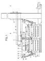
- the stacking device is used for stacking layers of crates 1 which are rectangular in plan with stacking corners 1 a running outwards for the position-safe reception of the crates inserted from above.
- the position consists of two longitudinal rows and three transverse rows of trays running at right angles to it.
- the stacking device is essentially composed of a base frame with a portal, in which a vertically movable lifting carriage 2 is guided.
- the lifting carriage 2 receives booms 3 which are movable in the horizontal direction on rollers with guideways in which a carriage 4 runs horizontally.
- An arrangement of holding elements 5 and 6 for the crates 1 is suspended on the carriage 4 and can be moved between a receiving point A and a delivery point B.
- the arrangement of holding elements consists of a row of individual folding surfaces 5, 6, which reach under the crates 1 in the area near the edge from two opposite sides and are pivoted jointly between a horizontal and vertical position for receiving or dispensing all crates of a layer.
- the folding surfaces 5, 6 end at the ends into diverging guide surfaces 5a, 6a, the inside dimension between the guide surfaces corresponding to the length of a tray, so that the trays are each surrounded by two interacting folding surfaces without play .
- the folding surfaces 5, 6 lying in series are arranged at a mutual distance from one another in such a way that a space for movement remains between adjacent guide surfaces 5a, 6a.
- actuating means for the folding surfaces and for the alignment elements described below are each provided on opposite sides, in the longitudinal as well as in the transverse direction. For reasons of simplicity, however, the following description essentially refers to the arrangement of the actuating means on only one side.
- the outer folding surfaces 5 are fastened to a common shaft 7, which is supported at the end in a pivot lever 12, which in turn is supported on a shaft 10 carried by side parts 11.
- the two side parts 11 are connected by a cross member 11a on which the carriage 4 is held.
- the inner folding surfaces 6 are each located on a shaft 16, 17, which are accommodated directly side by side by the side parts 11.
- the shafts 16, 17 have a small diameter, which consequently requires additional support.
- support bearings 18 are distributed on the cross member 11a between the sides at intervals over the wavelength share 11 provided.
- the folding surfaces 6 can also be arranged in a hinge-like manner on a common rotationally fixed shaft and pivoted about the rotationally fixed shaft via actuating means.
- the inner folding surfaces 6 receive their pivoting movement via a working cylinder 19, which is located on the side part 11 and actuates a U-shaped structural part 20 with its piston rod in the vertical plane, the arms of which are articulated on levers 21 on both sides.
- a further working cylinder 22 which is held in the side part 11, engages at a pivot point in the pivot lever 12 that is distant from the axis of rotation of the pivot lever 12. With the help of this working cylinder, the outer folding surfaces 5 carried by the pivot levers 12 can be pivoted by a defined distance to the center of the stacking device.
- crates 1 are pivoted towards the center of the stacking device by swiveling the vertical folding surfaces 5 located in the vertical position, and thus in the transverse direction via the cooperating divergent guide surfaces 5a, 6a of the respective folding surfaces 5, 6 see above as simultaneously aligned in the longitudinal direction via the folding surfaces 5, 6 themselves.
- the crates 1 assume the position shown in dash-dotted lines, bearing against the central support bearings 18.
- the stacking device is additionally provided with a device for pre-aligning with aligning elements 24, which act on opposite longitudinal sides on the respective previously deposited tray position before a subsequent layer of trays is released for stacking. This pre-alignment may be necessary if the trays are crooked due to a non-flat support surface.
- the alignment elements 24 have contact surfaces with angled, diverging guide surfaces 24a, the distance between the guide surfaces corresponding to the length of the riser layer.
- the movement of the alignment elements 24 mounted on the swivel levers 12 toward the center of the stacking device takes place via a working cylinder 25 which is arranged between the alignment element 24 and the shaft 10 with the interposition of a lever 26.
- the stacking device can also be provided with hold-down elements 27 which each extend over the row of trays and which can be lowered onto the trays 1 via working cylinders 28 with the task of pushing through the centering frames formed by the folding surfaces 5, 6 in the case of extremely light trays enable.
Landscapes
- Pile Receivers (AREA)
- Stacking Of Articles And Auxiliary Devices (AREA)
- Rigid Containers With Two Or More Constituent Elements (AREA)
Abstract
Description
Die Erfindung betrifft eine Vorrichtung zum vorzugsweise lagenweisen Ineinanderstapeln von im Grundriß rechteckigen Steigen od. dgl. mit nach außen hin verlaufenden Stapelecken zur lagesicheren Aufnahme einer von oben eingesetzten Steige, mit einer die einzelnen Steigen einer Lage von einander gegenüberliegenden Seiten untergreifenden und freigebenden Anordnung von Halteelementen, die zwischen einer Aufnahmestelle und einer Abgabestelle verfahrbar ist.The invention relates to a device for stacking layers of trays that are rectangular in plan or the like, with stacking corners that extend outwards, for the position-secure reception of a tray inserted from above, with an arrangement of holding elements that engages and releases the individual trays of a layer from opposite sides that can be moved between a receiving point and a delivery point.
Stapelvorrichtungen der genannten Art sind aus der Praxis bekannt. Die Anordnung von Halteelementen besteht aus die Steigen von gegenüberliegenden Seiten her untergreifenden äußeren Tragwinkeln sowie aus inneren Traghaken zwischen den Steigenreihen. Zum Aufnehmen bzw. Freigeben der Steigen führen die äußeren Tragwinkel eine Schwenkbewegung aus, während die inneren Traghaken zum Aufnehmen bzw. Freigeben der Steigen um 90° in der Horizontalebene verdreht werden. Tragwinkel und Traghaken sind dabei derart angeordnet, daß sie die Steigen im Bereich zwischen den Steigenecken untergreifen.Stacking devices of the type mentioned are known from practice. The arrangement of holding elements consists of the trays from under opposite outer support angles as well as inner support hooks between the rows of trays. To pick up or release the crates, the outer support brackets perform a swiveling movement, while the internal support hooks to pick up or release the crates are rotated by 90 ° in the horizontal plane. The support bracket and hook are arranged in such a way that they reach under the crates in the area between the crate corners.
Diese Stapelvorrichtungen arbeiten insofern nicht zufriedenstellend, als ein formschlüssiges Ineinandersetzen der Steigen nicht immer gewährleistet ist, was zu instabilen Steigenstapeln führt, wenn nicht ein manuelles Eingreifen erfolgt. Diese Unzulänglichkeit ist darauf zurückzuführen, daß die Ausrichtung der Steigen zueinander während ihres Transportes von der Aufnahmestelle zur Abgabestelle und während des Absetzens häufig verloren geht. Hinzu kommt, daß die Steigen vielfach aus einem labilen Material hergestellt sind und infolge dessen die Steigenecken nicht formstabil bleiben.These stacking devices do not work satisfactorily in that a form-fitting interlocking of the trays is not always guaranteed, which leads to unstable tray stacks unless manual intervention takes place. This inadequacy is due to the fact that the alignment of the trays with one another is often lost during their transport from the receiving point to the delivery point and during setting down. In addition, the crates are often made of an unstable material and, as a result, the crate corners do not remain dimensionally stable.
Die Aufgabe der Erfindung besteht darin eine Stapelvorrichtung der gattungsgemäßen Art zu schaffen, die bei einfacher Bauweise ein funktionssicheres Ineinanderstapeln der Steigen bei geringstmöglichem Abstand zwischen den Steigen sicherstellt. Darüber hinaus sollen mit der Stapelvorrichtung exakt ausgerichtete, stabile Steigenstapel gebildet werden.The object of the invention is to provide a stacking device of the generic type which, with a simple construction, ensures that the crates are stacked in a functionally reliable manner with the smallest possible distance between the crates. In addition, precisely aligned, stable crate stacks are to be formed with the stacking device.
Die Aufgabe wird erfindungsgemäß dadurch gelöst, daß die Halteelemente aus nebeneinanderliegenden einzelnen Klappflächen gebildet sind, die endseitig in die Steigen umschließende, divergierende Leitflächen übergehen, daß die Klappflächen gemeinsam um Drehachsen zwischen einer Horizontallage und einer Vertikallage zum Untergreifen und Freigeben der Steigen verschwenkbar sind und daß gegenüberliegende Klappflächen in der Vertikallage Zentrierrahmen für die abzusetzenden Steigen bilden, die beim Freigeben der Steigen in die Stapelecken der zuvor abgesetzten Steigen schwenken. Gemäß einem vorteilhaften Merkmal der Erfindung sind die außen liegenden Klappflächen zum gegenseitigen Ausrichten der Steigen in Längs- und Querrichtung in der Vertikallage zu den innen liegenden Klappflächen hin bewegbar.The object is achieved in that the holding elements are formed from juxtaposed individual folding surfaces, which at the end merge into diverging guiding surfaces surrounding the trays, that the folding surfaces can be pivoted together about axes of rotation between a horizontal position and a vertical position for reaching under and releasing the trays, and in that Opposing folding surfaces in the vertical position form a centering frame for the trays to be set down, which pivot when the trays are released into the stacking corners of the previously set down trays. According to an advantageous feature of the invention, the outer folding surfaces can be moved in the vertical position toward the inner folding surfaces for mutual alignment of the crates in the longitudinal and transverse directions.
Nachfolgend wird in den Zeichnungen die erfindungsgemäße Stapelvorrichtung anhand eines Ausführungsbeispiels näher erläutert. Es zeigen:
- Fig. 1 eine Ansicht der Stapelvorrichtung von der Seite;
- Fig. 2 eine Ansicht der Stapelvorrichtung von vorn;
- Fig. 3 die Klappflächen in vertikaler Ausrichtstellung;
- Fig. 4 die Klappflächen in horizontaler Haltestellung;
- Fig. 5 die Klappflächen in der Abgabe- und Zentrierstellung;
- Fig. 6 eine Ansicht auf die Steigenformation.
- Figure 1 is a side view of the stacking device.
- 2 shows a view of the stacking device from the front;
- 3 shows the folding surfaces in the vertical alignment position;
- 4 shows the folding surfaces in the horizontal holding position;
- Figure 5 shows the folding surfaces in the delivery and centering position.
- Fig. 6 is a view of the tray formation.
Die Stapelvorrichtung dient zum lagenweisen Ineinanderstapeln von im Grundriß rechteckigen Steigen 1 mit nach außen hin verlaufenden Stapelecken 1a zur lagesicheren Aufnahme der von oben eingesetzten Steigen.The stacking device is used for stacking layers of
Wie aus Fig. 6 ersichtlich, besteht im vorliegenden Fall die Lage aus zwei Längsreihen und aus rechtwinklig dazu verlaufenden drei Querreihen von Steigen.As can be seen from FIG. 6, in the present case the position consists of two longitudinal rows and three transverse rows of trays running at right angles to it.
Die Stapelvorrichtung setzt sich im wesentlichen zusammen aus einem Grundgestell mit einem Portal, in dem ein vertikal verfahrbarer Hubschlitten 2 geführt ist. Der Hubschlitten 2 seinerseits nimmt in Horizontalrichtung auf Laufrollen bewegbare Ausleger 3 auf mit Führungsbahnen, in denen ein Wagen 4 horizontal läuft. An dem Wagen 4 ist eine Anordnung von Halteelementen 5 und 6 für die Steigen 1 aufgehängt, die zwischen einer Aufnahmestelle A und einer Abgabestelle B verfahrbar ist.The stacking device is essentially composed of a base frame with a portal, in which a vertically
Die Anordnung von Halteelementen besteht aus in einer Reihe liegende einzelne Klappflächen 5, 6, die die Steigen 1 im randnahen Bereich jeweils von zwei einander gegenüberliegenden Seiten untergreifen und zur Aufnahme bzw. Abgabe aller Steigen einer Lage gemeinsam zwischen einer Horizontal- und Vertikallage verschwenkt werden. Wie aus Fig. 6 ersichtlich, gehen die Klappflächen 5, 6 endseitig in die Steigen umschließende, divergierende Leitflächen 5a, 6a über, wobei das Innenmaß zwischen den Leitflächen der Länge einer Steige entspricht, so daß die Steigen jeweils von zwei zusammenwirkenden Klappflächen spielfrei umgeben sind. Die in Reihe liegenden Klappflächen 5, 6 sind derart in gegenseitigem Abstand angeordnet, daß zwischen benachbarten Leitflächen 5a, 6a ein Bewegungsfreiraum verbleibt.The arrangement of holding elements consists of a row of
Wie die Zeichnungen veranschaulichen, sind Betätigungsmittel für die Klappflächen und für die nachfolgend beschriebenen Ausrichtelemente je auf gegenüberliegenden Seiten vorgesehen, und zwar in Längs- als auch in Querrichtung. Aus Gründen der Einfachheit wird in der nachfolgenden Beschreibung jedoch im wesentlich auf die Anordnung der Betätigungsmittel auf lediglich einer Seite Bezug genommen.As the drawings illustrate, actuating means for the folding surfaces and for the alignment elements described below are each provided on opposite sides, in the longitudinal as well as in the transverse direction. For reasons of simplicity, however, the following description essentially refers to the arrangement of the actuating means on only one side.
Die außen liegenden Klappflächen 5 sind an einer gemeinsamen Welle 7 befestigt, die endseitig in einem Schwenkhebel 12 gelagert ist, der seinerseits auf einer von Seitenteilen 11 getragenen Welle 10 gelagert ist. Die beiden Seitenteile 11 sind durch einen Querträger 11a verbunden, an dem der Wagen 4 gehaltert ist.The
Die innen liegenden Klappflächen 6 befinden sich jeweils auf einer Welle 16, 17, die unmittelbar nebeneinanderliegend von den Seitenteilen 11 aufgenommen sind. Um den Abstand zwischen den beiden Steigenreihen so gering als möglich zu halten, weisen die Wellen 16, 17 einen geringen Durchmesser auf, was infolgedessen eine zusätzliche Abstützung erforderlich macht. Hierzu sind in Abständen über die Wellenlänge verteilt Traglager 18 am Querträger 11a zwischen den Seiten teilen 11 vorgesehen. In einer abgewandelten Ausführungsform können die Klappflächen 6 auch scharnierartig auf einer gemeinsamen drehfesten Welle angeordnet sein und über Betätigungsmittel um die drehfeste Welle verschwenkt werden.The
Wie die Figur 1 erkennen läßt, bilden die außen liegenden Klappflächen 5 mit der Schwenkwelle 7 und einem kurzen Hebel 8 eine starre Baueinheit, an die endseitig der Welle 7 ein vom Schwenkhebel 12 getragener Arbeitszylinder 13 angreift, über den die Klappflächen zwischen ihrer Vertikal- und Horizontallage verschwenkt werden.As can be seen in FIG. 1, the
Entsprechend dazu erhalten die innenliegenden Klappflächen 6 ihre Schwenkbewegung über einen Arbeitszylinder 19, der sich an dem Seitenteil 11 befindet und mit seiner Kolbenstange ein U-förmiges Konstruktionsteil 20 in vertikaler Ebene betätigt, dessen beidseitige Ausleger an Hebeln 21 angelenkt sind. Letztere bilden mit den innenliegenden Klappflächen 6 und den Schwenkwellen 16, 17 eine starre Baueinheit.Correspondingly, the
An einem von der Drehachse des Schwenkhebels 12 entfernt liegenden Anlenkpunkt im Schwenkhebel 12 greift ein weiterer Arbeitszylinder 22 an, der im Seitenteil 11 gehaltert ist. Mit Hilfe dieses Arbeitszylinders lassen sich die von den Schwenkhebeln 12 getragenen außen liegenden Klappflächen 5 um eine definierte Wegstrecke zur Mitte der Stapelvorrichtung hin schwenken.A further working
Die der Aufnahmestelle A von nicht dargestellten Transporteuren auf Zufuhrbahnen 23 in zwei nebeneinanderliegenden Reihen zugeführten, zu einer Lage bereitgestellten Steigen 1 werden durch Heranschwenken der sich in Vertikalstellung befindenden außenliegenden Klappflächen 5 über die Arbeitszylinder 22 zur Mitte der Stapelvorrichtung hin verschoben und somit in Querrichtung über die zusammenwirkenden divergierenden Leitflächen 5a, 6a der jeweiligen Klappflächen 5, 6 so wie gleichzeitig in Längsrichtung über die Klappflächen 5, 6 selbst ausgerichtet. Wie anhand der Figur 3 verdeutlicht, nehmen die Steigen 1 nach dem Verschieben von den beiden Seiten zur Mitte hin und damit nach dem Ausrichtvorgang die strichpunktiert dargestellte Position unter Anlage an den mittigen Traglagern 18 ein.The receptacle A from feeders (not shown) on
Mit der Schwenkbewegung der Klappflächen 5, 6 aus der Vertikal- in die Horizontallage, ausgeführt über die Arbeitszylinder 13, werden alle Steigen einer Lage gemeinsam aufgenommen, wie Figur 4 zeigt, und zur Abgabestelle B über eine zuvor abgesetzte Steigenlage gebracht sowie bis auf einen definierten Abstand zur unteren Lage abgesenkt. Der Abstand zwischen der bereits abgesetzten Lage zur abzusetzenden Lage ist dabei derart gewählt, daß sich die die Steigen tragenden Klappflächen 5, 6 mit Leitflächen 5a, 6a nach dem Zurückschwenken zur Freigabe der Steigen aus der Horizontallage in die Vertikallage in die Stapelecken der zuvor abgesetzten Steige legen und somit Zentrierrahmen für die freikommenden Steigen bilden, siehe Figur 5, was ein formschlüssiges Ineinanderstapeln der Steigen gewährleistet.With the swiveling movement of the
Die erfindungsgemäße Stapelvorrichtung ist zusätzlich mit einer Einrichtung zum Vorausrichten versehen mit Ausrichtelementen 24, die von gegenüberliegenden Längsseiten auf die jeweils zuvor abgesetzte Steigenlage einwirken, bevor eine folgende Lage von Steigen zum Stapeln freigegeben wird. Dieses Vorausrichten kann unter Umständen erforderlich sein, wenn aufgrund einer nicht ebenen Auflagefläche die Steigen schief stehen. Die Ausrichtelemente 24 besitzen Anlageflächen mit abgewinkelten, divergierenden Leitflächen 24a, wobei der Abstand zwischen den Leitflächen der Länge der Steigenlage entspricht. Die Bewegung der an den Schwenkhebeln 12 gelagerten Ausrichtelemente 24 zur Mitte der Stapelvorrichtung hin erfolgt über einen Arbeitszylinder 25, der zwischen dem Ausrichtelement 24 und der Welle 10 unter Zwischenschaltung eines Hebels 26 angeordnet ist.The stacking device according to the invention is additionally provided with a device for pre-aligning with aligning
Letztlich kann die Stapelvorrichtung noch mit Niederhalteelementen 27 versehen sein, die sich je über die Steigenreihe erstrecken und die über Arbeitszylinder 28 auf die Steigen 1 absenkbar sind mit der Aufgabe, bei extrem leichten Steigen ein Durchschieben durch die von den Klappflächen 5, 6 gebildeten Zentrierrahmen zu ermöglichen.Ultimately, the stacking device can also be provided with hold-down
Claims (6)
Applications Claiming Priority (2)
| Application Number | Priority Date | Filing Date | Title |
|---|---|---|---|
| DE3837413A DE3837413A1 (en) | 1988-11-04 | 1988-11-04 | DEVICE FOR STACKING RISES |
| DE3837413 | 1988-11-04 |
Publications (2)
| Publication Number | Publication Date |
|---|---|
| EP0366943A1 true EP0366943A1 (en) | 1990-05-09 |
| EP0366943B1 EP0366943B1 (en) | 1992-11-11 |
Family
ID=6366460
Family Applications (1)
| Application Number | Title | Priority Date | Filing Date |
|---|---|---|---|
| EP89118169A Expired - Lifetime EP0366943B1 (en) | 1988-11-04 | 1989-09-30 | Device for stacking crates onto each other |
Country Status (2)
| Country | Link |
|---|---|
| EP (1) | EP0366943B1 (en) |
| DE (2) | DE3837413A1 (en) |
Cited By (5)
| Publication number | Priority date | Publication date | Assignee | Title |
|---|---|---|---|---|
| US5263813A (en) * | 1989-12-11 | 1993-11-23 | Steinle Maschinenfabrik Gmbh | Apparatus having a gripping mechanism for the stacking and unstacking of containers |
| EP1285870A1 (en) * | 2001-07-23 | 2003-02-26 | FPS Food Processing Systems B.V. | Gripper device |
| WO2009018895A1 (en) * | 2007-08-06 | 2009-02-12 | Khs Ag | Method for unstacking or stacking packages and device for performing said method |
| ITUA20163512A1 (en) * | 2016-05-17 | 2017-11-17 | Co M A N S R L | Machine and method for stacking product containment baskets |
| CN114735482A (en) * | 2022-03-31 | 2022-07-12 | 广东电网有限责任公司广州供电局 | Based on intelligent recognition sign indicating number equipment of breaking a jam |
Families Citing this family (3)
| Publication number | Priority date | Publication date | Assignee | Title |
|---|---|---|---|---|
| DE4033587A1 (en) * | 1990-10-22 | 1992-04-23 | Focke & Co | DEVICE FOR HANDLING ITEMS LIKE CARDBOARDS |
| DE4338801A1 (en) * | 1993-11-13 | 1995-05-18 | Thomas A Ahbel | Method of stacking piece goods of different sizes and/ quality |
| IT202100021458A1 (en) * | 2021-08-06 | 2023-02-06 | System Logistics S P A | Cassette pick-up device |
Citations (1)
| Publication number | Priority date | Publication date | Assignee | Title |
|---|---|---|---|---|
| US4592692A (en) * | 1984-02-23 | 1986-06-03 | Okura Yusoki Kabushiki Kaisha | Pallet loading apparatus |
Family Cites Families (6)
| Publication number | Priority date | Publication date | Assignee | Title |
|---|---|---|---|---|
| DE1201523B (en) * | 1962-03-28 | 1965-09-23 | Hans Lingl | Gripping device for stacked goods, such as building materials, etc. |
| US3468436A (en) * | 1967-07-07 | 1969-09-23 | Sun Drop Bottling Co Inc | Machine for palletizing soft drink cases |
| DE6942953U (en) * | 1969-11-04 | 1970-04-23 | Wilhelm Becker & Co G M B H Fa | DEVICE FOR HORIZONTAL STACKING OF CONCRETE SLABS |
| GB1442301A (en) * | 1972-07-13 | 1976-07-14 | Redland Tiles Ltd | Clamps and vehicles therefor |
| DE2733985B2 (en) * | 1977-07-28 | 1980-04-03 | Enzinger-Union-Werke Ag, 6800 Mannheim | Device for loading and unloading palletized containers in layers, in particular barrels |
| DD145257A1 (en) * | 1979-09-07 | 1980-12-03 | Harald Jesch | GRIPPERS FOR MACHINING AND UNPALETTING, ESPECIALLY BOTTLE COSTS |
-
1988
- 1988-11-04 DE DE3837413A patent/DE3837413A1/en not_active Ceased
-
1989
- 1989-09-30 EP EP89118169A patent/EP0366943B1/en not_active Expired - Lifetime
- 1989-09-30 DE DE8989118169T patent/DE58902699D1/en not_active Expired - Fee Related
Patent Citations (1)
| Publication number | Priority date | Publication date | Assignee | Title |
|---|---|---|---|---|
| US4592692A (en) * | 1984-02-23 | 1986-06-03 | Okura Yusoki Kabushiki Kaisha | Pallet loading apparatus |
Cited By (8)
| Publication number | Priority date | Publication date | Assignee | Title |
|---|---|---|---|---|
| US5263813A (en) * | 1989-12-11 | 1993-11-23 | Steinle Maschinenfabrik Gmbh | Apparatus having a gripping mechanism for the stacking and unstacking of containers |
| EP1285870A1 (en) * | 2001-07-23 | 2003-02-26 | FPS Food Processing Systems B.V. | Gripper device |
| WO2009018895A1 (en) * | 2007-08-06 | 2009-02-12 | Khs Ag | Method for unstacking or stacking packages and device for performing said method |
| US9302858B2 (en) | 2007-08-06 | 2016-04-05 | Khs Gmbh | Method for handling packages in a beverage bottling plant, a method for unstacking packages in a container filling plant, a method for stacking packages in a container filling plant, and arrangements for accomplishing the methods |
| ITUA20163512A1 (en) * | 2016-05-17 | 2017-11-17 | Co M A N S R L | Machine and method for stacking product containment baskets |
| WO2017199161A1 (en) * | 2016-05-17 | 2017-11-23 | Co.M.A.N. S.R.L. | Machine and method for stacking crates for containing products |
| CN114735482A (en) * | 2022-03-31 | 2022-07-12 | 广东电网有限责任公司广州供电局 | Based on intelligent recognition sign indicating number equipment of breaking a jam |
| CN114735482B (en) * | 2022-03-31 | 2023-10-20 | 广东电网有限责任公司广州供电局 | Based on intelligent identification equipment of destacking |
Also Published As
| Publication number | Publication date |
|---|---|
| DE58902699D1 (en) | 1992-12-17 |
| EP0366943B1 (en) | 1992-11-11 |
| DE3837413A1 (en) | 1990-05-10 |
Similar Documents
| Publication | Publication Date | Title |
|---|---|---|
| EP0377398B1 (en) | Robot for palletising | |
| DE3908496C2 (en) | Handling device for a bending machine, method for reversing the position of a workpiece in a bending process and bending machine | |
| EP0541744B1 (en) | Stacking process and device | |
| DE3520084C2 (en) | Pipe handling system | |
| DE2444124C3 (en) | Additional device for the automatic loading and / or unloading of machine tools | |
| EP0494404A1 (en) | Plate feed apparatus for plate-dividing saws | |
| DE2846785B1 (en) | Device for automatically filling the edge joints of double or multiple insulating glass panes with a sealant using filling nozzles | |
| DE2512613C2 (en) | Suction gripping device for gripping and handling a cuboid body | |
| DE3515729C2 (en) | ||
| EP0366943B1 (en) | Device for stacking crates onto each other | |
| EP0436506A1 (en) | Device for squaring-up piles | |
| DE4024450A1 (en) | DEVICE FOR LOADING PACKING MACHINES WITH STACKS OF LAYERED MATERIAL | |
| WO1998014288A1 (en) | Processing machine | |
| DE2236188B2 (en) | Conveyor | |
| CH618939A5 (en) | ||
| DD159617A1 (en) | DEVICE FOR RECEIVING AND HANDLING FLAT STACKABLE OBJECTS | |
| EP0489681B1 (en) | Method and apparatus for moving closely juxtaposed stacked strips or panel shaped workpieces on a low friction work support surface | |
| CH634492A5 (en) | METHOD AND DEVICE FOR SEPARATING LENGTHED WIRE FORMING A LOOSE BUNDLE, IN PARTICULAR PURPOSE OF WIRE FEEDING TO A GRID WELDING MACHINE. | |
| DE3317303C3 (en) | Straightening table | |
| EP0075158B1 (en) | Tool for washing the exposed surfaces of freshly pressed concrete plates with exposed aggregate | |
| DE2155455C3 (en) | Device for the automatic lifting and stacking of planks | |
| DE2614009A1 (en) | Piece goods handling mechanism - has outermost grab jaws moving together to engage with items on both sides | |
| DE2559316A1 (en) | Plate itemiser from stack - has plate removed from pile to transfer point by series of driving arms | |
| EP3725705B1 (en) | Container changing device | |
| AT410660B (en) | STACK DEVICE |
Legal Events
| Date | Code | Title | Description |
|---|---|---|---|
| PUAI | Public reference made under article 153(3) epc to a published international application that has entered the european phase |
Free format text: ORIGINAL CODE: 0009012 |
|
| AK | Designated contracting states |
Kind code of ref document: A1 Designated state(s): BE DE FR GB IT NL SE |
|
| RAP1 | Party data changed (applicant data changed or rights of an application transferred) |
Owner name: LEIFELD & LEMKE MASCHINENFABRIK GMBH & CO. KG |
|
| RAP1 | Party data changed (applicant data changed or rights of an application transferred) |
Owner name: LEIFELD & LEMKE MASCHINENFABRIK GMBH & CO. KG |
|
| 17P | Request for examination filed |
Effective date: 19901009 |
|
| 17Q | First examination report despatched |
Effective date: 19920430 |
|
| ITF | It: translation for a ep patent filed |
Owner name: STUDIO INGG. FISCHETTI & WEBER |
|
| GRAA | (expected) grant |
Free format text: ORIGINAL CODE: 0009210 |
|
| AK | Designated contracting states |
Kind code of ref document: B1 Designated state(s): BE DE FR GB IT NL SE |
|
| GBT | Gb: translation of ep patent filed (gb section 77(6)(a)/1977) | ||
| REF | Corresponds to: |
Ref document number: 58902699 Country of ref document: DE Date of ref document: 19921217 |
|
| ET | Fr: translation filed | ||
| PGFP | Annual fee paid to national office [announced via postgrant information from national office to epo] |
Ref country code: FR Payment date: 19930825 Year of fee payment: 6 |
|
| PLBE | No opposition filed within time limit |
Free format text: ORIGINAL CODE: 0009261 |
|
| STAA | Information on the status of an ep patent application or granted ep patent |
Free format text: STATUS: NO OPPOSITION FILED WITHIN TIME LIMIT |
|
| 26N | No opposition filed | ||
| REG | Reference to a national code |
Ref country code: FR Ref legal event code: ST |
|
| PGFP | Annual fee paid to national office [announced via postgrant information from national office to epo] |
Ref country code: SE Payment date: 19940826 Year of fee payment: 6 |
|
| PGFP | Annual fee paid to national office [announced via postgrant information from national office to epo] |
Ref country code: BE Payment date: 19940909 Year of fee payment: 6 |
|
| PGFP | Annual fee paid to national office [announced via postgrant information from national office to epo] |
Ref country code: GB Payment date: 19940929 Year of fee payment: 6 |
|
| PGFP | Annual fee paid to national office [announced via postgrant information from national office to epo] |
Ref country code: NL Payment date: 19940930 Year of fee payment: 6 |
|
| REG | Reference to a national code |
Ref country code: FR Ref legal event code: R1 |
|
| REG | Reference to a national code |
Ref country code: FR Ref legal event code: D1 |
|
| EAL | Se: european patent in force in sweden |
Ref document number: 89118169.5 |
|
| PG25 | Lapsed in a contracting state [announced via postgrant information from national office to epo] |
Ref country code: GB Effective date: 19950930 Ref country code: BE Effective date: 19950930 |
|
| PG25 | Lapsed in a contracting state [announced via postgrant information from national office to epo] |
Ref country code: SE Effective date: 19951001 |
|
| BERE | Be: lapsed |
Owner name: LEIFELD & LEMKE MASCHINENFABRIK G.M.B.H. & CO. K Effective date: 19950930 |
|
| PG25 | Lapsed in a contracting state [announced via postgrant information from national office to epo] |
Ref country code: NL Effective date: 19960401 |
|
| GBPC | Gb: european patent ceased through non-payment of renewal fee |
Effective date: 19950930 |
|
| PG25 | Lapsed in a contracting state [announced via postgrant information from national office to epo] |
Ref country code: FR Effective date: 19960531 |
|
| NLV4 | Nl: lapsed or anulled due to non-payment of the annual fee |
Effective date: 19960401 |
|
| EUG | Se: european patent has lapsed |
Ref document number: 89118169.5 |
|
| REG | Reference to a national code |
Ref country code: FR Ref legal event code: ST |
|
| PGFP | Annual fee paid to national office [announced via postgrant information from national office to epo] |
Ref country code: DE Payment date: 20021128 Year of fee payment: 14 |
|
| PG25 | Lapsed in a contracting state [announced via postgrant information from national office to epo] |
Ref country code: DE Free format text: LAPSE BECAUSE OF NON-PAYMENT OF DUE FEES Effective date: 20040401 |
|
| PG25 | Lapsed in a contracting state [announced via postgrant information from national office to epo] |
Ref country code: IT Free format text: LAPSE BECAUSE OF NON-PAYMENT OF DUE FEES Effective date: 20050930 |