EP0365192B1 - Improvements in continuous business forms assemblies - Google Patents
Improvements in continuous business forms assemblies Download PDFInfo
- Publication number
- EP0365192B1 EP0365192B1 EP89310301A EP89310301A EP0365192B1 EP 0365192 B1 EP0365192 B1 EP 0365192B1 EP 89310301 A EP89310301 A EP 89310301A EP 89310301 A EP89310301 A EP 89310301A EP 0365192 B1 EP0365192 B1 EP 0365192B1
- Authority
- EP
- European Patent Office
- Prior art keywords
- web
- adhesive
- mailer
- webs
- assembly according
- Prior art date
- Legal status (The legal status is an assumption and is not a legal conclusion. Google has not performed a legal analysis and makes no representation as to the accuracy of the status listed.)
- Expired - Lifetime
Links
Images


Classifications
-
- B—PERFORMING OPERATIONS; TRANSPORTING
- B42—BOOKBINDING; ALBUMS; FILES; SPECIAL PRINTED MATTER
- B42D—BOOKS; BOOK COVERS; LOOSE LEAVES; PRINTED MATTER CHARACTERISED BY IDENTIFICATION OR SECURITY FEATURES; PRINTED MATTER OF SPECIAL FORMAT OR STYLE NOT OTHERWISE PROVIDED FOR; DEVICES FOR USE THEREWITH AND NOT OTHERWISE PROVIDED FOR; MOVABLE-STRIP WRITING OR READING APPARATUS
- B42D5/00—Sheets united without binding to form pads or blocks
- B42D5/02—Form sets
- B42D5/023—Continuous form sets
- B42D5/025—Mailer assemblies
- B42D5/026—Mailer assemblies with return letter or return card
Definitions
- This invention has reference to continuous business forms assemblies which are subsequently processed to become a self mailer piece and has particular reference to continuous business forms assemblies comprising a plurality of individual business forms in continuous format.
- business forms in the field of such self mailer business forms assemblies it is known to use business forms as a continuous assembly capable of being processed including separating the web into form lengths to form a plurality of self mailer pieces which assembly is in two parts either as a single web folded longitudinally at about its longitudinal centre line or as two separate continuous web parts collated together and with heat seal adhesive so that when the collated forms construction is passed through a heat seal mechanism and divided into mailer lengths the two parts form a simple self mailer piece.
- British Patent No 1249054 other examples are described in British Specification No 1564423.
- Another example is described in the Specification of European Patent Application No 0143622.
- US Specification US-A-3982746 describes a self contained direct mailing booklet including personalized information such as a name and address.
- personalized information such as a name and address.
- the portions of the booklet containing the personalized information may be readily removed from the booklet and placed in the mail to indicate acceptance of an offer set forth in the booklet.
- a continuous business forms assembly comprises a continuous business form assembly comprising three, longitudinally extending, webs intended to be assembled together as a first outer web, a second inner web and a third outer web, each web being similarly divided by lines of perforation into a plurality of mailer lengths, first activatable adhesive located along the edges of each mailer length of at least one of the two outer webs such that the first adhesive can be activated to seal the edges together to form a sealed mailer, second adhesive located in three strips on each mailer length between one of the outer webs and the inner web, the second adhesive securing or being activatable to secure the inner web to said one of the outer webs to form a return envelope, and characterised in that each mailer length of the inner web has a detachable flap bearing an activatable adhesive on one side, and divided into a plurality of portions by tear-off perforations, and each of the portions bearing, on its other side, a printed address of an intended receptor of the return envelope, the addresses on different portions being different
- a continuous business forms assembly comprises three webs 2, 3, 4 to be collated together.
- Each one of the three webs has a set of feed apertures 5 in its margin (the web 3 has feed apertures on one side margin only) to ensure accurate collation of the webs 2, 3, 4.
- Each web is divided into form lengths by lines of cross perforations 6.
- Longitudinal lines of marginal perforations 7 are provided in each of the webs 2 and 4 at each of their side margins to enable a detachable margin 8 to be provided.
- the web 3 has a line of marginal tear off perforations 7 at one side margin only.
- the assembly comprising the webs 2, 3, 4 of which the first web 2 carries on its rear face (but for the sake of clarity is not shown in dotted lines) longitudinal lines 9 of heat seal adhesive positioned adjacent to the longitudinal lines 7 of tear off perforations and with the heat seal lines 9 within the side margins 8 so that the heat seal margins may be readily detached.
- a line of cross perforations 10 is provided between the longitudinal lines of perforations 7 within each respective form length.
- a line 11 of longitudinal perforations is provided between the line of cross perforations 10 and one of the lines of cross perforations 6 dividing the web into form lengths.
- the lines 10, 11 of tear off perforations are provided in order that parts of the form may be detached and used as will be hereinafter described.
- Lines 12 of peel apart areas of glue adhesive dots are provided on the rear face of the web 2 (shown in full lines of the sake of clarity) on each side of each of the transverse lines of cross perforations 6.
- the areas of adhesive are made up of small dots arranged in lines transverse to the longitudinal direction of the web. This pattern of peel apart glue adhesive enables ready separation of for example sheets of paper secured together and yet normally provide a satisfactory securing means. However the number and size of the dots must not be so great as to firmly secure the sheets together permanently.
- the lines 12 of peel apart areas of glue extend between the longitudinal lines 7 of perforations except that a gap is provided in the areas of glue to provide an unglued part to accommodate for the receipt of the flap 15 (to be hereafter described) of the other envelope part shown in Fig.
- each form length of the web 2 an aperture covered by a transparent patch provides a window 16 through which the address of the receptor of the envelope may be viewed. Provision is made at 17 for receipt of a stamp or prestamped or franked postage paid imprint.
- the web 3 is intended to be collated with web 4 and secured to this web to form a return envelope pocket part in each form length. Then collating with the web 2 may be effected.
- Lines of longitudinal perforations 13 are provided in the web 3 and a line of transverse perforations 14 is provided between the lines of perforations 13 and the edge of the web away from the margin 8 to define a flap part 15.
- the areas of printing 15a are provided in each of the flap parts of the web 3. These areas of printing 15a each bear a respective address as shown diagrammatically at Figs. 2 and 5.
- the line 13 of longitudinal perforations provides the detachable flap part 15 of the envelope and the body part of each form length of the web 3 has an area 19 to receive one of the detachable flap parts 15.
- the flap 15 has on part of its rear face (on the back of the flap as shown in Fig 4) a coating of gum. It is intended that the part of the flap bearing the address to which a reply is to be sent is detached and adhered as an address label to the part 19 of the web 3.
- the area 15 to which the gum coating is applied extends beyond the perforation line 13 to an area 20 to be used for sealing the pocket created by the web parts 3 and 4.
- the area 19a bears printed information for the eventual recipient for dealing with the envelope and its contents.
- the web 4 is divided into portions by a line 21 of longitudinal perforations. It is arranged that the line 21 of longitudinal perforations will be in register with the line 13 of longitudinal perforations as shown in Fig 2 when webs 2 and 3 are in register.
- the part of web 4 between the transverse lines of perforations 6 (forming the perforations to divide the web 4 into envelope lengths) and between the line of perforations 13 and the adjacent margin is provided with two transverse lines 22 of adhesive and one longitudinal line 23 of adhesive.
- the lines of adhesive 22 and 23 enable pockets 24 to be formed by the form length parts of the webs 3 and 4. It is preferred that these lines of adhesive 22, 23 are of cold application pattern adhesive.
- Each form length of the web 4 bears printed information 19a, 20a. In particular the area 19a of the form has printed information about how the form is to be processed and explains what action should be taken by the recipient.
- FIG 5 shows a detached and heat sealed assembly in which the web part 2 has been removed and shows the web envelope lengths sealed together and one of the flap part areas 15 bearing an area of printing 15a about to be detached and placed on the area 19 utilizing the gum coating on the rear face of the flap part 15.
- Fig 6 is a view similar to Fig 5 with the top part (as shown in Fig 5) of the web 4 detached leaving the pocket constructed from the form lengths of the webs 3 and 4.
- the business forms assembly as shown in the drawings is primarily intended for use by the police and traffic warden services in dealing with traffic and other offences committed by members of the public but similar forms may be suitable for other applications.
- the assembly is produced from three webs as shown in Figs 1, 2 and 3.
- the webs are collated and secured together by the lines of adhesive 9, 12, 22, and 23 as well as the line of peel apart glue 12.
- a notification of the offence is sent to the offender by filling in the offenders address at 20a (Fig 3).
- This notification is in the form of a single form length of the assembly described and comprising form lengths of the webs 2, 3 and 4 secured together, and bears information as at 19a (Fig 3) about the offence and details of how to deal with the documentation.
- the offender receives the notification and he removes the uppermost sheet (a form length of the web 2) by tearing off the margins 8 along lines 7 and then peeling apart the uppermost sheet. This is possible because of the use of the peel apart adhesive.
- the offender then has the alternative of paying a fine and inserting this in the pocket (for example by cheque) and detaching one of the flap parts 15 designating an address to enable the envelope consisting of the pocket to be sent to the police.
- the offender may wish to appeal to the Court in which case he marks the form accordingly by detaching one of the portions defined by the tear off perforations 10 and 11 (Fig 1) indicating that he wishes to appeal and enclosing this in the envelope.
- the offender detaches the address of the police and sends his appeal to the police where it is dealt with.
- the envelope is closed by moistening the area 20 of gum coating.
- the borders of the envelope as shown in Fig 6 may bear lines of perforations within areas of heat seal to enable the margin of the envelope to be removed.
- the lines 22, 23 of adhesive may be of hot melt adhesive and the webs 3 and 4 be collated and secured together to form a continuous envelope assembly and the web 2 may be secured to the secured together webs 3 and 4 subsequently.
- the combined webs 3 and 4 may be separated into envelope lengths and secured to detached form lengths of the web 2 by passing the sheets through a heat sealing machine.
- business forms assembly may be used for applications other than the processing of documents by police etc. for example for another application where a recipient of a document has to determine the destination of a document and despatch it.
- the assembly may have arrangements of perforation lines (similar to the lines of perforation 13, 14 shown on the drawings) to provide three (or more) detachable and sealable parts of the form. Such assemblies may be used when a choice from three (or more) selections may be made and a notification of such selections is to be communicated.
Abstract
Description
- This invention has reference to continuous business forms assemblies which are subsequently processed to become a self mailer piece and has particular reference to continuous business forms assemblies comprising a plurality of individual business forms in continuous format. In the field of such self mailer business forms assemblies it is known to use business forms as a continuous assembly capable of being processed including separating the web into form lengths to form a plurality of self mailer pieces which assembly is in two parts either as a single web folded longitudinally at about its longitudinal centre line or as two separate continuous web parts collated together and with heat seal adhesive so that when the collated forms construction is passed through a heat seal mechanism and divided into mailer lengths the two parts form a simple self mailer piece. One example of such an assembly is described in the Specification of British Patent No 1249054, other examples are described in British Specification No 1564423. Another example is described in the Specification of European Patent Application No 0143622.
- Also US Specification US-A-3982746 describes a self contained direct mailing booklet including personalized information such as a name and address. The portions of the booklet containing the personalized information may be readily removed from the booklet and placed in the mail to indicate acceptance of an offer set forth in the booklet.
- It is also the practice of some sales companies to circulate mail to customers which invites the customer to reply usually accepting an offer by the sales company to partake of an offer made by the company. Very often the customer has a choice and sometimes the making of such a choice entails the sending of a reply to an accepted address being one of several addresses and this has entailed the entry of an address on an accompanying envelope. There are also other situations which require a document to be sent to a recipient who has to determine the destination of the return document and despatch it.
- It is also the proposed practice of Police (or Traffic Wardens) in certain parts of the United Kingdom to issue to members of the public who infringe traffic or parking laws certain documents which are required to be processed by the recipient. These documents refer to certain traffic offences for which the offender is presented with a document referring to such offence. The document contains information about the infringement complained of and information about processing the document. In particular the infringer has, for example, to decide whether to pay a fine or whether to appeal against the objections issued. In the processing of such documents the police do not wish to deal with fines but they wish to be advised that the recipient of the document wishes to appeal against the objection referred to in the document.
- It is an object of the present invention to provide an improved continuous business forms assembly which is for example particularly suitable for enabling the form being part of the assembly to be readily processed to enable a document which is part of the assembly to be despatched to a selected destination.
- According to the present invention a continuous business forms assembly comprises a continuous business form assembly comprising three, longitudinally extending, webs intended to be assembled together as a first outer web, a second inner web and a third outer web, each web being similarly divided by lines of perforation into a plurality of mailer lengths, first activatable adhesive located along the edges of each mailer length of at least one of the two outer webs such that the first adhesive can be activated to seal the edges together to form a sealed mailer, second adhesive located in three strips on each mailer length between one of the outer webs and the inner web, the second adhesive securing or being activatable to secure the inner web to said one of the outer webs to form a return envelope, and characterised in that each mailer length of the inner web has a detachable flap bearing an activatable adhesive on one side, and divided into a plurality of portions by tear-off perforations, and each of the portions bearing, on its other side, a printed address of an intended receptor of the return envelope, the addresses on different portions being different from one another, whereby the recipient of the mailer may determine the destination of the return envelope.
- A continuous business forms assembly according to the present invention will now be described by way of example with reference to the accompanying drawings wherein:
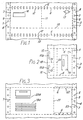
- Figs. 1 and 3 are views of parts of the three constituent webs of the assembly of which
- Fig. 1 is a view of the top face of the first web
- Fig. 2 is a view of the top face of the second web and
- Fig. 3 is a view of the under face of one envelope length of the third web.
- Fig. 4 shows two of the webs shown in Figs. 1 and 3 being moved into register position.
- Fig. 5 shows a part of the assembly in use and
- Fig. 6 is a view of part of the assembly being used as an envelope assembly.
- As shown in Figs. 1, 2 and 3 of the drawings a continuous business forms assembly comprises three
webs feed apertures 5 in its margin (theweb 3 has feed apertures on one side margin only) to ensure accurate collation of thewebs cross perforations 6. Longitudinal lines ofmarginal perforations 7 are provided in each of thewebs 2 and 4 at each of their side margins to enable adetachable margin 8 to be provided. Theweb 3 has a line of marginal tear offperforations 7 at one side margin only. - The assembly comprising the
webs first web 2 carries on its rear face (but for the sake of clarity is not shown in dotted lines) longitudinal lines 9 of heat seal adhesive positioned adjacent to thelongitudinal lines 7 of tear off perforations and with the heat seal lines 9 within theside margins 8 so that the heat seal margins may be readily detached. A line of cross perforations 10 is provided between the longitudinal lines ofperforations 7 within each respective form length. Aline 11 of longitudinal perforations is provided between the line of cross perforations 10 and one of the lines ofcross perforations 6 dividing the web into form lengths. - The
lines 10, 11 of tear off perforations are provided in order that parts of the form may be detached and used as will be hereinafter described. -
Lines 12 of peel apart areas of glue adhesive dots are provided on the rear face of the web 2 (shown in full lines of the sake of clarity) on each side of each of the transverse lines ofcross perforations 6. The areas of adhesive are made up of small dots arranged in lines transverse to the longitudinal direction of the web. This pattern of peel apart glue adhesive enables ready separation of for example sheets of paper secured together and yet normally provide a satisfactory securing means. However the number and size of the dots must not be so great as to firmly secure the sheets together permanently. Thelines 12 of peel apart areas of glue extend between thelongitudinal lines 7 of perforations except that a gap is provided in the areas of glue to provide an unglued part to accommodate for the receipt of the flap 15 (to be hereafter described) of the other envelope part shown in Fig. 2 when thewebs web 2 an aperture covered by a transparent patch provides awindow 16 through which the address of the receptor of the envelope may be viewed. Provision is made at 17 for receipt of a stamp or prestamped or franked postage paid imprint. - As shown in Fig 2 the
web 3 is intended to be collated with web 4 and secured to this web to form a return envelope pocket part in each form length. Then collating with theweb 2 may be effected. Lines of longitudinal perforations 13 are provided in theweb 3 and a line of transverse perforations 14 is provided between the lines of perforations 13 and the edge of the web away from themargin 8 to define aflap part 15. The areas ofprinting 15a are provided in each of the flap parts of theweb 3. These areas ofprinting 15a each bear a respective address as shown diagrammatically at Figs. 2 and 5. The line 13 of longitudinal perforations provides thedetachable flap part 15 of the envelope and the body part of each form length of theweb 3 has anarea 19 to receive one of thedetachable flap parts 15. Theflap 15 has on part of its rear face (on the back of the flap as shown in Fig 4) a coating of gum. It is intended that the part of the flap bearing the address to which a reply is to be sent is detached and adhered as an address label to thepart 19 of theweb 3. Thearea 15 to which the gum coating is applied extends beyond the perforation line 13 to anarea 20 to be used for sealing the pocket created by theweb parts 3 and 4. Thearea 19a bears printed information for the eventual recipient for dealing with the envelope and its contents. As shown in Fig 3 the web 4 is divided into portions by aline 21 of longitudinal perforations. It is arranged that theline 21 of longitudinal perforations will be in register with the line 13 of longitudinal perforations as shown in Fig 2 whenwebs - The part of web 4 between the transverse lines of perforations 6 (forming the perforations to divide the web 4 into envelope lengths) and between the line of perforations 13 and the adjacent margin is provided with two
transverse lines 22 of adhesive and onelongitudinal line 23 of adhesive. The lines of adhesive 22 and 23 enablepockets 24 to be formed by the form length parts of thewebs 3 and 4. It is preferred that these lines ofadhesive information 19a, 20a. In particular thearea 19a of the form has printed information about how the form is to be processed and explains what action should be taken by the recipient. - Referring to Fig 4 there is shown a part of the
webs web 3 is positioned over part of a web 4 before being collated with theweb 2 then detached into forms lengths and heat sealed. - Likewise Fig 5 shows a detached and heat sealed assembly in which the
web part 2 has been removed and shows the web envelope lengths sealed together and one of theflap part areas 15 bearing an area of printing 15a about to be detached and placed on thearea 19 utilizing the gum coating on the rear face of theflap part 15. - Fig 6 is a view similar to Fig 5 with the top part (as shown in Fig 5) of the web 4 detached leaving the pocket constructed from the form lengths of the
webs 3 and 4. - The business forms assembly as shown in the drawings is primarily intended for use by the police and traffic warden services in dealing with traffic and other offences committed by members of the public but similar forms may be suitable for other applications. The assembly is produced from three webs as shown in Figs 1, 2 and 3. The webs are collated and secured together by the lines of adhesive 9, 12, 22, and 23 as well as the line of peel apart
glue 12. When for example the traffic offence is committed a notification of the offence is sent to the offender by filling in the offenders address at 20a (Fig 3). This notification is in the form of a single form length of the assembly described and comprising form lengths of thewebs - The offender receives the notification and he removes the uppermost sheet (a form length of the web 2) by tearing off the
margins 8 alonglines 7 and then peeling apart the uppermost sheet. This is possible because of the use of the peel apart adhesive. The offender then has the alternative of paying a fine and inserting this in the pocket (for example by cheque) and detaching one of theflap parts 15 designating an address to enable the envelope consisting of the pocket to be sent to the police. On the other hand the offender may wish to appeal to the Court in which case he marks the form accordingly by detaching one of the portions defined by the tear off perforations 10 and 11 (Fig 1) indicating that he wishes to appeal and enclosing this in the envelope. Likewise the offender detaches the address of the police and sends his appeal to the police where it is dealt with. The envelope is closed by moistening thearea 20 of gum coating. In an alternative arrangement the borders of the envelope as shown in Fig 6 may bear lines of perforations within areas of heat seal to enable the margin of the envelope to be removed. - Although the invention has been described by way of example to refer to the sheets of the assembly bearing lines of adhesive of heat seal adhesive the sheets may be secured together by other kinds of adhesive.
- For example the
lines webs 3 and 4 be collated and secured together to form a continuous envelope assembly and theweb 2 may be secured to the secured togetherwebs 3 and 4 subsequently. Alternately the combinedwebs 3 and 4 may be separated into envelope lengths and secured to detached form lengths of theweb 2 by passing the sheets through a heat sealing machine. - Furthermore the business forms assembly may be used for applications other than the processing of documents by police etc. for example for another application where a recipient of a document has to determine the destination of a document and despatch it.
- Furthermore the assembly may have arrangements of perforation lines (similar to the lines of perforation 13, 14 shown on the drawings) to provide three (or more) detachable and sealable parts of the form. Such assemblies may be used when a choice from three (or more) selections may be made and a notification of such selections is to be communicated.
Claims (8)
- A continuous business form assembly comprising three, longitudinally extending, webs intended to be assembled together as a first outer web (2), a second inner web (3) and a third outer web (4), each web being similarly divided by lines of perforation (6) into a plurality of mailer lengths, first activatable adhesive located along the edges of each mailer length of at least one of the two outer webs (2, 4) such that the first adhesive can be activated to seal the edges together to form a sealed mailer, second adhesive located in three strips (22, 23) on each mailer length between one of the outer webs (4) and the inner web (3), the second adhesive securing or being activatable to secure the inner web to said one of the outer webs to form a return envelope, and wherein each mailer length of the inner web (3) has a detachable flap (15) bearing an activatable adhesive on one side, and divided into a plurality of portions by tear-off perforations (14), and each of the portions bearing, on its other side, a printed address (15a) of an intended receptor of the return envelope, the addresses on different portions being different from one another, whereby the recipient of the mailer may determine the destination of the return envelope.
- An assembly according to Claim 1 characterised in that each mailer length of the second (3) and third webs (4) are secured to one another by non-heat activatable adhesive (22, 23) to form the return envelope.
- An assembly according to Claim 1 or Claim 2 characterised in that the first adhesive (9, 12) is a heat activatable adhesive and only the first web (2) carries the first adhesive.
- An assembly according to any of Claims 1 to 3 characterised in that the first adhesive is located on each mailer length of at least one of the two outer webs in a peel apart formation (12) along two parallel edges (6), and at least one other edge (8) of each mailer length of each web is formed with a line of perforations (7) inside the line of first adhesive (9) along that edge.
- An assembly according to any of Claims 1 to 4 characterised in that the lines of first adhesive (12) include a gap in the area of the flap (15) to provide a non-sealed part to accommodate for the receipt of the flap (15).
- An assembly according to any of Claims 1 to 5 characterised in that the second inner web has a width less than the width of the outer webs so that a portion of the third outer web extends beyond the return envelope and flap.
- An assembly according to Claim 6 characterised in that said portion of each form length of the third outer web is printed with personalised information (19a, 20a).
- Mailers formed from the continuous business form assembly according to any of Claims 1 to 7.
Applications Claiming Priority (2)
| Application Number | Priority Date | Filing Date | Title |
|---|---|---|---|
| GB8824603 | 1988-10-20 | ||
| GB888824603A GB8824603D0 (en) | 1988-10-20 | 1988-10-20 | Improvements in continuous business forms assemblies |
Publications (3)
| Publication Number | Publication Date |
|---|---|
| EP0365192A2 EP0365192A2 (en) | 1990-04-25 |
| EP0365192A3 EP0365192A3 (en) | 1990-10-24 |
| EP0365192B1 true EP0365192B1 (en) | 1994-06-29 |
Family
ID=10645519
Family Applications (1)
| Application Number | Title | Priority Date | Filing Date |
|---|---|---|---|
| EP89310301A Expired - Lifetime EP0365192B1 (en) | 1988-10-20 | 1989-10-09 | Improvements in continuous business forms assemblies |
Country Status (4)
| Country | Link |
|---|---|
| EP (1) | EP0365192B1 (en) |
| AT (1) | ATE107895T1 (en) |
| DE (1) | DE68916505T2 (en) |
| GB (1) | GB8824603D0 (en) |
Families Citing this family (5)
| Publication number | Priority date | Publication date | Assignee | Title |
|---|---|---|---|---|
| EP0588798B1 (en) * | 1991-06-14 | 1995-05-17 | ROTOLOMBARDA S.a.s. DI RICCARDO ZANOCCHIO & C. | System for obtaining forms for telegrams from a continuous form |
| US5360159A (en) * | 1991-08-15 | 1994-11-01 | Moore Business Forms, Inc. | Mailers and business form assemblies for producing mailers |
| GB2258631A (en) * | 1991-08-15 | 1993-02-17 | Moore Business Forms Inc | Mailers and business form assemblies for producing mailers. |
| GB2258632A (en) * | 1991-08-15 | 1993-02-17 | Moore Business Forms Inc | Mailers and business form assemblies for producing mailers. |
| US5899504A (en) * | 1995-01-23 | 1999-05-04 | Laser Substrates, Inc. | Multi-part non-impact printer airbill form |
Family Cites Families (2)
| Publication number | Priority date | Publication date | Assignee | Title |
|---|---|---|---|---|
| US3982746A (en) * | 1973-02-07 | 1976-09-28 | The Standard Register Company | Direct mail advertising booklet and method of production |
| US4809905A (en) * | 1987-01-22 | 1989-03-07 | Goodman Sidney R | Multi-layer envelope device having detachable adhesive address labels |
-
1988
- 1988-10-20 GB GB888824603A patent/GB8824603D0/en active Pending
-
1989
- 1989-10-09 EP EP89310301A patent/EP0365192B1/en not_active Expired - Lifetime
- 1989-10-09 AT AT89310301T patent/ATE107895T1/en not_active IP Right Cessation
- 1989-10-09 DE DE68916505T patent/DE68916505T2/en not_active Expired - Lifetime
Also Published As
| Publication number | Publication date |
|---|---|
| EP0365192A2 (en) | 1990-04-25 |
| DE68916505T2 (en) | 1995-02-02 |
| DE68916505D1 (en) | 1994-08-04 |
| EP0365192A3 (en) | 1990-10-24 |
| ATE107895T1 (en) | 1994-07-15 |
| GB8824603D0 (en) | 1988-11-23 |
Similar Documents
| Publication | Publication Date | Title |
|---|---|---|
| US3937492A (en) | System of verified communication | |
| US5290225A (en) | Method of making a self mailer with return envelope formed from a single cut sheet | |
| US6155476A (en) | Laminated mailer blank with transparent window | |
| US3718277A (en) | Printed folder including mailable article | |
| EP0274225B1 (en) | Windowed mailer with return envelope for remittance document, having return mail-to address exposed by removal of original mail-to label | |
| US6209779B1 (en) | Laminated mailer blank with transparent window | |
| US5376048A (en) | Continuous business forms/intermediates | |
| US6173888B1 (en) | Mailing form for non-impact printing | |
| US6863310B1 (en) | Special service mailing assembly with label, tracking area and receipt and a method for preparing a mailpiece for delivery | |
| US4334618A (en) | Stationery having snap-open envelope with remailable portion | |
| US4148430A (en) | Business form | |
| US5664725A (en) | Mailing form | |
| EP0288131B1 (en) | Windowed mailer with return envelope | |
| EP0331851B1 (en) | Two-part mailer with top-opening return envelope | |
| US7350820B1 (en) | Integral special service mailing assembly and a method for using same | |
| US6402022B1 (en) | Mailing form for non-impact printing | |
| US6672624B2 (en) | Mailing form for non-impact printing | |
| US6409079B1 (en) | Print-to mail compatible, two-way self-contained mailer | |
| US4984733A (en) | Dual mailer construction | |
| US6257624B1 (en) | Single side imaged postal form assembly | |
| EP0365192B1 (en) | Improvements in continuous business forms assemblies | |
| US20030021931A1 (en) | Self-adhesive label with pocket-forming slot | |
| US8201725B2 (en) | Mailer forms for forming outgoing mailers having an integrated return mail piece | |
| US6481754B2 (en) | Machine sealable mailing form for non-impact printing | |
| US5346124A (en) | Certified mailer |
Legal Events
| Date | Code | Title | Description |
|---|---|---|---|
| PUAI | Public reference made under article 153(3) epc to a published international application that has entered the european phase |
Free format text: ORIGINAL CODE: 0009012 |
|
| AK | Designated contracting states |
Kind code of ref document: A2 Designated state(s): AT BE CH DE GB LI LU NL |
|
| PUAL | Search report despatched |
Free format text: ORIGINAL CODE: 0009013 |
|
| AK | Designated contracting states |
Kind code of ref document: A3 Designated state(s): AT BE CH DE GB LI LU NL |
|
| 17P | Request for examination filed |
Effective date: 19910319 |
|
| 17Q | First examination report despatched |
Effective date: 19920910 |
|
| GRAA | (expected) grant |
Free format text: ORIGINAL CODE: 0009210 |
|
| AK | Designated contracting states |
Kind code of ref document: B1 Designated state(s): AT BE CH DE GB LI LU NL |
|
| PG25 | Lapsed in a contracting state [announced via postgrant information from national office to epo] |
Ref country code: LI Effective date: 19940629 Ref country code: CH Effective date: 19940629 Ref country code: BE Effective date: 19940629 Ref country code: AT Effective date: 19940629 |
|
| REF | Corresponds to: |
Ref document number: 107895 Country of ref document: AT Date of ref document: 19940715 Kind code of ref document: T |
|
| REF | Corresponds to: |
Ref document number: 68916505 Country of ref document: DE Date of ref document: 19940804 |
|
| REG | Reference to a national code |
Ref country code: CH Ref legal event code: PL |
|
| PG25 | Lapsed in a contracting state [announced via postgrant information from national office to epo] |
Ref country code: LU Free format text: LAPSE BECAUSE OF NON-PAYMENT OF DUE FEES Effective date: 19941031 |
|
| PLBE | No opposition filed within time limit |
Free format text: ORIGINAL CODE: 0009261 |
|
| STAA | Information on the status of an ep patent application or granted ep patent |
Free format text: STATUS: NO OPPOSITION FILED WITHIN TIME LIMIT |
|
| 26N | No opposition filed | ||
| PGFP | Annual fee paid to national office [announced via postgrant information from national office to epo] |
Ref country code: DE Payment date: 20000920 Year of fee payment: 12 |
|
| PGFP | Annual fee paid to national office [announced via postgrant information from national office to epo] |
Ref country code: GB Payment date: 20000921 Year of fee payment: 12 |
|
| PGFP | Annual fee paid to national office [announced via postgrant information from national office to epo] |
Ref country code: NL Payment date: 20000925 Year of fee payment: 12 |
|
| PG25 | Lapsed in a contracting state [announced via postgrant information from national office to epo] |
Ref country code: GB Free format text: LAPSE BECAUSE OF NON-PAYMENT OF DUE FEES Effective date: 20011009 |
|
| REG | Reference to a national code |
Ref country code: GB Ref legal event code: IF02 |
|
| PG25 | Lapsed in a contracting state [announced via postgrant information from national office to epo] |
Ref country code: NL Free format text: LAPSE BECAUSE OF NON-PAYMENT OF DUE FEES Effective date: 20020501 |
|
| GBPC | Gb: european patent ceased through non-payment of renewal fee |
Effective date: 20011009 |
|
| NLV4 | Nl: lapsed or anulled due to non-payment of the annual fee |
Effective date: 20020501 |
|
| PG25 | Lapsed in a contracting state [announced via postgrant information from national office to epo] |
Ref country code: DE Free format text: LAPSE BECAUSE OF NON-PAYMENT OF DUE FEES Effective date: 20020702 |