EP0364041B1 - Recording and evaluating system for cue signals - Google Patents
Recording and evaluating system for cue signals Download PDFInfo
- Publication number
- EP0364041B1 EP0364041B1 EP89202536A EP89202536A EP0364041B1 EP 0364041 B1 EP0364041 B1 EP 0364041B1 EP 89202536 A EP89202536 A EP 89202536A EP 89202536 A EP89202536 A EP 89202536A EP 0364041 B1 EP0364041 B1 EP 0364041B1
- Authority
- EP
- European Patent Office
- Prior art keywords
- signal
- marking
- stage
- time
- signals
- Prior art date
- Legal status (The legal status is an assumption and is not a legal conclusion. Google has not performed a legal analysis and makes no representation as to the accuracy of the status listed.)
- Expired - Lifetime
Links
Images


Classifications
-
- G—PHYSICS
- G11—INFORMATION STORAGE
- G11B—INFORMATION STORAGE BASED ON RELATIVE MOVEMENT BETWEEN RECORD CARRIER AND TRANSDUCER
- G11B27/00—Editing; Indexing; Addressing; Timing or synchronising; Monitoring; Measuring tape travel
- G11B27/10—Indexing; Addressing; Timing or synchronising; Measuring tape travel
- G11B27/19—Indexing; Addressing; Timing or synchronising; Measuring tape travel by using information detectable on the record carrier
- G11B27/28—Indexing; Addressing; Timing or synchronising; Measuring tape travel by using information detectable on the record carrier by using information signals recorded by the same method as the main recording
- G11B27/30—Indexing; Addressing; Timing or synchronising; Measuring tape travel by using information detectable on the record carrier by using information signals recorded by the same method as the main recording on the same track as the main recording
- G11B27/3018—Indexing; Addressing; Timing or synchronising; Measuring tape travel by using information detectable on the record carrier by using information signals recorded by the same method as the main recording on the same track as the main recording used signal is a pilot signal outside the frequency band of the recorded main information signal
-
- G—PHYSICS
- G11—INFORMATION STORAGE
- G11B—INFORMATION STORAGE BASED ON RELATIVE MOVEMENT BETWEEN RECORD CARRIER AND TRANSDUCER
- G11B27/00—Editing; Indexing; Addressing; Timing or synchronising; Monitoring; Measuring tape travel
- G11B27/10—Indexing; Addressing; Timing or synchronising; Measuring tape travel
- G11B27/19—Indexing; Addressing; Timing or synchronising; Measuring tape travel by using information detectable on the record carrier
- G11B27/28—Indexing; Addressing; Timing or synchronising; Measuring tape travel by using information detectable on the record carrier by using information signals recorded by the same method as the main recording
- G11B27/30—Indexing; Addressing; Timing or synchronising; Measuring tape travel by using information detectable on the record carrier by using information signals recorded by the same method as the main recording on the same track as the main recording
- G11B27/3009—Indexing; Addressing; Timing or synchronising; Measuring tape travel by using information detectable on the record carrier by using information signals recorded by the same method as the main recording on the same track as the main recording used signal is a pilot signal inside the frequency band of the recorded main information signal
-
- G—PHYSICS
- G11—INFORMATION STORAGE
- G11B—INFORMATION STORAGE BASED ON RELATIVE MOVEMENT BETWEEN RECORD CARRIER AND TRANSDUCER
- G11B2220/00—Record carriers by type
- G11B2220/90—Tape-like record carriers
Definitions
- the invention relates to a system for recording and evaluating marking signals that can be stored on a recording medium and can be scanned from the same, distinguishable from one another, with a recording device for recording the marking signals to be stored and with an evaluation device for evaluating the scanned marking signals, the recording device generating a generator device of the marking signals to be stored and the evaluation device has a detector device for detecting the scanned marking signals and the generator device has a first generator stage for generating a first signal having a first frequency, a second generator stage for generating a second signal having a second frequency, the first and the second frequency are different, a first timing stage with which the occurrence period for the first signal can be determined, and a second timing stage with d it contains the occurrence period for the second signal, and, to generate a marking signal of a first type consisting only of the first signal, the first timing stage for the occurrence period of the first signal has a predetermined value T and at the same time the second timing stage for the occurrence period of the second signal defines the value zero and, in
- Such a system is used in a dictation system manufactured and sold by the applicant, known under the name mini-cassette dictation system, table-top dictation machines and portable pocket dictation machines, with which both the recording and the playback of dictations is possible, and evaluation devices, which are only suitable for playing dictations.
- marking signals of two different types can be stored on the recording medium designed as a magnetic tape, in order to be able to identify specific locations of dictations by recording the marking signals and to be able to find them again by evaluating the scanned marking signals .
- the end of a dictation is in each case with a marking signal of a first type, which consists of a first sinusoidal signal with a frequency of 40 Hz, which is generated, for example, during an occurrence period of 650 msec and is recorded on the magnetic tape at a predetermined normal speed of travel identifiable.
- a marking signal of a first type which consists of a first sinusoidal signal with a frequency of 40 Hz, which is generated, for example, during an occurrence period of 650 msec and is recorded on the magnetic tape at a predetermined normal speed of travel identifiable.
- a marker signal of a second type which consists of the first sinusoidal signal with a frequency of 40 Hz and a second sinusoidal signal with a frequency of 1500 Hz, which simultaneously generates during the same period of 650 msec and also at the normal speed of travel of the magnetic tape Dictation points to which the dictator has given or wants to give special instructions, correction instructions or the like, which must be taken into account by a typist when evaluating the dictation by a typist, can be identified.
- the marking signals of the first and second types differ from one another in that a marking signal of the first type consists only of one signal which has a predetermined frequency and a predetermined occurrence time period, and a marking signal of the second type consists of two Signals exist, of which one signal has the same frequency as the first marker signal and the other signal one has a different frequency and both have the same time span as the first marker signal.
- the evaluation of the marking signals of the first and second types scanned by the magnetic tape takes place in the known system at a higher moving speed of the magnetic tape than the recording of the marking signals, this moving speed being for example a factor 20 higher than the moving speed when recording the marking signals.
- This higher speed of movement when evaluating the scanned marking signals leads to a transposition of the frequencies of the signals that make up the marking signals by a factor of 20, so that when evaluating a marking signal of the first type, a first sinusoidal signal with a frequency of 40 Hz corresponding signal with a frequency of 800 Hz and when evaluating a marker signal of the second type a signal corresponding to the first sinusoidal signal with a frequency of 40 Hz with a frequency of 800 Hz and a second sinusoidal signal with a frequency of 1500 Hz corresponding signal is sampled at a frequency of 30 kHz from the magnetic tape.
- the evaluation device for the marking signals of the first and second types scanned by the magnetic tape in the known system has a detector device which has a first detector stage for detecting a signal with a frequency of 800 Hz and a second detector stage for detecting a signal with a frequency of 30 kHz, both of which emit an output signal when the corresponding signal occurs, which are fed to a logic stage following the two detector stages. If only the first detector stage emits such an output signal, the logic stage generates a detection signal corresponding to a marking signal of the first type. If both detector stages emit such an output signal, the logic stage generates a detection signal corresponding to a marking signal of the second type.
- These detection signals can be fed to an optical or acoustic display device. However, they can also be supplied to a switch-off device for switching off the drive device for the magnetic tape, wherein then the movement of the magnetic tape is interrupted by switching off the drive device for the magnetic tape when a marking signal is detected.
- the invention has therefore set itself the task of satisfying this need and designing a system of the type mentioned at the beginning in such a way that at least one marking signal of a third type can be generated and evaluated with the system according to the invention, although not the type of such a marking signal of the third type , but the presence of the same can also be determined with an evaluation device of the known existing system in order to ensure compatibility between the existing system and the system according to the invention with regard to the determination of the presence of marking signals.
- a time measuring stage for measuring the occurrence time span contains at least one corresponding signal which, depending on the measured time span, supplies different measured values of the logic stage for generating the detection signals corresponding to the marking signals scanned by the recording medium.
- the occurrence time period of at least one signal in a marking signal of the third type is defined differently from the occurrence time period of this signal in a marking signal of the second type, so that a detection signal of this different occurrence time period defines a marking signal of the third type is clearly distinguishable from a marker signal of the second type.
- a marking signal of the third type can also be determined with an evaluation device provided in the existing known system for evaluating a marking signal of the second type, although not the one Type of a new marker signal of the third type can be distinguished from the type of a known marker signal of the second type, but the presence of such a marker signal of the third type can be determined per se. In this way, compatibility between the existing known system and the system according to the invention is thus achieved with regard to the determination of the presence of marking signals.
- both the first timing stage and the second timing stage for the occurrence periods of the signal in question can each define at least one value different from the values zero and T. It has proven to be advantageous, however, if, in order to generate at least one marking signal of the third type, the first timing stage for the occurrence period of the first signal defines the value T and at the same time the second timing stage for the occurrence period of the second signal defines at least one value different from the value T. This is advantageous with regard to a simple generation and detection of all marking signals, because the time of occurrence of the first signal, which has the first frequency, is of the same length in all marking signals of the three different types. In this way, when evaluating all the marking signals of the three different types, only the presence of the signal corresponding to the first signal needs to be detected with the first detector stage, without the occurrence period of the signal corresponding to the first signal having to be determined.
- the first timing stage defines the value T for the occurrence period of the first signal and at the same time the second timing stage specifies the value T / 2 for the occurrence period of the second signal.
- Such a marking signal of the third type is particularly reliable and easily distinguishable from the known marking signals of the first and second types, which is advantageous with regard to a flawless detection of the marking signals.
- the two timing stages for the occurrence periods of the two signals define the same starting time. This is in view advantageous for the simplest possible timing of the timing stages.
- the time control stages can be designed, for example, as gate circuits which pass through first and second signals continuously generated by the generator stages for the respective time period.
- the two timing stages activate the two generator stages for generating the first signal and the second signal. This is advantageous if the generator stages are designed with discrete components with regard to the lowest possible energy consumption and if the generator stages are designed with a microprocessor with regard to the simplest possible program execution and consequently the smallest possible storage space requirement.
- the existing mini-cassettes mentioned above -Dictation system are known per se, proven to be advantageous if the generation and recording of at least one marking signal of the third type can be triggered by actuating one of the two operating elements at least twice in succession within a predetermined time period. In this way, there is no need to provide at least one separate control element for triggering the generation and recording of at least one marking signal of the third type, which is advantageous with regard to the simplest possible device design with as few control elements as possible.
- the detector device has a first time measuring stage for the signal corresponding to the first signal sampled by the recording medium for measuring the occurrence period of this corresponding signal and a second time measuring stage for the signal corresponding to the second signal sampled by the recording medium to measure the Occurrence period of this corresponding signal, both of which feed the measured values determined by them to the logic stage, and the logic stage generates the detection signals corresponding to the scanned marking signals as a function of the ratio of the measured values fed to it. It is thereby achieved that the evaluation of the scanned marking signals is independent of the driving or moving speed of the recording medium when scanning the marking signals.
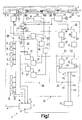
- FIG. 1 schematically shows a dictation device for recording and reproducing voice signals on a recording medium designed as a magnetic tape, which contains a system for recording and evaluating marking signals, with which marking signals of three different types can be recorded and evaluated.
- 2 shows a flow diagram of a program sequence for generating these marking signals of three different types in the device according to FIG. 3 shows the signal formation of a marking signal of a first type generated according to the program flow according to FIG. 2.
- FIG. 4 shows the signal formation of a marking signal of a second type generated according to the program flow according to FIG. 2.
- FIG. 5 shows the signal formation of a Marking signals of a third type generated according to the program flow according to FIG. 2.
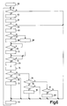
- FIG. 6 shows a flow diagram of a program flow for evaluating marking signals of the three different types according to FIGS. 3, 4 and 5.
- FIG. 7 shows a modification of the exemplary embodiment according to FIG .1 a part of a recording device for marking signals of a second system according to the invention for recording and evaluating marking signals.
- 8 shows, in a modification of the exemplary embodiment according to FIG. 1, part of an evaluation device for marking signals of a third system according to the invention for recording and evaluating marking signals.
- FIG. 9 shows a further marking signal of the third type, which can be generated with a system according to the invention for recording and evaluating marking signals.
- the 10 shows yet another marking signal of the third type that can be generated with a system according to the invention for recording and evaluating marking signals.
- FIG. 1 schematically shows the parts of a table dictation device 1 that are essential to the invention, with which preferably voice signals can be recorded on a magnetic tape 2 accommodated in a cassette (not shown) and can be scanned and reproduced by the magnetic tape.
- a part of the magnetic tape 2 is shown in FIG.
- Provided on the magnetic tape 2 are two tracks 3 and 4, indicated by dash-dotted lines, which can be scanned with the aid of a recording / reproducing magnetic head 5 in the opposite directions of travel of the magnetic tape for recording and reproducing signals.
- the magnetic tape 2 is moved in a direction indicated by an arrow 6.
- This movement of the magnetic tape 2 takes place with the aid of a schematically indicated motorized tape drive device 7, which drives the magnetic tape 2 via winding mandrels, which are coupled with winding cores in a cassette, as is symbolically indicated in FIG. 1 by a dashed line 8.
- the tape drive device 7 has three control inputs 9, 10 and 11, which can be controlled by a control stage 12, in order to switch the tape drive device 7 into three different operating modes, in which the tape with simple normal travel speed in the direction of arrow 6, with 20 times travel speed in Direction of arrow 6 or is driven at twenty times the speed of travel against the direction of arrow 6.
- the tape drive device 7 has a control input 13 via which it can be switched off in order to stop driving the magnetic tape 2.
- control stage 12 is part of a microprocessor 14, which is indicated schematically in FIG. 1 with a dash-dotted line.
- the control stage 12 can be used to determine on the one hand via query inputs 15 whether and which key of a key set 16 has been actuated to switch on operating modes or operating functions of the device.
- the control stage 12 gives control outputs 17 of the same control signals for controlling device parts, such as the belt drive device 7.
- a microphone 18 which can be plugged into the device 1 is connected to the device 1.
- the output signals of the microphone 18 are fed to a recording amplifier circuit 19, the output signals of which are fed to a summing stage 20.
- the output signals of the summing stage 20 are fed to a recording / reproduction changeover switch 21 which, in the switching position shown in full line in FIG. 1, which it assumes for recording signals, feeds the signals fed to it to the magnetic head 5.
- voice signals corresponding to spoken dictations can be recorded on the magnetic tape 2.
- an oscillator 22 is activated, which is a bias or. Deletes the magnetic head 5 when recording signals.
- the recording / playback switch 21 and the oscillator 22 each have a control input 23 and 24, respectively, via which the two can be controlled by the control stage 12.
- the changeover switch 21 is switched from the control stage 12 to its switch position shown in FIG. 1 with a broken line.
- voice signals sampled from the magnetic tape 2 are fed to a reproduction amplifier circuit 25 with the magnetic head 5, the output signals of which are fed to a loudspeaker 26 for acoustic reproduction.
- the output signals of the reproduction amplifier circuit 25 can also be fed to headphones, via which a typist can listen to the stored dictations for writing them down.
- FIG. 1 schematically shows that a first dictation 27 and a second dictation 28 are stored on the magnetic tape 2.
- a dictation device it has proven to be very useful and practical to be able to mark certain locations of the stored dictations or the dictations themselves, if desired, with marking signals.
- marking signals are indicated symbolically in FIG. 1 and designated by the reference symbols M1, M2 and M3.
- there are three different types of marking signals on the device Magnetic tape 2 can be stored and then evaluated again.
- the device 1 has a system 29 for recording and evaluating marking signals M1, M2 and M3 which are recordable and storable on the magnetic tape and can be scanned from the magnetic tape and can be distinguished from one another.
- the device 1 has a button A for triggering the generation and recording of a marking signal M1 of a first type.
- the device 1 has a button B.
- the triggering of the generation and recording of a marking signal M3 of a third type can be triggered, as will be described in more detail below, by pressing the A key twice in succession within a predetermined time period. In this way it is achieved that no separate key is required to trigger the generation and recording of a marking signal of the third type.
- a key C is provided for triggering the evaluation of marking signals M1 of the first type, a key D for triggering the evaluation of marking signals M2 of the second type and a key E for triggering the evaluation of marking signals M3 of the third type.
- the key set 16 also has further keys which are used, for example, to switch on the "recording" operating mode, the "playback” operating mode, the "fast forward” operating mode and the “fast reverse” operating mode and the like.
- the system 29 for recording and evaluating marking signals has a recording device 30, schematically outlined in FIG. 1 with a dashed line, for recording the marking signals to be stored, and an evaluation device 31, likewise outlined in FIG. 1, for evaluating the scanned marking signals.
- the recording device 30 contains a generator device 32 for generating the marking signals to be stored.
- the evaluation device 31 contains a detector device 33 for detecting the scanned marking signals.
- the generator device 32 consists of a first generator stage 34 for generating a first signal which has a first frequency and a second generator stage 35 for generating a second signal which has a second frequency.
- the frequency of the first signal is included 40 Hz and the frequency of the second signal selected at 1500 Hz.
- the two generator stages 34 and 35 are implemented with the aid of the microprocessor 14, the same emitting pulse-shaped signals.
- the pulse-shaped signals of the generator stages 34 and 35 are each fed to a filter stage 36 or 37, which is designed as a low-pass filter and converts the pulse-shaped signals into sinusoidal signals S1 and S2, which are fed to the summing stage 20, via which the signals S1 and S2 are sent to the changeover switch 21 and the magnetic head 5 are supplied.
- the generator device 32 also has a first timing stage Z1 and a second timing stage Z2.
- the occurrence time period for the first signal S1 can be determined with the first time control stage Z1.
- the time period for the second signal S2 can be determined with the second time control stage Z2.
- the two time control stages Z1 and Z2 are also implemented with the aid of the microprocessor 14, the same being designed as time window stages, as can be seen from the following description of the flowchart according to FIG.
- the detector device 33 has two filter stages 38 and 39, to which the signals sampled with the magnetic head 5 are fed via the changeover switch 21.
- the evaluation of the marking signals takes place at a speed of movement of the magnetic tape 2 which is 20 times higher than the recording of the marking signals.
- the filter stage 38 With the filter stage 38, the signal S1 'corresponding to the first signal S1' can be separated from the signal mixture supplied to it at a frequency of 800 Hz.
- the detector device 33 also has a detector stage 40 downstream of the filter stage 38 for detecting the signal S1 ′ corresponding to the first signal and a detector stage 41 downstream of the filter stage 39 for detection of the signal S2 corresponding to the second signal S2 '.
- the two detector stages 40 and 41 are formed, for example, by rectifier stages, which each emit a predetermined output signal D1 or D2 at their output when the corresponding signal S1 'or S2' occurs.
- the detector device 33 has a time measurement stage Z3 following the detector stage 40 and a time measurement stage Z4 following the detector stage 41.
- the occurrence period of the signal S1 ′ or S2 ′ corresponding to the first signal S1 or the second signal S2 can be measured, which in the present device is one twentieth of the occurrence period of the first signal S1 or the second signal S2 is.
- the two time measuring stages Z3 and Z4 are likewise realized with the microprocessor 14 and formed by time counting stages, as can be seen from the following description of the flow chart according to FIG.
- the two time measuring stages Z3 and Z4 are followed by a logic stage 42 which is also implemented with the microprocessor 14 and which the time measuring stages Z3 and Z4 supply different measured values C3 and C4 depending on the measured time span of the signal S1 'and S2' and which depend on them supplied measured values C3 and C4 generated detection signals H1, H2 and H3, which correspond to the marking signals M1, M2 and M3 scanned by the magnetic tape 2.
- the logic stage 42 has three outputs P1, P2 and P3, to which a gate stage 43 is connected, the output of which is connected to the control input 13 of the belt drive device 7 and which, when a detection signal H1, H2 or H3 occurs, at one of the outputs P1, P2 or P3 outputs a control signal to the control input 13 which switches off the tape drive device 7, the driving of the magnetic tape 2 being ended.
- a program sequence in the microprocessor 14 of the device 1 for generating the marking signals M1, M2 and M3 of the three different types with the aid of the system 29 for recording and evaluating marking signals is described below with reference to the flowchart shown in FIG.
- this program flow is started.
- block 45 it is checked whether the key A has been pressed. If so, then at block 46 there will be a time window started for the time period T1 of 500 msec, for example. It is then checked at block 47 whether key A has been pressed a second time. If this is the case, the operator of the device has given the command to generate a marking signal M3 of the third type and to record it on the magnetic tape.
- an operating mode "recording a marking signal” is switched on, in which the tape drive device 7 drives the magnetic tape 2 in the direction of arrow 6 at a simple normal travel speed, the recording / playback switch 21 into that in FIG. 1 with a full one Line switch position shown is switched and the oscillator 22 is turned on to generate a bias signal.
- a time window stage forming the time control stage Z1 is switched on for a time period T of, for example, 650 msec and practically at the same time a time window stage provided as the time control stage Z2 for the time period T / 2, that is to say for 325 msec.
- the generator stage 34 for generating the first signal S1 from the time window stage Z1 for the period T and practically at the same starting time the generator stage 35 for generating the second signal S2 from the time window stage Z2 for the period T / 2 are activated.
- pulse-shaped signals are generated which are converted by filter stages 36 and 37 into sinusoidal signals S1 and S2.
- a marking signal M3 of the third type is generated, as shown in Fig.5.
- the program flow continues at block 51, which is representative of a large number of further program steps. After execution of these program steps according to block 51, the program flow according to FIG. 2 is continued again at block 45.
- the time period T1 of the time window specifies the time period within which the key A must be pressed twice in order to execute the command for generating and recording a marking signal M3 of the third type to give. If the time period T1 has not expired, the program flow continues again at block 47.
- the operating mode becomes analogous to block 48 at block 53 "Recording a marking signal" switched on.
- the time window stage forming time control stage Z1 is switched on for the time period T of 650 msec, and practically at the same time the time window stage forming time control stage Z2 is set to the value zero.
- generator stage 34 is activated by time window stage Z1 for time period T, whereas generator stage 35 is not activated by time window stage Z2 in this case.
- a marking signal M1 of the first type is generated, as shown in FIG. After block 55, the program flow continues at block 51.
- an identification signal is subsequently stored at block 63 for which of these three keys C, D and E has been actuated.
- the operating mode "evaluating a marking signal” is switched on, the magnetic tape 2 first being driven by the tape drive device 7 at twenty times the speed of travel against the direction of the arrow 6 until the start of the magnetic tape 2 is opposite the magnetic head 5, and then the tape drive device 7 drives the magnetic tape 2 in the direction of arrow 6 at twenty times the speed of travel and the recording / playback switch 21 is switched to its switching position shown in FIG. 1 with a broken line. It is then checked at block 65 whether there is an output signal D1 at the output of the detector stage 40.
- a time counting stage provided as a time measuring stage Z3 is started at block 66. It is then checked at block 67 whether there is an output signal D2 at the output of the detector stage 41. If this is not the case, that is, if no signal S2 'is scanned from the magnetic tape, then a time counter stage provided as a time measuring stage Z4 is set to the value zero at block 68, the set counter reading zero then being stored as measured value C4 in the time measuring stage Z4 .
- an output signal D2 is determined at block 67, which means that a signal S2 'is scanned from the magnetic tape 2
- Block 69 started the time counting stage provided as time measuring stage Z4. It is then checked at block 70 whether the output signal D2 of the detector stage 41 is still present. If this is the case, the program flow continues again at block 70, as long as the output signal D2 is present. If it is determined at block 70 that the output signal D2 of the detector stage 41 is no longer present, the time counting stage provided as the time measuring stage Z4 is then stopped at block 71, the counter reading reached then being stored as the measured value C4 in the time measuring stage Z4.
- the program flow continues at block 72, in which it is checked whether the output signal D1 of the detector stage 40 is still present. If this is the case, the program flow continues again at block 72, as long as the output signal D1 is present. If it is determined at block 72 that the output signal D1 of the detector stage 40 is no longer present, then the time counting stage provided as the time measuring stage Z3 is stopped at block 73, the counter reading reached then being stored as the measured value C3 in the time measuring stage Z3.
- the quotient is formed from the counter readings C4 and C3 of the time counter stages Z4 and Z3. It is then checked at block 75 whether this quotient has the value zero. If this is the case, which means that a marking signal M1 of the first type has been sampled, a check is made at block 76 as to whether the key C which has to be pressed to find and evaluate a marking signal M1 of the first type has been pressed. The check at block 76 is carried out by checking the identification signal stored at block 63. If it is determined at block 76 that key C has not been actuated, then the program flow continues at block 62.
- the logic stage 42 outputs a detection signal H1 at its output P1.
- This detection signal H1 indicates that a marking signal M1 of the first type has been evaluated as desired.
- This detection signal H1 is fed via the gate stage 43 to the control input 13 of the belt drive device 7. whereby this is switched off when such a marker signal is found.
- the detection signal H1 could also be used differently, for example in that it is fed to an optical display device for indicating the presence of a marking signal of the first type.
- the logic stage 42 outputs a detection signal H3 at its output P3.
- This detection signal H3 indicates that a marking signal M3 of the third type has been evaluated as desired.
- This detection signal H2 indicates that a marking signal M2 of the second type has been evaluated as desired.
- the program flow continues at block 62. In the event that it is determined at block 81 that the key D has not been pressed either, then it can be assumed that an evaluation process for marking signals was triggered by an operating error, in which case the generation of a detection signal by the logic stage 42 is prevented, and therefore the program flow continues at block 62.
- marking signals of three different types can be recorded in a particularly simple manner on the magnetic tape 2 and can be evaluated by the magnetic tape after they have been scanned.
- the marker signal M1 of the first type consists only of the signal S1, which has a frequency of 40 Hz and occurs in the time T
- the marker signal M2 of the second type and that Marking signal M3 of the third type consists of the first signal S1, which has a frequency of 40 Hz, and the second signal S2, which has a frequency of 1500 Hz
- the time of occurrence of the first signal S1 in these two marking signals M1 and M2 is equal to T.
- the difference between the marker signal M2 of the second type and the marker signal M3 of the third type lies in the fact that the occurrence period of the second signal S2 is only T / 2 for the marker signal M3 of the third type, whereas it is T for the marker signal M2 of the second type. This ensures that the marking signals of the second and third types can also be clearly and correctly distinguished from one another.
- the marking signals of the second type and the third type both consist of the same signals S1 and S2, it is achieved that the marking signals of these two types also with an evaluation device that does not have time measuring stages for the occurrence time periods of the signals S1 and S2 corresponding to the signals S1 and S2 and S2 ', but only detector stages with which the occurrence of these corresponding signals S1' and S2 'can be determined per se, can be detected.
- marking signals of the second type and marking signals of the third type cannot be differentiated from one another according to their type, but the presence of each of these marking signals can very well be determined. Since to evaluate the Marking signals of the quotient, that is, the ratio of the measured values of the time measuring stages is used, the evaluation is advantageously independent of the speed of travel of the magnetic tape when scanning the marking signals.
- Marking signals of the three types mentioned above are recorded by a dictator for the identification of dictations or dictation locations on the magnetic tape.
- Marking signals of the first type each mark, for example, the end of the dictation of a dictation stored on the magnetic tape, for which the dictator has not given any particular information, wishes or requirements regarding the evaluation by a typist.
- Such a marking signal of the first type is then recorded on the magnetic tape if a dictation end of such a dictation stored on the magnetic tape is opposite the recording / reproducing magnetic head.
- Marking signals of the second type each indicate, for example, a dictation location of a dictation stored on the magnetic tape, to which a dictator wants or has given a specific instruction, such as a dictation insertion, a dictation correction or a request relating to the dictation or also a wish that is independent of the dictation , which can also be stored on the magnetic tape or on a separate storage element, such as another magnetic tape or a note.
- Marking signals of the third type identify, for example, the end of the dictation or the beginning of a dictation stored on the magnetic tape, to which the dictator has assigned particular importance or priority over time with regard to the evaluation by a typist; such dictations are called priority dictations.
- a system according to the invention for recording and evaluating marking signals as described above can also be used to store a further marking signal of the third type or also a plurality of such marking signals of the third type on the magnetic tape.
- a further marking signal of the third type can consist of the first signal S1 with a frequency of 40 Hz and with an occurrence time period T and from the second signal S2 with a frequency of 1500 Hz and with an occurrence time period T / 4 be composed.
- Such a further marking signal of the third type can be used, for example, to mark the end of a group of related dictations stored on the magnetic tape, this group of dictations originating, for example, from a single dictator or this group of dictations relating to a related subject area.
- Such a group of related dictations can also be formed in that these dictations are transmitted over a telephone network to a dictation machine that can be connected to the telephone network during a single uninterrupted call, the recording then automatically taking place in this dictation machine after the transmission of these dictations has ended and the call has ended of such a further marking signal of the third type is triggered.
- the generator stages 34 and 35 and the timing stages Z1 and Z2 of the generator device 32 of the recording device 30 are not used, as a modification to the system according to FIG of the microprocessor 14 with Kilfe of discrete components.
- the two generator stages 34 and 35 are designed as sine-wave generators which continuously emit the first signal S1 and the second signal S2.
- the two timing stages Z1 and Z2 are designed as gate circuits which can be controlled by the control stage 12 and which let through the signals S1 and S2 emitted by the generator stages 34 and 35 for a respective time period determined by the control stage 12.
- the signals S1 and S2 passed by the timing stages Z1 and Z2 are fed directly to the summing stage 20, from which the signals S1 and S2 are fed to the recording / reproducing magnetic head for recording on the magnetic tape. In this case, there is no need to provide filter stages for the signals S1 and S2 before they are fed to the summing stage 20.
- the detector device has 33 of the evaluation device 31 has a different structure than the system according to FIG.
- the detector stage 40 with which the signal S1 'corresponding to the signal S1' can be detected, is not followed by a time measuring stage.
- the output signal D1 of the detector stage 40 is fed directly to the logic stage 42 in this detector device 33.
- the detection signals H1, H2 and H3 are not supplied to a gate stage, but rather to an indicator lamp L1, L2 or L3, which are briefly illuminated, for example, to indicate the presence of a marker of the first, second or third type.
- FIG. 4 An example of a further marking signal M4 of the third type is shown in FIG.
- This marking signal M4 is composed of the first signal S1 with a frequency of 40 Hz, for which an occurrence period T is selected, and from the second signal S2 with a frequency of 1500 Hz, for which an occurrence period T / 2 is selected, however, the time of occurrence of the second signal S2 is shifted by a time T / 4 compared to the time of appearance of the first signal S1.
- Such a marker signal is advantageous with regard to its evaluation in that when evaluating the same the time of switching on the time measuring stage for measuring the time of occurrence of the signal S2 corresponding to the second signal is uncritical in relation to switching on the time measuring stage for measuring the Occurrence of the signal S1 ′ corresponding to the first signal S1.
- the first signal S1 again extends over the occurrence time period T and the second signal S2 over an occurrence time period T / 2, which, however, consists of two parts, each with an occurrence time period of T / 4 composed, which are separated by an occurrence gap of T / 2.
- This marker signal has the advantage that despite different lengths of occurrence of the two signals S1 and S2, the two signals S1 and S2 have the same occurrence and the same end time, so that when they are evaluated, the time measuring stages for measuring the occurrence of those corresponding to the signals S1 and S2 Signals S1 'and S2' can be started and stopped at the same time.
- a system for recording and evaluating marking signals for example, its recording device for marking signals can be provided in a separate recording device that is designed only for recording dictations, and its evaluation device in a separate playback device that is designed only for playing back dictations.
- Such a system for recording and reproducing marking signals can be used not only in a dictation system for recording and reproducing dictations, but also in other systems for recording and reproducing other information signals. Marking signals can be recorded when the "recording" mode is activated in a device, or when the "playback” mode is activated in a device, or when the mode "Stop" is activated in a device.
- the marking signals do not have to be recorded together with the information signals in the same track on a recording medium, but can also be recorded in a separate track.
- Other signal compositions are also possible as marking signals of the third type.
- such a further marking signal of the third type from the first signal S1 with an occurrence period T and the second signal S2 with an occurrence period 2T.
- Such a further marking signal of the third type can also be composed of the first signal S1 with an occurrence period T / 3 and the second signal S2 with an occurrence period T.
- the first signal S1 therefore has an occurrence time period which is different from the value T.
Landscapes
- Indexing, Searching, Synchronizing, And The Amount Of Synchronization Travel Of Record Carriers (AREA)
- Recording Or Reproducing By Magnetic Means (AREA)
- Signal Processing For Digital Recording And Reproducing (AREA)
Description
Die Erfindung bezieht sich auf ein System zum Aufzeichnen und Auswerten von auf einem Aufzeichnungsträger speicherbaren und von demselben abtastbaren, voneinander unterscheidbaren Markiersignalen mit einer Aufzeichnungseinrichtung zum Aufzeichnen der zu speichernden Markiersignale und mit einer Auswerteeinrichtung zum Auswerten der abgetasteten Markiersignale, wobei die Aufzeichnungseinrichtung eine Generatoreinrichtung zum Erzeugen der zu speichernden Markiersignale und die Auswerteeinrichtung eine Detektoreinrichtung zum Detektieren der abgetasteten Markiersignale aufweist und die Generatoreinrichtung eine erste Generatorstufe zum Erzeugen eines ersten Signales, das eine erste Frequenz aufweist, eine zweite Generatorstufe zum Erzeugen eines zweiten Signales, das eine zweite Frequenz aufweist wobei die erste und zweite Frequenz unterschiedlich sind, eine erste Zeitsteuerstufe, mit der die Auftrittszeitspanne für das erste Signal festlegbar ist, und eine zweite Zeitsteuerstufe, mit der die Auftrittszeitspanne für das zweite Signal festlegbar ist, enthält, und zum Erzeugen eines nur aus dem ersten Signal bestehenden Markiersignales einer ersten Art die erste Zeitsteuerstufe für die Auftrittszeitspanne des ersten Signales einen vorgegebenen Wert T und zugleich die zweite Zeitsteuerstufe für die Auftrittszeitspanne des zweiten Signales den Wert Null festlegt und zum Erzeugen eines aus dem ersten Signal und dem zweiten Signal bestehenden Markiersignales einer zweiten Art die erste Zeitsteuerstufe für die Auftrittszeitspanne des ersten Signales und zugleich die zweite Zeitsteuerstufe für die Auftrittszeitspanne des zweiten Signales je den Wert T festlegen, und die Detektoreinrichtung eine erste Detektorstufe zum Detektieren eines vom Aufzeichnungsträger abgetasteten, dem ersten Signal entsprechenden Signales und eine zweite Detektorstufe zum Detektieren eines vom Aufzeichnungsträger abgetasteten, dem zweiten Signal entsprechenden Signales, die beide bei Auftreten des betreffenden entsprechenden Signales je ein Ausgangssignal abgeben, und eine den beiden Detektorstufen nachfolgende Logikstufe enthält, die in Abhängigkeit von den Ausgangssignalen der beiden Detektorstufen den vom Aufzeichnungsträger abgetasteten Markiersignalen entsprechende Detektionssignale erzeugt und abgibt.The invention relates to a system for recording and evaluating marking signals that can be stored on a recording medium and can be scanned from the same, distinguishable from one another, with a recording device for recording the marking signals to be stored and with an evaluation device for evaluating the scanned marking signals, the recording device generating a generator device of the marking signals to be stored and the evaluation device has a detector device for detecting the scanned marking signals and the generator device has a first generator stage for generating a first signal having a first frequency, a second generator stage for generating a second signal having a second frequency, the first and the second frequency are different, a first timing stage with which the occurrence period for the first signal can be determined, and a second timing stage with d it contains the occurrence period for the second signal, and, to generate a marking signal of a first type consisting only of the first signal, the first timing stage for the occurrence period of the first signal has a predetermined value T and at the same time the second timing stage for the occurrence period of the second signal defines the value zero and, in order to generate a marking signal of a second type consisting of the first signal and the second signal, the first time control stage for the occurrence period of the first signal and at the same time the second time control stage for the occurrence period of the second signal each determine the value T, and the detector device a first detector stage for detecting a signal scanned by the recording medium and corresponding to the first signal and a second detector stage for detecting a signal scanned by the recording medium and corresponding to the second signal, both of which occur when they occur Each of the corresponding signal in question emit an output signal and contains a logic stage following the two detector stages which, depending on the output signals of the two detector stages, contains the marking signals sampled by the recording medium generates and emits corresponding detection signals.
Ein solches System ist in einem von der Anmelderin hergestellten und vertriebenen Diktiersystem verwendet, das unter der Bezeichnung Mini-Kassetten-Diktiersystem bekannt ist, das Tischdiktiergeräte und tragbare Taschendiktiergeräte, mit denen sowohl das Aufzeichnen als auch das Wiedergeben von Diktaten möglich ist, und Auswertegeräte, die sich nur zum Wiedergeben von Diktaten eignen, umfaßt. Bei diesem bekannten Diktiersystem sind mit dem darin verwendeten eingangs angeführten System zum Aufzeichnen und Auswerten von Markiersignalen Markiersignale zweier unterschiedlicher Arten auf dem als Magnetband ausgebildeten Aufzeichnungsträger speicherbar, um bestimmte Stellen von Diktaten durch Aufzeichnen der Markiersignale kennzeichnen und durch Auswerten der abgetasteten Markiersignale wieder auffinden zu können. Dabei ist mit einem Markiersignal einer ersten Art, das aus einem ersten sinusförmigen Signal mit einer Frequenz von 40 Hz besteht, das beispielsweise während einer Auftrittszeitspanne von 650 msec erzeugt und bei einer vorgegebenen normalen Fortbewegungsgeschwindigkeit des Magnetbandes auf demselben aufgezeichnet wird, jeweils das Ende eines Diktates kennzeichenbar. Mit einem Markiersignal einer zweiten Art, das aus dem ersten sinusförmigen Signal mit der Frequenz von 40 Hz und einem zweiten sinusförmigen Signal mit einer Frequenz von 1500 Hz besteht, die zugleich während derselben Zeitspanne von 650 msec erzeugt und ebenfalls bei der normalen Fortbewegungsgeschwindigkeit des Magnetbandes auf demselben aufgezeichnet werden, sind Diktatstellen kennzeichenbar, zu denen der Diktierende spezielle Instruktionen, Korrekturanweisungen oder dergleichen gegeben hat beziehungsweise geben will, die bei der Diktatauswertung durch eine Schreibkraft von dieser zu berücksichtigen sind. Wie aus vorstehendem hervorgeht, unterscheiden sich bei dem bekannten System die Markiersignale der ersten und zweiten Art dadurch voneinander, daß ein Markiersignal der ersten Art nur aus einem Signal, das eine vorgegebene Frequenz und eine vorgegebene Auftrittszeitspanne aufweist, und ein Markiersignal der zweiten Art aus zwei Signalen besteht, von denen das eine Signal dieselbe Frequenz wie das erste Markiersignal und das andere Signal eine dazu unterschiedliche Frequenz aufweist und die beide dieselbe Auftrittszeitspanne wie das erste Markiersignal aufweisen.Such a system is used in a dictation system manufactured and sold by the applicant, known under the name mini-cassette dictation system, table-top dictation machines and portable pocket dictation machines, with which both the recording and the playback of dictations is possible, and evaluation devices, which are only suitable for playing dictations. In this known dictation system with the system mentioned at the beginning for recording and evaluating marking signals, marking signals of two different types can be stored on the recording medium designed as a magnetic tape, in order to be able to identify specific locations of dictations by recording the marking signals and to be able to find them again by evaluating the scanned marking signals . The end of a dictation is in each case with a marking signal of a first type, which consists of a first sinusoidal signal with a frequency of 40 Hz, which is generated, for example, during an occurrence period of 650 msec and is recorded on the magnetic tape at a predetermined normal speed of travel identifiable. With a marker signal of a second type, which consists of the first sinusoidal signal with a frequency of 40 Hz and a second sinusoidal signal with a frequency of 1500 Hz, which simultaneously generates during the same period of 650 msec and also at the normal speed of travel of the magnetic tape Dictation points to which the dictator has given or wants to give special instructions, correction instructions or the like, which must be taken into account by a typist when evaluating the dictation by a typist, can be identified. As can be seen from the above, in the known system the marking signals of the first and second types differ from one another in that a marking signal of the first type consists only of one signal which has a predetermined frequency and a predetermined occurrence time period, and a marking signal of the second type consists of two Signals exist, of which one signal has the same frequency as the first marker signal and the other signal one has a different frequency and both have the same time span as the first marker signal.
Die Auswertung der vom Magnetband abgetasteten Markiersignale der ersten und zweiten Art erfolgt bei dem bekannten System bei einer gegenüber dem Aufzeichnen der Markiersignale höheren Fortbewegungsgeschwindigkeit des Magnetbandes, wobei diese Fortbewegungsgeschwindigkeit beispielsweise um einen Faktor 20 höher ist als die Fortbewegungsgeschwindigkeit beim Aufzeichnen der Markiersignale. Durch diese höhere Fortbewegungsgeschwindigkeit bei der Auswertung der abgetasteten Markiersignale kommt es zu einer Transponierung der Frequenzen der Signale, aus denen die Markiersignale bestehen, um einen Faktor 20, so daß bei der Auswertung eines Markiersignales der ersten Art ein dem ersten sinusförmigen Signal mit einer Frequenz von 40 Hz entsprechendes Signal mit einer Frequenz von 800 Hz und bei der Auswertung eines Markiersignales der zweiten Art ein dem ersten sinusförmigen Signal mit einer Frequenz von 40 Hz entsprechendes Signal mit einer Frequenz von 800 Hz und ein dem zweiten sinusförmigen Signal mit einer Frequenz von 1500 Hz entsprechendes Signal mit einer Frequenz von 30 kHz von dem Magnetband abgetastet wird. Aufgrund dieses Sachverhaltes weist die Auswerteeinrichtung für die vom Magnetband abgetasteten Markiersignale der ersten und zweiten Art bei dem bekannten System eine Detektoreinrichtung auf, die eine erste Detektorstufe zum Detektieren eines Signales mit einer Frequenz von 800 Hz und eine zweite Detektorstufe zum Detektieren eines Signales mit einer Frequenz von 30 kHz enthält, die beide bei Auftreten des entsprechenden Signales je ein Ausgangssignal abgeben, die einer den beiden Detektorstufen nachfolgenden Logikstufe zugeführt werden. Wenn nur die erste Detektorstufe ein solches Ausgangssignal abgibt, erzeugt die Logikstufe ein einem Markiersignal der ersten Art entsprechendes Detektionssignal. Wenn beide Detektorstufen ein solches Ausgangssignal abgeben, erzeugt die Logikstufe ein einem Markiersignal der zweiten Art entsprechendes Detektionssignal. Diese Detektionssignale können einer optischen oder akustischen Anzeigeeinrichtung zugeführt werden. Sie können aber auch einer Abschalteinrichtung zum Abschalten der Antriebseinrichtung für das Magnetband zugeführt werden, wobei dann durch Abschalten der Antriebseinrichtung für das Magnetband die Fortbewegung des Magnetbandes unterbrochen wird, wenn ein Markiersignal detektiert wird.The evaluation of the marking signals of the first and second types scanned by the magnetic tape takes place in the known system at a higher moving speed of the magnetic tape than the recording of the marking signals, this moving speed being for example a
Bei dem bekannten System zum Aufzeichnen und Auswerten von Markiersignalen ist es, wie vorstehend beschrieben, nur möglich, voneinander unterscheidbare Markiersignale einer ersten und einer zweiten Art aufzuzeichnen und auszuwerten. Im Zuge der Verwendung der Geräte des bekannten Diktiersystems hat sich dies als nachteilige Einschränkung herausgestellt, da sich ein Bedarf an weiteren Markierungsmöglichkeiten mit Markiersignalen ergeben hat, die aber bei dem bekannten System zum Aufzeichnen und Auswerten von Markiersignalen nicht möglich sind.In the known system for recording and evaluating marking signals, as described above, it is only possible to record and evaluate distinguishable marking signals of a first and a second type. In the course of using the devices of the known dictation system, this has proven to be a disadvantageous restriction, since there has been a need for further marking options with marking signals, which are not possible with the known system for recording and evaluating marking signals.
Die Erfindung hat sich daher zur Aufgabe gestellt, diesen Bedarf zufriedenzustellen und ein System der eingangs angeführten Gattung erfindungsgemäß so auszubilden, daß mit dem erfindungsgemäßen System zumindest ein Markiersignal einer dritten Art erzeugbar und auswertbar ist, wobei zwar nicht die Art eines solchen Markiersignales der dritten Art, wohl aber das Vorhandensein desselben auch mit einer Auswerteeinrichtung des bekannten bestehenden System festgestellt werden kann, um hinsichtlich der Feststellung des Vorhandenseins von Markiersignalen Kompatibilität zwischen dem bestehenden System und dem erfindungsgemäßen System zu gewährleisten. Zur Realisierung dieser gestellten Aufgabe ist gemäß der Erfindung vorgesehen, daß zum Erzeugen mindestens eines aus dem ersten Signal und dem zweiten Signal bestehenden Markiersignales einer dritten Art mindestens eine der beiden Zeitsteuerstufen die mit ihr festlegbare Auftrittszeitspanne für das betreffende Signal auf mindestens einen vom Wert T unterschiedlichen Wert festlegt und daß die Detektoreinrichtung zusätzlich zu den beiden Detektorstufen zum Detektieren der beiden vom Aufzeichnungsträger abgetasteten, dem ersten Signal und dem zweiten Signal entsprechenden Signale für mindestens eines dieser beiden entsprechenden Signale, das einem der beiden Signale entspricht, für das mit einer der beiden Zeitsteuerstufen mindestens eine vom Wert T unterschiedliche Auftrittszeitspanne festlegbar ist, eine Zeitmeßstufe zum Messen der Auftrittszeit spanne dieses mindestens einen entsprechenden Signales enthält, die je nach gemessener Auftrittszeitspanne unterschiedliche Meßwerte der Logikstufe zum Erzeugen der den vom Aufzeichnungsträger abgetasteten Markiersignalen entsprechenden Detektionssignale zuführt. Auf diese Weise ist erreicht, daß mindestens ein neues Markiersignal einer dritten Art zur Verfügung steht, das aus zwei Signalen mit unterschiedlichen Frequenzen besteht, aus denen auch ein bekanntes Markiersignal der zweiten Art besteht. Zur Unterscheidung eines neuen Markiersignales der dritten Art von einem bekannten Markiersignal der zweiten Art ist die Auftrittszeitspanne zumindest eines Signales in einem Markiersignal der dritten Art gegenüber der Auftrittszeitspanne dieses Signales in einem Markiersignal der zweiten Art unterschiedlich festgelegt, so daß durch Detektion dieser unterschiedlichen Auftrittszeitspanne ein Markiersignal der dritten Art eindeutig von einem Markiersignal der zweiten Art unterscheidbar ist. Da ein solches neues Markiersignal der dritten Art aus denselben beiden Signalen besteht wie ein bekanntes Markiersignal der zweiten Art, kann ein Markiersignal der dritten Art auch mit einer zum Auswerten eines Markiersignales der zweiten Art vorgesehenen Auswerteeinrichtung des bestehenden bekannten Systems festgestellt werden, wobei zwar nicht die Art eines neuen Markiersignales der dritten Art von der Art eines bekannten Markiersignales der zweiten Art unterschieden werden kann, aber sehr wohl das Vorhandensein eines solchen Markiersignales der dritten Art an sich festgestellt werden kann. Auf diese Weise ist somit hinsichtlich der Feststellung des Vorhandenseins von Markiersignalen Kompatibilität zwischen dem bestehenden bekannten System und dem erfindungsgemäßen System erreicht.The invention has therefore set itself the task of satisfying this need and designing a system of the type mentioned at the beginning in such a way that at least one marking signal of a third type can be generated and evaluated with the system according to the invention, although not the type of such a marking signal of the third type , but the presence of the same can also be determined with an evaluation device of the known existing system in order to ensure compatibility between the existing system and the system according to the invention with regard to the determination of the presence of marking signals. To achieve this object, according to the invention it is provided that for generating at least one marking signal of a third type consisting of the first signal and the second signal, at least one of the two timing stages, the time period that can be defined with it for the signal in question to at least one that differs from the value T. Specifies value and that the detector device in addition to the two detector stages for detecting the two signals sampled by the recording medium, corresponding to the first signal and the second signal, for at least one of these two corresponding signals, which corresponds to one of the two signals, for that with one of the two timing stages at least one occurrence period different from the value T can be specified, a time measuring stage for measuring the occurrence time span contains at least one corresponding signal which, depending on the measured time span, supplies different measured values of the logic stage for generating the detection signals corresponding to the marking signals scanned by the recording medium. In this way it is achieved that at least one new marking signal of a third type is available, which consists of two signals with different frequencies, from which a known marking signal of the second type also consists. In order to distinguish a new marking signal of the third type from a known marking signal of the second type, the occurrence time period of at least one signal in a marking signal of the third type is defined differently from the occurrence time period of this signal in a marking signal of the second type, so that a detection signal of this different occurrence time period defines a marking signal of the third type is clearly distinguishable from a marker signal of the second type. Since such a new marking signal of the third type consists of the same two signals as a known marking signal of the second type, a marking signal of the third type can also be determined with an evaluation device provided in the existing known system for evaluating a marking signal of the second type, although not the one Type of a new marker signal of the third type can be distinguished from the type of a known marker signal of the second type, but the presence of such a marker signal of the third type can be determined per se. In this way, compatibility between the existing known system and the system according to the invention is thus achieved with regard to the determination of the presence of marking signals.
An dieser Stelle sei erwähnt, daß es beispielsweise aus der DE-OS 20 29 090 an sich bekannt ist, Markiersignale mit unterschiedlich langer Auftrittszeitspanne zu verwenden. Gemäß der DE-OS 20 29 090 bestehen alle diese bekannten Markiersignale aber nur aus einem einzigen Signal, das eine vorgegebene Frequenz aufweist, wogegen erfindungsgemäß die Markiersignale aus zwei Signalen mit unterschiedlichen Frequenzen und unterschiedlichen Auftrittszeitspannen bestehen, was den Vorteil mit sich bringt, daß die Auswertung dieser Markiersignale auf einfache Weise unabhängig von der Antriebs- bzw. Fortbewegungsgeschwindigkeit des Aufzeichnungsträgers beim Auswerten erfolgen kann.At this point it should be mentioned that it is known per se, for example from DE-OS 20 29 090, to use marking signals with different lengths of occurrence. According to DE-OS 20 29 090, however, all these known marking signals only consist of a single signal which has a predetermined frequency, whereas according to the invention the marking signals consist of two signals with different frequencies and different periods of occurrence, which has the advantage that the evaluation of these marking signals can be carried out in a simple manner regardless of the drive or travel speed of the recording medium during the evaluation.
Zum Erzeugen mindestens eines Markiersignales der dritten Art können sowohl die erste Zeitsteuerstufe als auch die zweite Zeitsteuerstufe für die Auftrittszeitspannen des betreffenden Signales je mindestens einen von den Werten Null und T unterschiedlichen Wert festlegen. Als vorteilhaft hat sich aber erwiesen, wenn zum Erzeugen mindestens eines Markiersignales der dritten Art die erste Zeitsteuerstufe für die Auftrittszeitspanne des ersten Signales den Wert T und zugleich die zweite Zeitsteuerstufe für die Auftrittszeitspanne des zweiten Signales mindestens einen vom Wert T unterschiedlichen Wert festlegt. Dies ist im Hinblick auf eine einfache Erzeugung und Detektion aller Markiersignale vorteilhaft, weil die Auftrittszeitspanne des ersten Signales, das die erste Frequenz aufweist, in allen Markiersignalen der drei unterschiedlichen Arten gleich lang ist. Hiedurch braucht bei der Auswertung aller Markiersignale der drei unterschiedlichen Arten nur das Vorhandensein des dem ersten Signal entsprechenden Signales an sich mit der ersten Detektorstufe detektiert werden, ohne daß die Auftrittszeitspanne des dem ersten Signal entsprechenden Signales ermittelt werden muß.To generate at least one marker signal of the third type, both the first timing stage and the second timing stage for the occurrence periods of the signal in question can each define at least one value different from the values zero and T. It has proven to be advantageous, however, if, in order to generate at least one marking signal of the third type, the first timing stage for the occurrence period of the first signal defines the value T and at the same time the second timing stage for the occurrence period of the second signal defines at least one value different from the value T. This is advantageous with regard to a simple generation and detection of all marking signals, because the time of occurrence of the first signal, which has the first frequency, is of the same length in all marking signals of the three different types. In this way, when evaluating all the marking signals of the three different types, only the presence of the signal corresponding to the first signal needs to be detected with the first detector stage, without the occurrence period of the signal corresponding to the first signal having to be determined.
Als vorteilhaft hat sich dabei weiters erwiesen, wenn zum Erzeugen eines Markiersignales der dritten Art die erste Zeitsteuerstufe für die Auftrittszeitspanne des ersten Signales den Wert T und zugleich die zweite Zeitsteuerstufe für die Auftrittszeitspanne des zweiten Signales den Wert T/2 festlegt. Ein solches Markiersignal der dritten Art ist besonders sicher und leicht von den bekannten Markiersignalen der ersten und zweiten Art unterscheidbar, was im Hinblick auf eine einwandfreie Detektion der Markiersignale vorteilhaft ist.It has also proven to be advantageous if, in order to generate a marking signal of the third type, the first timing stage defines the value T for the occurrence period of the first signal and at the same time the second timing stage specifies the value T / 2 for the occurrence period of the second signal. Such a marking signal of the third type is particularly reliable and easily distinguishable from the known marking signals of the first and second types, which is advantageous with regard to a flawless detection of the marking signals.
Weiters hat sich als vorteilhaft erwiesen, wenn zum Erzeugen mindestens eines Markiersignales der dritten Art die beiden Zeitsteuerstufen für die Auftrittszeitspannen der beiden Signale denselben Startzeitpunkt festlegen. Dies ist im Hinblick auf eine möglichst einfache zeitliche Steuerung der Zeitsteuerstufen vorteilhaft.Furthermore, it has proven to be advantageous if, in order to generate at least one marking signal of the third type, the two timing stages for the occurrence periods of the two signals define the same starting time. This is in view advantageous for the simplest possible timing of the timing stages.
Die Zeitsteuerstufen können beispielsweise als Torschaltungen ausgebildet sein, die von den Generatorstufen dauernd erzeugte erste und zweite Signale für die jeweilige Auftrittszeitspanne durchlassen. Als vorteilhaft hat sich aber erwiesen, wenn die beiden Zeitsteuerstufen die beiden Generatorstufen zum Erzeugen des ersten Signales und des zweiten Signales aktivieren. Dies ist im Falle einer Ausbildung der Generatorstufen mit diskreten Bauteilen im Hinblick auf einen möglichst geringen Energieverbrauch und im Falle einer Ausbildung der Generatorstufen mit einem Mikroprozessor im Hinblick auf einen möglichst einfachen Programmablauf und folglich einen möglichst geringen Speicherplatzbedarf vorteilhaft.The time control stages can be designed, for example, as gate circuits which pass through first and second signals continuously generated by the generator stages for the respective time period. However, it has proven to be advantageous if the two timing stages activate the two generator stages for generating the first signal and the second signal. This is advantageous if the generator stages are designed with discrete components with regard to the lowest possible energy consumption and if the generator stages are designed with a microprocessor with regard to the simplest possible program execution and consequently the smallest possible storage space requirement.
Weiters hat sich bei einem erfindungsgemäßen System mit einem zum Auslösen des Erzeugens und Aufzeichnens eines Markiersignales der ersten Art vorgesehenen ersten Bedienungsorgan und mit einem zum Auslösen des Erzeugens und Aufzeichnens eines Markiersignales der zweiten Art vorgesehenen zweiten Bedienungsorgan, die von dem eingangs erwähnten bestehenden Mini-Kassetten-Diktiersystem her an sich bekannt sind, als vorteilhaft erwiesen, wenn das Erzeugen und Aufzeichnen mindestens eines Markiersignales der dritten Art durch innerhalb einer vorgegebenen Zeitdauer mindestens zweifach aufeinanderfolgendes Betätigen eines der beiden Bedienungsorgane auslösbar ist. Auf diese Weise erübrigt sich das Vorsehen von mindestens einem separaten Bedienungsorgan zum Auslösen des Erzeugens und Aufzeichnens von mindestens einem Markiersignal der dritten Art, was im Hinblick auf eine möglichst einfache Geräteausbildung mit möglichst wenigen Bedienungsorganen vorteilhaft ist.Furthermore, in a system according to the invention, with a first operating element provided for triggering the generation and recording of a marking signal of the first type and with a second operating element provided for triggering the generation and recording of a marking signal of the second type, the existing mini-cassettes mentioned above -Dictation system are known per se, proven to be advantageous if the generation and recording of at least one marking signal of the third type can be triggered by actuating one of the two operating elements at least twice in succession within a predetermined time period. In this way, there is no need to provide at least one separate control element for triggering the generation and recording of at least one marking signal of the third type, which is advantageous with regard to the simplest possible device design with as few control elements as possible.
Weiters hat sich bei einem erfindungsgemäßen System als vorteilhaft erwiesen, wenn die Detektoreinrichtung für das vom Aufzeichnungsträger abgetastete, dem ersten Signal entsprechende Signal eine erste Zeitmeßstufe zum Messen der Auftrittszeitspanne dieses entsprechenden Signales und für das vom Aufzeichnungsträger abgetastete, dem zweiten Signal entsprechende Signal eine zweite Zeitmeßstufe zum Messen der Auftrittszeitspanne dieses entsprechenden Signales enthält, die beide die von ihnen ermittelten Meßwerte der Logikstufe zuführen, und die Logikstufe in Abhängigkeit vom Verhältnis der ihr zugeführten Meßwerte die den abgetasteten Markiersignalen entsprechenden Detektionssignale erzeugt. Hiedurch ist erreicht, daß die Auswertung der abgetasteten Markiersignale unabhängig von der Antriebs- bzw. Fortbewegungsgeschwindigkeit des Aufzeichnungsträgers beim Abtasten der Markiersignale ist.Furthermore, it has proven to be advantageous in a system according to the invention if the detector device has a first time measuring stage for the signal corresponding to the first signal sampled by the recording medium for measuring the occurrence period of this corresponding signal and a second time measuring stage for the signal corresponding to the second signal sampled by the recording medium to measure the Occurrence period of this corresponding signal, both of which feed the measured values determined by them to the logic stage, and the logic stage generates the detection signals corresponding to the scanned marking signals as a function of the ratio of the measured values fed to it. It is thereby achieved that the evaluation of the scanned marking signals is independent of the driving or moving speed of the recording medium when scanning the marking signals.
Die Erfindung wird im folgenden anhand von in den Zeichnungen dargestellten Ausführungsbeispielen, auf die dieselbe jedoch nicht beschränkt sein soll, näher beschrieben. Die Fig.1 zeigt schematisch ein Diktiergerät zum Aufzeichnen und Wiedergeben von Sprachsignalen auf einem als Magnetband ausgebildeten Aufzeichnungsträger, das ein System zum Aufzeichnen und Auswerten von Markiersignalen enthält, mit dem Markiersignale dreier unterschiedlicher Arten aufzeichenbar und auswertbar sind. Die Fig.2 zeigt ein Flußdiagramm eines Programmablaufes zum Erzeugen dieser Markiersignale dreier unterschiedlicher Arten bei dem Gerät gemäß Fig.1. Die Fig.3 zeigt die Signalausbildung eines gemäß dem Programmablauf nach Fig.2 erzeugten Markiersignales einer ersten Art. Die Fig.4 zeigt die Signalausbildung eines gemäß dem Programmablauf nach Fig.2 erzeugten Markiersignales einer zweiten Art. Die Fig.5 zeigt die Signalausbildung eines gemäß dem Programmablauf nach Fig.2 erzeugten Markiersignales einer dritten Art. Die Fig.6 zeigt ein Flußdiagramm eines Programmablaufes zum Auswerten von Markiersignalen der drei unterschiedlichen Arten gemäß den Figuren 3, 4 und 5. Die Fig.7 zeigt in Abwandlung des Ausführungsbeispieles gemäß Fig.1 einen Teil einer Aufzeichnungseinrichtung für Markiersignale eines zweiten erfindungsgemäßen Systems zum Aufzeichnen und Auswerten von Markiersignalen. Die Fig.8 zeigt in Abwandlung des Ausführungsbeispieles gemäß Fig.1 einen Teil einer Auswerteeinrichtung für Markiersignale eines dritten erfindungsgemäßen Systems zum Aufzeichnen und Auswerten von Markiersignalen. Die Fig.9 zeigt ein weiteres Markiersignal der dritten Art, das mit einem erfindungsgemäßen System zum Aufzeichnen und Auswerten von Markiersignalen erzeugbar ist. Die Fig.10 zeigt noch ein weiteres Markiersignal der dritten Art, das mit einem erfindungsgemäßen System zum Aufzeichnen und Auswerten von Markiersignalen erzeugbar ist.The invention is described in more detail below with reference to exemplary embodiments shown in the drawings, to which the same is, however, not intended to be limited. 1 schematically shows a dictation device for recording and reproducing voice signals on a recording medium designed as a magnetic tape, which contains a system for recording and evaluating marking signals, with which marking signals of three different types can be recorded and evaluated. 2 shows a flow diagram of a program sequence for generating these marking signals of three different types in the device according to FIG. 3 shows the signal formation of a marking signal of a first type generated according to the program flow according to FIG. 2. FIG. 4 shows the signal formation of a marking signal of a second type generated according to the program flow according to FIG. 2. FIG. 5 shows the signal formation of a Marking signals of a third type generated according to the program flow according to FIG. 2. FIG. 6 shows a flow diagram of a program flow for evaluating marking signals of the three different types according to FIGS. 3, 4 and 5. FIG. 7 shows a modification of the exemplary embodiment according to FIG .1 a part of a recording device for marking signals of a second system according to the invention for recording and evaluating marking signals. 8 shows, in a modification of the exemplary embodiment according to FIG. 1, part of an evaluation device for marking signals of a third system according to the invention for recording and evaluating marking signals. FIG. 9 shows a further marking signal of the third type, which can be generated with a system according to the invention for recording and evaluating marking signals. The 10 shows yet another marking signal of the third type that can be generated with a system according to the invention for recording and evaluating marking signals.
Die Fig.1 zeigt schematisch die erfindungswesentlichen Teile eines Tischdiktiergerätes 1, mit dem vorzugsweise Sprachsignale auf einem in einer nicht dargestellten Kassette untergebrachten Magnetband 2 aufgezeichnet und von dem Magnetband wieder abgetastet und wiedergegeben werden können. In Fig.1 ist ein Teil des Magnetbandes 2 dargestellt. Auf dem Magnetband 2 sind zwei mit strichpunktierten Linien angedeutete Spuren 3 und 4 vorgesehen, die bei entgegengesetzten Fortbewegungsrichtungen des Magnetbandes zum Aufzeichnen und Wiedergeben von Signalen mit Hilfe eines Aufzeichnungs/Wiedergabe-Magnetkopfes 5 abtastbar sind.1 schematically shows the parts of a
Zum Abtasten der Spur 3 wird das Magnetband 2 in einer mit einem Pfeil 6 angegebenen Richtung fortbewegt. Dieses Fortbewegen des Magnetbandes 2 erfolgt mit Hilfe einer schematisch angedeuteten motorischen Bandantriebseinrichtung 7, die über Wickeldorne, die mit Wickelkernen in einer Kassette gekoppelt sind, das Magnetband 2 antreibt, wie dies in Fig.1 symbolisch mit einer strichlierten Linie 8 angedeutet ist. Die Bandantriebseinrichtung 7 weist drei Steuereingänge 9, 10 und 11 auf, die von einer Steuerstufe 12 ansteuerbar sind, um die Bandantriebseinrichtung 7 in drei unterschiedliche Betriebsweisen zu schalten, in denen das Band mit einfacher normaler Fortbewegungsgeschwindigkeit in Richtung des Pfeiles 6, mit zwanzigfacher Fortbewegungsgeschwindigkeit in Richtung des Pfeiles 6 bzw. mit zwanzigfacher Fortbewegungsgeschwindigkeit entgegen der Richtung des Pfeiles 6 angetrieben wird. Weiters weist die Bandantriebseinrichtung 7 einen Steuereingang 13 auf, über den dieselbe abgeschaltet werden kann, um das Antreiben des Magnetbandes 2 zu beenden.To scan the track 3, the
Die Steuerstufe 12 ist bei vorliegendem Gerät Teil eines Mikroprozessors 14, der in Fig.1 mit einer strichpunktierten Linie schematisch angedeutet ist. Mit der Steuerstufe 12 ist einerseits über Abfrageeingänge 15 derselben feststellbar, ob und welche Taste eines Tastensatzes 16 zum Einschalten von Betriebsarten bzw. Betriebsfunktionen des Gerätes betätigt wurde. Andererseits gibt die Steuerstufe 12 über Steuerausgänge 17 derselben Steuersignale zur Steuerung von Geräteteilen, wie etwa der Bandantriebseinrichtung 7, ab.In the present device, the
Mit dem Gerät 1 ist ein an dasselbe ansteckbares Mikrofon 18 verbunden. Die Ausgangssignale des Mikrofons 18 werden einer Aufzeichnungsverstärkerschaltung 19 zugeführt, deren Ausgangssignale einer Summierstufe 20 zugeleitet werden. Die Ausgangssignale der Summierstufe 20 werden einem Aufzeichnungs/Wiedergabe-Umschalter 21 zugeführt, der in der in Fig.1 mit einer vollen Linie dargestellten Schaltstellung, die er zum Aufzeichnen von Signalen einnimmt, die ihm zugeführten Signale dem Magnetkopf 5 zuleitet. Auf diese Weise sind Sprachsignale, die gesprochenen Diktaten entsprechen, auf dem Magnetband 2 aufzeichenbar. Beim Aufzeichnen von Signalen wird ein Oszillator 22 aktiviert, der ein Vormagnetisierungs-bzw. Löschsignal beim Aufzeichnen von Signalen dem Magnetkopf 5 zuführt. Der Aufzeichnungs/Wiedergabe-Umschalter 21 und der Oszillator 22 weisen je einen Steuereingang 23 bzw. 24 auf, über die die beiden von der Steuerstufe 12 steuerbar sind.A
Zum Wiedergeben von Sprachsignalen wird der Umschalter 21 von der Steuerstufe 12 in seine in Fig.1 mit einer strichlierten Linie dargestellte Schaltstellung umgeschaltet. Dadurch werden mit dem Magnetkopf 5 vom Magnetband 2 abgetastete Sprachsignale einer Wiedergabeverstärkerschaltung 25 zugeführt, deren Ausgangssignale zur akustischen Wiedergabe einem Lautsprecher 26 zugeleitet werden. Anstelle des Lautsprechers können die Ausgangssignale der Wiedergabeverstärkerschaltung 25 auch einem Kopfhörer zugeleitet werden, über den eine Schreibkraft die gespeicherten Diktate zum Niederschreiben abhören kann.To reproduce voice signals, the
In Fig.1 ist schematisch dargestellt, daß auf dem Magnetband 2 ein erstes Diktat 27 und ein zweites Diktat 28 gespeichert sind. Bei einem solchen Diktiergerät hat es sich als sehr nützlich und praktisch erwiesen, bestimmte Stellen der gespeicherten Diktate bzw. die Diktate selbst erwünschtenfalls mit Markiersignalen markieren zu können. In Fig.1 sind solche Markiersignale symbolisch angedeutet und mit den Bezugszeichen M1, M2 und M3 bezeichnet. Wie aus der nachfolgenden Beschreibung noch genau hervorgeht, sind bei vorliegendem Gerät Markiersignale dreier unterschiedlicher Arten auf dem Magnetband 2 speicherbar und danach wieder auswertbar.1 schematically shows that a
Das Gerät 1 weist hiefür ein System 29 zum Aufzeichnen und Auswerten von auf dem Magnetband aufzeichenbaren und speicherbaren und von dem Magnetband abtastbaren, voneinander unterscheidbaren Markiersignalen M1, M2 und M3 auf. Zum Auslösen des Erzeugens und Aufzeichnens eines Markiersignales M1 einer ersten Art weist das Gerät 1 eine Taste A auf. Zum Auslösen des Erzeugens und Aufzeichnens eines Markiersignales M2 einer zweiten Art weist das Gerät 1 eine Taste B auf. Das Auslösen des Erzeugens und Aufzeichnens eines Markiersignales M3 einer dritten Art ist, wie nachfolgend noch näher beschrieben ist, durch innerhalb einer vorgegebenen Zeitdauer zweifach aufeinanderfolgendes Betätigen der Taste A auslösbar. Auf diese Weise ist erreicht, daß zum Auslösen des Erzeugens und Aufzeichnens eines Markiersignales der dritten Art keine separate Taste erforderlich ist. Zum Auslösen des Auswertens von Markiersignalen M1 der ersten Art ist eine Taste C, zum Auslösen des Auswertens von Markiersignalen M2 der zweiten Art eine Taste D und zum Auslösen des Auswertens von Markiersignalen M3 der dritten Art eine Taste E vorgesehen. Der Tastensatz 16 weist noch weitere Tasten auf, die beispielsweise zum Einschalten der Betriebsart "Aufzeichnen", der Betriebsart "Wiedergeben", der Betriebsart "Schneller Vorlauf" und der Betriebsart "Schneller Rücklauf" und dergleichen dienen.For this purpose, the
Das System 29 zum Aufzeichnen und Auswerten von Markiersignalen weist eine in Fig.1 schematisch mit einer strichlierten Linie umrandete Aufzeichnungseinrichtung 30 zum Aufzeichnen der zu speichernden Markiersignale und eine in Fig.1 ebenfalls mit einer strichlierten Linie umrandete Auswerteeinrichtung 31 zum Auswerten der abgetasteten Markiersignale auf. Die Aufzeichnungseinrichtung 30 enthält dabei eine Generatoreinrichtung 32 zum Erzeugen der zu speichernden Markiersignale. Die Auswerteeinrichtung 31 enthält eine Detektoreinrichtung 33 zum Detektieren der abgetasteten Markiersignale.The
Die Generatoreinrichtung 32 besteht aus einer ersten Generatorstufe 34 zum Erzeugen eines ersten Signales, das eine erste Frequenz aufweist, und einer zweiten Generatorstufe 35 zum Erzeugen eines zweiten Signales, das eine zweite Frequenz aufweist. Dabei ist die Frequenz des ersten Signales mit 40 Hz und die Frequenz des zweiten Signales mit 1500 Hz gewählt. In vorliegendem Fall sind die beiden Generatorstufen 34 und 35 mit Hilfe des Mikroprozessors 14 realisiert, wobei dieselben impulsförmige Signale abgeben. Die impulsförmigen Signale der Generatorstufen 34 und 35 werden je einer als Tiefpaßfilter ausgebildeten Filterstufe 36 bzw. 37 zugeführt, die die impulsförmigen Signale in sinusförmige Signale S1 und S2 umformen, die der Summierstufe 20 zugeführt werden, über die die Signale S1 und S2 dem Umschalter 21 und dem Magnetkopf 5 zugeleitet werden. Die Generatoreinrichtung 32 weist ferner eine erste Zeitsteuerstufe Z1 und eine zweite Zeitsteuerstufe Z2 auf. Mit der ersten Zeitsteuerstufe Z1 ist die Auftrittszeitspanne für das erste Signal S1 festlegbar. Mit der zweiten Zeitsteuerstufe Z2 ist die Auftrittszeitspanne für das zweite Signal S2 festlegbar. Auch die beiden Zeitsteuerstufen Z1 und Z2 sind mit Hilfe des Mikroprozessors 14 realisiert, wobei dieselben als Zeitfensterstufen ausgebildet sind, wie aus nachfolgender Beschreibung des Flußdiagrammes gemäß Fig.2 hervorgeht.The
Die Detektoreinrichtung 33 weist zwei Filterstufen 38 und 39 auf, denen die mit dem Magnetkopf 5 abgetasteten Signale über den Umschalter 21 zugeführt werden. An dieser Stelle ist festzuhalten, daß das Auswerten der Markiersignale bei einer gegenüber dem Aufzeichnen der Markiersignale um den Faktor 20 höheren Fortbewegungsgeschwindigkeit des Magnetbandes 2 erfolgt. Hiedurch erfolgt beim Abtasten der Markiersignale eine Frequenztransponierung der gespeicherten Signale S1 und S2, so daß den Signalen S1 und S2 entsprechende Signale S1′ und S2′ abgetastet werden, die eine Frequenz von 800 Hz und eine Frequenz von 30 kHz aufweisen. Mit der Filterstufe 38 ist aus dem ihr zugeführten Signalgemisch das dem ersten Signal S1 entsprechende Signal S1′ mit einer Frequenz von 800 Hz abtrennbar. Mit der zweiten Filterstufe 39 ist aus dem ihr zugeführten Signalgemisch das dem zweiten Signal S2 entsprechende Signal S2′ mit einer Frequenz von 30 kHz abtrennbar. Die Detektoreinrichtung 33 weist weiters eine der Filterstufe 38 nachgeschaltete Detektorstufe 40 zum Detektieren des dem ersten Signal entsprechenden Signales S1′ und eine der Filterstufe 39 nachgeschaltete Detektorstufe 41 zum Detektieren des dem zweiten Signal S2 entsprechenden Signales S2′ auf. Die beiden Detektorstufen 40 und 41 sind beispielsweise durch Gleichrichterstufen gebildet, die bei Auftreten des betreffenden entsprechenden Signales S1′ bzw. S2′ an ihrem Ausgang je ein vorgegebenes Ausgangssignal D1 bzw. D2 abgeben. Weiters weist die Detektoreinrichtung 33 eine der Detektorstufe 40 nachfolgende Zeitmeßstufe Z3 und eine der Detektorstufe 41 nachfolgende Zeitmeßstufe Z4 auf. Mit den beiden Zeitmeßstufen Z3 und Z4 ist jeweils die Auftrittszeitspanne des dem ersten Signal S1 bzw. dem zweiten Signal S2 entsprechenden Signales S1′ bzw. S2′ meßbar, die bei vorliegendem Gerät ein Zwanzigstel der Auftrittszeitspanne des ersten Signales S1 bzw. des zweiten Signales S2 ist. Die beiden Zeitmeßstufen Z3 und Z4 sind ebenfalls mit dem Mikroprozessor 14 realisiert und durch Zeitzählstufen gebildet, wie aus nachfolgender Beschreibung des Flußdiagrammes gemäß Fig.6 hervorgeht. Den beiden Zeitmeßstufen Z3 und Z4 folgt eine ebenfalls mit dem Mikroprozessor 14 realisierte Logikstufe 42 nach, der die Zeitmeßstufen Z3 und Z4 je nach gemessener Auftrittszeitspanne des Signales S1′ bzw. S2′ unterschiedliche Meßwerte C3 bzw. C4 zuführen und die in Abhängigkeit von den ihr zugeführten Meßwerten C3 bzw. C4 Detektionssignale H1, H2 und H3 erzeugt, die den vom Magnetband 2 abgetasteten Markiersignalen M1, M2 und M3 entsprechen. Die Logikstufe 42 weist drei Ausgänge P1, P2 und P3 auf, an die eine Gatterstufe 43 angeschlossen ist, deren Ausgang mit dem Steuereingang 13 der Bandantriebseinrichtung 7 verbunden ist und die bei Auftreten eines Detektionssignales H1, H2 bzw. H3 an einem der Ausgänge P1, P2 bzw. P3 an den Steuereingang 13 ein Steuersignal abgibt, das die Bandantriebseinrichtung 7 abschaltet, wobei das Antreiben des Magnetbandes 2 beendet wird.The
Im folgenden ist anhand des in Fig.2 dargestellten Flußdiagrammes ein Programmablauf im Mikroprozessor 14 des Gerätes 1 zur Erzeugung der Markiersignale M1, M2 und M3 der drei unterschiedlichen Arten mit Hilfe des Systems 29 zum Aufzeichnen und Auswerten von Markiersignalen beschrieben. Beim Block 44 wird dieser Programmablauf gestartet. Beim nachfolgenden Block 45 wird geprüft, ob die Taste A betätigt wurde. Wenn dies der Fall ist, wird danach beim Block 46 ein Zeitfenster für die Zeitdauer T1 von beispielsweise 500 msec gestartet. Danach wird beim Block 47 geprüft, ob die Taste A ein zweites Mal betätigt wurde. Wenn dies der Fall ist, hat der Bedienende des Gerätes den Befehl gegeben, ein Markiersignal M3 der dritten Art zu erzeugen und auf dem Magnetband aufzuzeichnen. Daher wird nachfolgend beim Block 48 eine Betriebsart "Aufzeichnen eines Markiersignales" eingeschaltet, bei der die Bandantriebseinrichtung 7 das Magnetband 2 in Richtung des Pfeiles 6 mit einfacher normaler Fortbewegungsgeschwindigkeit antreibt, der Aufzeichnungs/Wiedergabe-Umschalter 21 in die in Fig.1 mit einer vollen Linie dargestellte Schaltstellung geschaltet wird und der Oszillator 22 zur Erzeugung eines Vormagnetisierungssignales eingeschaltet wird. Danach wird beim Block 49 eine die Zeitsteuerstufe Z1 bildende Zeitfensterstufe für eine Zeitspanne T von beispielsweise 650 msec und praktisch zugleich eine als Zeitsteuerstufe Z2 vorgesehene Zeitfensterstufe für die Zeitspanne T/2, also für 325 msec, eingeschaltet. Dadurch werden danach beim Block 50 die Generatorstufe 34 zum Erzeugen des ersten Signales S1 von der Zeitfensterstufe Z1 für die Zeitspanne T und praktisch zum gleichen Startzeitpunkt die Generatorstufe 35 zum Erzeugen des zweiten Signales S2 von der Zeitfensterstufe Z2 für die Zeitspanne T/2 aktiviert. Durch Abarbeiten der Blöcke 48, 49 und 50 werden impulsförmige Signale erzeugt, die von den Filterstufen 36 und 37 in sinusförmige Signale S1 und S2 umgeformt werden. Auf diese Weise wird ein Markiersignal M3 der dritten Art erzeugt, wie dies in Fig.5 dargestellt ist. Nach dem Block 50 wird der Programmablauf beim Block 51 fortgesetzt, der stellvertretend für eine Vielzahl weiterer Programmschritte steht. Nach Abarbeiten dieser Programmschritte gemäß dem Block 51 wird der Programmablauf gemäß Fig.2 wieder beim Block 45 fortgesetzt.A program sequence in the
Wenn beim Block 47 keine zweimalige Tastenbetätigung der Taste A festgestellt wird, dann wird danach beim Block 52 geprüft, ob die Zeitdauer T1 des beim Block 46 gestarteten Zeitfensters abgelaufen ist. Durch die Zeitdauer T1 des Zeitfensters ist jene Zeitspanne festgelegt, innerhalb der die Taste A zweimal betätigt werden muß, um den Befehl zum Erzeugen und Aufzeichnen eines Markiersignales M3 der dritten Art zu geben. Wenn die Zeitdauer T1 nicht abgelaufen ist, wird der Programmablauf wieder beim Block 47 fortgesetzt. Ist jedoch die Zeitdauer T1 abgelaufen, was bedeutet, daß die Taste A nur einmal betätigt wurde, wodurch der Bedienende des Gerätes den Befehl gegeben hat, ein Markiersignal M1 der ersten Art zu erzeugen, dann wird beim Block 53 in Analogie zum Block 48 die Betriebsart "Aufzeichnen eines Markiersignales" eingeschaltet. Danach wird beim Block 54 die die Zeitsteuerstufe Z1 bildende Zeitfensterstufe für die Zeitspanne T von 650 msec eingeschaltet und praktisch zugleich die die Zeitsteuerstufe Z2 bildende Zeitfensterstufe auf den Wert Null gesetzt. Dadurch wird danach beim Block 55 die Generatorstufe 34 von der Zeitfensterstufe Z1 für die Zeitspanne T aktiviert, wogegen die Generatorstufe 35 in diesem Fall von der Zeitfensterstufe Z2 nicht aktiviert wird. Durch Abarbeiten der Blöcke 53, 54 und 55 wird ein Markiersignal M1 der ersten Art erzeugt, wie dies in Fig.3 dargestellt ist. Nach dem Block 55 wird der Programmablauf beim Block 51 fortgesetzt.If no key actuation of the key A is found at
Wenn beim Block 45 festgestellt wird, daß die Taste A nicht betätigt wurde, dann wird danach beim Block 56 geprüft, ob die Taste B betätigt wurde. Wenn dies nicht der Fall ist, dann wird der Programmablauf beim Block 51 fortgesetzt. Ist dies jedoch der Fall, wenn also der Bedienende des Gerätes den Befehl zur Erzeugung eines Markiersignales M2 der zweiten Art gegeben hat, dann wird danach beim Block 57 in Analogie zu den Blöcken 48 und 53 die Betriebsart "Aufzeichnen eines Markiersignales" eingeschaltet. Danach wird beim Block 58 die die Zeitsteuerstufe Z1 bildende Zeitfensterstufe für die Zeitspanne T von 650 msec und praktisch zugleich die die Zeitsteuerstufe Z2 bildende Zeitfensterstufe ebenfalls für die Zeitspanne T eingeschaltet. Dadurch werden danach beim Block 59 die beiden Generatorstufen 34 und 35 von den beiden Zeitfensterstufen Z1 und Z2 praktisch zugleich je für die Zeitspanne T aktiviert. Durch Abarbeiten der Blöcke 57, 58 und 59 wird ein Markiersignal M2 der zweiten Art erzeugt, wie dies in Fig.4 dargestellt ist. Nach dem Block 59 wird der Programmablauf beim Block 51 fortgesetzt.If it is determined at
Nachfolgend ist anhand des in Fig.6 dargestellten Flußdiagrammes ein Programmablauf im Mikroprozessor 14 des Gerätes 1 beschrieben, der zum Auswerten von auf die vorstehend beschriebene Weise erzeugten Markiersignalen M1, M2 und M3 der drei unterschiedlichen Arten durchlaufen wird. Beim Block 60 wird dieser Programmablauf gestartet. Beim Block 61 wird danach geprüft, ob eine von den drei Tasten C, D und E betätigt wurde. Wenn dies nicht der Fall ist, dann wird der Programmablauf beim Block 62 fortgesetzt, der stellvertretend für eine Vielzahl von programmschritten steht. Nach Abarbeiten dieser Programmschritte gemäß dem Block 62 wird der vorliegende Programmablauf wieder beim Block 61 fortgesetzt.The following is a program sequence in the
Wenn beim Block 61 festgestellt wird, daß eine von den drei Tasten C, D und E betätigt wurde, dann wird nachfolgend beim Block 63 ein Kennungssignal dafür gespeichert, welche von diesen drei Tasten C, D und E betätigt wurde. Danach wird beim Block 64 die Betriebsart "Auswerten eines Markiersignales" eingeschaltet, wobei zuerst das Magnetband 2 von der Bandantriebseinrichtung 7 mit zwanzigfacher Fortbewegungsgeschwindigkeit entgegen der Richtung des Pfeiles 6 angetrieben wird, bis der Beginn des Magnetbandes 2 dem Magnetkopf 5 gegenüberliegt, und danach die Bandantriebseinrichtung 7 das Magnetband 2 in Richtung des Pfeiles 6 mit zwanzigfacher Fortbewegungsgeschwindigkeit antreibt und der Aufzeichnungs/Wiedergabe-Umschalter 21 in seine in Fig.1 mit einer strichlierten Linie dargestellte Schaltstellung umgeschaltet wird. Danach wird beim Block 65 geprüft, ob am Ausgang der Detektorstufe 40 ein Ausgangssignal D1 vorliegt. Wenn dies nicht der Fall ist, wird der Programmablauf beim Block 62 fortgesetzt. Ist dies jedoch der Fall, was bedeutet, daß ein Signal S1′ vom Magnetband 2 abgetastet wird, dann wird beim Block 66 eine als Zeitmeßstufe Z3 vorgesehene Zeitzählstufe gestartet. Danach wird beim Block 67 geprüft, ob am Ausgang der Detektorstufe 41 ein Ausgangssignal D2 vorliegt. Wenn dies nicht der Fall ist, wenn also vom Magnetband kein Signal S2′ abgetastet wird, dann wird beim Block 68 eine als Zeitmeßstufe Z4 vorgesehene Zeitzählstufe auf den Wert Null gesetzt, wobei dann in der Zeitmeßstufe Z4 der gesetzte Zählerstand Null als Meßwert C4 gespeichert bleibt. Wird aber beim Block 67 ein Ausgangssignal D2 festgestellt, was bedeutet, daß ein Signal S2′ vom Magnetband 2 abgetastet wird, dann wird beim Block 69 die als Zeitmeßstufe Z4 vorgesehene Zeitzählstufe gestartet. Danach wird beim Block 70 geprüft, ob das Ausgangssignal D2 der Detektorstufe 41 noch vorhanden ist. Wenn dies der Fall ist, wird der Programmablauf wieder beim Block 70 fortgesetzt, dies solange, als das Ausgangssignal D2 vorhanden ist. Wenn beim Block 70 festgestellt wird, daß das Ausgangssignal D2 der Detektorstufe 41 nicht mehr vorhanden ist, wird danach beim Block 71 die als Zeitmeßstufe Z4 vorgesehene Zeitzählstufe gestoppt, wobei dann der erreichte Zählerstand als Meßwert C4 in der Zeitmeßstufe Z4 gespeichert bleibt. Nach dem Block 71 wird ebenso wie nach dem Block 68 der Programmablauf beim Block 72 fortgesetzt, bei dem geprüft wird, ob das Ausgangssignal D1 der Detektorstufe 40 noch vorhanden ist. Wenn dies der Fall ist, wird der Programmablauf wieder beim Block 72 fortgesetzt, dies solange, als das Ausgangssignal D1 vorhanden ist. Wenn beim Block 72 festgestellt wird, daß das Ausgangssignal D1 der Detektorstufe 40 nicht mehr vorhanden ist, dann wird danach beim Block 73 die als Zeitmeßstufe Z3 vorgesehene Zeitzählstufe gestoppt, wobei dann der erreichte Zählerstand als Meßwert C3 in der Zeitmeßstufe Z3 gespeichert bleibt.If it is determined at
Danach wird beim Block 74 der Quotient aus den Zählerständen C4 und C3 der Zeitzählstufen Z4 und Z3 gebildet. Danach wird beim Block 75 geprüft, ob dieser Quotient den Wert Null aufweist. Wenn dies der Fall ist, was bedeutet, daß ein Markiersignal M1 der ersten Art abgetastet wurde, wird beim Block 76 geprüft, ob die Taste C betätigt wurde, die zum Auffinden und Auswerten eines Markiersignales M1 der ersten Art zu betätigen ist. Die Prüfung beim Block 76 wird durch Überprüfung des beim Block 63 abgespeicherten Kennungssignales durchgeführt. Wenn beim Block 76 festgestellt wird, daß die Taste C nicht betätigt wurde, dann wird der Programmablauf beim Block 62 fortgesetzt. Wenn aber beim Block 76 festgestellt wird, daß die Taste C betätigt wurde, dann gibt beim Block 77 die Logikstufe 42 an ihrem Ausgang P1 ein Detektionssignal H1 ab. Dieses Detektionssignal H1 gibt an, daß wunschgemäß ein Markiersignal M1 der ersten Art ausgewertet wurde. Dieses Detektionssignal H1 wird über die Gatterstufe 43 dem Steuereingang 13 der Bandantriebseinrichtung 7 zugeführt, wodurch diese beim Auffinden eines solchen Markiersignales abgeschaltet wird. Selbstverständlich könnte das Detektionssignal H1 auch anders verwendet werden, beispielsweise indem dasselbe einer optischen Anzeigeeinrichtung zum Anzeigen des Vorhandenseins eines Markiersignales der ersten Art zugeführt wird. Nach dem Block 77 wird der Programmablauf beim Block 62 fortgesetzt.Then at
Wenn beim Block 75 festgestellt wird, daß der beim Block 74 gebildete Quotient aus den Zählerständen C4 und C3 nicht den Wert Null aufweist, dann wird danach beim Block 78 geprüft, ob der beim Block 74 gebildete Quotient den Wert 1/2 aufweist. Wenn dies der Fall ist, was bedeutet, daß ein Markiersignal M3 der dritten Art abgetastet wurde, dann wird beim Block 79 geprüft, ob die Taste E betätigt wurde, die zu betätigen ist, um ein Markiersignal M3 der dritten Art aufzufinden und auszuwerten. Wenn dies nicht der Fall ist, also die Taste E nicht betätigt wurde, dann wird der Programmablauf beim Block 62 fortgesetzt. Wenn dies aber der Fall ist, also die Taste E betätigt wurde, dann gibt beim Block 80 die Logikstufe 42 an ihrem Ausgang P3 ein Detektionssignal H3 ab. Dieses Detektionssignal H3 gibt an, daß wunschgemäß ein Markiersignal M3 der dritten Art ausgewertet wurde. Nach dem Block 80 wird der Programmablauf beim Block 62 fortgesetzt.If it is determined in
Wenn beim Block 78 festgestellt wird, daß der beim Block 74 gebildete Quotient aus den Zählerständen C4 und C3 nicht den Wert 1/2 aufweist, dann bedeutet dies im vorliegenden Fall, daß der Quotient den Wert 1 aufweisen muß, also ein Markiersignal M2 der zweiten Art vorliegen muß, so daß eine Prüfung, ob der Quotient den Wert 1 aufweist, nicht separat erfolgen muß. Deshalb wird der Programmablauf in diesem Fall ohne diese Prüfung beim Block 81 fortgesetzt. Beim Block 81 wird geprüft, ob die Taste D betätigt wurde, die zu betätigen ist, um ein Markiersignal M2 der zweiten Art aufzufinden und auszuwerten. Wenn beim Block 81 festgestellt wird, daß die Taste D betätigt wurde, dann gibt nachfolgend beim Block 82 die Logikstufe 42 an ihrem Ausgang P2 ein Detektionssignal H2 ab. Dieses Detektionssignal H2 gibt an, daß wunschgemäß ein Markiersignal M2 der zweiten Art ausgewertet wurde. Nach dem Block 82 wird der Programmablauf beim Block 62 fortgesetzt. Für den Fall, daß beim Block 81 festgestellt wird, daß auch die Taste D nicht betätigt wurde, dann ist anzunehmen, daß ein Auswertevorgang für Markiersignale durch einen Betriebsfehler ausgelöst wurde, wobei dann die Erzeugung eines Detektionssignales durch die Logikstufe 42 unterbunden wird, und deshalb der Programmablauf beim Block 62 fortgesetzt wird.If it is determined in
Wie aus vorstehender Beschreibung hervorgeht, sind mit dem erfindungsgemäßen System auf besonders einfache Weise Markiersignale dreier voneinander unterschiedlicher Arten auf dem Magnetband 2 aufzeichenbar und nach deren Abtastung vom Magnetband auswertbar. Dabei ist aus den Figuren 3, 4 und 5 ersichtlich, daß das Markiersignal M1 der ersten Art nur aus dem Signal S1 besteht, das eine Frequenz von 40 Hz aufweist und in der Auftrittszeitspanne T auftritt, und daß das Markiersignal M2 der zweiten Art und das Markiersignal M3 der dritten Art aus dem ersten Signal S1, das eine Frequenz von 40 Hz aufweist, und dem zweiten Signal S2, das eine Frequenz von 1500 Hz aufweist, bestehen und die Auftrittszeitspanne des ersten Signales S1 in diesen beiden Markiersignalen M1 und M2 gleich T ist. Der Unterschied zwischen dem Markiersignal M2 der zweiten Art und dem Markiersignal M3 der dritten Art liegt darin, daß die Auftrittszeitspanne des zweiten Signales S2 beim Markiersignal M3 der dritten Art nur gleich T/2, hingegen beim Markiersignal M2 der zweiten Art gleich T ist. Hiedurch ist erreicht, daß die Markiersignale der zweiten und dritten Art auch eindeutig und einwandfrei voneinander unterscheidbar sind. Da die Markiersignale der zweiten Art und der dritten Art aber beide aus denselben Signalen S1 und S2 bestehen, ist erreicht, daß die Markiersignale dieser beiden Arten auch mit einer Auswerteeinrichtung, die keine Zeitmeßstufen für die Auftrittszeitspannen der den Signalen S1 und S2 entsprechenden Signale S1′ und S2′ aufweisen, sondern nur Detektorstufen, mit denen das Auftreten dieser entsprechenden Signale S1′ und S2′ an sich feststellbar ist, detektierbar sind. Mit einer solchen Auswerteeinrichtung können zwar Markiersignale der zweiten Art und Markiersignale der dritten Art nicht nach ihrer Art voneinander unterschieden werden, aber es kann sehr wohl das Vorhandensein jedes dieser Markiersignale festgestellt werden. Da zur Auswertung der Markiersignale der Quotient, also das Verhältnis der Meßwerte der Zeitmeßstufen herangezogen wird, ist die Auswertung vorteilhafterweise unabhängig von der Fortbewegungsgeschwindigkeit des Magnetbandes beim Abtasten der Markiersignale.As can be seen from the above description, with the system according to the invention, marking signals of three different types can be recorded in a particularly simple manner on the
Markiersignale der vorstehend angeführten drei Arten werden von einem Diktierenden zur Kennzeichnung von Diktaten bzw. Diktatstellen am Magnetband aufgezeichnet. Markiersignale der ersten Art kennzeichnen beispielsweise jeweils das Diktatende eines auf dem Magnetband gespeicherten Diktates, zu dem vom Diktierenden keine besonderen Hinweise, Wünsche oder Anforderungen hinsichtlich der Auswertung durch eine Schreibkraft abgegeben wurden. Ein solches Markiersignal der ersten Art wird dann auf dem Magnetband aufgezeichnet, wenn ein Diktatende eines solchen auf dem Magnetband gespeicherten Diktates dem Aufzeichnungs/Wiedergabe-Magnetkopf gegenüberliegt. Markiersignale der zweiten Art kennzeichnen beispielsweise jeweils eine Diktatstelle eines auf dem Magnetband gespeicherten Diktates, zu der ein Diktierender eine spezielle Anweisung, wie eine Diktateinfügung, eine Diktatkorrektur oder einen das Diktat betreffenden bzw. auch einen vom Diktat unabhängigen Wunsch, geben will bzw. gegeben hat, die ebenfalls auf dem Magnetband oder aber auch auf einem separaten Speicherelement, wie einem weiteren Magnetband oder einem Notizzettel, gespeichert sein kann. Markiersignale der dritten Art kennzeichnen beispielsweise jeweils das Diktatende oder den Diktatanfang eines auf dem Magnetband gespeicherten Diktates, dem vom Diktierenden hinsichtlich der Auswertung durch eine Schreibkraft besondere Wichtigkeit bzw. zeitlicher Vorrang zugeordnet wurde; solche Diktate werden als sogenannte Prioritäts-Diktate bezeichnet.Marking signals of the three types mentioned above are recorded by a dictator for the identification of dictations or dictation locations on the magnetic tape. Marking signals of the first type each mark, for example, the end of the dictation of a dictation stored on the magnetic tape, for which the dictator has not given any particular information, wishes or requirements regarding the evaluation by a typist. Such a marking signal of the first type is then recorded on the magnetic tape if a dictation end of such a dictation stored on the magnetic tape is opposite the recording / reproducing magnetic head. Marking signals of the second type each indicate, for example, a dictation location of a dictation stored on the magnetic tape, to which a dictator wants or has given a specific instruction, such as a dictation insertion, a dictation correction or a request relating to the dictation or also a wish that is independent of the dictation , which can also be stored on the magnetic tape or on a separate storage element, such as another magnetic tape or a note. Marking signals of the third type identify, for example, the end of the dictation or the beginning of a dictation stored on the magnetic tape, to which the dictator has assigned particular importance or priority over time with regard to the evaluation by a typist; such dictations are called priority dictations.
Selbstverständlich kann mit einem wie vorstehend beschriebenen erfindungsgemäßen System zum Aufzeichnen und Auswerten von Markiersignalen auch noch ein weiteres Markiersignal der dritten Art bzw. auch mehrere weitere solche Markiersignale der dritten Art auf dem Magnetband gespeichert werden. Beispielsweise kann ein solches weiteres Markiersignal der dritten Art aus dem ersten Signal S1 mit einer Frequenz von 40 Hz und mit einer Auftrittszeitspanne T und aus dem zweiten Signal S2 mit einer Frequenz von 1500 Hz und mit einer Auftrittszeitspanne T/4 zusammengesetzt sein. Mit einem solchen weiteren Markiersignal der dritten Art kann beispielsweise jeweils das Ende von einer auf dem Magnetband gespeicherten Gruppe zusammengehöriger Diktate, wobei diese Gruppe von Diktaten beispielsweise von einem einzigen Diktierenden stammt oder diese Gruppe von Diktaten sich auf ein zusammengehöriges Sachgebiet bezieht, gekennzeichnet sein. Eine solche Gruppe zusammengehöriger Diktate kann auch dadurch gebildet sein, daß diese Diktate über ein Telefonnetz zu einem an das Telefonnetz anschließbaren Diktiergerät während eines einzigen ununterbrochenen Anrufes übertragen werden, wobei dann in diesem Diktiergerät nach Abschluß der Übertragung dieser Diktate und Beendigung des Anrufes automatisch die Aufzeichnung eines solchen weiteren Markiersignales der dritten Art ausgelöst wird.Of course, a system according to the invention for recording and evaluating marking signals as described above can also be used to store a further marking signal of the third type or also a plurality of such marking signals of the third type on the magnetic tape. For example, such a further marking signal of the third type can consist of the first signal S1 with a frequency of 40 Hz and with an occurrence time period T and from the second signal S2 with a frequency of 1500 Hz and with an occurrence time period T / 4 be composed. Such a further marking signal of the third type can be used, for example, to mark the end of a group of related dictations stored on the magnetic tape, this group of dictations originating, for example, from a single dictator or this group of dictations relating to a related subject area. Such a group of related dictations can also be formed in that these dictations are transmitted over a telephone network to a dictation machine that can be connected to the telephone network during a single uninterrupted call, the recording then automatically taking place in this dictation machine after the transmission of these dictations has ended and the call has ended of such a further marking signal of the third type is triggered.
Bei dem in Fig.7 nur teilweise dargestellten Ausführungsbeispiel eines zweiten erfindungsgemäßen Systems 29 zum Aufzeichnen und Auswerten von Markiersignalen sind in Abwandlung gegenüber dem System gemäß Fig.1 die Generatorstufen 34 und 35 und die Zeitsteuerstufen Z1 und Z2 der Generatoreinrichtung 32 der Aufzeichnungseinrichtung 30 ohne Ausnützung des Mikroprozessors 14 mit Kilfe von diskreten Bauteilen aufgebaut. Die beiden Generatorstufen 34 und 35 sind dabei als Sinusgeneratoren ausgebildet, die ständig das erste Signal S1 und das zweite Signal S2 abgeben. Die beiden Zeitsteuerstufen Z1 und Z2 sind in vorliegendem Fall als von der Steuerstufe 12 steuerbare Torschaltungen ausgebildet, die die von den Generatorstufen 34 und 35 abgegebenen Signale S1 und S2 für eine jeweils von der Steuerstufe 12 festgelegte Auftrittszeitspanne durchlassen. Die von den Zeitsteuerstufen Z1 und Z2 durchgelassenen Signale S1 und S2 werden unmittelbar der Summierstufe 20 zugeführt, von der die Signale S1 und S2 dem Aufzeichnungs/Wiedergabe-Magnetkopf zum Aufzeichnen auf dem Magnetband zugeführt werden. In diesem Fall erübrigt sich das Vorsehen von Filterstufen für die Signale S1 und S2, bevor diese der Summierstufe 20 zugeführt werden.In the exemplary embodiment of a
Bei dem in Fig.8 nur teilweise dargestellten Ausführungsbeispiel eines dritten erfindungsgemäßen Systems 29 zum Aufzeichnen und Auswerten von Markiersignalen weist die Detektoreinrichtung 33 der Auswerteeinrichtung 31 einen gegenüber dem System gemäß Fig.1 unterschiedlichen Aufbau auf. Bei dieser Detektoreinrichtung 33 ist der Detektorstufe 40, mit der das dem Signal S1 entsprechende Signal S1′ detektierbar ist, keine Zeitmeßstufe nachgeschaltet. Das Ausgangssignal D1 der Detektorstufe 40 wird bei dieser Detektoreinrichtung 33 unmittelbar der Logikstufe 42 zugeführt. Bei dieser Detektoreinrichtung 33 wird somit nur das Auftreten des entsprechenden Signales S1′ an sich, nicht jedoch die Auftrittszeitspanne dieses entsprechenden Signales S1′ bestimmt, was dann möglich ist, wenn die Auftrittszeitspanne des Signales S1 und folglich des hiezu entsprechenden Signales S1′ bei allen Markiersignalen der drei unterschiedlichen Arten gleich lang gewählt ist. Beim Auswerten der Markiersignale wird das Auftreten des entsprechenden Signales S1′ an sich detektiert und zur Unterscheidung der unterschiedlichen Arten der Markiersignale wird die Auftrittszeitspanne des dem Signal S2 entsprechenden Signales S2′ gemessen und der dabei ermittelte Meßwert C4 gemeinsam mit dem Ausgangssignal D1 der Detektorstufe 40 in der Logikstufe 42 ausgewertet. Bei diesem System 29 werden die Detektionssignale H1, H2 und H3 keiner Gatterstufe zugeführt, sondern je einer Anzeigelampe L1, L2 bzw. L3, die zum Anzeigen des Vorhandenseins einer Markierung der ersten, zweiten bzw. dritten Art beispielsweise kurzzeitig zum Aufleuchten gebracht werden.In the exemplary embodiment of a
In Fig.9 ist ein Beispiel für ein weiteres Markiersignal M4 der dritten Art dargestellt. Dieses Markiersignal M4 setzt sich aus dem ersten Signal S1 mit einer Frequenz von 40 Hz, für das eine Auftrittszeitspanne T gewählt ist, und aus dem zweiten Signal S2 mit einer Frequenz von 1500 Hz, für das eine Auftrittszeitspanne T/2 gewählt ist, zusammen, wobei aber der Auftrittszeitpunkt des zweiten Signales S2 um eine Zeitspanne T/4 gegenüber dem Auftrittszeitpunkt des ersten Signales S1 verschoben ist. Ein solches Markiersignal ist im Hinblick auf seine Auswertung dahingehend vorteilhaft, daß bei der Auswertung desselben der Zeitpunkt des Einschaltens der Zeitmeßstufe zum Messen der Auftrittszeitspanne des dem zweiten Signal entsprechenden Signales S2′ unkritisch ist im Verhältnis zum Einschalten der Zeitmeßstufe zum Messen der Auftrittszeitspanne des dem ersten Signal S1 entsprechenden Signales S1′.An example of a further marking signal M4 of the third type is shown in FIG. This marking signal M4 is composed of the first signal S1 with a frequency of 40 Hz, for which an occurrence period T is selected, and from the second signal S2 with a frequency of 1500 Hz, for which an occurrence period T / 2 is selected, however, the time of occurrence of the second signal S2 is shifted by a time T / 4 compared to the time of appearance of the first signal S1. Such a marker signal is advantageous with regard to its evaluation in that when evaluating the same the time of switching on the time measuring stage for measuring the time of occurrence of the signal S2 corresponding to the second signal is uncritical in relation to switching on the time measuring stage for measuring the Occurrence of the signal S1 ′ corresponding to the first signal S1.
Bei dem in Fig. 10 dargestellten weiteren Markiersignal M5 der dritten Art erstreckt sich das erste Signal S1 wiederum über die Auftrittszeitspanne T und das zweite Signal S2 über eine Auftrittszeitspanne T/2, die sich hiebei aber aus zwei Teilen zu je einer Auftrittszeitspanne von T/4 zusammensetzt, die durch eine Auftrittslücke von T/2 voneinander getrennt sind. Dieses Markiersignal hat den Vorteil, daß trotz unterschiedlich langer Auftrittszeitspannen der beiden Signale S1 und S2 die beiden Signale S1 und S2 den gleichen Auftrittszeitpunkt und den gleichen Endzeitpunkt aufweisen, so daß beim Auswerten derselben die Zeitmeßstufen zum Messen der Auftrittszeitspannen der den Signalen S1 und S2 entsprechenden Signale S1′ und S2′ zum selben Zeitpunkt gestartet und auch gestoppt werden können.In the further marking signal M5 of the third type shown in FIG. 10, the first signal S1 again extends over the occurrence time period T and the second signal S2 over an occurrence time period T / 2, which, however, consists of two parts, each with an occurrence time period of T / 4 composed, which are separated by an occurrence gap of T / 2. This marker signal has the advantage that despite different lengths of occurrence of the two signals S1 and S2, the two signals S1 and S2 have the same occurrence and the same end time, so that when they are evaluated, the time measuring stages for measuring the occurrence of those corresponding to the signals S1 and S2 Signals S1 'and S2' can be started and stopped at the same time.
Wie aus vorstehendem ersichtlich ist, gibt es eine Reihe von Ausführungsbeispielen eines erfindungsgemäßen Systems zum Aufzeichnen und Auswerten von Markiersignalen. Beispielsweise kann bei einem solchen System dessen Aufzeichnungseinrichtung für Markiersignale in einem separaten Aufzeichnungsgerät, das nur zum Aufzeichnen von Diktaten ausgebildet ist, und dessen Auswerteeinrichtung in einem separaten Wiedergabegerät, das nur zum Wiedergeben von Diktaten ausgebildet ist, vorgesehen sein. Ein solches System zum Aufzeichnen und Wiedergeben von Markiersignalen kann nicht nur in einem Diktiersystem zum Aufzeichnen und Wiedergeben von Diktaten, sondern auch in anderen Systemen zum Aufzeichnen und Wiedergeben von anderen Informationssignalen verwendet werden. Das Aufzeichnen von Markiersignalen kann bei an sich in einem Gerät eingeschalteter Betriebsart "Aufzeichnen" oder auch bei an sich in einem Gerät eingeschalteter Betriebsart "Wiedergeben" oder auch bei an sich in einem Gerät eingeschalteter Betriebsart "Stop" erfolgen. Die Markiersignale müssen nicht gemeinsam mit den Informationssignalen in derselben Spur auf einem Aufzeichnungsträger aufgezeichnet werden, sondern können auch in einer separaten Spur aufgezeichnet werden. Als Markiersignale der dritten Art sind auch noch weitere Signalzusammensetzungen möglich. Beispielsweise kann sich ein solches weiteres Markiersignal der dritten Art aus dem ersten Signal S1 mit einer Auftrittszeitspanne T und dem zweiten Signal S2 mit einer Auftrittszeitspanne 2T zusammensetzen. Auch kann sich ein solches weiteres Markiersignal der dritten Art aus dem ersten Signal S1 mit einer Auftrittszeitspanne T/3 und dem zweiten Signal S2 mit einer Auftrittszeitspanne T zusammensetzen. Bei dem letztgenannten Markiersignal der dritten Art weist somit das erste Signal S1 eine vom Wert T unterschiedliche Auftrittszeitspanne auf.As can be seen from the above, there are a number of exemplary embodiments of a system according to the invention for recording and evaluating marking signals. For example, in such a system, its recording device for marking signals can be provided in a separate recording device that is designed only for recording dictations, and its evaluation device in a separate playback device that is designed only for playing back dictations. Such a system for recording and reproducing marking signals can be used not only in a dictation system for recording and reproducing dictations, but also in other systems for recording and reproducing other information signals. Marking signals can be recorded when the "recording" mode is activated in a device, or when the "playback" mode is activated in a device, or when the mode "Stop" is activated in a device. The marking signals do not have to be recorded together with the information signals in the same track on a recording medium, but can also be recorded in a separate track. Other signal compositions are also possible as marking signals of the third type. For example, such a further marking signal of the third type from the first signal S1 with an occurrence period T and the second signal S2 with an occurrence period 2T. Such a further marking signal of the third type can also be composed of the first signal S1 with an occurrence period T / 3 and the second signal S2 with an occurrence period T. In the case of the last-mentioned marker signal of the third type, the first signal S1 therefore has an occurrence time period which is different from the value T.
Claims (7)
- A system (1) for recording and detecting marking signals (M1, M2) which can be stored on and scanned from a record carrier (2) and which can be distinguished from one another, comprising a recording device (30) for recording the marking signals (M1, M2) to be stored and a detection device (29) for detecting the marking signals being scanned, the recording device (30) comprising a generator device (32) for generating the marking signals (M1, M2) to be stored and the detection device (29) comprising a detector means (33) for detecting the marking signals (M1, M2) being scanned, which generator device (32) comprises a first generator stage (34, 36) for generating a first signal (S1) having a first frequency, a second generator stage (35, 37) for generating a second signal (S2) having a second frequency, the first frequency and the second frequency being different, a first time-control stage (Z1) by means of which the length of time of the first signal (S1) can be defined, and a second time-control stage (Z2) by means of which the length of time of the second signal (S2) can be defined, the first time-control stage (Z1) defining a given value T for the length of the first signal (S1) and the second time-control stage (Z2) at the same time defining the value zero for the length of the second signal (S2) in order to generate a marking signal of a first type (M1) consisting only of the first signal (S1), and the first time-control stage (Z1) defining the value T for the length of the first signal (S1) and the second time-control stage (Z2) at the same time defining the value T for the length of the second signal in order to generate a marking signal of a second type (M2) consisting of the first signal (S1) and of the second signal (S2), said detector means (33) comprising a first detector stage (38, 40) for detecting a signal (S1′) scanned from the record carrier (2) and corresponding to the first signal (S1), a second detector stage (39, 41) for detecting a signal (S2′) scanned from the record carrier and corresponding to the second signal (S2), which stages each supply an output signal (D1, D2) when the relevant corresponding signal (S1′, S2′,) occurs, and a logic stage (42) which follows the two detector stages and which, depending on the output signals of the two detector stages (38-41), generates and supplies detection signals (H1, H2) corresponding to the marking signals (M1, M2) scanned from the record carrier (2), characterised in that for generating at least one marking signal of a third type (M3) made up of the first signal (S1) and the second signal (S2) at least one of the two time-control stages (Z1, Z2) sets the length of the relevant signal which can be defined by said stage to at least a value which differs from the value T, and in that, in addition to the two detector stages (38-41) for detecting the two signals (S1′, S2′) scanned from the record carrier and corresponding to the first signal (S1) and the second signal (S2), the detector means (33) comprises a time-measurement stage (Z3, Z4) for measuring the length of said at least one corresponding signal, for which at least a length which differs from the value T can be defined by means of one of the two time-control stages (Z1, Z2), which time-measurement stage depending on the measured length applies different measurement values to the logic stage (42) in order to generate detection signals (H1-H3) corresponding to the marking signals (M1-M3) scanned from the record carrier (2).
- A system as claimed in Claim 1, characterised in that for generating at least one marking signal of the third type (M3) the first time-control stage (Z1) defines the value T for the length of the first signal (S1) and, at the same time, the second time-control stage (Z2) defines at least a value which differs from the value T for the length of the second signal (S2).
- A system as claimed in Claim 2, characterised in that for generating a marking signal of the third type (M3) the first time-control stage (Z1) defines the value T for the length of the first signal (S1) and, at the same time, the second time-control stage (Z2) defines the value T/2 for the length of the second signal (S2).
- A system as claimed in any one of the preceding Claims, characterised in that for generating at least one marking signal of the third type (M3) the two time-control stages (Z1, Z2) define the same starting instant for the lengths of both signals (S1, S2).
- A system as claimed in any one of the preceding Claims, characterised in that the two time-control stages (Z1, Z2) activate the two generator stages (34-37) to generate the first signal (S1) and the second signal (S2).
- A system as claimed in any one of the preceding Claims, comprising a first actuating element (A) for starting the generation and recording of a marking signal of the first type (M1) and a second actuating element (B) for starting the generation and recording of a marking signal of the second type (M2), characterised in that the generation and recording of at least one marking signal of the third type (M3) can be started by actuating one of the two actuating elements (A, B) at least twice in succession within a given time interval.
- A system as claimed in any one of the preceding Claims, characterised in that the detector means comprises a first time-measurement stage (Z3) for measuring the length of the signal (S1′) scanned from the record carrier (2) and corresponding to the first signal (S1), and a second time-measurement stage (Z4) for measuring the length of the signal (S2′) scanned from the record carrier (2) and corresponding to the second signal S2), which stages both supply their measurement values to the logic stage (42), and in that depending on the ratio between the measurement values supplied to the logic stage said logic stage generates detection signals (H1-H3) corresponding to the marking signals (M1-M3) being scanned.
Applications Claiming Priority (2)
| Application Number | Priority Date | Filing Date | Title |
|---|---|---|---|
| AT2543/88A AT393569B (en) | 1988-10-13 | 1988-10-13 | SYSTEM FOR RECORDING AND EVALUATING MARKER SIGNALS |
| AT2543/88 | 1988-10-13 |
Publications (3)
| Publication Number | Publication Date |
|---|---|
| EP0364041A2 EP0364041A2 (en) | 1990-04-18 |
| EP0364041A3 EP0364041A3 (en) | 1993-04-21 |
| EP0364041B1 true EP0364041B1 (en) | 1995-01-11 |
Family
ID=3536152
Family Applications (1)
| Application Number | Title | Priority Date | Filing Date |
|---|---|---|---|
| EP89202536A Expired - Lifetime EP0364041B1 (en) | 1988-10-13 | 1989-10-09 | Recording and evaluating system for cue signals |
Country Status (6)
| Country | Link |
|---|---|
| US (1) | US5126888A (en) |
| EP (1) | EP0364041B1 (en) |
| JP (1) | JPH02149960A (en) |
| AT (1) | AT393569B (en) |
| DE (1) | DE58908877D1 (en) |
| HK (1) | HK66696A (en) |
Families Citing this family (4)
| Publication number | Priority date | Publication date | Assignee | Title |
|---|---|---|---|---|
| AT395787B (en) * | 1989-05-26 | 1993-03-25 | Philips Nv | MARKER EVALUATION SYSTEM |
| US5689610A (en) * | 1994-06-20 | 1997-11-18 | Eastman Kodak Company | Method of making an index print having an indicator of substantially where an image is stored on a motion picture image recording medium |
| TR199701340T1 (en) * | 1996-03-11 | 1998-06-22 | Koninklijke Philips Electronics N.V. | Dictation device for storing speech signals. |
| US20030078156A1 (en) * | 2001-08-23 | 2003-04-24 | Lowden Richard A. | Creep resistant refractory with controlled optical emission |
Family Cites Families (7)
| Publication number | Priority date | Publication date | Assignee | Title |
|---|---|---|---|---|
| JPS5136617B2 (en) * | 1972-07-25 | 1976-10-09 | ||
| US3882545A (en) * | 1972-11-15 | 1975-05-06 | Lanier Electronic Lab Inc | Apparatus and method for detecting tone signals occuring within a predetermined frequency range |
| US4007491A (en) * | 1973-08-27 | 1977-02-08 | Lanier Business Products, Inc. | Dictation-transcription method and system |
| US4378577A (en) * | 1980-08-15 | 1983-03-29 | Dictaphone Corporation | Method and apparatus for recording and detecting indicating signals in a recording and/or reproducing device |
| AT375486B (en) * | 1982-12-07 | 1984-08-10 | Philips Nv | SYSTEM FOR RECORDING AND / OR EVALUATING TWO MARKING SIGNALS |
| US4677501A (en) * | 1985-01-14 | 1987-06-30 | Dictaphone Corporation | Method and apparatus for displaying indications of instructions in previously recorded messages |
| US4794474A (en) * | 1986-08-08 | 1988-12-27 | Dictaphone Corporation | Cue signals and cue data block for use with recorded messages |
-
1988
- 1988-10-13 AT AT2543/88A patent/AT393569B/en not_active IP Right Cessation
-
1989
- 1989-08-17 US US07/395,127 patent/US5126888A/en not_active Expired - Fee Related
- 1989-10-09 EP EP89202536A patent/EP0364041B1/en not_active Expired - Lifetime
- 1989-10-09 DE DE58908877T patent/DE58908877D1/en not_active Expired - Fee Related
- 1989-10-11 JP JP1263126A patent/JPH02149960A/en active Pending
-
1996
- 1996-04-18 HK HK66696A patent/HK66696A/en not_active IP Right Cessation
Also Published As
| Publication number | Publication date |
|---|---|
| US5126888A (en) | 1992-06-30 |
| DE58908877D1 (en) | 1995-02-23 |
| HK66696A (en) | 1996-04-26 |
| ATA254388A (en) | 1991-04-15 |
| JPH02149960A (en) | 1990-06-08 |
| EP0364041A2 (en) | 1990-04-18 |
| AT393569B (en) | 1991-11-11 |
| EP0364041A3 (en) | 1993-04-21 |
Similar Documents
| Publication | Publication Date | Title |
|---|---|---|
| DE3943353A1 (en) | PAUSE CONTROL FOR A RECORDER / PLAYBACK | |
| DE3600728A1 (en) | METHOD AND DEVICE FOR VIEWING INSTRUCTIONS IN PRE-RECORDED MESSAGES | |
| DE3020882A1 (en) | METHOD AND DEVICE FOR EDITING DIGITAL SIGNALS | |
| DE2702780A1 (en) | BAND CUTTING DEVICE | |
| DE3726367C2 (en) | Marker signals and marker data blocks for use with recorded messages | |
| DE2814721A1 (en) | CONTROL DEVICE FOR MAGNETIC RECORDING AND / OR PLAYBACK DEVICES | |
| EP0110483B1 (en) | System for recording and/or detecting two marking signals | |
| DE3122829A1 (en) | METHOD AND DEVICE FOR AUTOMATICALLY ANSWERING TELEPHONE CALLS | |
| DE3016059A1 (en) | TAPE DETECTOR FOR A PCM RECORDING AND PLAYBACK DEVICE | |
| DE3602068A1 (en) | AUTOMATIC PROGRAM SELECTOR FOR A VIDEO TAPE | |
| EP0212389A1 (en) | Television receiver | |
| EP0364041B1 (en) | Recording and evaluating system for cue signals | |
| DE2829476A1 (en) | METHOD AND DEVICE FOR AUDIOVISUAL REPRODUCTION OF INFORMATION | |
| DE3924141C2 (en) | ||
| DE2320593A1 (en) | DEVICE FOR SELF-SEARCHING SOUND RECORDED ON A MAGNETIC TAPE (PIECES) IN A MAGNETIC TAPE DEVICE USING CODED IDENTIFICATION SIGNALS RECORDED ON THE TAPE | |
| DE2832899A1 (en) | METHOD AND DEVICE FOR AUDIO-VISUAL REPRODUCTION OF INFORMATION | |
| DE2646053A1 (en) | ELECTRIC CONTROL CIRCUIT FOR A MAGNETIC TAPE CONTROLLED GLASS CUTTING MACHINE | |
| DE3401421A1 (en) | ADDRESS DATA TRANSFER DEVICE | |
| DE2837598A1 (en) | CONTROL DEVICE | |
| DE3028691C2 (en) | Magnetic tape recorder | |
| DE3222487A1 (en) | Tape-cassette recorder | |
| DE2822363A1 (en) | BELT SYSTEM | |
| DE3124858C2 (en) | Radio-cassette recorder combination | |
| DE3019682C2 (en) | Electronic counting device for a tape recorder | |
| EP0503519B1 (en) | Videorecorder with memory to store the table of contents of a plurality of magnetic cassettes |
Legal Events
| Date | Code | Title | Description |
|---|---|---|---|
| PUAI | Public reference made under article 153(3) epc to a published international application that has entered the european phase |
Free format text: ORIGINAL CODE: 0009012 |
|
| AK | Designated contracting states |
Kind code of ref document: A2 Designated state(s): CH DE FR GB IT LI |
|
| PUAL | Search report despatched |
Free format text: ORIGINAL CODE: 0009013 |
|
| AK | Designated contracting states |
Kind code of ref document: A3 Designated state(s): CH DE FR GB IT LI |
|
| 17P | Request for examination filed |
Effective date: 19931018 |
|
| 17Q | First examination report despatched |
Effective date: 19940302 |
|
| GRAA | (expected) grant |
Free format text: ORIGINAL CODE: 0009210 |
|
| AK | Designated contracting states |
Kind code of ref document: B1 Designated state(s): CH DE FR GB IT LI |
|
| PG25 | Lapsed in a contracting state [announced via postgrant information from national office to epo] |
Ref country code: IT Free format text: LAPSE BECAUSE OF FAILURE TO SUBMIT A TRANSLATION OF THE DESCRIPTION OR TO PAY THE FEE WITHIN THE PRESCRIBED TIME-LIMIT;WARNING: LAPSES OF ITALIAN PATENTS WITH EFFECTIVE DATE BEFORE 2007 MAY HAVE OCCURRED AT ANY TIME BEFORE 2007. THE CORRECT EFFECTIVE DATE MAY BE DIFFERENT FROM THE ONE RECORDED. Effective date: 19950111 |
|
| REF | Corresponds to: |
Ref document number: 58908877 Country of ref document: DE Date of ref document: 19950223 |
|
| GBT | Gb: translation of ep patent filed (gb section 77(6)(a)/1977) |
Effective date: 19950302 |
|
| ET | Fr: translation filed | ||
| PG25 | Lapsed in a contracting state [announced via postgrant information from national office to epo] |
Ref country code: LI Effective date: 19951031 Ref country code: CH Effective date: 19951031 |
|
| PLBE | No opposition filed within time limit |
Free format text: ORIGINAL CODE: 0009261 |
|
| STAA | Information on the status of an ep patent application or granted ep patent |
Free format text: STATUS: NO OPPOSITION FILED WITHIN TIME LIMIT |
|
| 26N | No opposition filed | ||
| REG | Reference to a national code |
Ref country code: CH Ref legal event code: PL |
|
| PGFP | Annual fee paid to national office [announced via postgrant information from national office to epo] |
Ref country code: DE Payment date: 19961218 Year of fee payment: 8 |
|
| PGFP | Annual fee paid to national office [announced via postgrant information from national office to epo] |
Ref country code: GB Payment date: 19970930 Year of fee payment: 9 |
|
| PGFP | Annual fee paid to national office [announced via postgrant information from national office to epo] |
Ref country code: FR Payment date: 19971021 Year of fee payment: 9 |
|
| PG25 | Lapsed in a contracting state [announced via postgrant information from national office to epo] |
Ref country code: DE Free format text: LAPSE BECAUSE OF NON-PAYMENT OF DUE FEES Effective date: 19980701 |
|
| REG | Reference to a national code |
Ref country code: FR Ref legal event code: CD |
|
| PG25 | Lapsed in a contracting state [announced via postgrant information from national office to epo] |
Ref country code: GB Free format text: LAPSE BECAUSE OF NON-PAYMENT OF DUE FEES Effective date: 19981009 |
|
| GBPC | Gb: european patent ceased through non-payment of renewal fee |
Effective date: 19981009 |
|
| PG25 | Lapsed in a contracting state [announced via postgrant information from national office to epo] |
Ref country code: FR Free format text: LAPSE BECAUSE OF NON-PAYMENT OF DUE FEES Effective date: 19990630 |
|
| REG | Reference to a national code |
Ref country code: FR Ref legal event code: ST |