EP0363634B1 - Motor vehicle braking apparatus using accelerator pedal - Google Patents
Motor vehicle braking apparatus using accelerator pedal Download PDFInfo
- Publication number
- EP0363634B1 EP0363634B1 EP89116388A EP89116388A EP0363634B1 EP 0363634 B1 EP0363634 B1 EP 0363634B1 EP 89116388 A EP89116388 A EP 89116388A EP 89116388 A EP89116388 A EP 89116388A EP 0363634 B1 EP0363634 B1 EP 0363634B1
- Authority
- EP
- European Patent Office
- Prior art keywords
- accelerator pedal
- displacement
- treading force
- predetermined
- value
- Prior art date
- Legal status (The legal status is an assumption and is not a legal conclusion. Google has not performed a legal analysis and makes no representation as to the accuracy of the status listed.)
- Expired - Lifetime
Links
- 238000006073 displacement reaction Methods 0.000 claims description 84
- 239000012530 fluid Substances 0.000 claims description 41
- 230000035939 shock Effects 0.000 claims description 19
- 238000006243 chemical reaction Methods 0.000 claims description 15
- 238000001514 detection method Methods 0.000 claims description 6
- 230000004044 response Effects 0.000 claims description 6
- 230000003247 decreasing effect Effects 0.000 claims description 2
- 238000010586 diagram Methods 0.000 description 28
- 230000006870 function Effects 0.000 description 10
- 230000001133 acceleration Effects 0.000 description 7
- 230000001846 repelling effect Effects 0.000 description 3
- 230000008859 change Effects 0.000 description 2
- 230000006835 compression Effects 0.000 description 2
- 238000007906 compression Methods 0.000 description 2
- 238000012545 processing Methods 0.000 description 2
- 230000007547 defect Effects 0.000 description 1
- 230000003111 delayed effect Effects 0.000 description 1
- 230000000694 effects Effects 0.000 description 1
- 230000006872 improvement Effects 0.000 description 1
- 239000007788 liquid Substances 0.000 description 1
- 230000007246 mechanism Effects 0.000 description 1
- 230000009467 reduction Effects 0.000 description 1
Images


Classifications
-
- G—PHYSICS
- G05—CONTROLLING; REGULATING
- G05G—CONTROL DEVICES OR SYSTEMS INSOFAR AS CHARACTERISED BY MECHANICAL FEATURES ONLY
- G05G1/00—Controlling members, e.g. knobs or handles; Assemblies or arrangements thereof; Indicating position of controlling members
- G05G1/30—Controlling members actuated by foot
- G05G1/46—Means, e.g. links, for connecting the pedal to the controlled unit
-
- B—PERFORMING OPERATIONS; TRANSPORTING
- B60—VEHICLES IN GENERAL
- B60K—ARRANGEMENT OR MOUNTING OF PROPULSION UNITS OR OF TRANSMISSIONS IN VEHICLES; ARRANGEMENT OR MOUNTING OF PLURAL DIVERSE PRIME-MOVERS IN VEHICLES; AUXILIARY DRIVES FOR VEHICLES; INSTRUMENTATION OR DASHBOARDS FOR VEHICLES; ARRANGEMENTS IN CONNECTION WITH COOLING, AIR INTAKE, GAS EXHAUST OR FUEL SUPPLY OF PROPULSION UNITS IN VEHICLES
- B60K26/00—Arrangements or mounting of propulsion unit control devices in vehicles
-
- B—PERFORMING OPERATIONS; TRANSPORTING
- B60—VEHICLES IN GENERAL
- B60W—CONJOINT CONTROL OF VEHICLE SUB-UNITS OF DIFFERENT TYPE OR DIFFERENT FUNCTION; CONTROL SYSTEMS SPECIALLY ADAPTED FOR HYBRID VEHICLES; ROAD VEHICLE DRIVE CONTROL SYSTEMS FOR PURPOSES NOT RELATED TO THE CONTROL OF A PARTICULAR SUB-UNIT
- B60W10/00—Conjoint control of vehicle sub-units of different type or different function
- B60W10/04—Conjoint control of vehicle sub-units of different type or different function including control of propulsion units
- B60W10/06—Conjoint control of vehicle sub-units of different type or different function including control of propulsion units including control of combustion engines
-
- B—PERFORMING OPERATIONS; TRANSPORTING
- B60—VEHICLES IN GENERAL
- B60W—CONJOINT CONTROL OF VEHICLE SUB-UNITS OF DIFFERENT TYPE OR DIFFERENT FUNCTION; CONTROL SYSTEMS SPECIALLY ADAPTED FOR HYBRID VEHICLES; ROAD VEHICLE DRIVE CONTROL SYSTEMS FOR PURPOSES NOT RELATED TO THE CONTROL OF A PARTICULAR SUB-UNIT
- B60W10/00—Conjoint control of vehicle sub-units of different type or different function
- B60W10/18—Conjoint control of vehicle sub-units of different type or different function including control of braking systems
-
- B—PERFORMING OPERATIONS; TRANSPORTING
- B60—VEHICLES IN GENERAL
- B60W—CONJOINT CONTROL OF VEHICLE SUB-UNITS OF DIFFERENT TYPE OR DIFFERENT FUNCTION; CONTROL SYSTEMS SPECIALLY ADAPTED FOR HYBRID VEHICLES; ROAD VEHICLE DRIVE CONTROL SYSTEMS FOR PURPOSES NOT RELATED TO THE CONTROL OF A PARTICULAR SUB-UNIT
- B60W30/00—Purposes of road vehicle drive control systems not related to the control of a particular sub-unit, e.g. of systems using conjoint control of vehicle sub-units, or advanced driver assistance systems for ensuring comfort, stability and safety or drive control systems for propelling or retarding the vehicle
- B60W30/18—Propelling the vehicle
- B60W30/1819—Propulsion control with control means using analogue circuits, relays or mechanical links
-
- B—PERFORMING OPERATIONS; TRANSPORTING
- B60—VEHICLES IN GENERAL
- B60W—CONJOINT CONTROL OF VEHICLE SUB-UNITS OF DIFFERENT TYPE OR DIFFERENT FUNCTION; CONTROL SYSTEMS SPECIALLY ADAPTED FOR HYBRID VEHICLES; ROAD VEHICLE DRIVE CONTROL SYSTEMS FOR PURPOSES NOT RELATED TO THE CONTROL OF A PARTICULAR SUB-UNIT
- B60W2710/00—Output or target parameters relating to a particular sub-units
- B60W2710/06—Combustion engines, Gas turbines
- B60W2710/0605—Throttle position
Definitions
- the present invention relates to a motor vehicle braking apparatus according to the preamble of claim 1 using accelerator pedal arranged such that the brakes are applied when the accelerator pedal of a motor vehicle is trodden with a treading force/displacement not smaller than a predetermined value.
- the brakes are conventionally applied with the use of the brake pedal and the parking brake both independent from the accelerator pedal.
- the Japanese Patent Laid-Open Publication JP-A-54-155529 discloses an apparatus in which the accelerator pedal treading force and treading speed are detected, and in which, if the pedal is once trodden with a treading force or a treading speed equal to or greater than a predetermined value, the engine throttle valve is thereafter closed in a continuous manner to apply the brakes, causing the motor vehicle to be emergently stopped.
- JP-U-61-47762 discloses an apparatus in which the engine accelerator is continuously stopped upon detection of an accelerator pedal speed or acceleration speed equal to or greater than a predetermined value, and in which, upon detection of a treading displacement equal to or greater than a predetermined value, the brakes are continuously applied to emergently stop the motor vehicle.
- the state where engine acceleration is stopped is maintained to apply the brakes even though the factor above-mentioned thereafter becomes below the predetermined value concerned.
- Such application of the brakes is continued until a specified release operation is carried out, for example, by turning OFF the ignition switch (Japanese Patent Laid-Open Publication JP-A-54-155529), or by once releasing the accelerator pedal and treading it again (Japanese Utility Model Publication JP-U-61-47762).
- the motor vehicle may be automatically stopped even though, after the driver has carried out an emergent operation when it is required to emergently stop the motor vehicle, he falls, due to an accident or the like, into the state where he cannot further operate the motor vehicle.
- This enables the motor vehicle to be securely stopped in case of emergency.
- these apparatus also involve the likelihood that, when the accelerator pedal is suddenly strongly or deeply trodden with the intention of, for example, rapid acceleration at the time it is not required to emergently stop the motor vehicle, the emergent brakes are applied to provoke an accident.
- the Japanese Utility Model JP-U-61-47762 discloses, as an embodiment of the invention, a mechanism incorporating a spring adapted to start compression at a position slightly higher than the accelerator pedal displacement position at which the emergent brakes are applied.
- the driver may become aware of the emergent braking start position.
- it is also difficult that such provision securely prevents the driver from erroneously treading the pedal.
- the present invention is proposed with the object of providing an emergent braking apparatus for a motor vehicle which overcomes the defects of the conventional inventions above-mentioned.
- the present invention provides a motor vehicle braking apparatus using accelerator pedal having a characteristic set forth in any of appended Claims 1 to 11.
- Apparatus of Claim 1 is operated as outlined below.
- the accelerator pedal is adapted to serve as a normal accelerator pedal when the driver treads it with a treading force/displacement equal to or smaller than a predetermined value. If the driver further treads the accelerator pedal with a treading force/displacement greater than the predetermined value, the engine throttle valve is closed. If the accelerator pedal is further trodden to an extent exceeding a predetermined limit, the brakes are applied. The braking force is adjusted according to the depth to which the accelerator pedal is trodden. When the accelerator pedal is trodden to an extent exceeding the predetermined limit, the accelerator pedal serves as a brake pedal. When the accelerator pedal treading is released to an extent exceeding a predetermined limit, the application of the brakes is released. However, the engine throttle valve still remains closed. After the accelerator pedal treading force has been released to an extent near the level where the pedal is fully released, the accelerator pedal serves as a normal accelerator pedal.
- the system of the present invention is simpler in operation since such function is selected according to the treading force or depth applied to the same position. Accordingly, this reduces the likelihood that the driver erroneously treads the pedal in case of emergency.
- the same accelerator pedal may be used for applying the brakes not only in case of emergency, but also at normal conditions.
- Apparatus of Claim 2 additionally includes reaction force generating means arranged such that the accelerator pedal reaction force is suddenly increased when the accelerator pedal is trodden, in the apparatus of Claim 1, from the treading force/depth level at which the accelerator pedal serves as a normal accelerator pedal, to the treading force/depth level slightly smaller/shallower than the treading force/depth level at which the engine throttle valve is closed.
- a sudden increase in accelerator pedal reaction force enables the driver to become aware, more securely than the conventional invention (Japanese Utility-Model Laid-Open Publication JP-U-61-47762), of the fact that the accelerator pedal is currently brought to a state immediately before the state where it loses the function of a normal accelerator pedal. This eliminates the danger that the driver erroneously treads the pedal when he has no intention of applying the brakes.
- Apparatus of Claim 3 is arranged such that, when the accelerator pedal is trodden, in the apparatus of Claim 1 or 2, strongly or deeply in the pedal operation which does not yet apply the brakes, the subsequent enlargement of the engine throttle valve opening degree is delayed by a predetermined period of time (for example, 0.5 second). Accordingly, when the accelerator pedal is trodden, at a speed equal to or higher than a predetermined speed, to an extent that the brakes are applied, the brakes may be applied without acceleration of the motor vehicle. Accordingly, it is further facilitated to apply the brakes with the use of one accelerator pedal, not only in case of emergency but also at normal conditions.
- a predetermined period of time for example, 0.5 second
- Apparatus of Claim 4, 5 or 6 is arranged such that, when, in the operation of the apparatus of Claim 1, the accelerator pedal is further trodden strongly or deeply to an extent exceeding a predetermined limit where the accelerator pedal serves as a brake pedal, the maximized brakes are applied and such application is continued until a predetermined release operation is carried out. More specifically, the motor vehicle may be emergently stopped by treading the accelerator pedal strongly or deeply. According to the apparatus, there is provided a treading range where the braking force varies with the accelerator pedal treading force or depth and where the accelerator pedal serves as a normal brake pedal, before the maximized brakes are applied. This reduces the danger that the driver erroneously treads the pedal to brake the motor vehicle to an unnecessary emergent stop.
- Apparatus of Claim 7 is arranged such that, when the accelerator pedal is trodden, in the apparatus of Claim 4, 5 or 6, continuously for a predetermined period of time to an extent of a predetermined limit that the accelerator pedal serves as a brake pedal, the maximized brakes are applied and such application is maintained until a predetermined release operation is carried out.
- the apparatus of Claim 7 achieves operational effects similar to those of the apparatus of Claim 4, 5 or 6. Further, according to the apparatus of Claim 7, when, after the driver has erroneously trodden, against his own will, the accelerator pedal so strongly or deeply that the maximized brakes are applied, the accelerator pedal treading force is weakened in a short period of time, the application of the maximized brakes is not continued. This further reduces the danger of unnecessary emergent stop due to erroneous pedal treading.
- Apparatus of Claim 8 further includes, in the apparatus of Claim 4, 5 or 6, a shock sensor for detecting a shock, if any, exerted to the motor vehicle.
- a shock sensor for detecting a shock, if any, exerted to the motor vehicle.
- the apparatus of Claim 8 may detect the shock exerted at the time of collision so that the application of the maximized brakes is maintained to automatically stop the motor vehicle.
- the accelerator pedal when the driver erroneously treads, against his own will, the accelerator pedal so strongly or deeply as to apply the maximized brakes and, at that time, no shock is exerted to the motor vehicle due to collision or the like, the accelerator pedal treading force may be weakened so that the application of the maximized brakes is not maintained. This reduces the likelihood that an erroneous pedal treading results in unnecessary emergent stop.
- Apparatus of Claim 9 further includes, in the apparatus of Claim 4, 5 or 6, an alarm device adapted to give a light or sound alarm when the accelerator pedal is trodden so strongly or deeply as to apply the maximized brakes. According to the apparatus of Claim 9, if the maximized brakes are applied, the fact that the motor vehicle is under emergent stop may be automatically informed both inside and outside of the vehicle.
- the brakes are applied, in the apparatus of Claim 1, 2, 4, 5 or 6, according to anti-lock control.
- This enables the brakes to be emergently applied with the steering ability assured at all times.
- the safety may be particularly improved when the maximized brakes are applied to emergently stop the vehicle, in the apparatus of Claim 4, 5 or 6.
- Apparatus of Claim 11 is arranged such that, when the accelerator pedal is trodden, in the apparatus of Claim 1, 2, 4, 5 or 6, to an extent exceeding a predetermined range, the clutch is disconnected at the same time when the engine throttle valve is closed. Accordingly, when the driver erroneously treads, against his own will, the accelerator pedal so strongly that the accelerator pedal loses its normal accelerator function, there is no possibility of sudden reduction in speed due to the fact that the engine throttle valve is closed. This enhances the safety.
- the clutch is adapted to be connected again when the accelerator pedal is so restored as to serve as a normal accelerator pedal.
- the driver is not required to change the pedal to be trodden, from the accelerator pedal to the brake pedal, when applying the brakes to the motor vehicle in case of emergency. This not only reduces the distance of vehicle travelling made while such pedal change is carried out, but also prevents an accident due to erroneous pedal treading.
- the driver may apply the brakes with the use of the same accelerator pedal. This is particularly convenient when frequent braking and acceleration are repeatedly required.
- the apparatus of the present invention may reduce the likelihood that the driver erroneously applies the brakes even though he intends to carry out acceleration.
- Fig. 1 shows a block diagram of an embodiment of apparatus in accordance with Claim 1.
- component elements designated by 1, 2, 4, 5, 6 and 7 may be readily arranged according to prior arts, or they are known per se.
- a control device 3 is composed of an electronic circuit including a micro-processor, a memory and an input/output interface, and is adapted to be operated according to a program previously written in the memory.
- a treading force/displacement detector 2 is operatively connected to an accelerator pedal 1 for detecting a treading force/displacement.
- the treading force/displacement detector 2 may be readily formed by a load sensor, a potentiometer and the like known per se.
- the control device 3 is adapted to read a detection signal (for example, a signal converted into a voltage) supplied from the treading force/displacement detector 2.
- the control device 3 supplies an electric signal (for example, a voltage signal) for instructing the operations of an engine throttle valve drive 4 and a brake fluid pressure generator 6.
- the engine throttle valve drive device 4 and the brake fluid pressure generator 6 respectively drive an engine throttle valve 5 and brakes 7.
- the throttle valve drive device 4 comprises an actuator for converting an electric signal (for example, a voltage signal) supplied from the control device 3 into a mechanical operation for driving the throttle valve.
- the throttle valve drive device 4 may be readily arranged according to prior arts.
- the brake fluid pressure generator 6 is adapted to convert an electric signal (for example, a voltage signal) supplied from the control device 3, into a brake fluid pressure for driving the brakes.
- the brake fluid pressure generator 6 is also a kind of an actuator known per se.
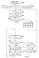
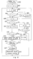
- Fig. 2 is a flowchart illustrating the operations of the control device 3.
- an engine throttle valve opening degree indicating value S and a brake fluid pressure indicating value B are initialized to zero at a step 901.
- an accelerator pedal treading force/displacement F detected by the device 2 is read (902).
- the detected value F is compared in size with a predetermined set value F c1 (greater than zero). If the detected value F is equal to or smaller than F c1 , the sequence proceeds to a step 906.
- the throttle valve drive device 4 is operated to open the throttle valve according to the opening degree proportional to this indicating value S within a range that the throttle valve is not fully opened.
- the indicating value S is increased such that the throttle valve is fully opened, the throttle valve remains fully opened even though the indicating value S is further increased.
- k s is a positive proportional coefficient
- F c3 is smaller than F c1 and is a positive constant near zero.
- the detected value F is compared in size with a preset value F c2 which is a constant greater than F c1 .
- F c2 a preset value
- the brake fluid pressure generator 6 generates a brake fluid pressure in proportion to this indicating value B.
- the detected value F is read. The sequence is then returned to the step 908.
- step 910 when F is equal to or smaller than F c2 , the sequence proceeds to a step 914, where B is set to zero. This indicates that the brake fluid pressure is to be released.
- step 916 F is compared in size with F c3 . When F is equal to or greater than F c3 , the sequence proceeds to a step 913. When F is smaller than F c3 , the sequence is returned to the step 902.
- the constant k s is set such that the throttle valve is fully opened when, with respect to the constant F c1 , the throttle valve opening degree indicating value S is greater than k s (F c4 - F c3 ) or greater than a value slightly smaller than k s (F c4 - F c3 ). This is also applied to embodiments of the present invention discussed in the following.
- Fig. 3 shows a block diagram of an embodiment of apparatus in accordance with Claim 2.
- reaction force generating means 8 is added to the embodiment shown in Fig. 1.
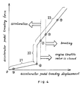
- reaction force generating means 8 there is established the relationship between the accelerator pedal treading force and the accelerator pedal treading displacement, as shown in Fig. 4.
- the treading force is suddenly increased (decreased) as compared with respect to increase (decrease) in treading displacement, at the level of treading force or treading displacement slightly smaller than the treading force or treading displacement which causes the engine throttle valve to be closed.
- the driver may feel such sudden increase, causing him to become aware of the fact that the throttle valve is now about to be closed.
- Fig. 5 shows an example of an accelerator pedal incorporating this reaction force generating means.
- an accelerator pedal 30 has a fulcrum 31 at which the arm of the accelerator pedal 30 is rotatably secured to the vehicle body.
- a return spring 32 for the arm of the accelerator pedal 30.
- Supports 33 are fixedly connected to the vehicle body.
- a spring 34 has repelling power stronger than that of the return spring 32.
- the spring 34 is disposed as compressed.
- a flange 35 is disposed for compressing the spring 34.
- a rod 36 is disposed for transmitting the displacement of the accelerator pedal 30 to the treading displacement detector.
- a flange 37 is fixedly connected to the rod 36 for pushing the flange 35.
- a support member 38 is disposed for determining the position in which the accelerator pedal 30 is located when released. When the accelerator pedal 30 is trodden, the rod 36 is displaced.
- Fig. 4 Shown in Fig. 4 are positions 1 to 4 on the curve corresponding to first to fourth predetermined treading force/displacement values set forth in Claims. Further shown in Fig. 4 is a position 5 corresponding to a fifth predetermined treading force/displacement value, to be discussed later.
- control device 3 in this embodiment is shown in the form of a flowchart in Fig. 2.
- the throttle valve opening degree indicating value S is greater than k s (F c4 - F c3 ) or greater than a value slightly smaller than k s (F c4 - F c3 ).
- FIG. 1 An embodiment of apparatus in accordance with Claim 3 is shown in the form of a block diagram in Fig. 1 or 3.
- Figs. 6 and 7 show, in the form of a flowchart, the operations of a control device 3 of the apparatus of Claim 3.
- added to the apparatus of Claim 1 is a function of delaying, by a predetermined period of time, the opening of the engine throttle valve in response to the accelerator pedal treading.
- the variables are initialized at a step 202. That is, an engine throttle valve opening degree indicating value S, a brake fluid pressure indicating value B, a variable t corresponding to the number of iteration times, and a variable F(0) are set to zero.
- the variable t is renewed to (t+1).
- a treading force/displacement detected value F is read.
- the detected value F is compared with the preset value F c1 . When the detected value F is greater than F c1 , the sequence proceeds to a step 216.
- the engine throttle valve opening degree indicating value S is renewed to zero, thereby to instruct that the throttle valve is to be closed.
- the subsequent steps on and after the step 216 are the same as those on and after the step 908 in Fig. 2.
- the sequence proceeds to a time delay sub-routine 212.
- Fig. 7 shows, in the form of a flowchart, this time delay sub-routine.
- a variable F(t) is set to the detected value F at a step 302.
- a predetermined positive constant ⁇ is compared with (t- ⁇ ) and zero.
- ⁇ corresponds to a delay time added to the response time during which the control device 3 instructs the opening of the engine throttle valve in response to the accelerator pedal treading.
- step 304 when (t- ⁇ ) is equal to and smaller than zero, the sequence proceeds to a step 306.
- the value of k s (F(0) - F c3 ) is given to a variable S1, which is then stored.
- the sequence proceeds to a step 308.
- the value k s (F(t- ⁇ ) - F c3 ) is given to the variable S1, which is then stored.
- the sequence proceeds to a step 310, where the value k s (F(t) - F c3 ) is given to a variable S2, which is then stored.
- the value S1 is compared with the value S2.
- the engine throttle valve opening degree indicating value S is set to the value of the variable S2.
- the sequence proceeds to a step 315, where the variable F(t) is compared in size with F(t-1). If F(t) is greater than F(t-1), the sequence proceeds to a step 316, where the variable F(0) is renewed to the value F(t-1). Then, the variable t is renewed to zero, and the sequence proceeds to a step 322, where this sub-routine is finished.
- step 315 if F(t) is equal to or smaller than F(t-1), the sequence proceeds to the step 322, where this sub-routine is finished.
- step 312 when S1 is smaller than S2, the engine throttle valve opening degree indicating value S is set to the value of the variable S1 at a step 320. Then, the sequence proceeds to the step 322, where this sub-routine is finished. When the sub-routine is finished at the step 322, the sequence is returned to the step 204, as shown in Fig. 6.
- T is the response delay time above-mentioned.
- FIG. 1 An embodiment of apparatus in accordance with Claim 4, 5, or 6 is shown in the form of a block diagram in Fig. 1, 3, 10 or 14.
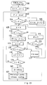
- the operations of a control device 3 in this embodiment are shown in the form of a flowchart in Fig. 8, in which the characteristic function of the apparatus of Claim 4, 5 or 6 is added to the apparatus of Claim 1.
- a detected value F is compared with a predetermined set value F c5 which is a constant set to a predetermine value greater than the preset value F c2 .
- F c5 a predetermined set value
- the sequence proceeds to a step 417, where the detected value F is read. Then, the sequence is returned to a step 408.
- the sequence proceeds to a step 420, where a brake fluid pressure indicating value B is set to a maximum value B max . Accordingly, the brake fluid pressure generator 6 provides a maximized brake fluid pressure. Then, the sequence proceeds to a maximized-brake release routine 422.
- the detected value F is compared in size with the preset value F c3 . When F is smaller than F c3 , the sequence is returned to a step 402, and when F is equal to or greater than F c3 , the sequence proceeds to a step 417.
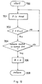
- FIG. 9, 11 or 12 An example of the maximized-brake release routine 422 is shown in Fig. 9, 11 or 12.
- the apparatus of Claim 4 is characterized in that a brake pedal treading force/displacement detector 14 is added to the arrangement of the apparatus of Claim 1 shown in Fig. 1.
- the control device 3 is adapted to read not only an accelerator pedal treading force/displacement detected value, but also a brake pedal treading force/displacement detected value, thereby to control the engine throttle valve, as well as the brakes.
- the apparatus of Claim 5 having a maximized-brake release routine described in the flowchart in Fig. 11, is shown in the form of a block diagram in, for example, Fig. 1 or 3.
- the apparatus of Claim 6 having a maximized-brake release routine described in the flowchart in Fig. 12, is shown in the form of a block diagram in, for example, Fig. 14.
- a switch operable by the driver is added to the arrangement shown by the block diagram in Fig. 1.
- the control device 3 is adapted to detect the operational state of the switch by an electric signal.
- the detected value F is read at a step 501.
- the detected value F is compared with the preset value F c3 .
- the sequence is returned to the step 501.
- F is smaller than F c3 , the sequence proceeds to a step 503, where a brake pedal treading force/displacement detected value D is read.
- the detected value D is compared with a predetermined set value D c which is greater than zero but near zero.
- the sequence is returned to the step 501.
- step 506 When D is greater than D c , the sequence proceeds to a step 506, where a brake fluid pressure indicating value B is set to zero. The sequence proceeds to a step 508, where this routine is finished. Then, the sequence is returned to the step 402 in Fig. 8. That is, the accelerator pedal is released and the brake pedal is trodden to a certain extent, thereby to release the state where the maximized brakes are applied.
- the maximized-brake release routine starts at a step 600, and a detected value F is read at a step 601.
- the detected value F is compared with the preset value F c3 .
- the sequence is returned to the step 601.
- F is smaller than F c3
- the sequence proceeds to a step 604, where the indicating value B is set to zero.
- this routine is finished, and the sequence is returned to the step 402 in Fig. 8. That is, when the accelerator pedal is released, there is released the state where the maximized brakes are applied.
- the maximized-brake release routine starts at a step 700, and a detected value F is read at a step 701.
- the detected value F is compared with the preset value F c3 .
- the sequence is returned to the step 701.
- F is smaller than F c3
- the sequence proceeds to a step 704, where the release switch is checked for operational state.
- the release switch has not been turned ON, the sequence is returned to the step 701.
- the release switch has been turned ON, the sequence proceeds to a step 706, where the brake fluid pressure indicating value B is set to zero.
- the sequence proceeds to a step 708, where this routine is finished.
- the sequence is returned to the step 402 in Fig. 8. That is, when the accelerator pedal is released and the specified release switch is operated, there is released the state where the maximized brakes are applied.
- FIG. 13 is the same as that in Fig. 8, except that the step 418 in Fig. 8 is replaced with steps 113, 115, 118 and 119 in Fig. 13.
- the sequence proceeds to the step 113, where a variable k is initialized to zero.
- a treading force/displacement detected value F is compared in size with the preset value F c5 .
- the sequence proceeds to a step 117.
- the sequence proceeds to the step 118, where the variable k is incremented by +1.
- the sequence then proceeds to the step 119, where the variable k is compared in size with a predetermined preset positive value K.
- the varialbe k is equal to or smaller than the constant K, the sequence is returned to the step 115.
- k is greater than K, the sequence proceeds to a step 120.
- ⁇ 1 is the time during which the sequence makes a round of a loop starting from and returning to the step 115 through the steps 118, 119.
- FIG. 9, 11 or 12 An example of the maximized-brake release routine 122 is shown in Fig. 9, 11 or 12.
- the apparatus having a maximized-brake release routine described in the flowchart in Fig. 9, is shown in the form of a block diagram in, for example, Fig. 10.
- the apparatus having a maximized-brake release routine described in the flowchart in Fig. 11, is shown in the form of a block diagram in, for example, Fig. 1 or 3.
- the apparatus having a maximized-brake release routine described in the flowchart in Fig. 12 is shown in the form of a block diagram in, for example, Fig. 14.
- FIG. 8 An embodiment of apparatus of Claim 8 is shown in the form of a block diagram including a shock sensor added to the arrangement shown in Fig. 1, 3, 10 or 14.
- FIG. 15 An example of such block diagram is shown in Fig. 15, in which a shock sensor 16 is added to the block diagram in Fig. 1 illustrating the embodiment of apparatus of Claim 1.
- Fig. 16 shows a flowchart of the operations of the control device 3 in this embodiment.
- an accelerator pedal treading force/displacement detected value F is compared in size with the predetermined preset value F c5 of accelerator pedal treading force/displacement set forth in the embodiment of apparatus of Claim 4, 5 or 6.
- the sequence proceeds to a step 817.
- the sequence proceeds to a step 819.
- an output signal from the shock sensor 16 is read.
- the contents of the output signal thus read are checked. When this output signal represents that the shock sensor has detected no shock, the sequence proceeds to a step 817.
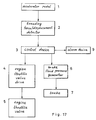
- FIG. 17 An embodiment of apparatus of Claim 9 is shown in the form of a block diagram in Fig. 17. This embodiment is arranged such that an alarm device 9 is driven when a control device 3 indicates a maximized-brake state.
- the alarm device 9 includes (a) a buzzer, (b) flash lamps, (c) lightings or (d) tail lamps and indicators.
- the buzzer is so arranged as to sound inside or outside of the motor vehicle.
- the flash lamps and lightings are so arranged as to flicker, and the tail lamps and indicators are so arranged as to simultaneously flicker.
- An example of the operations of the control device 3 is arranged such that the controls device 3 indicates an actuation of the alarm device at the same time when the indicating value B is set to the maximized value B max , for example, at the step 420 in Fig. 8, and that the control device 3 indicates a release of the actuation of the alarm device at the same time when the maximized-brake release routine is finished at the step 422.
- the actuation of the alarm device the fact that the motor vehicle is under emergent stop may be informed inside and outside of the motor vehicle. This enhances the safety.
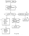
- FIG. 18 An embodiment of apparatus of Claim 10 is shown in the form of a block diagram in Fig. 18.
- an anti-lock brake (ABS) fluid pressure control device 10 is incorporated, instead of the brake fluid pressure generator 6, in the block diagram of the embodiment of apparatus of Claim 1 in Fig. 1.
- ABS anti-lock brake
- the brakes are applied through an ABS fluid pressure control device 10 according to an indicating value of a control device 3.
- the brakes are so controlled as to prevent the wheels from being fixed (locked).
- the ABS fluid pressure control device is known per se.
- the brakes may be applied with a maximum friction with respect to the road surface, while assuring the steering ability. This is a particularly important function in view of improvement in safety.
- FIG. 19 An embodiment of apparatus of Claim 11 is shown in the form of a block diagram in Fig. 19, in which a clutch drive device 11 is added to the block diagram of the apparatus of Claim 1 in Fig. 1.
- a control device 3 not only controls the engine throttle valve and the brakes, but also a clutch 12.
- control device 3 instructs the clutch drive device to separate the clutch at the same time when the engine throttle valve opening degree indicating value S is set to zero, for example, at the step 908 in the flowchart in Fig. 2. Further, when a judgement YES is obtained at the step 916, the control device 3 instructs the clutch drive device to connect the clutch at the step just before the sequence is returned to the step 902.
- the apparatus of each of Claims 1 to 11 is so arranged as not to prevent a normal braking operation by the brake pedal.
- the brake fluid pressure unit is composed of two systems, i.e., a first system for generating a fluid pressure by the brake pedal and the master cylinder, and a second system for generating a fluid pressure by the apparatus of each of Claims 1 to 11. Both systems may apply the brakes.
- the brake pedal may serve as a normal brake pedal even though the brake fluid pressure indicating value B is set to, for example, zero by the control device 3.
- the apparatus of Claim 11 is so arranged as not to prevent a clutch disconnection operation by the clutch pedal.
- the clutch drive unit includes two systems, i.e., a first drive system by the apparatus of Claim 11 and a second drive system by the clutch pedal. Any of both systems may disconnect the clutch.
- Such arrangement of the clutch drive unit may be readily made according to prior arts. Accordingly, when the control device 3 of the apparatus of, for example, Claim 11 instructs to connect the clutch, the clutch pedal may serve as a normal clutch pedal.
Description
- The present invention relates to a motor vehicle braking apparatus according to the preamble of
claim 1 using accelerator pedal arranged such that the brakes are applied when the accelerator pedal of a motor vehicle is trodden with a treading force/displacement not smaller than a predetermined value. - In a motor vehicle, the brakes are conventionally applied with the use of the brake pedal and the parking brake both independent from the accelerator pedal. In case of emergency, there often happens accidents due to an erroneous treading of the accelerator pedal instead of the brake pedal to be properly trodden, or due to the fact that the motor vehicle still travels without braking before the driver changes the pedal to be trodden from the accelerator pedal to the brake pedal and the driver actually treads the brake pedal. To avoid such accidents, there have been proposed a number of inventions relating to a pedal structure arranged such that one pedal serves as both accelerator pedal and brake pedal as is disclosed in DE-A-2 638 144, according to which the preamble of
claim 1 has been drafted, and further in Japanese Patent Laid-Open Publications JP-A-49016127 and JP-A-49061826, Japanese Utility Model Laid-Open Publications JP-U-56064826, JP-U-57048131 and JP-U-59072130. These inventions have been proposed with the object of achieving both accelerator and brake functions by treading the same pedal, not only in case of emergency, but also at normal conditions. These structures are arranged such that the accelerator and brake functions are respectively selected according to different positions at which the driver applies a treading force to the same pedal. However, it is not always easy for the driver to select either function by properly treading the same pedal. Accordingly, these inventions may not duly constitute a solution for avoiding the danger that the driver erroneously treads the pedal when applying the brakes in case of emergency. - The Japanese Patent Laid-Open Publication JP-A-54-155529 discloses an apparatus in which the accelerator pedal treading force and treading speed are detected, and in which, if the pedal is once trodden with a treading force or a treading speed equal to or greater than a predetermined value, the engine throttle valve is thereafter closed in a continuous manner to apply the brakes, causing the motor vehicle to be emergently stopped. Further, the Japanese Utility Model Laid-Open Publication JP-U-61-47762 applied by the same applicant, discloses an apparatus in which the engine accelerator is continuously stopped upon detection of an accelerator pedal speed or acceleration speed equal to or greater than a predetermined value, and in which, upon detection of a treading displacement equal to or greater than a predetermined value, the brakes are continuously applied to emergently stop the motor vehicle.
- According to these inventions, after the accelerator pedal treading force, displacement, speed, acceleration speed or the like has reached a predetermined value, the state where engine acceleration is stopped, is maintained to apply the brakes even though the factor above-mentioned thereafter becomes below the predetermined value concerned. Such application of the brakes is continued until a specified release operation is carried out, for example, by turning OFF the ignition switch (Japanese Patent Laid-Open Publication JP-A-54-155529), or by once releasing the accelerator pedal and treading it again (Japanese Utility Model Publication JP-U-61-47762). According to these inventions, the motor vehicle may be automatically stopped even though, after the driver has carried out an emergent operation when it is required to emergently stop the motor vehicle, he falls, due to an accident or the like, into the state where he cannot further operate the motor vehicle. This enables the motor vehicle to be securely stopped in case of emergency. However, these apparatus also involve the likelihood that, when the accelerator pedal is suddenly strongly or deeply trodden with the intention of, for example, rapid acceleration at the time it is not required to emergently stop the motor vehicle, the emergent brakes are applied to provoke an accident.
- The Japanese Utility Model JP-U-61-47762 discloses, as an embodiment of the invention, a mechanism incorporating a spring adapted to start compression at a position slightly higher than the accelerator pedal displacement position at which the emergent brakes are applied. By such provision, the driver may become aware of the emergent braking start position. However, it is also difficult that such provision securely prevents the driver from erroneously treading the pedal.
- In view of the foregoing, the present invention is proposed with the object of providing an emergent braking apparatus for a motor vehicle which overcomes the defects of the conventional inventions above-mentioned.
- The present invention provides a motor vehicle braking apparatus using accelerator pedal having a characteristic set forth in any of appended
Claims 1 to 11. - Apparatus of
Claim 1 is operated as outlined below. - The accelerator pedal is adapted to serve as a normal accelerator pedal when the driver treads it with a treading force/displacement equal to or smaller than a predetermined value. If the driver further treads the accelerator pedal with a treading force/displacement greater than the predetermined value, the engine throttle valve is closed. If the accelerator pedal is further trodden to an extent exceeding a predetermined limit, the brakes are applied. The braking force is adjusted according to the depth to which the accelerator pedal is trodden. When the accelerator pedal is trodden to an extent exceeding the predetermined limit, the accelerator pedal serves as a brake pedal. When the accelerator pedal treading is released to an extent exceeding a predetermined limit, the application of the brakes is released. However, the engine throttle valve still remains closed. After the accelerator pedal treading force has been released to an extent near the level where the pedal is fully released, the accelerator pedal serves as a normal accelerator pedal.
- As compared with a conventional system in which the function of either accelerator or brake is selected according to the position at which the treading force is applied to the pedal, the system of the present invention is simpler in operation since such function is selected according to the treading force or depth applied to the same position. Accordingly, this reduces the likelihood that the driver erroneously treads the pedal in case of emergency. According to the apparatus of the present invention, the same accelerator pedal may be used for applying the brakes not only in case of emergency, but also at normal conditions.
- Apparatus of
Claim 2 additionally includes reaction force generating means arranged such that the accelerator pedal reaction force is suddenly increased when the accelerator pedal is trodden, in the apparatus ofClaim 1, from the treading force/depth level at which the accelerator pedal serves as a normal accelerator pedal, to the treading force/depth level slightly smaller/shallower than the treading force/depth level at which the engine throttle valve is closed. According to this apparatus, a sudden increase in accelerator pedal reaction force enables the driver to become aware, more securely than the conventional invention (Japanese Utility-Model Laid-Open Publication JP-U-61-47762), of the fact that the accelerator pedal is currently brought to a state immediately before the state where it loses the function of a normal accelerator pedal. This eliminates the danger that the driver erroneously treads the pedal when he has no intention of applying the brakes. - Apparatus of
Claim 3 is arranged such that, when the accelerator pedal is trodden, in the apparatus ofClaim - Apparatus of
Claim Claim 1, the accelerator pedal is further trodden strongly or deeply to an extent exceeding a predetermined limit where the accelerator pedal serves as a brake pedal, the maximized brakes are applied and such application is continued until a predetermined release operation is carried out. More specifically, the motor vehicle may be emergently stopped by treading the accelerator pedal strongly or deeply. According to the apparatus, there is provided a treading range where the braking force varies with the accelerator pedal treading force or depth and where the accelerator pedal serves as a normal brake pedal, before the maximized brakes are applied. This reduces the danger that the driver erroneously treads the pedal to brake the motor vehicle to an unnecessary emergent stop. - Apparatus of
Claim 7 is arranged such that, when the accelerator pedal is trodden, in the apparatus ofClaim - The apparatus of
Claim 7 achieves operational effects similar to those of the apparatus ofClaim Claim 7, when, after the driver has erroneously trodden, against his own will, the accelerator pedal so strongly or deeply that the maximized brakes are applied, the accelerator pedal treading force is weakened in a short period of time, the application of the maximized brakes is not continued. This further reduces the danger of unnecessary emergent stop due to erroneous pedal treading. - Apparatus of
Claim 8 further includes, in the apparatus ofClaim Claim 8, if a considerable shock is exerted to the motor vehicle while the accelerator pedal is trodden strongly or deeply to an extent exceeding a predetermined limit that the accelerator pedal serves as a brake pedal, the maximized brakes are applied and such application is maintained until a predetermined release operation is carried out. - There are instances where, even though the driver becomes aware of a danger during travelling and treads, with intent to emergently stop the vehicle, the accelerator pedal so strongly or deeply as to apply the maximized brakes, the motor vehicle accidently comes in collision with a forward obstacle or the like, disabling the driver from further operating the vehicle. In such a case, the apparatus of
Claim 8 may detect the shock exerted at the time of collision so that the application of the maximized brakes is maintained to automatically stop the motor vehicle. Further, when the driver erroneously treads, against his own will, the accelerator pedal so strongly or deeply as to apply the maximized brakes and, at that time, no shock is exerted to the motor vehicle due to collision or the like, the accelerator pedal treading force may be weakened so that the application of the maximized brakes is not maintained. This reduces the likelihood that an erroneous pedal treading results in unnecessary emergent stop. - Apparatus of
Claim 9 further includes, in the apparatus ofClaim Claim 9, if the maximized brakes are applied, the fact that the motor vehicle is under emergent stop may be automatically informed both inside and outside of the vehicle. - According to apparatus of
Claim 10, the brakes are applied, in the apparatus ofClaim Claim - Apparatus of
Claim 11 is arranged such that, when the accelerator pedal is trodden, in the apparatus ofClaim - According to the motor vehicle braking apparatus of the present invention, the driver is not required to change the pedal to be trodden, from the accelerator pedal to the brake pedal, when applying the brakes to the motor vehicle in case of emergency. This not only reduces the distance of vehicle travelling made while such pedal change is carried out, but also prevents an accident due to erroneous pedal treading. Further, when intended to reduce the vehicle speed during normal travelling, the driver may apply the brakes with the use of the same accelerator pedal. This is particularly convenient when frequent braking and acceleration are repeatedly required. Further, the apparatus of the present invention may reduce the likelihood that the driver erroneously applies the brakes even though he intends to carry out acceleration.
-
- Figure 1 is a block diagram of an embodiment of apparatus in accordance with
Claim 1; - Figure 2 is a flowchart illustrating the operations of a control device in the embodiment of apparatus in Figure 1;
- Figure 3 is a block diagram of an embodiment of apparatus in accordance with
Claim 2; - Figure 4 illustrates the relationship between accelerator pedal treading force and accelerator pedal treading displacement in the apparatus in accordance with
Claim 2; - Figure 5 is a side view of an example of accelerator pedal reaction force generating means in the apparatus in accordance with
Claim 2; - Figure 6 is a flowchart illustrating the operations of a control device in an embodiment of apparatus in accordance with
Claim 3; - Figure 7 is a flowchart of a time delay sub-routine used in the flowchart shown in Figure 6;
- Figure 8 is a flowchart illustrating the operations of a control device in an embodiment of apparatus in accordance with
Claim - Figure 9 is a flowchart of an example of a maximized-brake release routine used in the flowchart shown in Figure 8, in connection with the apparatus in accordance with
Claim 4; - Figure 10 is a block diagram of the apparatus in accordance with
Claim 4, in which the control device is operated according to the flowchart shown in Figure 8 and the maximized-brake release routine is described according to the flowchart shown in Figure 9; - Figure 11 is a flowchart of an example of the maximized-brake release routine used in the flowchart shown in Figure 8, in connection with the apparatus of
Claim 5; - Figure 12 is a flowchart of another example of the maximized-brake release routine used in the flowchart shown in Figure 8, in connection with the apparatus in accordance with
Claim 6; - Figure 13 is a flowchart of the operations of a control device in an embodiment of apparatus in accordance with
Claim 7; - Figure 14 is a block diagram of the apparatus in accordance with
Claim 6, in which the control device is operated according to the flowchart shown in Figure 8 and the maximized-brake release routine is described according to the flowchart shown in Figure 12; - Figure 15 is a block diagram of an embodiment of apparatus in accordance with
Claim 8; - Figure 16 is a flowchart illustrating the operations of a control device in an embodiment of the apparatus in accordance with
Claim 8; - Figure 17 is a block diagram of an embodiment of apparatus in accordance with
Claim 9; - Figure 18 is a block diagram of an embodiment of apparatus in accordance with
Claim 10; and - Figure 19 is a block diagram of an embodiment of apparatus in accordance with
Claim 11. - Fig. 1 shows a block diagram of an embodiment of apparatus in accordance with
Claim 1. In Fig. 1, component elements designated by 1, 2, 4, 5, 6 and 7 may be readily arranged according to prior arts, or they are known per se. - A
control device 3 is composed of an electronic circuit including a micro-processor, a memory and an input/output interface, and is adapted to be operated according to a program previously written in the memory. A treading force/displacement detector 2 is operatively connected to anaccelerator pedal 1 for detecting a treading force/displacement. The treading force/displacement detector 2 may be readily formed by a load sensor, a potentiometer and the like known per se. Thecontrol device 3 is adapted to read a detection signal (for example, a signal converted into a voltage) supplied from the treading force/displacement detector 2. Based on the signal thus read, thecontrol device 3 supplies an electric signal (for example, a voltage signal) for instructing the operations of an enginethrottle valve drive 4 and a brakefluid pressure generator 6. Based on the signal thus supplied from thecontrol device 3, the engine throttlevalve drive device 4 and the brakefluid pressure generator 6 respectively drive anengine throttle valve 5 andbrakes 7. The throttlevalve drive device 4 comprises an actuator for converting an electric signal (for example, a voltage signal) supplied from thecontrol device 3 into a mechanical operation for driving the throttle valve. The throttlevalve drive device 4 may be readily arranged according to prior arts. The brakefluid pressure generator 6 is adapted to convert an electric signal (for example, a voltage signal) supplied from thecontrol device 3, into a brake fluid pressure for driving the brakes. The brakefluid pressure generator 6 is also a kind of an actuator known per se. - Fig. 2 is a flowchart illustrating the operations of the
control device 3. When the engine key is turned ON (900), an engine throttle valve opening degree indicating value S and a brake fluid pressure indicating value B are initialized to zero at astep 901. Then, an accelerator pedal treading force/displacement F detected by thedevice 2 is read (902). At astep 904, the detected value F is compared in size with a predetermined set value Fc1 (greater than zero). If the detected value F is equal to or smaller than Fc1, the sequence proceeds to astep 906. The engine throttle valve opening degree indicating value S (for example, a voltage output) to be transmitted to the throttlevalve drive device 4, is set to
valve drive device 4 is operated to open the throttle valve according to the opening degree proportional to this indicating value S within a range that the throttle valve is not fully opened. When the indicating value S is increased such that the throttle valve is fully opened, the throttle valve remains fully opened even though the indicating value S is further increased. In the equation above-mentioned, ks is a positive proportional coefficient, and Fc3 is smaller than Fc1 and is a positive constant near zero. The sequence is then returned to thestep 902. At thestep 904, when the detected value F is greater than Fc1, the sequence proceeds to astep 908, where S is set to zero. This indicates that the engine throttle valve is to be closed. - At a
step 910, the detected value F is compared in size with a preset value Fc2 which is a constant greater than Fc1. When F is greater than Fc2, the sequence proceeds to astep 912. The indicating value B for indicating the value of a liquid pressure to the brakefluid pressure generator 6, is set to
fluid pressure generator 6 generates a brake fluid pressure in proportion to this indicating value B. At astep 913, the detected value F is read. The sequence is then returned to thestep 908. At astep 910, when F is equal to or smaller than Fc2, the sequence proceeds to astep 914, where B is set to zero. This indicates that the brake fluid pressure is to be released. At astep 916, F is compared in size with Fc3. When F is equal to or greater than Fc3, the sequence proceeds to astep 913. When F is smaller than Fc3, the sequence is returned to thestep 902. Preferably, the constant ks is set such that the throttle valve is fully opened when, with respect to the constant Fc1, the throttle valve opening degree indicating value S is greater than ks (Fc4 - Fc3) or greater than a value slightly smaller than ks (Fc4 - Fc3). This is also applied to embodiments of the present invention discussed in the following. - Fig. 3 shows a block diagram of an embodiment of apparatus in accordance with
Claim 2. - This embodiment is characterized in that reaction force generating means 8 is added to the embodiment shown in Fig. 1. By the reaction force generating means 8, there is established the relationship between the accelerator pedal treading force and the accelerator pedal treading displacement, as shown in Fig. 4. The treading force is suddenly increased (decreased) as compared with respect to increase (decrease) in treading displacement, at the level of treading force or treading displacement slightly smaller than the treading force or treading displacement which causes the engine throttle valve to be closed. In the middle course of accelerator pedal treading, the driver may feel such sudden increase, causing him to become aware of the fact that the throttle valve is now about to be closed.
- Fig. 5 shows an example of an accelerator pedal incorporating this reaction force generating means.
- In Fig. 5, an
accelerator pedal 30 has a fulcrum 31 at which the arm of theaccelerator pedal 30 is rotatably secured to the vehicle body. There is disposed areturn spring 32 for the arm of theaccelerator pedal 30.Supports 33 are fixedly connected to the vehicle body. Aspring 34 has repelling power stronger than that of thereturn spring 32. Thespring 34 is disposed as compressed. Aflange 35 is disposed for compressing thespring 34. Arod 36 is disposed for transmitting the displacement of theaccelerator pedal 30 to the treading displacement detector. Aflange 37 is fixedly connected to therod 36 for pushing theflange 35. Asupport member 38 is disposed for determining the position in which theaccelerator pedal 30 is located when released. When theaccelerator pedal 30 is trodden, therod 36 is displaced. While this displacement is small, the pedal reaction force is generated by thespring 32 having weaker repelling power. As the treading displacement is increased, the reaction force is gradually increased. This corresponds to anarea 21 of the curve in Fig. 4. When the pedal is further trodden, theflange 37 fixedly attached to therod 36 comes in contact with theflange 35 which maintains thespring 34, as compressed, of which repelling power is stronger than that of thespring 32. This causes the compression force of thespring 34 to be transmitted to theflange 37. Accordingly, the accelerator pedal reaction force is suddenly increased, in a discontinuous manner, with respect to the displacement. This is represented by anarea 22 of the curve in Fig. 4. - When the
accelerator pedal 30 is further trodden, the accelerator pedal reaction force is increased according to the increase in the restoring forces of thesprings area 23 of the curve in Fig. 4. - Shown in Fig. 4 are
positions ① to ④ on the curve corresponding to first to fourth predetermined treading force/displacement values set forth in Claims. Further shown in Fig. 4 is aposition ⑤ corresponding to a fifth predetermined treading force/displacement value, to be discussed later. - The operation of a
control device 3 in this embodiment is shown in the form of a flowchart in Fig. 2. - According to this embodiment having the accelerator pedal reaction force generating means, it is desired to set the constant ks such that the throttle valve is fully opened when, with respect to a treading force/displacement value Fc4 provoking a sudden increase in accelerator pedal reaction force, the throttle valve opening degree indicating value S is greater than ks (Fc4 - Fc3) or greater than a value slightly smaller than ks (Fc4 - Fc3). This is also applied to all embodiments of the present invention shown in the following, as far as the accelerator pedal reaction force generating means is incorporated.
- An embodiment of apparatus in accordance with
Claim 3 is shown in the form of a block diagram in Fig. 1 or 3. Figs. 6 and 7 show, in the form of a flowchart, the operations of acontrol device 3 of the apparatus ofClaim 3. In this embodiment, added to the apparatus ofClaim 1, is a function of delaying, by a predetermined period of time, the opening of the engine throttle valve in response to the accelerator pedal treading. - As shown in Fig. 6, when the engine key is turned ON (200), the variables are initialized at a
step 202. That is, an engine throttle valve opening degree indicating value S, a brake fluid pressure indicating value B, a variable t corresponding to the number of iteration times, and a variable F(0) are set to zero. At astep 204, the variable t is renewed to (t+1). At astep 206, a treading force/displacement detected value F is read. At astep 208, the detected value F is compared with the preset value Fc1. When the detected value F is greater than Fc1, the sequence proceeds to astep 216. At thestep 216, the engine throttle valve opening degree indicating value S is renewed to zero, thereby to instruct that the throttle valve is to be closed. The subsequent steps on and after thestep 216, are the same as those on and after thestep 908 in Fig. 2. At thestep 208, when the detected value F is equal to or smaller than the preset value Fc1, the sequence proceeds to atime delay sub-routine 212. Fig. 7 shows, in the form of a flowchart, this time delay sub-routine. - When this sub-routine starts at a
step 300, a variable F(t) is set to the detected value F at astep 302. At astep 304, a predetermined positive constant τ is compared with (t-τ) and zero. Here, τ corresponds to a delay time added to the response time during which thecontrol device 3 instructs the opening of the engine throttle valve in response to the accelerator pedal treading. Where the processing time during which the sequence is made a round in a loop of thesteps 204 → 206 → 208 → 212 → 204, is expressed by Tc, the constant τ is given by
step 304, when (t-τ) is equal to and smaller than zero, the sequence proceeds to astep 306. At thestep 306, the value of ks (F(0) - Fc3) is given to a variable S₁, which is then stored. When the difference of (t -τ) is positive, the sequence proceeds to astep 308. At thestep 308, the value ks (F(t-τ) - Fc3) is given to the variable S₁, which is then stored. The sequence proceeds to a step 310, where the value ks (F(t) - Fc3) is given to a variable S₂, which is then stored. At astep 312, the value S₁ is compared with the value S₂. When S₁ is equal to or greater than S₂, the engine throttle valve opening degree indicating value S is set to the value of the variable S₂. The sequence proceeds to astep 315, where the variable F(t) is compared in size with F(t-1). If F(t) is greater than F(t-1), the sequence proceeds to astep 316, where the variable F(0) is renewed to the value F(t-1). Then, the variable t is renewed to zero, and the sequence proceeds to astep 322, where this sub-routine is finished. - At the
step 315, if F(t) is equal to or smaller than F(t-1), the sequence proceeds to thestep 322, where this sub-routine is finished. At thestep 312, when S₁ is smaller than S₂, the engine throttle valve opening degree indicating value S is set to the value of the variable S₁ at astep 320. Then, the sequence proceeds to thestep 322, where this sub-routine is finished. When the sub-routine is finished at thestep 322, the sequence is returned to thestep 204, as shown in Fig. 6. - According to this sub-routine, the engine throttle valve opening degree indicating value S(t) at the time t, is given by the equation


- An embodiment of apparatus in accordance with
Claim control device 3 in this embodiment are shown in the form of a flowchart in Fig. 8, in which the characteristic function of the apparatus ofClaim Claim 1. - The flow from a
step 400 to astep step 900 to thestep step 418 subsequent to thestep 412, a detected value F is compared with a predetermined set value Fc5 which is a constant set to a predetermine value greater than the preset value Fc2. When the detected value F is equal to or smaller than Fc5, the sequence proceeds to astep 417, where the detected value F is read. Then, the sequence is returned to astep 408. On the contrary, at thestep 418, when F is greater than Fc5, the sequence proceeds to astep 420, where a brake fluid pressure indicating value B is set to a maximum value Bmax. Accordingly, the brakefluid pressure generator 6 provides a maximized brake fluid pressure. Then, the sequence proceeds to a maximized-brake release routine 422. At astep 416, the detected value F is compared in size with the preset value Fc3. When F is smaller than Fc3, the sequence is returned to astep 402, and when F is equal to or greater than Fc3, the sequence proceeds to astep 417. - An example of the maximized-
brake release routine 422 is shown in Fig. 9, 11 or 12. The apparatus ofClaim 4 having a maximized-brake release routine described in the flowchart in Fig. 9, is shown in the form of a block diagram in, for example, Fig. 10. - The apparatus of
Claim 4 is characterized in that a brake pedal treading force/displacement detector 14 is added to the arrangement of the apparatus ofClaim 1 shown in Fig. 1. According to this apparatus ofClaim 4, thecontrol device 3 is adapted to read not only an accelerator pedal treading force/displacement detected value, but also a brake pedal treading force/displacement detected value, thereby to control the engine throttle valve, as well as the brakes. - The apparatus of
Claim 5 having a maximized-brake release routine described in the flowchart in Fig. 11, is shown in the form of a block diagram in, for example, Fig. 1 or 3. - The apparatus of
Claim 6 having a maximized-brake release routine described in the flowchart in Fig. 12, is shown in the form of a block diagram in, for example, Fig. 14. In Fig. 14, a switch operable by the driver is added to the arrangement shown by the block diagram in Fig. 1. Thecontrol device 3 is adapted to detect the operational state of the switch by an electric signal. - In the embodiment shown in Fig. 9, when the routine starts (500), the detected value F is read at a
step 501. At astep 502, the detected value F is compared with the preset value Fc3. When the detected value F is equal to or greater than Fc3, the sequence is returned to thestep 501. When F is smaller than Fc3, the sequence proceeds to astep 503, where a brake pedal treading force/displacement detected value D is read. At astep 504, the detected value D is compared with a predetermined set value Dc which is greater than zero but near zero. When the detected value D is equal to or smaller than Dc, the sequence is returned to thestep 501. When D is greater than Dc, the sequence proceeds to astep 506, where a brake fluid pressure indicating value B is set to zero. The sequence proceeds to astep 508, where this routine is finished. Then, the sequence is returned to thestep 402 in Fig. 8. That is, the accelerator pedal is released and the brake pedal is trodden to a certain extent, thereby to release the state where the maximized brakes are applied. - In the embodiment shown in Fig. 11, the maximized-brake release routine starts at a
step 600, and a detected value F is read at astep 601. At astep 602, the detected value F is compared with the preset value Fc3. When the detected value F is equal to or greater than Fc3, the sequence is returned to thestep 601. When F is smaller than Fc3, the sequence proceeds to a step 604, where the indicating value B is set to zero. At astep 606, this routine is finished, and the sequence is returned to thestep 402 in Fig. 8. That is, when the accelerator pedal is released, there is released the state where the maximized brakes are applied. - In the embodiment shown in Fig. 12, the maximized-brake release routine starts at a
step 700, and a detected value F is read at astep 701. At astep 702, the detected value F is compared with the preset value Fc3. When the detected value F is equal to or greater than Fc3, the sequence is returned to thestep 701. When F is smaller than Fc3, the sequence proceeds to astep 704, where the release switch is checked for operational state. When the release switch has not been turned ON, the sequence is returned to thestep 701. On the contrary, when the release switch has been turned ON, the sequence proceeds to astep 706, where the brake fluid pressure indicating value B is set to zero. The sequence proceeds to astep 708, where this routine is finished. Then, the sequence is returned to thestep 402 in Fig. 8. That is, when the accelerator pedal is released and the specified release switch is operated, there is released the state where the maximized brakes are applied. - Likewise the embodiment of apparatus of
Claim Claim 7 is shown in the form of a block diagram in Fig. 1, 3, 10 or 14. The operations of acontrol device 3 in this embodiment are shown in the form of a flowchart in Fig. 13. The flowchart in Fig. 13 is the same as that in Fig. 8, except that thestep 418 in Fig. 8 is replaced withsteps - Through the
step 112, the sequence proceeds to thestep 113, where a variable k is initialized to zero. At thestep 115, a treading force/displacement detected value F is compared in size with the preset value Fc5. When the detected value F is equal to or smaller than Fc5, the sequence proceeds to astep 117. When the detected value F is greater than Fc5, the sequence proceeds to thestep 118, where the variable k is incremented by +1. The sequence then proceeds to thestep 119, where the variable k is compared in size with a predetermined preset positive value K. When the varialbe k is equal to or smaller than the constant K, the sequence is returned to thestep 115. When k is greater than K, the sequence proceeds to astep 120. - According to this routine, there is provided a state where the maximized brakes are continuously applied when the treading force/displacement detected value F is greater than the predetermined preset value Fc5, continuously for a period of time of about τ₁ x K. Here, τ₁ is the time during which the sequence makes a round of a loop starting from and returning to the
step 115 through thesteps - An example of the maximized-
brake release routine 122 is shown in Fig. 9, 11 or 12. The apparatus having a maximized-brake release routine described in the flowchart in Fig. 9, is shown in the form of a block diagram in, for example, Fig. 10. The apparatus having a maximized-brake release routine described in the flowchart in Fig. 11, is shown in the form of a block diagram in, for example, Fig. 1 or 3. The apparatus having a maximized-brake release routine described in the flowchart in Fig. 12, is shown in the form of a block diagram in, for example, Fig. 14. - An embodiment of apparatus of
Claim 8 is shown in the form of a block diagram including a shock sensor added to the arrangement shown in Fig. 1, 3, 10 or 14. An example of such block diagram is shown in Fig. 15, in which ashock sensor 16 is added to the block diagram in Fig. 1 illustrating the embodiment of apparatus ofClaim 1. - If the motor vehicle comes in collision with an obstacle or the like and a considerable shock is exerted to the vehicle body, the shock sensor detects such a shock and supplies a detection signal to the
control device 3. Based on output signals from the treading force/displacement detector 2 and theshock sensor 16, thecontrol device 3 controls the engine throttle valve opening degree and the brake fluid pressure. Fig. 16 shows a flowchart of the operations of thecontrol device 3 in this embodiment. - At a
step 818, an accelerator pedal treading force/displacement detected value F is compared in size with the predetermined preset value Fc5 of accelerator pedal treading force/displacement set forth in the embodiment of apparatus ofClaim step 817. When the detected value F is greater than the preset value Fc5, the sequence proceeds to astep 819. At thestep 819, an output signal from theshock sensor 16 is read. At astep 820, the contents of the output signal thus read are checked. When this output signal represents that the shock sensor has detected no shock, the sequence proceeds to astep 817. On the contrary, when this output signal represents that the shock sensor has detected a shock, the sequence proceeds to astep 821. Except the addition of thesteps step 822 is shown, in more detailed, in Fig. 9, 11 or 12, likewise in the embodiment of apparatus ofClaim - An embodiment of apparatus of
Claim 9 is shown in the form of a block diagram in Fig. 17. This embodiment is arranged such that analarm device 9 is driven when acontrol device 3 indicates a maximized-brake state. Thealarm device 9 includes (a) a buzzer, (b) flash lamps, (c) lightings or (d) tail lamps and indicators. The buzzer is so arranged as to sound inside or outside of the motor vehicle. The flash lamps and lightings are so arranged as to flicker, and the tail lamps and indicators are so arranged as to simultaneously flicker. - An example of the operations of the
control device 3 is arranged such that thecontrols device 3 indicates an actuation of the alarm device at the same time when the indicating value B is set to the maximized value Bmax, for example, at thestep 420 in Fig. 8, and that thecontrol device 3 indicates a release of the actuation of the alarm device at the same time when the maximized-brake release routine is finished at thestep 422. By the actuation of the alarm device, the fact that the motor vehicle is under emergent stop may be informed inside and outside of the motor vehicle. This enhances the safety. - An embodiment of apparatus of
Claim 10 is shown in the form of a block diagram in Fig. 18. In Fig. 18, an anti-lock brake (ABS) fluidpressure control device 10 is incorporated, instead of the brakefluid pressure generator 6, in the block diagram of the embodiment of apparatus ofClaim 1 in Fig. 1. - According to this embodiment in Fig. 18, the brakes are applied through an ABS fluid
pressure control device 10 according to an indicating value of acontrol device 3. Within a range of the indicating value above-mentioned, the brakes are so controlled as to prevent the wheels from being fixed (locked). It is noted that the ABS fluid pressure control device is known per se. In particular, in the apparatus ofClaim - An embodiment of apparatus of
Claim 11 is shown in the form of a block diagram in Fig. 19, in which aclutch drive device 11 is added to the block diagram of the apparatus ofClaim 1 in Fig. 1. According to this embodiment, acontrol device 3 not only controls the engine throttle valve and the brakes, but also a clutch 12. - An example of the operations of the
control device 3 is arranged such that thecontrol device 3 instructs the clutch drive device to separate the clutch at the same time when the engine throttle valve opening degree indicating value S is set to zero, for example, at thestep 908 in the flowchart in Fig. 2. Further, when a judgement YES is obtained at thestep 916, thecontrol device 3 instructs the clutch drive device to connect the clutch at the step just before the sequence is returned to thestep 902. - The apparatus of each of
Claims 1 to 11 is so arranged as not to prevent a normal braking operation by the brake pedal. More specifically, the brake fluid pressure unit is composed of two systems, i.e., a first system for generating a fluid pressure by the brake pedal and the master cylinder, and a second system for generating a fluid pressure by the apparatus of each ofClaims 1 to 11. Both systems may apply the brakes. Such arrangement of the fluid pressure systems is readily made according to prior arts. Accordingly, the brake pedal may serve as a normal brake pedal even though the brake fluid pressure indicating value B is set to, for example, zero by thecontrol device 3. - The apparatus of
Claim 11 is so arranged as not to prevent a clutch disconnection operation by the clutch pedal. More specifically, the clutch drive unit includes two systems, i.e., a first drive system by the apparatus ofClaim 11 and a second drive system by the clutch pedal. Any of both systems may disconnect the clutch. Such arrangement of the clutch drive unit may be readily made according to prior arts. Accordingly, when thecontrol device 3 of the apparatus of, for example,Claim 11 instructs to connect the clutch, the clutch pedal may serve as a normal clutch pedal.
Claims (11)
- A motor vehicle braking apparatus for a vehicle having brakes operated by pressure of a brake fluid, an engine throttle valve, an accelerator pedal (1), a detector (2) for detecting a displacement of the accelerator pedal (1) of the vehicle; and a control device (3) for controlling the engine throttle valve opening degree and the brakes;
said control device (3) being arranged such that:
the accelerator pedal (1) serves as a normal accelerator pedal for increasing the opening degree of the engine throttle valve with increase in accelerator pedal displacement;
the engine throttle valve is closed when the displacement exceeds a first predetermined displacement value (Fc1);
the brake fluid pressure is increased, when the displacement exceeds a second predetermined displacement value (Fc2) which is greater than said first predetermined displacement value (Fc1); and
the brake fluid pressure is released when the displacement is smaller than said second predetermined displacement value (Fc2);
characterized in that
said control device (3) is arranged to detect at least one of a treading force and the displacement of said accelerator pedal (1), the treading force and the displacement being interrelated through a predetermined function;
when the treading force/displacement is detected to be greater than said second predetermined treading force/displacement value (Fc2), the brake fluid pressure is increased or decreased according to the value of the detected treading force/displacement;
the accelerator pedal (1) is so restored as to serve as a normal accelerator pedal when the treading force/displacement is smaller than a third predetermined treading force/displacement value (Fc3) which is smaller than said first value (Fc1) and causes the accelerator pedal (1) to be released; and
the engine throttle valve is maintained closed until the accelerator pedal (1) is so restored as to serve as a normal accelerator pedal. - The motor vehicle braking apparatus of Claim 1, further comprising accelerator pedal reaction force generating means arranged to provide treading force vs. displacement characteristics in which the treading force is suddenly increased as compared with increase in displacement, at a fourth predetermined treading force/displacement value which is lower than the first predetermined treading force/displacement value and higher than the third predetermined treading force/displacement value.
- The motor vehicle braking apparatus of Claim 1 or 2, wherein the control device is arranged such that, when the opening degree of the engine throttle valve is increased with increase in accelerator pedal treading force/displacement before the treading force/displacement becomes greater than the first predetermined treading force/displacement value, there is a predetermined time delay between the increase in treading force/displacement and the subsequent response of the engine throttle valve.
- The motor vehicle braking apparatus of Claim 1, further comprising a brake pedal treading force/displacement detector (14), wherein the control device (3) is arranged such that:(i) there is set a fifth predetermined accelerator pedal treading force/displacement value (fc5) higher than the second predetermined treading force/displacement value (Fc2);(ii) the brake fluid pressure is maximized when the accelerator pedal treading force/displacement becomes greater than said fifth preset value; and(iii) when the accelerator pedal treading force/displacement is smaller than the third predetermined treading force/displacement value (Fc3) and said brake pedal treading force/displacement detector (14) detects a predetermined brake pedal treading force/displacement value, the maximized brake fluid pressure is released so that the brake pedal (13) and the accelerator pedal (1) are so restored as to serve as a normal brake pedal and a normal accelerator pedal, respectively.
- The motor vehicle braking apparatus of Claim 1, wherein the control device is arranged such that:(i) there is set a fifth predetermined accelerator pedal treading force/displacement value (Fc5) higher than the second predetermined treading force/displacement value (Fc2);(ii) the brake fluid pressure is maximized when the accelerator pedal treading force/displacement becomes greater than said fifth preset value; and(iii) when the accelerator pedal treading force/displacement is smaller than the third predetermined treading force/displacement value (Fc3), the brake fluid pressure is released, causing the accelerator pedal (1) to be so restored as to serve as a normal accelerator pedal.
- The motor vehicle braking apparatus of Claim 1, further comprising a switch (15) operable by the driver, wherein the control device is arranged such that:(i) there is set a fifth predetermined accelerator pedal treading force/displacement value (Fc5) greater than the second predetermined treading force/displacement value (Fc2);(ii) the brake fluid pressure is maximized when the accelerator pedal treading force/displacement becomes greater than said fifth preset value; and(iii) when the accelerator pedal treading force/displacement is smaller than the third predetermined treading force/displacement value (Fc3) and said switch (15) is operated, the maximized brake fluid pressure is released, causing the accelerator pedal (1) to be so restored as to serve as a normal accelerator pedal.
- The motor vehicle braking apparatus of Claim 4, 5 or 6, wherein the control device is arranged such that the brake fluid pressure is maximized when the accelerator pedal treading force/displacement is continuously greater than the fifth preset value (Fc5) for a predetermined period of time.
- The motor vehicle braking apparatus of Claim 4, 5 or 6, further comprising a shock sensor (16) for detecting a shock, if any, exerted to the motor vehicle wherein the control device is arranged such that, when said shock sensor (16) supplies a detection signal at the time the accelerator pedal treading force/displacement is greater than the fifth preset value (Fc5), the brake fluid pressure is maximized from the point of time that said detection signal is supplied.
- The motor vehicle braking apparatus of Claim 4, 5 or 6, further comprising an alarm device (9), said alarm device being adapted to be actuated to give, at least either inside or outside of the motor vehicle, a sound or light alarm while there is continued the state of a maximized brake fluid pressure provoked by the fact that the accelerator pedal treading force/displacement has exceeded the fifth predetermined value.
- The motor vehicle braking apparatus of Claim 1, 2, 4, 5 or 6, further comprising an anti-lock braking device (10) arranged such that the brake fluid pressure is subjected to an anti-lock control when the brakes are applied.
- The motor vehicle braking apparatus of Claim 1, 2, 4, 5 or 6, further comprising a clutch drive device (11) adapted (i) to disconnect the clutch at the same time when the control device (3) closes the engine throttle valve when the accelerator pedal treading/displacement detector detects that the accelerator pedal treading force/displacement is greater than the first predetermined treading force/displacement value (Fc1), and (ii) to connect the clutch at the same time when the accelerator pedal (1) is so restored as to serve as a normal accelerator pedal.
Applications Claiming Priority (4)
| Application Number | Priority Date | Filing Date | Title |
|---|---|---|---|
| JP13322788 | 1988-10-11 | ||
| JP133227/88 | 1988-10-11 | ||
| JP96027/89 | 1989-04-15 | ||
| JP9602789 | 1989-04-15 |
Publications (2)
| Publication Number | Publication Date |
|---|---|
| EP0363634A1 EP0363634A1 (en) | 1990-04-18 |
| EP0363634B1 true EP0363634B1 (en) | 1995-11-29 |
Family
ID=26437248
Family Applications (1)
| Application Number | Title | Priority Date | Filing Date |
|---|---|---|---|
| EP89116388A Expired - Lifetime EP0363634B1 (en) | 1988-10-11 | 1989-09-05 | Motor vehicle braking apparatus using accelerator pedal |
Country Status (3)
| Country | Link |
|---|---|
| US (1) | US5007516A (en) |
| EP (1) | EP0363634B1 (en) |
| DE (1) | DE68924957T2 (en) |
Families Citing this family (19)
| Publication number | Priority date | Publication date | Assignee | Title |
|---|---|---|---|---|
| US5048655A (en) * | 1990-05-22 | 1991-09-17 | Deere & Company | Electric declutch mechanism for direct drive crawler |
| DE19753764A1 (en) * | 1997-12-04 | 1999-06-10 | Itt Mfg Enterprises Inc | Method and device for maneuvering motor vehicles |
| DE19943894B4 (en) * | 1998-10-14 | 2011-03-31 | Continental Teves Ag & Co. Ohg | Method for stabilizing the driving behavior |
| DE19922338A1 (en) | 1999-05-14 | 2000-11-23 | Bayerische Motoren Werke Ag | Method for establishing a predetermined operative relationship between the actuation of the accelerator pedal and the resulting braking torque of a vehicle |
| EP1792799A3 (en) * | 1999-07-01 | 2008-10-22 | Hitachi, Ltd. | Apparatus for controlling run of a car, and car using the apparatus |
| DE10205770B4 (en) * | 2002-02-12 | 2006-08-24 | Bayerische Motoren Werke Ag | A method for determining the predetermined by the driver of a motor vehicle wish for longitudinal vehicle dynamics |
| JP3651793B2 (en) * | 2002-04-03 | 2005-05-25 | 本田技研工業株式会社 | Accelerator pedal device for vehicle |
| JP2005090347A (en) * | 2003-09-17 | 2005-04-07 | Honda Motor Co Ltd | Accelerator pedal device for vehicle |
| US7627412B2 (en) * | 2004-04-23 | 2009-12-01 | Nissan Motor Co., Ltd. | Automatic braking force control apparatus |
| KR100800032B1 (en) * | 2006-10-24 | 2008-01-31 | 마지현 | Break and excelator unity device |
| US20090025506A1 (en) * | 2007-07-27 | 2009-01-29 | Boris Karpachev | Vehicle Pedal Controls proof against Misapplication of Accelerator |
| AU2007231765B1 (en) * | 2007-08-21 | 2008-07-10 | Erland George Olofsson | Accelerator Braking Module |
| DE102008038540A1 (en) * | 2008-08-20 | 2010-02-25 | Wabco Gmbh | Method for upgrading braking or engine torque control of motor vehicle, involves detecting emergency brake situation or critical situation and identifying request of engine torque by position of accelerator pedal of motor vehicle |
| AT508697B1 (en) | 2010-12-02 | 2014-06-15 | Avl List Gmbh | METHOD AND DEVICE FOR REGULATING THE DRIVING SPEED OF A MOTOR VEHICLE |
| JP2012166631A (en) * | 2011-02-11 | 2012-09-06 | Denso Corp | Erroneous pedal depression handling apparatus and program for erroneous pedal depression handling apparatus |
| WO2012172673A1 (en) * | 2011-06-16 | 2012-12-20 | トヨタ自動車 株式会社 | Vehicle control device |
| JP5871572B2 (en) * | 2011-11-14 | 2016-03-01 | 富士重工業株式会社 | Vehicle output control device |
| GB201411228D0 (en) * | 2014-06-24 | 2014-08-06 | Torotrak Dev Ltd | Driver interface for a kinetic energy recovery system |
| DE102014012359B3 (en) * | 2014-08-25 | 2015-11-19 | Lazarov Veselin | Bifunctional pedal |
Family Cites Families (13)
| Publication number | Priority date | Publication date | Assignee | Title |
|---|---|---|---|---|
| US1569502A (en) * | 1925-02-12 | 1926-01-12 | Kurtis Angelos | Automatic braking device for vehicles |
| US2218721A (en) * | 1936-05-14 | 1940-10-22 | Oscar A Ross | Control apparatus for motor driven vehicles |
| JPS4916127A (en) * | 1972-06-10 | 1974-02-13 | ||
| JPS4961826A (en) * | 1972-10-16 | 1974-06-15 | ||
| DE2454061A1 (en) * | 1973-11-16 | 1975-06-26 | Allard | METHOD AND DEVICE FOR REGULATING THE ACCELERATION OF ENGINES |
| DE2638144A1 (en) * | 1976-08-25 | 1978-03-02 | Heinz Eichholz | Throttle pedal with failsafe brake switch - has sprung joint to fold pedal end onto brake switch when heavily depressed |
| JPS54155529A (en) * | 1978-05-26 | 1979-12-07 | Aisin Seiki Co Ltd | Emergency brake system for motor car |
| JPS5664826A (en) * | 1979-10-31 | 1981-06-02 | Matsushita Electric Works Ltd | Lamination of synthetic resin film to metal strip |
| JPS5748131A (en) * | 1980-09-08 | 1982-03-19 | Toshiba Corp | Data input device |
| JPS5972130A (en) * | 1982-10-16 | 1984-04-24 | Nippon Telegr & Teleph Corp <Ntt> | Attaching method for metallic electrode to semiconductor |
| DE3332664A1 (en) * | 1982-12-20 | 1984-01-19 | Erler Karl Heinz | Emergency, stop, warning and safety device for motor vehicles with combustion engine |
| JPS6147762A (en) * | 1984-08-16 | 1986-03-08 | Matsushita Electric Ind Co Ltd | Insulating coating material |
| DE3820319A1 (en) * | 1987-06-25 | 1989-01-05 | Volkswagen Ag | Motor vehicle with an accelerator pedal for an engine and a brake pedal |
-
1989
- 1989-08-30 US US07/400,614 patent/US5007516A/en not_active Expired - Lifetime
- 1989-09-05 DE DE68924957T patent/DE68924957T2/en not_active Expired - Fee Related
- 1989-09-05 EP EP89116388A patent/EP0363634B1/en not_active Expired - Lifetime
Also Published As
| Publication number | Publication date |
|---|---|
| EP0363634A1 (en) | 1990-04-18 |
| DE68924957T2 (en) | 1996-08-29 |
| DE68924957D1 (en) | 1996-01-11 |
| US5007516A (en) | 1991-04-16 |
Similar Documents
| Publication | Publication Date | Title |
|---|---|---|
| EP0363634B1 (en) | Motor vehicle braking apparatus using accelerator pedal | |
| JP4558933B2 (en) | Method and apparatus for shortening braking distance | |
| US6962396B2 (en) | Method and device for controlling a brake system for a vehicle | |
| US7561954B2 (en) | Creep drive control device for driving vehicle at creep speed | |
| EP1127728B1 (en) | Control of incompatible torque requests in vehicle speed control | |
| EP0945322B1 (en) | Electrically operated parking brake apparatus having braking force changing device operable while drive power source switch is off | |
| US4969103A (en) | Speed control apparatus for an automotive vehicle with creep control | |
| US4629043A (en) | Electric parking brake system for a vehicle | |
| US5924508A (en) | Process for carrying out an automatic braking operation | |
| US6275763B1 (en) | Temperature dependent regenerative brake system for electric vehicle | |
| US5415467A (en) | Automatic standstill brake for a motor vehicle equipped with an automatic transmission | |
| US6470986B2 (en) | Method for determining an initiation threshold value for an automatic braking process | |
| EP1310400B1 (en) | An Autonomous Emergency Braking Apparatus | |
| EP1424255A1 (en) | Electro mechanical brake, control device and control methods | |
| JPH0789432A (en) | Automotive brake pressure increasing device | |
| JP2000219111A (en) | Safety system for automobile | |
| US6280004B1 (en) | Brake control system for balanced braking of a towed vehicle | |
| GB2284028A (en) | Parking aid with brake intervention | |
| EP1134137B1 (en) | Preview brake controlling apparatus and method for automotive vehicle | |
| EP1310414A1 (en) | A Driver Augmented Autonomous Braking Apparatus | |
| US7882920B2 (en) | Vehicle braking force controller | |
| EP1127761B1 (en) | Vehicle speed control | |
| US6816768B2 (en) | Controlling scheme for stand-by braking torque applied to automotive vehicle | |
| EP1388456A1 (en) | An accelerator actuated emergency braking apparatus | |
| JP4163844B2 (en) | Vehicle rear-end collision avoidance device |
Legal Events
| Date | Code | Title | Description |
|---|---|---|---|
| PUAI | Public reference made under article 153(3) epc to a published international application that has entered the european phase |
Free format text: ORIGINAL CODE: 0009012 |
|
| AK | Designated contracting states |
Kind code of ref document: A1 Designated state(s): DE FR GB IT SE |
|
| 17P | Request for examination filed |
Effective date: 19900622 |
|
| 17Q | First examination report despatched |
Effective date: 19920813 |
|
| GRAA | (expected) grant |
Free format text: ORIGINAL CODE: 0009210 |
|
| AK | Designated contracting states |
Kind code of ref document: B1 Designated state(s): DE FR GB IT SE |
|
| REF | Corresponds to: |
Ref document number: 68924957 Country of ref document: DE Date of ref document: 19960111 |
|
| ITF | It: translation for a ep patent filed |
Owner name: PROROGA CONCESSA IN DATA: 24.04.96;BARZANO' E ZANA |
|
| ET | Fr: translation filed | ||
| PLBE | No opposition filed within time limit |
Free format text: ORIGINAL CODE: 0009261 |
|
| STAA | Information on the status of an ep patent application or granted ep patent |
Free format text: STATUS: NO OPPOSITION FILED WITHIN TIME LIMIT |
|
| 26N | No opposition filed | ||
| REG | Reference to a national code |
Ref country code: GB Ref legal event code: IF02 |
|
| PGFP | Annual fee paid to national office [announced via postgrant information from national office to epo] |
Ref country code: IT Payment date: 20060930 Year of fee payment: 18 |
|
| PGFP | Annual fee paid to national office [announced via postgrant information from national office to epo] |
Ref country code: GB Payment date: 20070221 Year of fee payment: 18 |
|
| PGFP | Annual fee paid to national office [announced via postgrant information from national office to epo] |
Ref country code: DE Payment date: 20070222 Year of fee payment: 18 |
|
| PGFP | Annual fee paid to national office [announced via postgrant information from national office to epo] |
Ref country code: SE Payment date: 20070227 Year of fee payment: 18 |
|
| PG25 | Lapsed in a contracting state [announced via postgrant information from national office to epo] |
Ref country code: SE Free format text: LAPSE BECAUSE OF NON-PAYMENT OF DUE FEES Effective date: 20070906 |
|
| PGFP | Annual fee paid to national office [announced via postgrant information from national office to epo] |
Ref country code: FR Payment date: 20070226 Year of fee payment: 18 |
|
| EUG | Se: european patent has lapsed | ||
| GBPC | Gb: european patent ceased through non-payment of renewal fee |
Effective date: 20070905 |
|
| PG25 | Lapsed in a contracting state [announced via postgrant information from national office to epo] |
Ref country code: DE Free format text: LAPSE BECAUSE OF NON-PAYMENT OF DUE FEES Effective date: 20080401 |
|
| REG | Reference to a national code |
Ref country code: FR Ref legal event code: ST Effective date: 20080531 |
|
| PG25 | Lapsed in a contracting state [announced via postgrant information from national office to epo] |
Ref country code: FR Free format text: LAPSE BECAUSE OF NON-PAYMENT OF DUE FEES Effective date: 20071001 |
|
| PG25 | Lapsed in a contracting state [announced via postgrant information from national office to epo] |
Ref country code: GB Free format text: LAPSE BECAUSE OF NON-PAYMENT OF DUE FEES Effective date: 20070905 |
|
| PG25 | Lapsed in a contracting state [announced via postgrant information from national office to epo] |
Ref country code: IT Free format text: LAPSE BECAUSE OF NON-PAYMENT OF DUE FEES Effective date: 20070905 |