EP0361443A2 - Method and system for voice coding based on vector quantization - Google Patents
Method and system for voice coding based on vector quantization Download PDFInfo
- Publication number
- EP0361443A2 EP0361443A2 EP89117857A EP89117857A EP0361443A2 EP 0361443 A2 EP0361443 A2 EP 0361443A2 EP 89117857 A EP89117857 A EP 89117857A EP 89117857 A EP89117857 A EP 89117857A EP 0361443 A2 EP0361443 A2 EP 0361443A2
- Authority
- EP
- European Patent Office
- Prior art keywords
- vector
- code
- vectors
- voice
- quantization
- Prior art date
- Legal status (The legal status is an assumption and is not a legal conclusion. Google has not performed a legal analysis and makes no representation as to the accuracy of the status listed.)
- Withdrawn
Links
Images


Classifications
-
- G—PHYSICS
- G10—MUSICAL INSTRUMENTS; ACOUSTICS
- G10L—SPEECH ANALYSIS OR SYNTHESIS; SPEECH RECOGNITION; SPEECH OR VOICE PROCESSING; SPEECH OR AUDIO CODING OR DECODING
- G10L19/00—Speech or audio signals analysis-synthesis techniques for redundancy reduction, e.g. in vocoders; Coding or decoding of speech or audio signals, using source filter models or psychoacoustic analysis
- G10L19/02—Speech or audio signals analysis-synthesis techniques for redundancy reduction, e.g. in vocoders; Coding or decoding of speech or audio signals, using source filter models or psychoacoustic analysis using spectral analysis, e.g. transform vocoders or subband vocoders
- G10L19/032—Quantisation or dequantisation of spectral components
- G10L19/038—Vector quantisation, e.g. TwinVQ audio
-
- G—PHYSICS
- G06—COMPUTING; CALCULATING OR COUNTING
- G06T—IMAGE DATA PROCESSING OR GENERATION, IN GENERAL
- G06T9/00—Image coding
- G06T9/008—Vector quantisation
-
- H—ELECTRICITY
- H03—ELECTRONIC CIRCUITRY
- H03M—CODING; DECODING; CODE CONVERSION IN GENERAL
- H03M7/00—Conversion of a code where information is represented by a given sequence or number of digits to a code where the same, similar or subset of information is represented by a different sequence or number of digits
- H03M7/30—Compression; Expansion; Suppression of unnecessary data, e.g. redundancy reduction
- H03M7/3082—Vector coding
-
- Y—GENERAL TAGGING OF NEW TECHNOLOGICAL DEVELOPMENTS; GENERAL TAGGING OF CROSS-SECTIONAL TECHNOLOGIES SPANNING OVER SEVERAL SECTIONS OF THE IPC; TECHNICAL SUBJECTS COVERED BY FORMER USPC CROSS-REFERENCE ART COLLECTIONS [XRACs] AND DIGESTS
- Y10—TECHNICAL SUBJECTS COVERED BY FORMER USPC
- Y10S—TECHNICAL SUBJECTS COVERED BY FORMER USPC CROSS-REFERENCE ART COLLECTIONS [XRACs] AND DIGESTS
- Y10S706/00—Data processing: artificial intelligence
- Y10S706/90—Fuzzy logic
Landscapes
- Engineering & Computer Science (AREA)
- Physics & Mathematics (AREA)
- Spectroscopy & Molecular Physics (AREA)
- Multimedia (AREA)
- Theoretical Computer Science (AREA)
- Computational Linguistics (AREA)
- General Physics & Mathematics (AREA)
- Signal Processing (AREA)
- Health & Medical Sciences (AREA)
- Audiology, Speech & Language Pathology (AREA)
- Human Computer Interaction (AREA)
- Acoustics & Sound (AREA)
- Compression, Expansion, Code Conversion, And Decoders (AREA)
Abstract
Description
- This invention relates to a system for coding a voice with high efficiency and more particularly to method and system for voice coding which are suitable for providing a reproduced voice of high quality at a high information compression rate.
- In the past, a variety of highly efficient voice coding systems have been proposed. For example, "Digital Information Compression" by Kazuo Nakada, published by Kohsaido Sampoh Shuppan, Electronic Science Series 100 explains plainly various systems, showing many systems belonging to waveform coding system and information source coding system (parameter coding system). One may also refer to "Study of Vector Coding of Voice" by Moriya et al, Papers SP86-16 (1986) of Voice Research Conference, The Institute of Electronics and Communication Engineers of Japan, and JP-A-63-285599.
- Of the above conventional systems, the waveform coding system can generally insure good voice quality but has difficulties in raising the information compression efficiency, and the parameter coding system can provide high information compression efficiencies but is disadvantageous in that even with the amount of information increased, improvements in voice quality are limited and sufficiently high quality can not be obtained. Thus, in an information compression region (near 10 kb/s) between bands which are well adapted for the above two systems, the performance particularly in terms of voice quality relative to the quantity of the information is degraded. Under the circumstances, a hybrid system utilizing advantages of the above two systems has recently been proposed, including a multi-path type (for example, B.S. Atal et al, "A new Model of LPC Excitation for Producing Natural-Sounding Speech at Low Bit Rates" Proc, ICASSP 82, PP. 614-617, (1982), a CELP type (B.S. Atal et al, "Stochastic coding of speech signals at very low bit rates" Proc. ICC 84, pp. 1610-1613 (1984)) and a TOR type (A. Ichikawa et al, "A Speech Coding method Using Thinned-out Residual" Proc, ICASSP 85, pp. 961-964 (1985)), and has been studied from various view points. But the hybrid system is still unsatisfactory from the standpoint of not only voice quality but also processing expense.
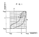
- In general, various highly efficient coding systems is using the fact that voice information is locally existent within the range in which parameters are available. The above technical idea has been further developed positively. Combination of a plurality of parameters is represented with a vector. The localization of the vectors is noticed, so that the voice informations can be represented by smaller informations. Such a system, called a vector quantization system and disclosed in, for example, R.M. Gray, "Vector Quantization" IEEE ASSP Magazine, pp. 4-29, (1984, 4) has been highlighted. To describe the vector quantization system more specifically, when a voice is expressed using suitable parameters, the parameters are distributed in a special pattern because of the structure of human mouth. As an example, Fig. 1 graphically shows a voice expressed in terms of two parameters a and b. Most of human speech can be expressed by parameter values filling within an area A. In order for the voice to undergo vector quantization, the area A is divided into a great number of domains and
codes - In the case of scaler quantization, when the voice represented by a point x in Fig. 1 is coded, a₁ as a parameter "a" and b₁ as a parameter "b" are independently transmitted. On the other hand, in the case of vector quantization,
code 12 is transmitted. Thecode 12 specifies the divided region in which the point x is included. - In the case of scalar quantization, the voice information is represented with the value from amin to amax as the parameter "a" and with the value from bmin to bmax as the parameter "b" in order to cover the whole area in which there is voice information. Since the parameters "a" and "b" are independently used, the information used for representing the voice is allotted to each divided region within the rectangular region represented by B in Fig. 1. As a result, the voice information is allotted to the region (B - A), even though the voice is not actually present in that region. On the other hand, in the case of vector quantization, since the information used for representing the voice is allotted only in the region represented by A in Fig. 1 in which the voice is present, the information can be compressed more than is possible with scalar quantization.
- The method of decoding transmitted codes in the vector quantization is explained below. Each divided region is represented by a representing vector, each having values for each of the parameters which represent the divided region. The representing vector is called a code vector or a centroid. this system is provided with a table called a code book in which the representing vector and the corresponding code are listed. Identical code books are provided on the transmitting side (coding side) and on the receiving side (decoding side) respectively, so that the representing vector corresponding to the transmitted code can be obtained by searching the code book. However, in general, there is a difference between the vector representing the actual input voice (referred to hereinafter input vector) and the representing vector which is obtained. The difference is a quantization distortion.
- In the vector quantization system, in order to realize high quality voice coding, it is necessary to prepare in advance a code book of high quality which can express a voice with as high fidelity as possible. To this end, many problems have to be solved including the necessity of use of a sufficiently large amount of speech as training data and the decision as to how many codes the code book should contain and as to what parameters should be used. As a countermeasure against problems encountered in preparation of the code book, a fuzzy vector method (for example, H.P. Tseng, et al, "Fuzzy Vector Quantization Applied to Hidden Markou Modeling" ICASSP 87′, 4 (1987)) has been proposed wherein a membership function is used for determining the input voice through interpolation. The membership function represent the degree of similarity between the input vector and each of the representing vectors by using numerical values. The similarity is concretely represented by the distance between the input vector and each of the representing vectors. In the fuzzy vector method, in spite of the fact that the voice quality is expected to be improved in proportion to the quality of the code book, it is not used as technique for transmission because of a large amount of the membership function. At present, the use of the fuzzy vector method for pre-processing of speech recognition has been studied at the most. In addition, a KNN method (for example, "Study of Normalization of Spectrogram by Using Fuzzy Vector Quantization" by Nakamura et al., Papers SP87-123 of Voice Research Conference, Feb. 19, 1988) has been proposed wherein with the view of decreasing the amount of information, the input voice is compared with each of all the representing vectors registered in a code book so that only N vectors close to a point representative of the input vector may be used. The KNN method, however, requires a sorting processing for selection of the N representing vectors (code vectors) close to the input voice point and the amount of processing in the sorting processing raises a very severe problem from the practical standpoint. Further, the transmission of codes of all the N representing vectors causes loss on the amount of the information to be transmitted.
- An object of the present invention is to provide method and apparatus which can reproduce an input voice with fidelity by using a smaller amount of transmission information in voice coding based on vector quantization.
- A second object of the invention is to provide method and apparatus which are suitable for reproduction of a high-quality decoded voice and vector quantization.
- According to the present invention, to accomplish the first object, first to fourth methods may be employed.
- In accordance with the first method, N codes of neighboring vectors are registered in association with individual codes in the code book.
- In accordance with the second method, fuzzy vector quantization is effected by selectively using representative vectors (hereinafter referred to as code vectors) in the code book in accordance with an input vector. Means for selecting the code vectors includes means for selecting candidates for the code vectors to be used, means for evaluating the relation of the candidate vectors to the input vector, and means for determining a vector to be used on the basis of results of the evaluation.
- In accordance with the third method, results of the immediately preceding quantization (reconstructed vectors) are used to approximate the succeeding input vector. Since the reconstructed vector is used for quantization of the input vector, the coding station has inverse quantization means having the same function as that of inverse quantization means provided in the decoding station, storage or memory means for holding the reconstructed vector until a quantization processing of the succeeding input vector starts, and means for reading the reconstructed vector upon quantization.
- In accordance with the fourth method, means is employed which approximates an input vector by using a function of a plurality of representative vectors (code vectors) in the code book. The function approximation means includes means for selecting a plurality of code vectors on the basis of a predetermined evaluation criterion, and means for calculating parameters of the function.
- According to the invention, to accomplish the second object, Fourier expansion of the spectral envelope is employed. For example, used as elements of vector are parameters called power spectrum envelope (PSE) parameters or quasi stationary spectrum (QSS) parameters. The PSE parameters are described in a paper entitled "Method of Analyzing Voice Power Spectral Envelope Based on Sampling at Intervals of Fundamental Frequency" by nakajima et al, Papers SP 86-94 of Voice Research Conference, Denshi-jyohhoh Tsuhshin Gakkai, 1986 and the QSS parameters are described in Japanese Patent Application No. 63-166714. According to these literatures, in the coding station, a voice is subjected to Fourier transform in a predetermined relationship with a pitch period equal to a vibration period of the vocal chords, and only harmonics (line spectrum components) of the pitch frequency are extracted. The harmonics are squared to obtain a power spectrum and the envelope of the power spectrum is expanded in terms of a cosine series and coefficient values of the cosine series are used as element values (parameters) of vector. In the decoding station, element values of vector are read out of the code book and subjected to inverse transform to obtain a cosine series value, and envelope of the spectrum is determined and subjected to Fourier inverse transform to recover waveforms which in turn are superimposed sequentially at the pitch period to reproduce a voice waveform.
- Advantageously, according to the invention, the amount of the information can always be reduced as compared to that by the conventional fuzzy vector quantization and hence a high-quality voice can be transmitted using the same amount of information. Conversely, for the same quality, the amount of information can be reduced as compared to the conventional method.
-
- Fig. 1 is a graphic representation useful to explain the principle of vector quantization.
- Fig. 2 is a block diagram illustrating the construction of a system according to the invention.
- Fig. 3 is a block diagram of an analyzer in the Fig. 2 system.
- Fig. 4 is a diagram for explaining the operation of the analyzer.
- Fig. 5 is a block diagram of a fuzzy vector quantizer in the Fig. 2 system and based on the first method of the invention.
- Figs. 6 and 7 are diagrams useful to explain the operation of the Fig. 5 fuzzy vector quantitizer.
- Fig. 8 is a block diagram of a fuzzy vector inverse quantizer in the Fig. 2 system.
- Fig. 9 is a block diagram of a synthesizer in the Fig. 2 system and used for reconstruction of an input voice signal.
- Fig. 10 is a diagram for explaining the operation of the synthesizer.
- Fig. 11 is a graph showing the effect of the first method of the invention.
- Figs. 12A and 12B show a modification based on the first method.
- Fig. 13 is a block diagram of a fuzzy vector quantizer based on the second method of the invention.
- Fig. 14 is a diagram useful in explaining the manner of determining a reconstructed vector.
- Figs. 15 and 16 are graphs for explaining the effect of the second method of the invention.
- Fig. 17 is a block diagram of a fuzzy vector quantizer based on the third method of the invention.
- Fig. 18 is a block diagram of a fuzzy vector inverse quantizer based on the third method of the invention.
- Fig. 19 is a block diagram of a fuzzy vector quantizer based on the fourth method of the invention.
- Fig. 20 is a diagram for explaining the manner of determining a synthesis vector based on the fourth method.
- Fig. 21 is a graph showing the effect of the fourth method of the invention.
- The first method of the present invention will be implemented as below.
- When a voice desired to be transmitted is applied to the system, the voice is converted into the vector (input vector) representing the features of the voice inputted. Then it is compared sequentially with individual code vectors in a code book and one code nearest to the input voice is selected. Since N codes neighboring the selected code are registered as neighboring codes, code vectors corresponding to the N codes and the initially selected code are taken out, membership function is determined from the distance between the input vector and each vector, and the initially selected code and N+1 membership functions are coded into a single transmission code which in turn is transmitted. In the receiving station, there is provided a code book having the same information as that of the code book in the transmitting station, and code vectors corresponding to the received code and N code vectors corresponding to the N registered codes are read out of the code book and combined with membership functions to reconstruct the voice. N code vectors are identical with the N code vectors selected in the transmitting station. As is clear from the above, since the transmission is perfected with only one transmission code, the transmitting station is not required to select N+1 codes and the amount of information necessary for transmission of N codes is unneeded, coding allotment in transmission can be eliminated to ensure highly efficient transmission.
- A pitch period equal to a vibration period of the vocal chords is extracted from the input voice, and the input voice is subjected to a Fourier transform at a constant interval or a interval which has a predetermined relationship to the pitch period and thereafter converted into a power spectrum. Only information about harmonic positions of the pitch period of the power spectrum is taken out, and a series of the information is normalized so as not to be affected by the magnitude of voice and thereafter subjected to cosine expansion. Coefficients of the orders extending up to, for example, about 20-th order are than taken out. The coefficients are obtained from cosine transform in which the series of the information is normalized by a half frequency width of a sampling frequency. Therefore, substantially the same coefficients can be obtained from a spectrum of a voice of a different pitch period which is uttered from the same vocal tract. Accordingly, by using the coefficients as elements of vector, the inter-vector distance can be made to be smaller for voices having similar spectral envelopes and the vector quantization can be done very conveniently. In the cosine expansion, components of lower order of vector indicate global characteristics of spectrum and components of higher order provide information indicative of fine characteristics of spectrum and therefore the code book can be prepared systematically to permit the speed of reconstruction to be increased very conveniently by using tree coding technique. For transmission, level information for recovering the vector information, pitch period information and voice magnitude may be used.
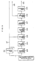
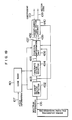
- An embodiment of the first method according to the invention will now be described by making reference to the accompanying drawings. Fig. 2 is a block diagram useful to explain the embodiment and in this block diagram, only unidirectional flow of signals throughout transmitting and receiving stations is illustrated with omission of communication lines in the inverse direction for avoidance of prolixity of illustration.
- Referring to Fig. 2, an input voice 101 is applied to a
buffer memory 103 of a bifacial structure via an analog/digital (A/D)converter 102. Thememory 103 is adapted to adjust timings for the succeeding processings and to prevent interruption of the input voice. Ananalyzer 104 extracts, from the voice sent from thebuffer memory 103,pitch information 107,spectrum information 106 andlevel information 105. In this embodiment,spectrum information 106 obtained in theanalyzer 104 is represented by vector. Afuzzy vector quantizer 108, one of features of the present invention, receives thespectrum information 106 to produce anearest vector code 109 and amembership function 110 indicative of the similarity between input vector and code vector. Thevector code 109,membership function 110,pitch information 107 andlevel information 105 are sent to areceiver 113 via transmitter 111 and transmission line 112. In the receiving station, the receiver delivers avector code 109′, amembership function 110′,pitch information 107′ andlevel information 105′ to a fuzzy vectorinverse quantizer 114 and theinverse quantizer 114 reconstructs spectrum information which is fed, along with thepitch information 107′ andvector information 105′, to a synthesizer 116. A voice waveform reconstructed at the synthesizer 116 is fed via an outputbifacial buffer memory 117 to a D/A converter 118 from which anoutput voice 119 is reproduced. - To detail the blocks of Fig. 2, reference should first be made to Figs. 3 and 4 which are useful to explain the
analyzer 104. - In this embodiment, the analyzer is based on the power spectral envelope (PSE) analysis method. The PSE analysis method is detailed in a article entitled "Voice Analysis and Synthesis System Based on Power Spectral Envelope (PSE)" by Nakajima et al, Transactions of Acoustical Society of Japan, Vol. 44, No. 11 (1988, 11) and will be outlined herein.
- Referring to Fig. 3, a
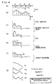
pitch extractor 201 extracts pitch information from the input voice. A variety of methods for extraction of pitch information known and used widely may be applicable to the preset invention and will not be described herein. Awaveform windowing unit 203 is adapted to window a waveform interval of the input voice which is necessary for analysis of the spectrum information and in the so-called PSE method, a waveform portion of an interval T₀ containing about three pitch periods is windowed as shown at (a) in Fig. 4. However, in the guasi stationary spectrum (QSS) method, an interval equalling one pitch period T′₀ may be windowed. Windowing can be done easily by detecting maximum values of waveform while consulting the pitch information. The windowed waveform portion is sent to aFourier transform unit 204 and transformed into a Fourier series. In the PSE method, it is efficient to use a fast Fourier transform (FFT) wherein a commonly used window function such as hamming window or Gauss window is applied and then as many as approximately 2048 points are used which are obtained by filling zero data forwardly and backwardly of the window. In the QSS method, however, the application of window function is not effected and the number of points may be as small as about 512 because, as will be described later, sampling of harmonics of the pitch frequency is not effected and hence transform using such many pieces of data as amounting to 2048 points is not always required. As a result of the FFT, a Fourier series as shown at (b) in fig. 4 is obtained. The resulting Fourier series is of a line spectrum structure corresponding to harmonics of the pitch frequency in the PSE method, but in the QSS method no line exists and the resulting Fourier series is a continuous spectrum. - A
pitch re-sampling unit 205 is needed for the PSE method but unneeded for the QSS method. Thepitch re-sampling unit 205 extracts only a harmonic component (line spectrum component) of the pitch frequency as shown at (c) in Fig. 4 from the spectrum information as shown at (b) in Fig. 4 resulting from the FFT. For simplicity of consideration under varying frequency, in the PSE method, the thus extracted data shown at (c) in Fig. 4 is normalized with respect to unit π of the period of the cosine expansion to be described later and in the QSS method, the half fs/2 of sampling frequency of the original spectrum shown at (b) in Fig. 4 is normalized with respect to angular frequency π. - To ensure evaluation in terms of energy, a power
spectral operation unit 206 squares each component of the spectrum and converts it into a power spectrum as shown at (d) in Fig. 4. Alogarithmic operation unit 207 applies logarithmic operation to each component to provide a logarithmic power spectrum as shown at (e) in Fig. 4. Obviously, the above two operations can be unified to obtain a value equal to a doubled logarithm of absolute value. Alevel normalization unit 208 is operative to absorb level variations in the input voice so as to provide a signal which does not depend on the level of the input voice. In an alternative, the level normalization may be unified into the sixth-order term of cosine expansion and may be delivered as 0-order term output from a cosine converter 209 to be described below. The cosine converter 209 produces coefficients of cosine expansion of the envelope of the logarithmically operated power spectrum which are indicated in
Y = A₀ + A₁cosλ + A₂cos2λ + A₃cos3λ + ..... (1)
where Y represents the envelope. Since the cosine function is an orthogonal function, A can be obtained through multiplication of the envelope Y and cos(nX. Thus, A₀ is delivered aslevel information 105, and A₁, ---, Am are delivered asspectrum information 106. - In a voice having a low pitch frequency, the number of pitch harmonics which fall within a predetermined band is large and the number of pieces of effective information increases correspondingly, thereby enfuring that the available value of the order m of spectrum information can be extended to a high value. Therefore, by making the value of m variable depending on the pitch and preparing a code book containing vectors of different orders which stand for spectral parameters, the information can be utilized efficiently.
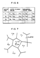
- Turning to Figs. 5, 6 and 7, the fuzzy vector quantizer will be described. The quantizer constructed as shown in Fig. 5 includes a
code book 401 for recording data as shown in Fig. 6. To minimize the speed of retrieving the code book, the search range of individual pieces of spectrum information may be limited. Also, the pitch information may be utilized to determine the upper limit of the order of spectrum information and distance calculation to be described below may be carried out under the condition of the thus determined upper limit. The construction of thecode book 401 is explained below. In the code book, a code Vi allotted to the code vector vi and the corresponding elements {Ai1, Ai2, ---, Aim} of the code vector vi are listed. In the present invention, codes Vi1, Vi2, --- ViN corresponding to neighboring vectors ki1, ki2, ---, kiN of the code vector vi are also listed as shown in Fig. 6. Anearest vector detector 402 calculates a distance dik between a input vector xk (k represents an order of the input vector which is inputted. It is independent of the neighboring vectors (ki1, ki2, ---, kiN) and each code vector vi recorded on thecode book 401 and selects anearest vector code 403 which is particularly calledVi 403 herein. With thevector code Vi 403 determined, neighboring vectors Ki1, ---, KiN corresponding to the codes Vi1, Vi2, ---, ViN are determined, because the codes Vi1, Vi2, ---, ViN are resistered in the code book as shown in Fig. 6. N measures 5 to 6. The vector information xk, code vector vi and neighboring vectors Ki1, ---, KiN are diagrammatically illustrated in Fig. 7. The input vector xk lies within a domain of the code vector vi and domains of the neighboring vectors Ki1, ---, KiN surround the code vector domain. In the example of Fig. 7, a vector nearest to the input vector xk is the code vector vi. - In fuzzy vector quantization, the input vector is expressed by the similarity between the input vector and each of a plurality of code vectors, and the degree of similarity is expressed in numerical form by using membership function. The membership function is relatively determined from the distance between the input vector and each of code vectors. The fuzzy vector quantization is detailed in a literature entitled Normalization of Spectrogram Using Fuzzy Vector Quantization" by Nakamura et al, Transactions of Acoustical Society of Japan, Vol. 45, No. 2, 1989 and in a literature quoted therein. The case of fuzzy vector quantization of the input vector xk by using the nearest code vector vi and the neighboring code vectors Ki1, ki2, ---, KiN of the vector vi is explained below. The nearest vector vi is represented as Ki0 in order to bring a uniformity in the code. Given that the input vector xk is distant from the code vector vi and from each of the code vectors kiℓ (ℓ=0, 1, 2, ---, N) by dℓk. Then, the distance
dℓk = || xk - Kiℓ || (2)
, where symbol "|| ||" represents weighted Euclid distance and ℓ = 0, 1, ---, N is calculated at aunit 404 for calculating the distance from code vectors. The thus calculated distance dℓk (405) is sent to a membershipfunction calculation unit 406. - When the input vector does not coincide with any code vectors, membership functions µℓk for individual code vectors are given by

- If the code vector coincides with any one of the code vectors, the membership function for the coincident code vector has a value of 1 (one) and membership functions for the remaining code vectors are rendered 0 (zero). In other words, for dℓk = 0, µℓk = 1.
- In this manner, N+1 membership functions µℓk and
code Vi 403 of the code vector vi are delivered assignals - Processings in the receiving station will now be described.
- Fig. 8 is a diagram for explaining the fuzzy vector
inverse quantizer 114. When theinverse quantizer 114 receives acode 109′ of the code vector, thecode vector vi 403 equal to Ki0 and the neighboring vectors Ki1, ---, KiN are taken out of acode book 701 which is identical with thecode book 401 in the transmitting side, and sent to avector reconstruction unit 702. Thevector reconstruction unit 702 also receives membership functions µℓk 110′ and it uses the vectors Ki1, ---, KiN and membership functions µℓk 110′ to produce a reconstructed vector x′k of the input voice signal which is
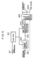
vector information 115 to the synthesizer 116. - The synthesizer 116 will now be described in greater detail with reference to Figs. 9 and 10. In Fig. 9, a logarithmic power
spectrum reconstruction unit 801 uses the transmitted level information A₀′ 105′ and elements A₁′, A₂′, ---, Am′ of the reconstructedvector information 115 to produce a logarithmic power spectrum envelope Y′ 802 which is
Y′=A₀′+A₁′cosλ+A₂′cos2λ+ ... +Am′cosmλ (5)
wherein
0 ≦ λ ≦ π
Thus, the element values as shown at (a) in Fig. 10 are synthesized pursuant to equation (5) to provide a logarithmic power spectrum as shown at (b) in Fig. 10. - At an inverse
logarithmic converter 803, the reconstructed logarithmic power spectrum Y′envelope 802 is subjected to (1/2)log⁻¹ conversion andamplitude spectrum envelope 804 represented with linear scale is obtained from theconverter 803 as shown at (c) in Fig. 10. Thespectrum 804 is sent to an inverseFourier transform unit 805. Thespectrum 804 undergoes inverse fast Fourier transform (IFFT) at the inverseFourier transform unit 805 to produce avoice signal 806 as shown at (d) in Fig. 10. Thevoice signal 806 is obtained as a symmetric impulse response under the condition of zero-phasing operation so as not to generate a distortion on the waveform in a following waveform synthesizing stage. At awaveform synthesis unit 807, thevoice signal 806 is sequentially shifted by the pitch interval in accordance with thepitch information 107′ so as to be added together and the thus synthesized signal is delivered out of theunit 807, as shown at (e) in Fig. 10, asvoice waveform 808. For edition and synthesis of voice signal at the pitch period, a widely known method may be used and will not be detailed herein. The processings in the receiving station do not differ for the PSE method and the QSS method. - By introducing a fixed interval of about 10 milliseconds to 20 milliseconds between fundamental processings in the transmitting and receiving stations, the signal during the fixed interval may be interpolated with estimation spectrum information A₀′, A₁′, ---, AN′ for estimation during reconstruction, thereby ensuring compression of the amount of information.
- In order to further improve accuracy of transmission, a fuzzy vector inverse quantizer may be provided in the transmitting station to perform a processing corresponding to equation (4), the difference between input vector xk and reconstructed vector x′k may then be evaluated and thereafter membership function values may slightly be modified sequentially to reduce the transmission error, beginning with a membership function having a large value, in consideration of the fact that the membership function for a small distance between input voice vector and code vector has a large value.
- Obviously, the fuzzy vector quantization may be omitted and only vector quantization may be applied to the PSE method or the QSS method. This modification may be practiced easily by removing the component associated with fuzzy vector quantization from the construction of Fig. 2.
- One problem of the vector quantization is that the amount of processings necessary for determining the distance between each vector on the code book and the input vector increases. In accordance with the invention, the amount of processings can be decreased greatly by taking advantage of characteristics of the spectrum information. More particularly, pieces of spectrum information A₁, ---, Am sequentially reflect characteristics of spectra, beginning with global characteristics and extending to fine characteristics, and a vector and a vector similar thereto have similarity in spectrum information of lower order. Accordingly, if code vector of spectrum information of lower order having similarity are grouped on the code book and pieces of spectrum information of higher order are sequentially taken out of the code book in accordance with a hierarchy, vectors of lower order can first be checked sequentially for their distances from the input vector and then only resembling vectors can be examined in terms of spectrum information of higher order, thereby ensuring that resembling codes can be detected without being compared with all of the codes. Further, evaluation can be done depending on the order by, for example, weighting more heavily lower orders which greatly affect voice quality.
- Obviously, the coding method described herein may be used for not only transmission but also storage of, for example, voice mail, and the analyzer may be used as an independent analyzer dedicated to voice recognition and the synthesizer as an independent voice synthesizer.
- Meritorious effect of the first method according to the invention is graphically shown in Fig. 11, demonstrating that for the same quantization distortion, the number of transmission bits can be reduced greatly as compared to the prior art method.
- Referring now to Figs. 12A and 12B, a modification based on the first method of the invention will be described wherein in parallel with the quantization based on the first method, the quantization distortion is further quantized in accordance with the first method.
- In one circuit shown in Fig. 12A, quantization based on the first method is effected at the
fuzzy vector quantizer 108 and results of the quantization are delivered as code and membership function. Then, a fuzzy vectorinverse quantizer 114 produces a reconstructed vector S₁′ of the input voice vector S₀ and the quantization distortion is obtained aserror 1. - In the other circuit shown in Fig. 12B, two kinds of code books are employed. An
ordinary vector quantizer 151 uses a first code book in order to perform vector quantization on the basis of neighboring vectors of an input voice vector S and a resulting code is delivered as first code. Then, a vectorinverse quantizer 152 produces a reconstructed vector S′ and asubractor 153 produces a quantization error of e = S₀- S₂′. Afuzzy vector quantizer 154 responsive to the quantization error e uses a second code book to perform fuzzy vector quantization based on the first method and resulting second code and membership function are delivered out of thequantizer 154. A fuzzy vectorinverse quantizer 155 produces a reconstructed vector e′ of the quantization distortion e. Avector inverse quantizer 156 also operates to produce a reconstructed vector S′ from the first code and the reconstructed vector S′ is added with the reconstructed vector e′ at anadder 157 to produce a new approximation vector S˝ of the input voice vector S. The difference between S˝ and S₀ is calculated at asubractor 158 and delivered therefrom aserror 2. Thus, in this modification, theerrors errors - The second method of the invention will now be described.
- According to the second method, fuzzy vector quantization is effected by selectively using code vectors in a code book in accordance with an input vector and the second method is implemented as follows.
- When receiving a voice which is desired to be transmitted, an analyzer extracts a characteristic vector from the voice. The characteristic vector is sequentially compared with code vectors in the code book and a code vector by which the quantization distortion can be minimized is selected. In case where the invention is applied to the conventional fuzzy vector quantization, a predetermined number of code vectors which are close to the input vector in an orderly manner are exemplarily selected as candidate vectors. In case where the first method by which vectors neighboring individual code vectors are registered in advance is applied, the neighboring vectors are graded in accordance with closeness to the input vector and used as candidate vectors.
- An embodiment of the second method is implemented with the same system construction as that illustrated in Fig. 2.
- In particular, a fuzzy vector quantizer having vector selection function is used in this embodiment and it is illustrated in Fig. 13. Referring to Fig. 13, values of elements of code vectors and their codes are stored in a
code book 401. - When the
input vector 106 is applied to anearest vector detector 402, individual code vectors are read out of thecode book 401 and the distance between each code vector and theinput vector 106 is calculated at thedetector 402 and delivered therefrom asdistance value 403. The scale of the distance is set up in terms of Euclid distance in which elements of vector are weighted but obviously other suitable type of scale may also be used. In addition, the range of code vectors subjected to distance calculation may be limited by using, for example, thepitch information 107. - A
candidate vector selector 414 selects candidates of code vectors for vector evaluation to be described below. Thevector selector 414 looks up the distance values 403 to select a predetermined number (c) of vectors having smaller distances and deliverscodes 415 of candidate vectors which are aligned orderly in accordance with closeness to the input vector. Alternatively, candidate vectors may be selected in accordance with other selection criterion than the above which prescribes a predetermined uppermost threshold of distance value for selection or both a predetermined uppermost number and a predetermined uppermost threshold of distance value for selection. If all of the code vectors in the code book are subjected to distance calculation, the candidate vector selector is not required. - A
vector selector 416 calculates and evaluates quantization distortions in respect of the candidate vectors in accordance with the following procedure. - Since the minimum value dmin of the
value 403 of distance from the input vector equals the quantization distortion resulting from the vector quantization of the input vector using the nearest vector (so-called ordinary vector quantization), the minimum value is first used as criterion of evaluation. Subsequently, candidate vectors other than the nearest vector and combined with the nearest vector one by one to perform fuzzy vector quantization and calculate quantization distortions. When the minimum value of the quantization distortions is below dmin, a candidate vector having that minimum value is selected. Thus, the minimum value is updated to the last mentioned minimum value which is also designated by dmin. Subsequently, in addition to the nearest vector and the vector selected as above, the remaining candidate vectors are subjected to the above procedure sequentially one by one and added until the number of the remaining candidate is zeroed. The above procedure is effective for an application where candidate vectors having minimized quantization distortions are all selected. In an alternative, the procedure may be stopped when the number of selected vectors reaches a predetermined value. - A simplified method of selecting the code vectors may be employed wherein vectors are added orderly in accordance with the closeness to the input vector and if quantization distortion after the addition is smaller than that before the addition, a vector now added is selected.
- In this embodiment, the quantization distortion is used as evaluation criterion. Alternatively, when the inverse quantizer is provided in the transmitting station as in the modification based on the first method, a vector can be selected which minimizes the quantization distortion by using the difference between input vector and reconstructed vector as evaluation criterion. In another alternative, vector selection may be carried out by taking advantage of the positional relation in the vector space Fig. 14 is for explaining the concept of this alternative. for simplicity of explanation, it is assumed that vectors are two-dimensional vectors. In Fig. 14, xk represents an input vector and v1 the nearest vector. Given that a vector vi is to be evaluated, a reconstructed vector xk′ resulting from fuzzy vector quantization using v1 and vi lies on a straight line connecting v1 and vi. Accordingly, the condition for the distance between xk′ and xk being smaller than that between v1 and xk is that vi is closer to xk than to a tangent at v1 on a circle centered at xk and having a radius of dmin. In other words, when the distance between xk and v1 and that between xk and vi are known, a vector minimizing quantization distortion can be decided by using the magnitude of angles of the three vectors v1, xk and vi.
- Specifically, the reconstructed vector xk′ is determined through interpolation using the vectors vi and v1 which satisfy ϑc < ϑ₁ in Fig. 14.
- A
fuzzy vector quantizer 408 shown in Fig. 13 looks up avector code 417 delivered out of thevector selector 416 and uses the selected vector to perform fuzzy vector quantization of the input vector. More specifically, membership functions are calculated pursuant to equation (3) described previously. Thequantizer 408 delivers selectedvector code 109 and membership functions 110. If the number of vectors to be selected is variable, information about the number of vectors is delivered. Since the sum of membership function values is 1 (one) by nature and the last membership function value is known from (1_ the sum of previously delivered values), delivery of membership functions which are smaller in number b one than the vectors suffices. If the number of actually selected vectors does not reach a predetermined (fixed) value, values of membership functions for the residual number of vectors can be zero. - When the second method is applied to the first method, the candidate vectors are the nearest vector and vectors neighboring the nearest vector and registered in advance.
- In this case, the function of the
candidate vector selector 414 is simplified considerably. Also, the vector code delivered out of the final stage offuzzy vector quantizer 408 is the nearest vector code alone. Non-selected ones of the candidate vectors can be identified by making associated membership function values zero. The receiver is the same for the fist and second methods. - Meritorious effects of this embodiment are graphically illustrated in Figs. 15 and 16. In these figures, the quantization distortion is plotted relative to the size of the code book for the case where the vector selection function of the invention is applied and the case where the vector selection function is not applied. In particular, Fig. 15 shows an example where the vector selection function is applied to the ordinary fuzzy vector quantization and Fig. 16 shows an example where the vector selection function is applied to the fuzzy vector quantization based on the first method in which the code book is registered in advance with neighboring vectors.
- Comparison at the same code book size clearly shows that the quantization distortion is suppressed in the present embodiment.
- The third method of the invention will now be described. In the third method, the nature that characteristics of the voice signal change with time relatively gradually is utilized and by using results of the immediately preceding quantization (reconstructed vector), quantization of the succeeding input vector is effected.
- The third method is implemented as follows. When a voice desired to be transmitted is received, the voice is divided into frames at predetermined intervals and a characteristic vector is extracted from each frame at the analyzer. The characteristic code (input vector) is compared with code vectors in the code book. Then, a predetermined number of code vectors which are graded in accordance with the closeness to the input coded are selected. For the first method wherein neighboring vectors are registered in advance for individual code vectors, the registered neighboring vectors are read out. At the same time, a reconstructed vector resulting from inverse quantization of an input vector which has undergone vector quantization in the preceding frame is read out.
- Quantization distortion and the like of code vectors read out of the code book and reconstructed vectors are evaluated in accordance with a predetermined evaluation criterion to select vectors to be used. By using codes of these vectors and membership functions representative of the degree of similarity between the input vector and each code of these vectors, the input vector is quantized. The codes and membership functions are transmitted to the receiving station and at the same time applied to the inverse quantizer in the transmitting station at which inverse quantization is effected using the code vector and reconstructed vector used for quantization of the input vector to produce a reconstructed vector which in turn is stored in a reconstructed vector memory to be described later.
- As is clear from the foregoing, the use of the reconstructed vector in the preceding frame for the fuzzy vector quantization attains the same effect as that attained by the addition of a code vector having high similarity to the input vector and therefore the vector quantization with reduced quantization distortion can be accomplished without increasing the amount of information,.
- Referring to Fig. 17, the fuzzy vector quantizer utilizing the reconstructed vector will be described.
- When receiving the
input vector 106 of a voice, anearest vector detector 402 reads areconstructed vector 421′ in the preceding frame from a reconstructedvector memory 419 and individual code vectors from acode book 401 and calculates distances of the code vectors from theinput vector 106 to deliver adistance value 403. The scale of the distance is set up in terms of Euclid distance in which elements of vector are weighted but other suitable types of scale may also be used. In addition, the range of code vectors subjected to distance calculation may be limited by using, for example, thepitch information 107. - A
candidate vector selector 414 selects candidates of code vectors for vector evaluation to be described below - The
vector selector 414 looks up thedistance value 403 to select a predetermined number (c) of vectors having smaller distances s deliverscodes 415 of candidate vectors which are aligned orderly in accordance with the closeness to the input vector. If thereconstructed vector 421′ is contained in the candidate vectors, a code of other value than that assigned to the code vectors, for example, zero is assigned to the reconstructed vector. Candidate vectors may be selected in accordance with other selection criterion than the above which prescribes a predetermined uppermost threshold of distance value or both a predetermined uppermost number and a predetermined uppermost threshold of distance value for selection. If all of the code vectors in the code book are subjected to distance calculation, the candidate vector selector can be omitted. - Since the reconstructed vector in the preceding frame is selected as candidate vector in many applications, the reconstructed vector may constantly be treated as candidate vector. Further, by treating, as candidate vectors, only one of the code vectors in the code book which has the highest similarity to the input vector and a reconstructed vector, the function of the candidate vector selector can be simplified considerably.
- A
vector selector 416 calculates and evaluates quantization distortions in respect of the candidate vectors in accordance with the same procedure as described for the second method. - A
fuzzy vector quantizer 408 looks up avector code 417 delivered out of thevector selector 416 and uses the selected vector to perform fuzzy vector quantization of the input vector. - The fuzzy vector quantizer delivers
vector code 109 andmembership function 110 which are sent to the transmitter 111 and to aninverse quantizer 420. Using the same code vector andreconstructed vector 421′ as those used for quantization of theinput vector 106, theinverse quantizer 420 calculates a reconstructedvector 421 for theinput vector 106. Specifically, the reconstructed vector xk′ 421 is calculated pursuant to equation (4) described previously. The reconstructedvector 421 is transferred to the reconstructedvector memory 419 and stored therein. Concurrently therewith, the reconstructed vector in the preceding frame is erased. Obviously, the updated reconstructed vector is identical to a reconstructed vector produced in the receiving station. - In the foregoing, the vector selection function of the present embodiment is described as applied to the conventionally proposed, ordinary fuzzy vector quantization. On the other hand, the vector selection function may also be applied to the fuzzy vector quantization based on the first method wherein vectors neighboring each code vector are registered in advance.
- In this case, the candidate vectors are the nearest vector, vectors neighboring the nearest vector and registered in advance, and
reconstructed vector 421′. Accordingly, the function of thecandidate vector selector 414 is simplified considerably. Also, the vector code delivered out of the final stage offuzzy vector quantizer 408 is the nearest vector code alone. Non-selected ones of the candidate vectors can be identified by making associated membership function values zero. - The receiving station will now be described.
- Fig. 18 is for explaining the fuzzy
vector universe quantizer 114. When avector code 109′ is received by acode book 701, the corresponding code vector vi is read out of thecode book 701 and at the same time the reconstructedvector 704 in the preceding frame is read out of a reconstructedvector memory 703. Avector reconstruction unit 702 responds to the read-out code vector and reconstructed vector and received membership functions µℓk 110′ to reconstruct a vector pursuant to equation (4) described previously. Thecode book 701 in the receiving station has the same contents as that of thecode book 401 in the transmitting station. Also, the reconstructedvector 704 is identical to the reconstructedvector 421′ in the preceding frame in the transmitting station. The reconstructed vector
xk′ = {A₁′, A₂′ ....., Am′}
is delivered asspectrum information 115 to the synthesizer 116. - In accordance with this embodiment, the quantization distortion can be reduced at a portion where a series of similar spectra exists, especially, at a vowel portion and a smooth, reproduced voice can be obtained. In addition, since the vector used for fuzzy vector quantization is selected, sharpness of the reproduced voice can be maintained even when the nature of the spectrum changes remarkably as in the case of the change of constant to vowel and hence a reproduced voice of high articulation can be obtained.
- In a modification, two kinds of code books may be employed. More particularly, a first code book is used for the ordinary vector quantization in which a code vector merely close to an input vector is made to correspond to the input vector, and a second code book is dedicated to quantization distortion. The second code book may be used in the following manner. More particularly, when the input vector is subjected to the ordinary vector quantization by using the first code book, quantization distortions are produced which in turn are subjected to fuzzy vector quantization by using the second code book containing vectors representative of quantization distortions in parameter form. A first quantization distortion obtained after completion of the above two steps of vector quantization is compared with a second quantization distortion obtained through the fuzzy vector quantization. Thus, the quantization scheme which provides smaller one of the first and second quantization distortions is selected. For an input vector for which the quantization distortion can not be reduced efficiently through fuzzy vector quantization, the second code book dedicated to quantization distortion can be used effectively to improve quantization characteristics.
- The fourth method of the invention will now be described.
- The fourth method uses, in addition to the ordinary vector quantization means (code book, means for comparing the input vector with code vectors and means for selecting the nearest code vector), means for approximating the input vector by using a function of a plurality of code vectors in the code book. The function approximation means includes means for selecting a plurality of code vectors in accordance with a predetermined evaluation criterion, and means for calculating parameters of a function.
- the fourth method is implemented as follows. When receiving a voice described to be transmitted, an analyzer extracts a characteristic vector from the voice. The characteristic vector is sequentially compared with code vectors in the code book to select the nearest vector. At that time, the distance between input vector and code vector corresponds to quantization distortion in the ordinary vector quantization.
- Subsequently, code vectors to be combined with the nearest vector are selected. Candidates for combination vectors are registered in advance in respect of individual code vectors (usually, vectors neighboring the nearest vector). More specifically, candidate code vectors registered for the nearest vector are sequentially taken out and combined with the nearest vector to provide a linear combination which approximates the input vector. In this procedure, the coefficient of the linear combination is determined in such a manner that the highest degree of approximation can be obtained. Approximation errors (corresponding to quantization distortions) are calculated in respect of individual candidate vectors and a candidate vector having the minimum error is selected.
- The coefficient of a linear combination of the nearest vector and codes of selected code vectors stands for transmission parameter. In the receiving station, the input vector is reconstructed (inverse-quantized) from the above information in the form of a linear combination of designated code vectors.
- While the amount of information (the number of bits) indicative of the code of the nearest vector must amount to the number of bits corresponding to the size of the code book, the number of bits of codes of the combination code vectors which amounts to the number of bits corresponding to the number of registered candidate vectors sufficies. Individual coefficients of the linear combination are subjected to scalar quantization for the purpose of transmission but the number of combination code vectors usually amounting to only one sufficies. Accordingly, in accordance with the present embodiment, there is no need of transmitting the surplus amount of information and the information can be compressed greatly as compared to the prior art method.
- Fig. 19 is for explaining the fourth method. Values of elements of code vectors and codes of the code vectors are stored in a
code book 401. For the purpose of candidate vector selection to be described later, codes of vectors neighboring individual code vectors are also stored in the code book. Stored contents is the same as that shown in Fig. 6. - When receiving spectrum information (input vector) 106, a
nearest vector detector 402 reads individual code vectors from thecode book 401 and calculates a distance of each code vector from theinput vector 106. The scale of the distance is set up in terms of Euclid distance in which elements of vector are weighted but other suitable types of scale may also be used. In case where the whole number of code vectors is searched, distances of all of the code vectors in the code book are calculated and acode 403 of a code vector having the minimum value of distance (nearest vector) is delivered. In addition, the range of code vectors to be retrieved may be limited by using, for example, thepitch information 107. - A
candidate vector selector 434 selects code vectors standing for candidate code vectors (hereinafter called complementary vectors) which are combined with the nearest vector to approximate the input vector. Theselector 434 responds to thecode 403 of the nearest vector to read codes of neighboring vectors registered in thecode book 401 and deliverscandidate vector codes 435. If all of the code vectors in thecode book 401 are treated as candidate vectors, the candidate vector selector is not required. In such a case, codes of all code vectors excepting the nearest vector code stand forcandidate vector codes 435. - A
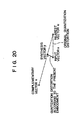
function approximation unit 436 approximates the input vector by using a plurality of code vectors. A variety of function forms are conceivable but approximation in the form of a linear combination of two code vectors will be exemplified. On of the two code vectors is the nearest vector. - The principle of approximating the input vector by using the linear combination of two code vectors will be described with reference to Fig. 20. In Fig. 20, two-dimensional vectors are illustrated for simplicity of explanation.
- A synthesis vector in the form of the linear combination or an approximation vector lies on a straight line connecting the nearest vector u and the complementary vector v. The synthesis vector point takes either an internal division point or an external division point of the vectors u and v depending on sign and magnitude of weight coefficients. Weights of the linear combination are so determined as to minimize the quantization distortion. As is clear from Fig. 20, the quantization distortion can be reduced by approximating the input vector in the form of the linear combination of the two code vectors.
- The two code vectors may be selected from all of combinations of two code vectors but the nearest vector may be selected as one of the code vectors at high probability. Accordingly, it does not matter that the one vector is constantly treated as the nearest vector and in this manner, the quantization distortion can be reduced by the degree comparable to that for selection from all of combinations.
- Where the number of code vectors involved is m, the number of combinations of any two code vectors is given by


- In general, given that the vectors are ℓ-dimensional vectors including an input vector represented by x = {x₁, x₂, ..., xℓ], a nearest vector represented by u = {u, u, ..., uℓ}, and a complementary vector represented by v = {v₁, v₂, ..., vℓ}, a synthesis vector is given bywhere w and (1-w) are
y = wu + (1-w)v (6)
coefficients of a linear combination and the coefficient w is so set as to minimize the approximation error |x-y|. Thesquare error Q D² is then introduced which is

w₁u + w₂v (w₁, w₂: coefficient)
The explanation above mentioned represents the case under the condition of w₁+w₂=1. - In the foregoing, two code vectors are used but a combination (w₁, w₂, ---) of coefficients can also be determined in a similar manner by using three or more code vectors. If the margin of the amount of processing is large, it is not always necessary to stick to the use of the nearest vector but selection may be done from all combinations of a requisite number of code vectors. Further, in the foregoing, the code book is described as being provided by one but obviously a plurality of independent or dependent code books may be used for selection of code vectors having the highest degree of approximation.
- Returning to Fig. 19, the second half of the vector quantizer will be described. The function approximation unit delivers a
code 437 of the candidate vector combined with the nearest vector, acoefficient 438 minimizing the approximation error and an approximation error value (corresponding to quantization error) 439 at that time. Acomplementary vector decider 440 receives the output signals from thefunction approximation unit 436 and thecode 403 of the nearest vector and delivers avector code 109 representative of the codes of the candidate vector minimizing the approximation error and of the nearest vector and the coefficient 110 at that time. - In the foregoing embodiment, the input vector is approximated in the form of a linear combination of a plurality of vectors and the coefficient in the linear combination is so determined as to minimize the approximation error. In an alternative, the coefficient may be determined on the basis of the formula defining the membership function in the fuzzy vector quantization.
- The operation of the receiving station will now be described with reference to Fig 8.
- When a
vector code 109′ is received, a corresponding code vector is read out of thecode book 701. Thevector reconstruction unit 702 responds to the read-out code vector and received coefficient or coefficient set 110′ (in the case of fuzzy vector quantization, 110′ represents the membership function) to reconstruct a vector pursuant to the previously-described equation (6) (in the case of fuzzy vector quantization, equation (4)). The contents of thecode book 701 in the receiving station is the same as that of thecode book 401 in the transmitting station. The reconstructed vector y = {A₁′, A₂′, .., Am′} is sent asspectrum information 115 to the synthesizer 116. - Meritorious effects of this embodiment are graphically demonstrated in Fig. 21 where the quantization distortion is plotted in relation to the code book size. For example, for a quantization distortion of 0.25, the ratio of the code book size in terms of bit number according to the present embodiment to that according to the prior art method is about 1/4 to advantage.
- The voice coding system based on vector quantization according to the invention may also be applied to voice mail systems, voice data multiplex systems, security protection systems, mobile radio systems, voice recognition response systems and voice processing apparatus.
Claims (34)
(a) means for sequentially grouping said parameter values represented by said coefficient values in respect of individual parameter values corresponding to coefficient values of the same order, beginning with a parameter value corresponding to a coefficient value of lower order of said power spectrum and reaching a parameter value corresponding to a coefficient value of higher order of said power spectrum; and
(b) means for hierachically arranging parameter values in respective groups of respective orders,
whereby said input voice vector can be retrieved with priority from globally resembling code vectors.

ℓ = 0, 1, ---, N
N+1: the number of code vectors
µℓk: membership function
dik: the distance between input vector and each code vector
α: weighting coefficient; and

w: coefficient
input vector: xi = {x₁, x₂, ..., xℓ}
nearest vector ui = {u₁, u₂, ..., uℓ}
candidate vectors used for approximation vi = {vi, v₂, ..., vℓ}

where
w:coefficient
y: reconstructed vector
input vector xi = {x₁, x₂, ..., xℓ}
nearest vector ui = {u₁, u₂, ..., uℓ}
candidate vectors used for approximation vi = {v₁, v₂, ..., vℓ}
On the basis of codes of a plurality of received code vectors used for the vector quantization, a coefficient value used for vector approximation in the form of a linear combination in the transmitting station and said stored table.

ℓ= 0, 1, ..., N
N+1: the number of code vectors
µℓk: membership function
dik: the distance between input vector and code vector
α: weighting coefficient; and

w: coefficient
input vector xi = {x₁, x₂, ..., xℓ}
nearest vector ui = {u₁, u₂, ..., uℓ}
candidate vector used for approximation vi = {v₁, v₂, ..., vℓ}.
Applications Claiming Priority (8)
| Application Number | Priority Date | Filing Date | Title |
|---|---|---|---|
| JP240972/88 | 1988-09-28 | ||
| JP63240972A JP3058640B2 (en) | 1988-09-28 | 1988-09-28 | Encoding method |
| JP1057706A JPH02238499A (en) | 1989-03-13 | 1989-03-13 | Vector quantizing system |
| JP57706/89 | 1989-03-13 | ||
| JP1107615A JPH02287500A (en) | 1989-04-28 | 1989-04-28 | Vector quantization system |
| JP107615/89 | 1989-04-28 | ||
| JP1211311A JPH0375700A (en) | 1989-08-18 | 1989-08-18 | Vector quantization system |
| JP211311/89 | 1989-08-18 |
Publications (2)
| Publication Number | Publication Date |
|---|---|
| EP0361443A2 true EP0361443A2 (en) | 1990-04-04 |
| EP0361443A3 EP0361443A3 (en) | 1992-02-26 |
Family
ID=27463545
Family Applications (1)
| Application Number | Title | Priority Date | Filing Date |
|---|---|---|---|
| EP19890117857 Withdrawn EP0361443A3 (en) | 1988-09-28 | 1989-09-27 | Method and system for voice coding based on vector quantization |
Country Status (3)
| Country | Link |
|---|---|
| US (1) | US5077798A (en) |
| EP (1) | EP0361443A3 (en) |
| CA (1) | CA1321645C (en) |
Cited By (3)
| Publication number | Priority date | Publication date | Assignee | Title |
|---|---|---|---|---|
| EP0470941A1 (en) * | 1990-08-10 | 1992-02-12 | Telefonaktiebolaget L M Ericsson | A method of coding a sampled speech signal vector |
| EP0597126A1 (en) * | 1992-05-29 | 1994-05-18 | Studio Gen Inc. | Method for compressing sound information and apparatus for reproducing sound information |
| KR19990066562A (en) * | 1998-01-30 | 1999-08-16 | 전주범 | Template Pattern Matching Method of Speech Recognition Using Fuzzy Mapping Function |
Families Citing this family (25)
| Publication number | Priority date | Publication date | Assignee | Title |
|---|---|---|---|---|
| US5384891A (en) * | 1988-09-28 | 1995-01-24 | Hitachi, Ltd. | Vector quantizing apparatus and speech analysis-synthesis system using the apparatus |
| US5228086A (en) * | 1990-05-18 | 1993-07-13 | Matsushita Electric Industrial Co., Ltd. | Speech encoding apparatus and related decoding apparatus |
| US5271089A (en) * | 1990-11-02 | 1993-12-14 | Nec Corporation | Speech parameter encoding method capable of transmitting a spectrum parameter at a reduced number of bits |
| ES2166355T3 (en) * | 1991-06-11 | 2002-04-16 | Qualcomm Inc | VARIABLE SPEED VOCODIFIER. |
| JP2870224B2 (en) * | 1991-06-19 | 1999-03-17 | 松下電器産業株式会社 | Voice recognition method |
| US5487086A (en) * | 1991-09-13 | 1996-01-23 | Comsat Corporation | Transform vector quantization for adaptive predictive coding |
| DE4239506A1 (en) * | 1992-11-25 | 1994-05-26 | Inst Rundfunktechnik Gmbh | Reduced-bit-rate source coding method for digital audio signal transmission - applying neural network or fuzzy logic in all or parts of encoding and decoding procedures |
| KR970011859B1 (en) * | 1993-04-15 | 1997-07-18 | 삼성전자 주식회사 | Encoding method and device for using fuzzy control |
| US5615298A (en) * | 1994-03-14 | 1997-03-25 | Lucent Technologies Inc. | Excitation signal synthesis during frame erasure or packet loss |
| JP2956473B2 (en) * | 1994-04-21 | 1999-10-04 | 日本電気株式会社 | Vector quantizer |
| TW271524B (en) | 1994-08-05 | 1996-03-01 | Qualcomm Inc | |
| US5797118A (en) * | 1994-08-09 | 1998-08-18 | Yamaha Corporation | Learning vector quantization and a temporary memory such that the codebook contents are renewed when a first speaker returns |
| US5742734A (en) * | 1994-08-10 | 1998-04-21 | Qualcomm Incorporated | Encoding rate selection in a variable rate vocoder |
| JP3308764B2 (en) * | 1995-05-31 | 2002-07-29 | 日本電気株式会社 | Audio coding device |
| US5751901A (en) * | 1996-07-31 | 1998-05-12 | Qualcomm Incorporated | Method for searching an excitation codebook in a code excited linear prediction (CELP) coder |
| US6081781A (en) * | 1996-09-11 | 2000-06-27 | Nippon Telegragh And Telephone Corporation | Method and apparatus for speech synthesis and program recorded medium |
| SE9804455L (en) * | 1998-12-21 | 2000-06-22 | Ericsson Telefon Ab L M | Procedure and arrangement for finding an optimal reconstruction point |
| US6725190B1 (en) * | 1999-11-02 | 2004-04-20 | International Business Machines Corporation | Method and system for speech reconstruction from speech recognition features, pitch and voicing with resampled basis functions providing reconstruction of the spectral envelope |
| US7809556B2 (en) * | 2004-03-05 | 2010-10-05 | Panasonic Corporation | Error conceal device and error conceal method |
| MX2007012184A (en) * | 2005-04-01 | 2007-12-11 | Qualcomm Inc | Systems, methods, and apparatus for wideband speech coding. |
| EP1875463B1 (en) | 2005-04-22 | 2018-10-17 | Qualcomm Incorporated | Systems, methods, and apparatus for gain factor smoothing |
| US8335684B2 (en) * | 2006-07-12 | 2012-12-18 | Broadcom Corporation | Interchangeable noise feedback coding and code excited linear prediction encoders |
| US7477192B1 (en) | 2007-02-22 | 2009-01-13 | L-3 Communications Titan Corporation | Direction finding system and method |
| TWI618050B (en) | 2013-02-14 | 2018-03-11 | 杜比實驗室特許公司 | Method and apparatus for signal decorrelation in an audio processing system |
| EP3011562A2 (en) * | 2013-06-17 | 2016-04-27 | Dolby Laboratories Licensing Corporation | Multi-stage quantization of parameter vectors from disparate signal dimensions |
Family Cites Families (3)
| Publication number | Priority date | Publication date | Assignee | Title |
|---|---|---|---|---|
| JPS61252596A (en) * | 1985-05-02 | 1986-11-10 | 株式会社日立製作所 | Character voice communication system and apparatus |
| IT1184023B (en) * | 1985-12-17 | 1987-10-22 | Cselt Centro Studi Lab Telecom | PROCEDURE AND DEVICE FOR CODING AND DECODING THE VOICE SIGNAL BY SUB-BAND ANALYSIS AND VECTORARY QUANTIZATION WITH DYNAMIC ALLOCATION OF THE CODING BITS |
| IT1195350B (en) * | 1986-10-21 | 1988-10-12 | Cselt Centro Studi Lab Telecom | PROCEDURE AND DEVICE FOR THE CODING AND DECODING OF THE VOICE SIGNAL BY EXTRACTION OF PARA METERS AND TECHNIQUES OF VECTOR QUANTIZATION |
-
1989
- 1989-09-26 US US07/412,987 patent/US5077798A/en not_active Expired - Fee Related
- 1989-09-26 CA CA000613182A patent/CA1321645C/en not_active Expired - Fee Related
- 1989-09-27 EP EP19890117857 patent/EP0361443A3/en not_active Withdrawn
Non-Patent Citations (4)
| Title |
|---|
| 11IéME COLLOQUE GRETSI, 1 June 1987, NICE, FRANCE; pages 455 - 458; G. ZANELLATO: 'Quantification vectorielle souple, base de la reconnaissance de la parole' * |
| ICASSP 87 PROCEEDINGS, vol. 2/4, 6 April 1987, DALLAS, US; pages 641 - 644; H.P. TSENG ET AL.: 'Fuzzy vector quantization applied to hidden markov modeling' * |
| ICASSP 89, vol. 1, 23 May 1989, GLASGOW, GB; pages 89 - 92; S. NAKAMURA ET AL.: 'Speaker adaptation applied to HMM and neural networks' * |
| ICASSP 89, vol. 2, 23 May 1989, GLASGOW, GB; pages 755 - 758; Y. ASAKAWA ET AL.: 'Speech coding method using fuzzy vector quantization' * |
Cited By (6)
| Publication number | Priority date | Publication date | Assignee | Title |
|---|---|---|---|---|
| EP0470941A1 (en) * | 1990-08-10 | 1992-02-12 | Telefonaktiebolaget L M Ericsson | A method of coding a sampled speech signal vector |
| WO1992002927A1 (en) * | 1990-08-10 | 1992-02-20 | Telefonaktiebolaget Lm Ericsson | A method of coding a sampled speech signal vector |
| US5214706A (en) * | 1990-08-10 | 1993-05-25 | Telefonaktiebolaget Lm Ericsson | Method of coding a sampled speech signal vector |
| EP0597126A1 (en) * | 1992-05-29 | 1994-05-18 | Studio Gen Inc. | Method for compressing sound information and apparatus for reproducing sound information |
| EP0597126A4 (en) * | 1992-05-29 | 1997-01-08 | Studio Gen Inc | Method for compressing sound information and apparatus for reproducing sound information. |
| KR19990066562A (en) * | 1998-01-30 | 1999-08-16 | 전주범 | Template Pattern Matching Method of Speech Recognition Using Fuzzy Mapping Function |
Also Published As
| Publication number | Publication date |
|---|---|
| CA1321645C (en) | 1993-08-24 |
| US5077798A (en) | 1991-12-31 |
| EP0361443A3 (en) | 1992-02-26 |
Similar Documents
| Publication | Publication Date | Title |
|---|---|---|
| US5077798A (en) | Method and system for voice coding based on vector quantization | |
| US5384891A (en) | Vector quantizing apparatus and speech analysis-synthesis system using the apparatus | |
| US7035791B2 (en) | Feature-domain concatenative speech synthesis | |
| US4184049A (en) | Transform speech signal coding with pitch controlled adaptive quantizing | |
| Buzo et al. | Speech coding based upon vector quantization | |
| US4771465A (en) | Digital speech sinusoidal vocoder with transmission of only subset of harmonics | |
| CA1338387C (en) | Vector excitation speech or audio coder for transmission or storage | |
| US6078880A (en) | Speech coding system and method including voicing cut off frequency analyzer | |
| EP1339040B1 (en) | Vector quantizing device for lpc parameters | |
| US6681204B2 (en) | Apparatus and method for encoding a signal as well as apparatus and method for decoding a signal | |
| US6119082A (en) | Speech coding system and method including harmonic generator having an adaptive phase off-setter | |
| US7065338B2 (en) | Method, device and program for coding and decoding acoustic parameter, and method, device and program for coding and decoding sound | |
| US6094629A (en) | Speech coding system and method including spectral quantizer | |
| US6138092A (en) | CELP speech synthesizer with epoch-adaptive harmonic generator for pitch harmonics below voicing cutoff frequency | |
| EP0500961A1 (en) | Voice coding system | |
| EP0780831B1 (en) | Coding of a speech or music signal with quantization of harmonics components specifically and then of residue components | |
| US5794185A (en) | Method and apparatus for speech coding using ensemble statistics | |
| EP1239458B1 (en) | Voice recognition system, standard pattern preparation system and corresponding methods | |
| WO2005041169A2 (en) | Method and system for speech coding | |
| US4969193A (en) | Method and apparatus for generating a signal transformation and the use thereof in signal processing | |
| US5583888A (en) | Vector quantization of a time sequential signal by quantizing an error between subframe and interpolated feature vectors | |
| US5142583A (en) | Low-delay low-bit-rate speech coder | |
| EP1771841B1 (en) | Method for generating and using a vector codebook, method and device for compressing data, and distributed speech recognition system | |
| AU676392B2 (en) | Multipulse processing with freedom given to multipulse positions of a speech signal | |
| US5822721A (en) | Method and apparatus for fractal-excited linear predictive coding of digital signals |
Legal Events
| Date | Code | Title | Description |
|---|---|---|---|
| PUAI | Public reference made under article 153(3) epc to a published international application that has entered the european phase |
Free format text: ORIGINAL CODE: 0009012 |
|
| AK | Designated contracting states |
Kind code of ref document: A2 Designated state(s): DE FR GB IT NL |
|
| 17P | Request for examination filed |
Effective date: 19901220 |
|
| PUAL | Search report despatched |
Free format text: ORIGINAL CODE: 0009013 |
|
| AK | Designated contracting states |
Kind code of ref document: A3 Designated state(s): DE FR GB IT NL |
|
| 17Q | First examination report despatched |
Effective date: 19940720 |
|
| STAA | Information on the status of an ep patent application or granted ep patent |
Free format text: STATUS: THE APPLICATION IS DEEMED TO BE WITHDRAWN |
|
| 18D | Application deemed to be withdrawn |
Effective date: 19950131 |