EP0361296B1 - System for reading and coding a magnetic track, carried by a document, by manually moving the document - Google Patents
System for reading and coding a magnetic track, carried by a document, by manually moving the document Download PDFInfo
- Publication number
- EP0361296B1 EP0361296B1 EP89117374A EP89117374A EP0361296B1 EP 0361296 B1 EP0361296 B1 EP 0361296B1 EP 89117374 A EP89117374 A EP 89117374A EP 89117374 A EP89117374 A EP 89117374A EP 0361296 B1 EP0361296 B1 EP 0361296B1
- Authority
- EP
- European Patent Office
- Prior art keywords
- head
- message
- magnetic
- write
- read
- Prior art date
- Legal status (The legal status is an assumption and is not a legal conclusion. Google has not performed a legal analysis and makes no representation as to the accuracy of the status listed.)
- Expired - Lifetime
Links
Images
Classifications
-
- G—PHYSICS
- G06—COMPUTING; CALCULATING OR COUNTING
- G06K—GRAPHICAL DATA READING; PRESENTATION OF DATA; RECORD CARRIERS; HANDLING RECORD CARRIERS
- G06K7/00—Methods or arrangements for sensing record carriers, e.g. for reading patterns
- G06K7/08—Methods or arrangements for sensing record carriers, e.g. for reading patterns by means detecting the change of an electrostatic or magnetic field, e.g. by detecting change of capacitance between electrodes
-
- G—PHYSICS
- G07—CHECKING-DEVICES
- G07F—COIN-FREED OR LIKE APPARATUS
- G07F7/00—Mechanisms actuated by objects other than coins to free or to actuate vending, hiring, coin or paper currency dispensing or refunding apparatus
- G07F7/02—Mechanisms actuated by objects other than coins to free or to actuate vending, hiring, coin or paper currency dispensing or refunding apparatus by keys or other credit registering devices
-
- G—PHYSICS
- G06—COMPUTING; CALCULATING OR COUNTING
- G06K—GRAPHICAL DATA READING; PRESENTATION OF DATA; RECORD CARRIERS; HANDLING RECORD CARRIERS
- G06K1/00—Methods or arrangements for marking the record carrier in digital fashion
- G06K1/12—Methods or arrangements for marking the record carrier in digital fashion otherwise than by punching
- G06K1/125—Methods or arrangements for marking the record carrier in digital fashion otherwise than by punching by magnetic means
-
- G—PHYSICS
- G06—COMPUTING; CALCULATING OR COUNTING
- G06K—GRAPHICAL DATA READING; PRESENTATION OF DATA; RECORD CARRIERS; HANDLING RECORD CARRIERS
- G06K7/00—Methods or arrangements for sensing record carriers, e.g. for reading patterns
- G06K7/08—Methods or arrangements for sensing record carriers, e.g. for reading patterns by means detecting the change of an electrostatic or magnetic field, e.g. by detecting change of capacitance between electrodes
- G06K7/082—Methods or arrangements for sensing record carriers, e.g. for reading patterns by means detecting the change of an electrostatic or magnetic field, e.g. by detecting change of capacitance between electrodes using inductive or magnetic sensors
- G06K7/083—Methods or arrangements for sensing record carriers, e.g. for reading patterns by means detecting the change of an electrostatic or magnetic field, e.g. by detecting change of capacitance between electrodes using inductive or magnetic sensors inductive
- G06K7/084—Methods or arrangements for sensing record carriers, e.g. for reading patterns by means detecting the change of an electrostatic or magnetic field, e.g. by detecting change of capacitance between electrodes using inductive or magnetic sensors inductive sensing magnetic material by relative movement detecting flux changes without altering its magnetised state
-
- G—PHYSICS
- G06—COMPUTING; CALCULATING OR COUNTING
- G06Q—INFORMATION AND COMMUNICATION TECHNOLOGY [ICT] SPECIALLY ADAPTED FOR ADMINISTRATIVE, COMMERCIAL, FINANCIAL, MANAGERIAL OR SUPERVISORY PURPOSES; SYSTEMS OR METHODS SPECIALLY ADAPTED FOR ADMINISTRATIVE, COMMERCIAL, FINANCIAL, MANAGERIAL OR SUPERVISORY PURPOSES, NOT OTHERWISE PROVIDED FOR
- G06Q20/00—Payment architectures, schemes or protocols
- G06Q20/30—Payment architectures, schemes or protocols characterised by the use of specific devices or networks
- G06Q20/34—Payment architectures, schemes or protocols characterised by the use of specific devices or networks using cards, e.g. integrated circuit [IC] cards or magnetic cards
- G06Q20/343—Cards including a counter
- G06Q20/3437—Cards including a counter the counter having non-monetary units, e.g. trips
Definitions
- a known solution consists in doubling the magnetic track by a parallel magnetic track on which a clock signal is recorded, an additional read head is thus necessary to read this clock signal which makes it possible to synchronize the writing and to make it independent of the speed of passage of the title.
- the read head 9 begins to read the fixed message MF.
Landscapes
- Engineering & Computer Science (AREA)
- General Physics & Mathematics (AREA)
- Physics & Mathematics (AREA)
- Theoretical Computer Science (AREA)
- Business, Economics & Management (AREA)
- Computer Vision & Pattern Recognition (AREA)
- Artificial Intelligence (AREA)
- Microelectronics & Electronic Packaging (AREA)
- Computer Networks & Wireless Communication (AREA)
- Accounting & Taxation (AREA)
- Strategic Management (AREA)
- General Business, Economics & Management (AREA)
- Signal Processing For Digital Recording And Reproducing (AREA)
- Recording Or Reproducing By Magnetic Means (AREA)
- Credit Cards Or The Like (AREA)
- Control Of Vending Devices And Auxiliary Devices For Vending Devices (AREA)
Description
La présente invention concerne un système pour la lecture et l'encodage d'une piste magnétique portée par un document support, par déplacement manuel du document.The present invention relates to a system for reading and encoding a magnetic stripe carried by a support document, by manual movement of the document.
L'invention s'applique en particulier pour des titres de transport à piste magnétique comportant un message fixe d'identification du titre et un message variable représentatif d'unités de transport. Il s'agit donc dans cette application particulière d'un système de transport à titre à décompte.The invention applies in particular to tickets with magnetic stripes comprising a fixed ticket identification message and a variable message representative of transport units. In this particular application, it is therefore a transport system on account.
Il existe des bornes de péage permettant de traiter de tels titres de transport, ces bornes sont équipées de lecteurs/enregistreurs motorisés, c'est-à-dire que l'usager introduit son titre de transport dans une goulotte ou une fente et que celui-ci est entraîné automatiquement vers le lecteur-enregistreur, le titre étant ensuite restitué, soit par une sortie distincte de l'introduction, soit par l'orifice de l'introduction lui-même après avoir effectué un aller et retour.There are toll kiosks for processing such tickets, these kiosks are equipped with motorized readers / recorders, that is to say that the user introduces his ticket in a chute or slot and that -this is automatically driven to the reader-recorder, the title then being returned, either by a separate output from the introduction, or by the opening of the introduction itself after having made a round trip.
Il existe également des bornes de péage où les usagers passent eux-mêmes leur titre de transport dans une glissière conduisant devant un lecteur, mais sans se dessaisir de leur titre. Dans ce dernier cas, le titre de transport est forfaitaire, et il ne s'agit pas d'un titre à décompte et la borne de péage ne comporte qu'un lecteur, mais non pas de tête d'écriture.There are also toll kiosks where users themselves pass their ticket in a slide leading to a reader, but without relinquishing their ticket. In the latter case, the transport ticket is a flat rate, and it is not a countdown ticket and the toll booth only has a reader, but not a writing head.
En effet, l'écriture nécessite que la densité linéaire des bits du codage magnétique utilisé, soit indépendante de la vitesse et des variations de vitesse de passage du titre de transport devant une tête d'écriture, ceci conduit à une complication lorsque le titre est déplacé manuellement.Indeed, writing requires that the linear density of the bits of the magnetic coding used, be independent of the speed and variations in speed of passage of the transport ticket in front of a writing head, this leads to a complication when the ticket is moved manually.
Une solution connue consiste à doubler la piste magnétique par une piste magnétique parallèle sur laquelle est enregistré un signal d'horloge, une tête de lecture supplémentaire est ainsi nécessaire pour lire ce signal d'horloge qui permet de synchroniser l'écriture et de la rendre indépendante de la vitesse de passage du titre.A known solution consists in doubling the magnetic track by a parallel magnetic track on which a clock signal is recorded, an additional read head is thus necessary to read this clock signal which makes it possible to synchronize the writing and to make it independent of the speed of passage of the title.
L'invention a pour but de proposer un système à déplacement manuel d'un document support portant une piste magnétique dont une partie est porteuse d'un message fixe et dont une autre partie comporte un message variable, qui ne nécessite pas de piste supplémentaire pourvue d'un signal d'horloge, ni de tête magnétique supplémentaire.The object of the invention is to propose a system for manually moving a support document carrying a magnetic track, part of which is carrying a fixed message and of which another part comprises a variable message, which does not require an additional track provided with a clock signal, nor an additional magnetic head.
Le système à déplacement manuel présente en effet des avantages. Tout d'abord, il évite une motorisation nécessitant des éléments mécaniques complexes, en outre, il est moins vulnérable au vandalisme.The manual displacement system has advantages. First of all, it avoids a motorization requiring complex mechanical elements, in addition, it is less vulnerable to vandalism.
L'invention a ainsi pour objet un système pour la lecture et l'encodage d'une piste magnétique portée par un document support, par déplacement manuel du document devant des organes de lecture et d'écriture, la piste magnétique comportant une première partie sur laquelle est enregistré un premier message codé fixe, caractéristique du document support, ledit message étant réalisé dans un système de codage auto-porteur de son signal d'horloge, suivi d'une seconde partie réservée à l'inscription d'un second message variable inscrit à chaque passage du document support devant lesdits organes de lecture et d'écriture, caractérisé en ce que le dispositif de lecture-écriture comprend trois têtes magnétiques alignées, dont la première est une tête de lecture, la seconde une tête d'écriture et la troisième une tête de lecture, la tête d'écriture étant reliée à un générateur de signal d'écriture recevant en entrée, d'une part les données dudit message variable à enregistrer sur ladite seconde partie de la piste magnétique ces données étant fournies par un module de traitement (20) recevant des informations de la première tête de lecture (9), et d'autre part un signal d'horloge élaboré par un circuit électronique recevant en entrée les signaux provenant de ladite troisième tête, de lecture, et extrayant le signal d'horloge dudit message codé fixe enregistré sur ladite première partie de la piste magnétique, l'arrivée du signal d'horloge sur le générateur de signal d'écriture déclenchant ladite écriture, la longueur linéaire du message variable étant au plus égale à la longueur du message fixe et la distance séparant la seconde tête magnétique de la troisième tête magnétique étant telle que le déclenchement de l'écriture ne se produise pas avant que la fin du message fixe soit complétement passé devant ladite seconde tête, d'écriture, et telle qu'il reste une longueur suffisante de piste magnétique pour l'enregistrement du message variable, la distance séparant la première tête magnétique de la seconde tête magnétique étant au moins égale à la longueur linéaire du message variable.The subject of the invention is therefore a system for reading and encoding a magnetic strip carried by a support document, by manual movement of the document in front of reading and writing members, the magnetic strip comprising a first part on which is recorded a first fixed coded message, characteristic of the support document, said message being produced in a self-carrying coding system of its clock signal, followed by a second part reserved for the recording of a second variable message written at each passage of the support document in front of said reading and writing members, characterized in that the read-write device comprises three aligned magnetic heads, the first of which is a read head, the second of which is a write head and the third a read head, the write head being connected to a write signal generator receiving, on the one hand, the data of said vari message able to record on said second part of the magnetic strip this data being supplied by a processing module (20) receiving information from the first read head (9), and on the other hand a clock signal produced by a circuit electronics receiving as input the signals from said third head, for reading, and extracting the clock signal from said fixed coded message recorded on said first part of the magnetic strip, the arrival of the clock signal on the signal generator d writing triggering said writing, the linear length of the variable message being at most equal to the length of the fixed message and the distance separating the second magnetic head from the third magnetic head being such that the triggering of the writing does not occur before the end of the fixed message is completely passed in front of said second writing head, and such that there is a sufficient length of magnetic stripe for recording the variable message, the distance separating the first magnetic head from the second magnetic head being at least equal to the linear length of the variable message.
Des systèmes pour la lecture et l'encodage d'une piste magnétique sont connus des brevets américains US-A-4 507 550 et US-A-4 228 348.Systems for reading and encoding a magnetic strip are known from American patents US-A-4,507,550 and US-A-4,228,348.
On va maintenant donner la description d'un exemple particulier de mise en oeuvre de l'invention dans le cas de son application à des titres de transport, en se référant au dessin annexé dans lequel :
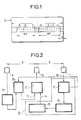
- La figure 1 représente un support muni d'une piste magnétique utilisé comme titre de transport.
- La figure 2 représente schématiquement un système selon l'invention permettant de lire et d'écrire sur la piste magnétique du support représenté figure 1, par déplacement manuel du support devant les organes de lecture et d'écriture.
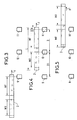
- Les figures 3, 4 et 5 sont des schémas figurant trois positions caractéristiques du support par rapport aux têtes magnétiques au cours de son déplacement manuel devant ces têtes magnétiques.
- FIG. 1 represents a support provided with a magnetic track used as a transport ticket.
- FIG. 2 schematically represents a system according to the invention making it possible to read and write on the magnetic track of the support shown in FIG. 1, by manual movement of the support in front of the reading and writing members.
- Figures 3, 4 and 5 are diagrams showing three characteristic positions of the support relative to the magnetic heads during its manual movement in front of these magnetic heads.
La figure 1 représente un titre de transport 1 qui comporte une piste magnétique 2. Sur cette piste magnétique 2 est enregistré un message fixe invariable sur la partie droite 3 de la piste 2. Les traits verticaux 4 et 5 symbolisent le début et la fin de ce message fixe dont la longueur est symbolisée par les lettres MF. Ce message fixe est un message de validation du titre de transport. Sur la partie gauche 6 de la piste magnétique 2 est enregistré un message variable qui est écrit à chaque passage du titre devant le système de lecture et d'encodage, disposé dans une borne d'accès à une enceinte permettant d'utiliser un moyen de transport. Ce message variable consiste en un code représentant, par exemple, un certain nombre d'unités de transport, ce nombre étant décrémenté à chaque passage devant un tel système. Les traits verticaux 7 et 8 symbolisent le début et la fin de ce message variable dont la longueur est symbolisée par les lettres MV. La lettre L symbolise la longueur totale de la piste magnétique 2 et la lettre a symbolise la longueur de piste avant le début du message fixe. Le message fixe MF est réalisé dans un système de codage auto-porteur de son signal d'horloge, tel que par exemple les codes F/2F ; split phase...FIG. 1 represents a transport ticket 1 which includes a
En se reportant à la figure 2, le système de lecture et d'encodage comporte d'abord des organes de lecture et d'écriture comprenant trois têtes magnétiques alignées : une première tête magnétique 9 qui est une tête de lecture, une deuxième tête magnétique 10 qui est une tête d'écriture et une troisième tête magnétique 11 qui est une tête de lecture.Referring to FIG. 2, the reading and encoding system first comprises reading and writing members comprising three aligned magnetic heads: a first
La tête d'écriture 10 reçoit un signal d'écriture produit par un générateur de signal d'écriture 12 qui reçoit, d'une part sur une entrée 13 les données variables à enregistrer sur la portion 6 de la piste magnétique 2, et d'autre part sur une entrée 14 un signal d'horloge d'écriture élaboré par un circuit électronique 15. Les données variables envoyées sur l'entrée 13 sont fournies par un module de traitement 20. Ce module de traitement 20 reçoit des informations d'un module de décodage 21 relié à la première tête de lecture 9. Le circuit électronique 15 reçoit en entrée 16 les signaux provenant de la tête de lecture 11. Il comprend d'abord un module de lecture-décodage 17. Dans ce module, lors du passage du message fixe MF devant la tête de lecture 11, les transitions magnétiques du message fixe enregistrées sur la piste sont lues et décodées, et le signal d'horloge est séparé des données extraites du signal reçu. Le circuit électronique 15 comprend ensuite un module d'analyse-asservissement 18. En fonction de la vitesse de défilement du titre de transport 1 devant la tête de lecture 11, l'écart de temps entre les différents "bits" vu par la tête 11 varie. Le module 18 mesure l'écart de temps entre chaque transition, et recalcule le rythme de base qui servira à établir le signal d'horloge pour l'écriture.The
Enfin, le circuit électronique 15 comprend un générateur de signal d'horloge d'écriture 19 qui réalise le signal d'horloge asservi à la vitesse de défilement du titre de transport 1, à partir des éléments de calculs consécutifs à l'analyse réalisée par le module d'analyse-asservissement 18. Le module de lecture-décodage 17 est d'autre part relié au module de traitement 20.Finally, the
L'arrivée du signal d'horloge d'écriture sur l'entrée 14 du générateur de signal d'écriture 12 déclenche, en présence de données sur l'entrée 13, la génération du signal d'écriture.The arrival of the write clock signal on the input 14 of the
L'ensemble du système est disposé dans une borne de passage, les trois têtes magnétiques 9, 10 et 11 étant alignées en face d'une fente longitudinale le long de laquelle l'usager fait glisser manuellement son titre de transport 1.The entire system is arranged in a passage terminal, the three
Les figures 3, 4 et 5 montrent différentes étapes du passage du titre devant les têtes magnétiques. Sur ces figures, on n'a figuré que la piste magnétique 2 et les trois têtes magnétiques 9, 10 et 11. La flèche F indique le sens de déplacement du titre porteur de la piste 2.Figures 3, 4 and 5 show different stages of the passage of the title in front of the magnetic heads. In these figures, only the
Dans la position représentée sur la figure 3, la tête de lecture 9 commence à lire le message fixe MF.In the position shown in FIG. 3, the read
Dans la position représentée sur la figure 4, le début du message fixe MF a atteint la tête de lecture 11, ce qui a pour effet de déclencher le fonctionnement de la tête d'écriture 10. Dans cette position, la tête de lecture 9 a terminé sa lecture complète des messages fixe MF et variable MV du titre de transport et le module de traitement 20 peut donc fournir sur l'entrée 13 les nouvelles données à enregistrer.In the position shown in FIG. 4, the start of the fixed message MF has reached the
Enfin, dans la position représentée sur la figure 5, l'écriture du message variable MV est terminée, et la tête de lecture 11 atteint le début du message variable MV nouvellement inscrit qui sera ainsi contrôlé grâce au module de lecture-décodage 17 et de traitement 20.Finally, in the position shown in FIG. 5, the writing of the variable message MV is finished, and the
Pour pouvoir obtenir le signal d'horloge d'écriture, nécessaire à l'écriture du message variable MV, qui est généré grâce à la lecture du message fixe MF par la tête de lecture 11, il est nécessaire que la longueur linéaire du message variable soit au plus égale à la longueur du message fixe. On doit donc avoir MV ≦ MF.In order to be able to obtain the write clock signal, necessary for writing the variable message MV, which is generated by reading the fixed message MF by the
Par ailleurs, la distance D entre la seconde tête magnétique 10 et la troisième tête magnétique 11 doit être telle que le déclenchement de l'écriture ne se produise pas avant que la fin du message fixe soit complétement passé devant la seconde tête 10. Il faut également que cette distance D soit telle qu'il reste une longueur suffisante de piste magnétique 2 pour l'enregistrement complet du message variable. On doit donc avoir : ![]()
![]()
![]()
![]()
Enfin, afin que les nouvelles données d'écriture puissent être élaborées par le module de traitement 20, il faut que la tête de lecture 9 ait terminé la lecture du message variable MV, il faut donc que la distance D₁ entre la tête de lecture 9 et la tête d'écriture 10 soit au moins égale à la longueur MV du message variable.Finally, so that the new writing data can be produced by the
A titre de sécurité, pour éviter tout risque d'effacement du message fixe par suite d'une mauvaise manipulation du titre de transport devant les têtes magnétiques, un capteur peut valider l'écriture lorsque la tête d'écriture 10 est en bonne position pour écrire.As a security measure, to avoid any risk of erasing the fixed message as a result of improper handling of the ticket in front of the magnetic heads, a sensor can validate the writing when the
Claims (1)
- A system for reading and encoding a magnetic track (2) carried by a supporting document (1) which is displaced manually past read and write members, the magnetic track comprising a first portion (3) on which a fixed first encoded message characteristic of the supporting document is recorded, said message being encoded by means of an encoding system which conveys its own clock signal, the first portion of the track being followed by a second portion (6) in which a variable second encoded message is written each time the supporting document goes past said read and write members, the system being characterized in that the read and write members comprise three magnetic heads in alignment, comprising a first head (9) which is a read head, a second head (10) which is a write head, and a third head (11) which is a read head, the write head (10) being connected to a write signal generator (12) having a first input (13) which receives data representative of said variable message to be recorded on said second portion of the magnetic track, the data being supplied by a treatment module (20) receiving information from the first read head (9), and a second input (14) on which it receives a clock signal generated by an electronic circuit (15) having an input (16) on which it receives the signals from the said read third head (11), and serving to extract the clock signal from said fixed encoded message recorded on said first portion (3) of the magnetic track (2), the arrival of the clock signal (14) at the write signal generator (12) triggering said writing, the linear length (MV) of the variable message being no longer than the length (MF) of the fixed message, and the distance (D) between the second magnetic head (10) and the third magnetic head (11) being such that writing is not triggered until the end of the fixed message has gone completely past said write second head (10), and such that there remains a sufficient length of the magnetic track (2) to record the variable message, the distance (D1) between the first magnetic head (9) and the second magnetic head (10) being not less than the linear length (MV) of the variable message.
Priority Applications (1)
| Application Number | Priority Date | Filing Date | Title |
|---|---|---|---|
| AT89117374T ATE96561T1 (en) | 1988-09-27 | 1989-09-20 | SYSTEM FOR SENSING AND ENCODING A MAGNETIC TRACK CARRIED OUT BY A DOCUMENT WHEN MOVING THE DOCUMENT BY HAND. |
Applications Claiming Priority (2)
| Application Number | Priority Date | Filing Date | Title |
|---|---|---|---|
| FR8812608 | 1988-09-27 | ||
| FR8812608A FR2637102B1 (en) | 1988-09-27 | 1988-09-27 | SYSTEM FOR READING AND ENCODING A MAGNETIC TRACK CARRIED BY A SUPPORTED DOCUMENT, BY MANUAL MOVING OF THE DOCUMENT |
Publications (2)
| Publication Number | Publication Date |
|---|---|
| EP0361296A1 EP0361296A1 (en) | 1990-04-04 |
| EP0361296B1 true EP0361296B1 (en) | 1993-10-27 |
Family
ID=9370434
Family Applications (1)
| Application Number | Title | Priority Date | Filing Date |
|---|---|---|---|
| EP89117374A Expired - Lifetime EP0361296B1 (en) | 1988-09-27 | 1989-09-20 | System for reading and coding a magnetic track, carried by a document, by manually moving the document |
Country Status (9)
| Country | Link |
|---|---|
| US (1) | US5028768A (en) |
| EP (1) | EP0361296B1 (en) |
| JP (1) | JPH0648586B2 (en) |
| KR (1) | KR970007278B1 (en) |
| AR (1) | AR242866A1 (en) |
| AT (1) | ATE96561T1 (en) |
| DE (1) | DE68910258T2 (en) |
| ES (1) | ES2045322T3 (en) |
| FR (1) | FR2637102B1 (en) |
Families Citing this family (9)
| Publication number | Priority date | Publication date | Assignee | Title |
|---|---|---|---|---|
| JP2549507Y2 (en) * | 1991-03-26 | 1997-09-30 | オムロン株式会社 | Magnetic card reader |
| FR2682205B1 (en) * | 1991-10-04 | 1993-11-19 | Cga Hbs Cie Gle Automatisme | METHOD FOR RECORDING A NEW CODE MESSAGE, INSTEAD OF AN ANCIENT CODE MESSAGE RECORDED ON A MAGNETIC TRACK CARRIED BY A SUPPORTED DOCUMENT, BY MANUAL MOVEMENT OF SAID DOCUMENT AND SYSTEM FOR IMPLEMENTING THE PROCESS. |
| GB2272560B (en) * | 1992-11-14 | 1996-07-17 | Thorn Secure Science Ltd | Writing of a second set of data in dependence upon reading a first set of data |
| DE4311941A1 (en) * | 1993-04-10 | 1994-11-03 | Designa Verkehrsleittech Gmbh | Method and device for determining parking fees |
| US5736722A (en) * | 1996-02-08 | 1998-04-07 | Eastman Kodak Company | Dual sensor decoder |
| EP0993648A4 (en) * | 1997-12-01 | 2002-08-07 | Innovonics Inc | Methods and apparatus for writing to tracks on magnetic-stripe cards |
| US6336149B1 (en) * | 1999-01-26 | 2002-01-01 | Glenn W. Preston | Macro recording and playback device independent of operating system or application software and method of using same |
| DE10141095C2 (en) * | 2001-08-22 | 2003-06-18 | Wincor Nixdorf Int Gmbh | Method for improving the reading of magnetic track data when inserting a card into a DIP reader |
| US7896248B2 (en) * | 2009-06-10 | 2011-03-01 | Rem Holdings 3, Llc | Card reader device and method of use |
Family Cites Families (7)
| Publication number | Priority date | Publication date | Assignee | Title |
|---|---|---|---|---|
| US3869700A (en) * | 1972-12-26 | 1975-03-04 | Ibm | Stored value system |
| US4024379A (en) * | 1975-05-19 | 1977-05-17 | Service Distributors, Inc. | Binary system for magnetic card actuation for laundry machines |
| JPS523413A (en) * | 1975-06-26 | 1977-01-11 | Sankyo Seiki Mfg Co Ltd | Magnetic recording device |
| GB1593377A (en) * | 1976-12-10 | 1981-07-15 | Emi Ltd | Security document and system |
| FR2414756A1 (en) * | 1978-01-11 | 1979-08-10 | Automatisme Cie Gle | MAGNETIC CODING METHOD AND DEVICE THAT CAN BE MODIFIED BY OVERLAYING A FIXED CODE |
| US4507550A (en) * | 1983-05-13 | 1985-03-26 | Umc Industries, Inc. | High security credit card, system and method |
| US4645916A (en) * | 1983-09-09 | 1987-02-24 | Eltrax Systems, Inc. | Encoding method and related system and product |
-
1988
- 1988-09-27 FR FR8812608A patent/FR2637102B1/en not_active Expired - Fee Related
-
1989
- 1989-09-20 ES ES89117374T patent/ES2045322T3/en not_active Expired - Lifetime
- 1989-09-20 DE DE89117374T patent/DE68910258T2/en not_active Expired - Lifetime
- 1989-09-20 EP EP89117374A patent/EP0361296B1/en not_active Expired - Lifetime
- 1989-09-20 AT AT89117374T patent/ATE96561T1/en not_active IP Right Cessation
- 1989-09-21 US US07/410,448 patent/US5028768A/en not_active Expired - Fee Related
- 1989-09-25 JP JP1248981A patent/JPH0648586B2/en not_active Expired - Lifetime
- 1989-09-26 KR KR1019890013824A patent/KR970007278B1/en not_active IP Right Cessation
- 1989-09-28 AR AR89315048A patent/AR242866A1/en active
Also Published As
| Publication number | Publication date |
|---|---|
| JPH02134772A (en) | 1990-05-23 |
| FR2637102B1 (en) | 1990-11-16 |
| JPH0648586B2 (en) | 1994-06-22 |
| FR2637102A1 (en) | 1990-03-30 |
| EP0361296A1 (en) | 1990-04-04 |
| AR242866A1 (en) | 1993-05-31 |
| ES2045322T3 (en) | 1994-01-16 |
| DE68910258T2 (en) | 1994-02-24 |
| DE68910258D1 (en) | 1993-12-02 |
| ATE96561T1 (en) | 1993-11-15 |
| US5028768A (en) | 1991-07-02 |
| KR900005330A (en) | 1990-04-14 |
| KR970007278B1 (en) | 1997-05-07 |
Similar Documents
| Publication | Publication Date | Title |
|---|---|---|
| EP0172765B1 (en) | Access-control method and system involving the sensing of the texture of a surface | |
| EP0361296B1 (en) | System for reading and coding a magnetic track, carried by a document, by manually moving the document | |
| US4704518A (en) | Ticket printing and issuing apparatus and method with impound means | |
| EP0218504B1 (en) | Method of confiscating a card in a combined reading apparatus, and combined reading apparatus | |
| FR2459515A1 (en) | METHOD AND APPARATUS FOR SECRET MARKING AND INTERPRETATION OF MACHINE-READABLE DATA MEDIA | |
| WO1997005583A1 (en) | Device and method for checking and processing bank cheques | |
| FR2666674A1 (en) | Method of reading information from a toll road ticket | |
| FR2471632A1 (en) | APPARATUS AND METHOD FOR ENCODING AND DECODING A CARD DELIVERED TO AN INDIVIDUAL BY AN ENTITY | |
| EP0536040B1 (en) | Method for recording a new coded message, instead of a previous coded one recorded on a magnetic strip on a support document, by manual displacement of said document and system for carrying out this method | |
| CA1140263A (en) | Method and device for generating a magnetically modifiable code superposed to a fixed code | |
| US5229894A (en) | Method and apparatus for reading and decoding information using a magnetoresistive sensor | |
| EP0122165A1 (en) | Identification device using numerical coding | |
| EP0216878B1 (en) | Method for comparing a handwriting with a reference writing | |
| GB2027965A (en) | Improvements in or relating to metering devices | |
| FR2515390A1 (en) | CMC-7 code character reading system - has sheet fed into reading head station with output conditioning and decoding circuits (BR 15.06.82) | |
| FR2501401A1 (en) | Credit card reader and recording instrument - has auxiliary-read head and track on card for synchronised clock signal during manual movement of card | |
| FR2583550A1 (en) | Method and device for invalidating rejected magnetic credit cards | |
| EP0678825B1 (en) | Payment means identifying and controlling device and particularly for cheques and payment cards comprising integrated circuits or magnetic tracks | |
| EP0104824A2 (en) | Method for contrast enhancement of embossed information | |
| FR2485771A1 (en) | Magnetic card system for payment - uses card carrying cash value digitally encoded on magnetic track, and successively reduced as service is used | |
| EP0845132B1 (en) | Device and method for checking and processing bank cheques | |
| FR2490848A1 (en) | Bar code reading machine - checks duration of code signals against mean duration to verify authenticity of signal | |
| JPH0727634B2 (en) | Magnetic recording medium and its authenticity determination method | |
| FR2499268A1 (en) | Magnetically encoded badge reader for personnel control - has separate magnetic tracks for each bit sensed and operation initiation provided on phototransistor and LED arrangement on edge of badge | |
| EP1695302B1 (en) | Payment-receiving device and method with identification image capture |
Legal Events
| Date | Code | Title | Description |
|---|---|---|---|
| PUAI | Public reference made under article 153(3) epc to a published international application that has entered the european phase |
Free format text: ORIGINAL CODE: 0009012 |
|
| AK | Designated contracting states |
Kind code of ref document: A1 Designated state(s): AT BE CH DE ES FR GB IT LI NL SE |
|
| 17P | Request for examination filed |
Effective date: 19901001 |
|
| 17Q | First examination report despatched |
Effective date: 19921230 |
|
| GRAA | (expected) grant |
Free format text: ORIGINAL CODE: 0009210 |
|
| AK | Designated contracting states |
Kind code of ref document: B1 Designated state(s): AT BE CH DE ES FR GB IT LI NL SE |
|
| REF | Corresponds to: |
Ref document number: 96561 Country of ref document: AT Date of ref document: 19931115 Kind code of ref document: T |
|
| REF | Corresponds to: |
Ref document number: 68910258 Country of ref document: DE Date of ref document: 19931202 |
|
| GBT | Gb: translation of ep patent filed (gb section 77(6)(a)/1977) |
Effective date: 19931109 |
|
| ITF | It: translation for a ep patent filed |
Owner name: JACOBACCI CASETTA & PERANI S.P.A. |
|
| REG | Reference to a national code |
Ref country code: ES Ref legal event code: FG2A Ref document number: 2045322 Country of ref document: ES Kind code of ref document: T3 |
|
| PLBE | No opposition filed within time limit |
Free format text: ORIGINAL CODE: 0009261 |
|
| STAA | Information on the status of an ep patent application or granted ep patent |
Free format text: STATUS: NO OPPOSITION FILED WITHIN TIME LIMIT |
|
| PGFP | Annual fee paid to national office [announced via postgrant information from national office to epo] |
Ref country code: CH Payment date: 19940921 Year of fee payment: 6 |
|
| PGFP | Annual fee paid to national office [announced via postgrant information from national office to epo] |
Ref country code: BE Payment date: 19940929 Year of fee payment: 6 |
|
| PGFP | Annual fee paid to national office [announced via postgrant information from national office to epo] |
Ref country code: NL Payment date: 19940930 Year of fee payment: 6 Ref country code: DE Payment date: 19940930 Year of fee payment: 6 Ref country code: AT Payment date: 19940930 Year of fee payment: 6 |
|
| 26N | No opposition filed | ||
| EAL | Se: european patent in force in sweden |
Ref document number: 89117374.2 |
|
| PG25 | Lapsed in a contracting state [announced via postgrant information from national office to epo] |
Ref country code: AT Effective date: 19950920 |
|
| PG25 | Lapsed in a contracting state [announced via postgrant information from national office to epo] |
Ref country code: LI Effective date: 19950930 Ref country code: CH Effective date: 19950930 Ref country code: BE Effective date: 19950930 |
|
| BERE | Be: lapsed |
Owner name: CIE GENERALE D'AUTOMATISME CGA-HBS Effective date: 19950930 |
|
| PG25 | Lapsed in a contracting state [announced via postgrant information from national office to epo] |
Ref country code: NL Effective date: 19960401 |
|
| REG | Reference to a national code |
Ref country code: CH Ref legal event code: PL |
|
| PG25 | Lapsed in a contracting state [announced via postgrant information from national office to epo] |
Ref country code: DE Effective date: 19960601 |
|
| NLV4 | Nl: lapsed or anulled due to non-payment of the annual fee |
Effective date: 19960401 |
|
| PGFP | Annual fee paid to national office [announced via postgrant information from national office to epo] |
Ref country code: SE Payment date: 19960812 Year of fee payment: 8 Ref country code: GB Payment date: 19960812 Year of fee payment: 8 |
|
| PGFP | Annual fee paid to national office [announced via postgrant information from national office to epo] |
Ref country code: FR Payment date: 19960912 Year of fee payment: 8 Ref country code: ES Payment date: 19960912 Year of fee payment: 8 |
|
| PG25 | Lapsed in a contracting state [announced via postgrant information from national office to epo] |
Ref country code: GB Free format text: LAPSE BECAUSE OF NON-PAYMENT OF DUE FEES Effective date: 19970920 |
|
| PG25 | Lapsed in a contracting state [announced via postgrant information from national office to epo] |
Ref country code: SE Free format text: LAPSE BECAUSE OF NON-PAYMENT OF DUE FEES Effective date: 19970921 |
|
| PG25 | Lapsed in a contracting state [announced via postgrant information from national office to epo] |
Ref country code: ES Free format text: LAPSE BECAUSE OF THE APPLICANT RENOUNCES Effective date: 19970922 |
|
| PG25 | Lapsed in a contracting state [announced via postgrant information from national office to epo] |
Ref country code: FR Free format text: THE PATENT HAS BEEN ANNULLED BY A DECISION OF A NATIONAL AUTHORITY Effective date: 19970930 |
|
| GBPC | Gb: european patent ceased through non-payment of renewal fee |
Effective date: 19970920 |
|
| EUG | Se: european patent has lapsed |
Ref document number: 89117374.2 |
|
| REG | Reference to a national code |
Ref country code: FR Ref legal event code: ST |
|
| REG | Reference to a national code |
Ref country code: ES Ref legal event code: FD2A Effective date: 20001009 |
|
| PG25 | Lapsed in a contracting state [announced via postgrant information from national office to epo] |
Ref country code: IT Free format text: LAPSE BECAUSE OF NON-PAYMENT OF DUE FEES;WARNING: LAPSES OF ITALIAN PATENTS WITH EFFECTIVE DATE BEFORE 2007 MAY HAVE OCCURRED AT ANY TIME BEFORE 2007. THE CORRECT EFFECTIVE DATE MAY BE DIFFERENT FROM THE ONE RECORDED. Effective date: 20050920 |