EP0361263B1 - Procédé et appareil de bombage utilisant du gaz sous pression - Google Patents
Procédé et appareil de bombage utilisant du gaz sous pression Download PDFInfo
- Publication number
- EP0361263B1 EP0361263B1 EP89117229A EP89117229A EP0361263B1 EP 0361263 B1 EP0361263 B1 EP 0361263B1 EP 89117229 A EP89117229 A EP 89117229A EP 89117229 A EP89117229 A EP 89117229A EP 0361263 B1 EP0361263 B1 EP 0361263B1
- Authority
- EP
- European Patent Office
- Prior art keywords
- mold
- sheet
- shaping
- outline
- chamber
- Prior art date
- Legal status (The legal status is an assumption and is not a legal conclusion. Google has not performed a legal analysis and makes no representation as to the accuracy of the status listed.)
- Expired - Lifetime
Links
Images


Classifications
-
- C—CHEMISTRY; METALLURGY
- C03—GLASS; MINERAL OR SLAG WOOL
- C03B—MANUFACTURE, SHAPING, OR SUPPLEMENTARY PROCESSES
- C03B23/00—Re-forming shaped glass
- C03B23/02—Re-forming glass sheets
- C03B23/023—Re-forming glass sheets by bending
- C03B23/03—Re-forming glass sheets by bending by press-bending between shaping moulds
- C03B23/0305—Press-bending accelerated by applying mechanical forces, e.g. inertia, weights or local forces
-
- C—CHEMISTRY; METALLURGY
- C03—GLASS; MINERAL OR SLAG WOOL
- C03B—MANUFACTURE, SHAPING, OR SUPPLEMENTARY PROCESSES
- C03B23/00—Re-forming shaped glass
- C03B23/02—Re-forming glass sheets
- C03B23/023—Re-forming glass sheets by bending
-
- C—CHEMISTRY; METALLURGY
- C03—GLASS; MINERAL OR SLAG WOOL
- C03B—MANUFACTURE, SHAPING, OR SUPPLEMENTARY PROCESSES
- C03B23/00—Re-forming shaped glass
- C03B23/02—Re-forming glass sheets
- C03B23/023—Re-forming glass sheets by bending
- C03B23/035—Re-forming glass sheets by bending using a gas cushion or by changing gas pressure, e.g. by applying vacuum or blowing for supporting the glass while bending
-
- C—CHEMISTRY; METALLURGY
- C03—GLASS; MINERAL OR SLAG WOOL
- C03B—MANUFACTURE, SHAPING, OR SUPPLEMENTARY PROCESSES
- C03B29/00—Reheating glass products for softening or fusing their surfaces; Fire-polishing; Fusing of margins
- C03B29/04—Reheating glass products for softening or fusing their surfaces; Fire-polishing; Fusing of margins in a continuous way
- C03B29/06—Reheating glass products for softening or fusing their surfaces; Fire-polishing; Fusing of margins in a continuous way with horizontal displacement of the products
- C03B29/08—Glass sheets
Definitions
- This invention relates to shaping heat softened glass sheets, and in particular, to shaping pairs of glass sheets to a curved configuration by press bending between an upper ring press and a vertically aligned, full surface lower press face using pressurized gas to supplement shaping.
- One common technique for shaping a glass sheet is to support the sheet on an outline bending mold having a shaping rail with an upper surface having elevational contours corresponding to the final desired shape of the glass sheet.
- the glass sheet is heated to its heat softened temperature and sagged by gravity to assume the desired configuration.
- This technique is particularly well suited for simultaneously shaping two sheets of glass, or doublets, that will be used as the inner and outer plies of conventional laminated glass, for example a windshield.
- the shaping rails may be segmented and made to pivot from an open, rigid glass sheet supporting position to a closed, heat softened glass sheet supporting position. In the closed position, the shaping rails assume the desired elevational contours of the glass sheet to be shaped slightly inboard of its perimeter.
- pressing molds may be used to shape glass doublets to complex and complicated configurations by pressing the glass sheets between a pair of aligned, full surface press faces.
- the lower mold When pressing molds are used in conjunction with an outline mold, the lower mold generally moves upward through the rail of the outline mold, lifting the glass sheet off of the outline mold and presses it against a complementing upper mold.
- the surface of heat softened glass is contacted by a pressing surface, there is a risk of marking the contacted surface.
- US-A-2,131,873 to Goodwillie shapes one or a pair of glass sheets by supporting the glass sheets on an upwardly facing concave shaping surface of a solid lower mold, allowing the glass sheets to sag by gravity to conform to the shaping surface, and pressing the sheets between the lower mold and an upper solid mold having a complementary convex shaping surface.
- the glass sheets remain on the lower mold throughout the sagging and press bending operation.
- US-A-2,570,309 to Black sag bends a glass sheet by heating it while supporting the sheet on an outline ring-type mold to conform to the mold by gravity sagging.
- the gravity sagged glass sheet is then lifted on a lower solid pressing mold of concave elevation into pressing engagement against an upper solid pressing mold of complementary shape.
- the bent glass sheet is returned to the outline ring-type mold to support the bent glass sheet during quenching.
- US-A-3,208,839 to Nordberg press bends as many as three glass sheets to conforming shapes simultaneously using press bending techniques exclusively for the shaping process.
- US-A-3,582,454 to Giffen teaches a glass article forming and trimming apparatus. Layered glass is clamped between a pair of molds and a blow head admits fluid into the cavity between the molds to force the glass into conformity with the surface of one of the mold surfaces. A trimmer penetrates the periphery of the glass to cut the glass to shape.
- US-A-4,260,408, 4,260,409, 4,265,650 and 4,290,796 to Reese et al. and 4,272,275 to Reese disclose the simultaneous shaping of a pair of glass sheets having a non-rectangular outline of nonuniform curvature by combination of gravity sag bending and press bending to a complicated shape using full surface, vertically aligned press faces.
- US-A-4,274,858 to Claassen et al. teaches a vertical press bending operation wherein glass is pressed between an adjustable, peripheral shaping member and a full surface press face.
- the adjustable member is adjustably secured to a rigid plate to adjust its shape.
- US-A-4,305,746 to Hagedorn et al. teaches the shaping of a glass sheet by using a lower press ring to lift a glass sheet against an upper mold face. Shaping pads within the outline of the ring lift the central portion of the glass sheet and press it against the upper shaping mold.
- the object of the present invention is to provide an apparatus and a method wherein glass sheets are pressed between a pair of bending molds to impart a final configuration while minimizing the surface contact between glass sheets and the press face surface.
- an apparatus for shaping heat softened sheet material to a predetermined shape comprising: a first mold having a full surface press face with a shaping surface contoured to generally correspond to the final desired curvature of said sheet to be shaped; a second mold; means to position said sheet to be shaped between said first and second molds; and means to move said first mold relative to said second mold into an engaging position wherein said sheet to be shaped is engaged between said respective shaping surfaces, as known from US-A-4,756,735, which is, according to the invention, characterized in that the second mold gas a peripheral shaping member having a shaping surface corresponding to the final desired contour of the periphery of the sheet to be shaped and complements a corresponding portion of said shaping surface of said first mold, and a chamber is defined by said peripheral shaping member; and in that the apparatus additionally comprises means to apply a force by pressurized fluid within said chamber to a central portion of said sheet to be shaped to urge said sheet toward said first mold press face when said molds are in said engaging position
- the present invention provides for shaping of heat softened glass sheets to complicated shapes while minimizing actual contact between one major surface of the glass sheet and a contoured shaping surface.
- Figure 1 is a longitudinal side view of a glass sheet bending lehr arrangement in accordance with the present invention.
- Figure 1a shows the upstream section and
- Figure 1b shows the downstream section.
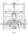
- Figure 2 is a view taken along the line 2-2 of Figure 1, showing a transverse elevation of the press bending station of in the lehr arrangement shown in Figure 1 which incorporates the novel features of the present invention and includes an outline mold, a lower pressing mold depicted in its lowered position, and an upper ring mold.
- Figure 3 is a view of the upper mold of the present invention along line 3-3 of Figure 2, illustrating the upper ring mold and pressure chamber.
- Figure 4 is an enlarged view of a portion of the ring mold showing a glass sheet pressed between the upper ring mold and the lower full surface mold.
- Figure 5 is a view similar to Figure 4 showing the pressing of a glass sheet with a lower mold that extends beyond the glass sheet perimeter.
- the present invention relates to shaping bent softened glass sheets and in particular to simultaneous shaping of doublets for a windshield but it is understood that the invention may be used to shape any number of sheets of any heat softenable sheet material where it is desired that the sheet be precisely and accurately shaped and marking of the sheet due to shaping be minimized.
- FIGS 1a and 1b depict a heating, shaping and annealing lehr for shaping glass sheets according to the present invention.
- the lehr begins upstream at a loading zone 20 and includes a heating bone 22 of tunnel type configuration, a gravity bending zone 24 downstream of the heating zone 22, a press bending or shaping station 26 immediately beyond the gravity bending zone 24, an annealing zone 28 which may include a door 30 beyond the shaping station 26, and a cooling zone 32 in end to end relation in a downstream portion of the lehr.
- An unloading zone 34 is beyond the cooling zone 32.
- a conveyor comprised of a plurality of pairs of stub rolls 36 disposed in transversely opposing longitudinally spaced relation, extends the entire length of the lehr and defines a path of movement along a longitudinal reference line.
- Each stub roll 36 is mounted on a shaft that extends through a side wall of the lehr and is connected to a conveyor drive (not shown).
- a mold return conveyor (not shown) extends along the entire lehr.
- the conveyor may be divided into a number of sections, driven from its own drive means through conventional drive rod and gear means or chain drives or the conveyor sections may be driven from a common drive through clutches in a manner well known in the art.
- a plurality of mold support carriages 38 (one only shown in Figure 2), similar to the support carriage taught in US-A-4,756,735 to Cathers et al., are conveyed along the conveyor by rotational engagement of the stub rolls 36 with a pair of longitudinally extending support rails 40 at each end of the carriage 38.
- Uprights 42 connect the rails 40 to a pair of upper longitudinal rails 44.
- a pair of upper transverse rails 46 interconnect the upper longitudinal rails 44 of the carriage 38.
- One upright 42 along each longitudinal side edge of the carriage 38 is provided with an apertured plate 48.
- the apertures in the plates 48 are arranged to be aligned between a signal transmitting device 50, such as a laser, and a signal receiving device 52, such as a photoelectric cell, both of which arc positioned along opposing sidewalls of the lehr, whenever the carriage 38 is orientated aligned and positioned correctly within the press bending station 26.
- a signal transmitting device 50 such as a laser
- a signal receiving device 52 such as a photoelectric cell
- the mold 56 includes shaping rail member 60 having a supporting surface 62 that conforms in elevation and outline to the longitudinal and transverse elevational shape desired for a glass sheet G to be bent, slightly inboard of the glass sheet perimeter.
- the mold 56 illustrated in Figure 2 may be an articulating shaping mold similar to that disclosed in US-A-4,597,789 to Reese, and includes a stationary central portion 64 and a pair of opposed, pivoting end mold wing sections 66.
- the outline mold 56 is positioned relative to the carriage 38 so that the mold's geometric center is aligned with the predetermined, vertical axis when the outline mold 56 occupies an operating position at the press bending station 26, as will be discussed later.
- the press bending station 26 comprises a lower pressing mold 68 that includes an upper press face 70 whose surface covers a continuous area corresponding to the final curved shape of a major portion of the glass sheets.
- the press face 70 which is shown to be a ceramic surface may be any type of high temperature resistant material, such as steel, and is provided with a flexible fabric material cover 72 that does not mar a hot sheet, e.g., fiber glass cloth.
- the lower mold 68 is preferable positioned on a frame 74 with its geometric center along a fixed vertical axis that coincides with the geometric center of the press bending station 26.
- a lower piston 76 which is adapted to move vertically parallel to the vertical axis at the geometric center of the press face 70 of the lower pressing mold 68, is connected to the frame 74 to raise and lover the lower pressing mold 68 in a vertical direction.
- the geometric center of the press face 70 moves along the fixed vertical axis at the geometric center at the press bending station 26.
- the press bending station 26 also includes an upper press bending mold 78 comprising a peripheral pressing ring 80 that defines a downwardly facing shaping surface 82 about the periphery of the glass sheet G to be shaped that complements the underlying upwardly facing shaping surface defined by the peripheral position of the ceramic press face 70 of the lower pressing mold 68.
- the upper pressing mold 78 is supported in a position, such that its geometric center intersects the vertical axis of movement for the geometric center of the press face 70 of the lower pressing mold 68, so that the downwardly facing shaping surface 82 defined by the press ring 80 is orientated and aligned over the upwardly facing shaping surface defined by press face 70.
- Ring 80 is supported from rigid plate 84 by web member 86, forming a plenum 88 within upper mold 78 as will be discussed later.
- Plate 84 is mounted on cylinder 90 which is supported from beam 92 of overhead frame 94. Screw jacks 96 at opposing ends of beam 92 vertically position and level ring 80 relative to the lower mold 68 and outline mold 56.
- slide 98 is positioned within cylinder 90 and is secured to piston 100 which vertically reciprocates the slide 98.
- piston 100 withdraws its arm 102, slide 98 moves upward within cylinder 90, drawing preheated fluide, and in particular, ambient temperature air from within the lehr, into chamber 104 of the cylinder 90 through opening 106 of the plate 84.
- slide 98 moves downward within cylinder 90, expelling the air, as will be discussed later.
- Ring 80 preferably extends beyond the peripheral edge of the glass sheet G as shown in Figure 4.
- the width of ring 80 is preferably wide enough to press the glass sheet G out to its peripheral edge while also the plenum 88 is sealed by a firm contact between the upper surface of the glass edge and surface 82. In this fashion, the physical contact between the upper surface of glass sheet G and press ring 80 is minimized.
- ring 80 width may be extended inwardly to press selected portions of the glass sheet G in the vicinity of the peripheral edge between complimenting upper and lower pressing surfaces.
- a mold cover (not shown) of a material similar to that provided for the lower pressing mold 68 also be provided for the pressing surface 82 of the pressing ring 80.
- a slide door 108 ( Figure 1a).
- Lifting and lowering means 110 is provided to open and close the slide door 108 when access to the press bending station 26 is needed.
- the operating sequence for the bending lehr as described earlier is similar to that disclosed in U.S. Patent No. 4,290,796.
- a pair of glass sheets of curved outline and with suitable parting material therebetween is positioned in a substantially horizontal orientation on the outline mold 56 of the mold supporting carriage 38 at the loading zone 20.
- the carriage 38 is transversely aligned relative to a longitudinal reference line through the lehr by positioning the rails 40 on the stub rolls 36.
- the carriage 38 passes through the heating zone 22 of the lehr where heating elements are arranged to provide a pattern of heating both longitudinally and transversely of the path of travel for the glass supporting mold 56 through the lehr.
- the glass sheets have been heated to their deformation temperature between 577°C to 607°C (1070°F and 1125°F) and sag to a preliminary configuration.
- end sections 66 rotate upward to further shape the glass sheets.
- the outline mold 56 may lose its approximately proper alignment in orientation with respect to the longitudinal reference line.
- the glass sheets have non-rectangular outlines of nonconform curvature in plan and are bent to complicated shapes, it is essential that the shapes be oriented and aligned exactly when they arrive at the press bending station 26. It is also important that the outline mold 56 be properly aligned above the lover pressing mold 68 to avoid mold damage.
- the apertured plates 48 mounted on the carriage 38 intercept the laser beam when the carriage 38 is improperly placed or misorientated at the press bending station 26 to stop further operation until the apertures in both plates 48 are in the path of the laser beam.
- the support carriage 38 with the mold 56 positioned thereon is repositioned to align the geometric center of the mold 56 and glass sheet G between molds 68 and 78 by an alignment device 112, such as for example that taught in US-A-4,290,796 to Reese et al..
- the pressing molds 68 and 78 are maintained at a designated elevated temperature in the press bending station 26. Elevated mold temperatures enhance the ability of the pressing molds to complete the shaping of the glass and reduce the likelihood of chill cracking in the glass, a phenomenon associated with colder molds.
- the pressing molds are at an elevated temperature that approximates the ambient temperature in the press bending station 26.
- lower piston 76 moves the lower pressing mold 68 to lift the glass sheet off the outline mold 56 and support the glass sheet during their engagement with the upper pressing mold 78.
- piston 100 retracts arm 102 so that slide 98 draws ambient temperature air into chamber 104. Mold 68 then presses glass sheets G against upper ring 88 to press the periphery of the glass sheets to the desired configuration and to form a seal about the glass sheets' peripheral edge.
- piston 100 extends arm 102, compressing the air within chamber 104 and plenum 88 to urge those portions of the glass sheet G not contacted by the ring 80 against the press face 70 of the lower press 68.
- the glass sheet G conforms to the contour of the press face 70 while not physically contacting the major portion of the glass sheets' upwardly facing major surface and marking of the upper glass surface in the central portion of the glass sheet G is eliminated.
- the amount of pressure within chamber 104 and plenum 88 is controlled by the stroke of cylinder 100.
- a timer (not shown) is actuated to hold the pressing molds in position and maintain pressure within chamber 104 and plenum 88 to ensure the imposition of the desired curved configuration.
- the timer also controls the start of the return of the lover pressing mold 68 to its lover position.
- the lower pressing mold 68 moves downward with the shaped glass sheet G supported thereon.
- a relief valve (not shown) may be positioned to vent the pressurized air from plenum 88 and/or chamber 104 after shaping is complete and prior to the downward movement of cover mold 68. As the mold 68 continues downward, it redeposits the shaped glass sheets G on shaping rail 60.
- the glass sheets Once the glass sheets have been shaped in the pressing station 26, it is necessary that they retain their conforming shapes in the annealing zone 28 until cooled from within the deformation temperature range to below the strain point of the glass, which for float glass is approximately 510°C (950°F). To ensure conformance of the glass sheets to the desired shapes, it is essential that they be cooled at a slow rate of cooling to below the strain point. The maximum rate of cooling that avoids excessive permanent warpage between the glass sheet depends upon the glass sheet thickness. After annealing, the glass sheets pass into the cooling zone 32 for additional cooling.
- the reciprocating movement of slide 98 to compress the air in chamber 104 may be eliminated by using a compressed gas source (not shown) to feed gas directly into chamber 104 and/or plenum 88. If an alternate compressed gas source is used, it is preferable that the gas be heated so as to avoid any thermal shock to the glass sheets by contacting them with gas at a temperature below that which it was exposed to prior to heating.
- the present invention may also be used in conjunction with an expandable outline mold 56 as taught in US-A-4,756,735 which allows a lover press face 170 of a mold 168 to extend beyond the peripheral edge of the glass sheet G. With his type of arrangement the periphery of the glass sheets G are fully pressed its outer edge, as shown in Figure 5.
- the pressurized gas provides a generally uniform force to the heat softened glass sheet G to urge it toward press face 70 without marking its upper surface. It is obvious that addition baffles, ducts and/or pressurized air line can be incorporated into said plenum 88 to provide additional localized forces to selected portions of the glass sheet G as required.
Claims (10)
- Dispositif propre à donner une forme prédéterminée à un matériau en feuille ramolli par la chaleur, comprenant:
un premier moule (68) présentant une face de pressage à surface pleine (70), ayant une surface de mise en forme dont le profil correspond généralement à la courbure finale désirée de ladite feuille à façonner; un second moule (78); des moyens pour positionner ladite feuille à façonner entre lesdits premier et second moules (68, 78); et des moyens (74, 76) pour déplacer ledit premier moule (68) par rapport audit second moule (78) et le mettre dans une position de contact dans laquelle ladite feuille à façonner est prise entre les surfaces de mise en forme respectives (70, 82);
caractérise en ce que le second moule (78) comporte un organe périphérique de mise en forme (80) présentant une surface de mise en forme (82) qui correspond au profil final désire de la périphérie de la feuille à façonner et qui est complémentaire d'une partie correspondante de ladite surface de mise en forme dudit premier moule (68), et une chambre (88) est définie par ledit organe périphérique de mise en forme (80); et en ce que le dispositif comprend en outre des moyens (98, 100, 102) propres à appliquer, au moyen d'un fluide sous pression dans ladite chambre (88), une force sur une partie centrale de ladite feuille à façonner, pour repousser ladite feuille vers ladite face de pressage (70) du premier moule lorsque lesdits moules (68, 78) sont dans ladite position de contact. - Dispositif selon la revendication 1, dans lequel ledit fluide est un gaz, le dispositif comprenant en outre des moyens pour préchauffer ledit gas sous pression.
- Dispositif selon la revendication 2, dans lequel lesdits moyens de mise sous pression comprennent un conduit (90) en communication avec ladite chambre (88), un élément coulissant (98) disposé dans ledit conduit (90) et des moyens (100, 102) pour déplacer ledit élément coulissant (98) dans un premier sens lorsque ledit second moule (78) est écarté de ladite feuille ramollie par la chaleur, de sorte que du gaz soit aspiré dans ladite chambre (88), et dans un second sens lorsque lesdits moules (68, 78) sont dans ladite position de contact, de sorte que ledit gaz soit mis sous pression dans ladite chambre (88) afin de repousser ladite feuille à façonner contre ladite face de pressage (70) du moule inférieur.
- Dispositif selon l'une quelconque des revendications 1 à 3, dans lequel lesdits moyens de positionnement comprennent un moule de contour et de support de la feuille (56) présentant des surfaces (62, 64) de contact avec la feuille qui correspondent à la forme et au profil en élévation désires de ladite feuille en dedans du périmètre de celle-ci, et des moyens (36, 38, 58) pour placer ladite feuille et ledit moule de contour (56) entre lesdits moules supérieur (78) et inférieur (68), et dans lequel en outre lesdits moyens de déplacement (74, 76) comprennent des moyens (74, 76) pour déplacer ledit moule inférieur (68) par rapport audit moule de contour (56) de sorte que ladite face de pressage (70) dudit moule inférieur (68) écarte dudit moule de contour (56) ledit matériau en feuille ramolli par la chaleur en le soulevant, avant que lesdits moules (68, 78) ne soient amenés dans ladite position de contact.
- Dispositif selon la revendication 1, dans lequel ledit premier moule (68) est un moule inférieur et ledit second moule (78) est un moule supérieur (78).
- Procédé de mise en forme d'un matériau en feuille ramolli par la chaleur, comprenant les étapes consistant à positionner ledit matériau en feuille ramolli par la chaleur entre un premier moule (68) présentant une face de pressage à surface pleine (70) dont le profil correspond à la courbure finale désirée de ladite feuille à façonner et un second moule (78), et à prendre ladite feuille entre lesdits premier et second moules (68, 78), caractérisé par l'étape consistant à mettre sous pression un fluide dans une chambre (88) définie par une surface de mise en forme périphérique du second moule (78) correspondant à la courbure finale désirée de ladite feuille à façonner le long de sa périphérie, pour repouser vers ledit premier moule (68) les parties de ladite feuille qui ne sont pas en contact avec ledit second moule (78).
- Procédé selon la revendication 6, dans lequel l'étape de mise sous pression comprend une aspiration de gaz dans ladite chambre (88) avant ladite étape de prise de la feuille entre les moules, et la mise sous pression dudit gaz dans ladite chambre (88) pendant ladite étape de prise de la feuille entre les moules.
- Procédé selon la revendication 7, comprenant en outre l'étape consistant à chauffer ledit gaz avant ladite étape de mise sous pression.
- Procédé selon la revendication 8, dans lequel ladite étape de positionnement comprend les opérations consistant à poser ladite feuille sur un moule de contour (56) présentant des surfaces (62, 64) de contact avec la feuille dont le contour en plan correspond à la forme et au profil en élévation de ladite feuille légèrement en dedans du périmètre de celle-ci, et à placer ledit moule de contour (56) entre lesdits premier et second moules (68, 78).
- Procédé selon la revendication 9, dans lequel ladite étape de prise de la feuille entre les moules comprend l'opération consistant à déplacer ledit premier moule (68) par rapport audit moule de contour (56) de sorte que ladite face de pressage (70) passe à travers ledit moule de contour (56) pour écarter ladite feuille dudit moule de contour en la soulevant et pour la mettre en contact avec ledit second moule (78).
Applications Claiming Priority (2)
| Application Number | Priority Date | Filing Date | Title |
|---|---|---|---|
| US248679 | 1988-09-26 | ||
| US07/248,679 US4894080A (en) | 1988-09-26 | 1988-09-26 | In-lehr glass sheet press bending using pressurized gas |
Publications (3)
| Publication Number | Publication Date |
|---|---|
| EP0361263A2 EP0361263A2 (fr) | 1990-04-04 |
| EP0361263A3 EP0361263A3 (en) | 1990-10-10 |
| EP0361263B1 true EP0361263B1 (fr) | 1993-04-14 |
Family
ID=22940200
Family Applications (1)
| Application Number | Title | Priority Date | Filing Date |
|---|---|---|---|
| EP89117229A Expired - Lifetime EP0361263B1 (fr) | 1988-09-26 | 1989-09-18 | Procédé et appareil de bombage utilisant du gaz sous pression |
Country Status (4)
| Country | Link |
|---|---|
| US (1) | US4894080A (fr) |
| EP (1) | EP0361263B1 (fr) |
| CA (1) | CA1328740C (fr) |
| DE (1) | DE68905986T2 (fr) |
Families Citing this family (16)
| Publication number | Priority date | Publication date | Assignee | Title |
|---|---|---|---|---|
| EP0431895A3 (en) * | 1989-12-05 | 1991-08-21 | Nippon Sheet Glass Co. Ltd. | Method of and apparatus for bending and tempering sheet glass |
| JPH0764575B2 (ja) * | 1990-01-11 | 1995-07-12 | 日本板硝子株式会社 | 板ガラスのプレス曲げ方法及び装置 |
| EP0445672B1 (fr) * | 1990-03-01 | 1997-06-11 | Asahi Glass Company Ltd. | Procédé et appareil pour le formage par pliage d'une feuille de verre et moule de pliage utilisé pour ledit pliage |
| US5492843A (en) * | 1993-07-31 | 1996-02-20 | Semiconductor Energy Laboratory Co., Ltd. | Method of fabricating semiconductor device and method of processing substrate |
| GB9416893D0 (en) * | 1994-08-20 | 1994-10-12 | Triplex Safety Glass Co | Heating and bending glass sheets |
| US5669952A (en) | 1994-10-14 | 1997-09-23 | Ppg Industries, Inc. | Pressure forming of glass sheets |
| JPH10117815A (ja) * | 1996-08-30 | 1998-05-12 | Ykk Corp | 面ファスナー帯およびその製造方法 |
| US6076373A (en) * | 1997-06-16 | 2000-06-20 | Ppg Industries Ohio, Inc. | Apparatus and method for bending glass sheets |
| DE10105200A1 (de) * | 2001-02-06 | 2002-08-14 | Saint Gobain | Verfahren und Vorrichtung zum paarweisen Biegen von Glasscheiben |
| EP1550639A1 (fr) * | 2003-12-26 | 2005-07-06 | Asahi Glass Company, Limited | Procédé et dispositif pour le bombage de feuilles en verre |
| US7459199B2 (en) * | 2004-01-29 | 2008-12-02 | Ppg Industries Ohio, Inc. | Method of and apparatus for strengthening edges of one or more glass sheets |
| US20150232367A1 (en) * | 2014-02-18 | 2015-08-20 | Corning Incorporated | Press bending mold cloth change system and method |
| US11247931B2 (en) * | 2016-01-28 | 2022-02-15 | Saint-Gobain Glass France | Positive pressure-supported glass bending method and device suitable therefor |
| US20190263708A1 (en) * | 2016-06-07 | 2019-08-29 | Corning Incorporated | Methods for manufacturing three-dimensional laminate glass articles |
| WO2018122767A1 (fr) * | 2016-12-30 | 2018-07-05 | Agp America S.A. | Procédé et appareil de cintrage de verre fin |
| EP4051496A4 (fr) * | 2019-10-30 | 2023-11-08 | Corning Incorporated | Procédés et systèmes de cintrage à la presse de deux ou plusieurs couches de verre |
Family Cites Families (20)
| Publication number | Priority date | Publication date | Assignee | Title |
|---|---|---|---|---|
| US2131873A (en) * | 1934-07-05 | 1938-10-04 | Libbey Owens Ford Glass Co | Apparatus for bending glass |
| US2123552A (en) * | 1936-11-19 | 1938-07-12 | Rohm & Haas | Apparatus for shaping thermoplastic sheets |
| BE505637A (fr) * | 1950-09-13 | |||
| US3068672A (en) * | 1958-02-17 | 1962-12-18 | Pittsburgh Plate Glass Co | Apparatus for bending sheet glass |
| US3208839A (en) * | 1961-02-27 | 1965-09-28 | Corning Glass Works | Method of shaping a glass article |
| US3408173A (en) * | 1965-01-29 | 1968-10-29 | Libbey Owens Ford Glass Co | Method of and apparatus for bending and tempering glass sheets |
| US3582454A (en) * | 1968-11-04 | 1971-06-01 | Corning Glass Works | Glass article forming and trimming |
| US3682613A (en) * | 1970-10-15 | 1972-08-08 | Ppg Industries Inc | Apparatus for press bending glass sheets |
| US3976462A (en) * | 1975-03-10 | 1976-08-24 | Ppg Industries, Inc. | Method and apparatus for bending glass sheets |
| US4092141A (en) * | 1977-01-03 | 1978-05-30 | Ppg Industries, Inc. | Method and apparatus for handling glass sheets for shaping and cooling |
| US4260409A (en) * | 1979-11-02 | 1981-04-07 | Ppg Industries, Inc. | Attaching flexible cover to mold for shaping glass |
| US4265650A (en) * | 1979-11-02 | 1981-05-05 | Ppg Industries, Inc. | Method of bending glass sheets in unison to complicated shapes |
| US4290796A (en) * | 1979-11-02 | 1981-09-22 | Ppg Industries, Inc. | Mold alignment means for glass sheet shaping apparatus |
| US4260408A (en) * | 1979-11-02 | 1981-04-07 | Ppg Industries, Inc. | Use of speed changes during cycling of a shaping mold |
| US4272275A (en) * | 1979-11-02 | 1981-06-09 | Ppg Industries, Inc. | Aligning glass sheets on an outline mold prior to transfer to shaping mold |
| US4274858A (en) * | 1980-01-28 | 1981-06-23 | Ppg Industries, Inc. | Molds for press bending glass sheets |
| US4305746A (en) * | 1980-05-01 | 1981-12-15 | Libbey-Owens-Ford Company | Method of and apparatus for bending glass sheets |
| US4356018A (en) * | 1981-09-04 | 1982-10-26 | Mcmaster Harold | Method and apparatus for deep bending glass sheets |
| US4597789A (en) * | 1985-08-12 | 1986-07-01 | Ppg Industries, Inc. | Tungsten alloy bending mold inserts |
| US4756735A (en) * | 1987-07-24 | 1988-07-12 | Ppg Industries, Inc. | In-lehr press bending |
-
1988
- 1988-09-26 US US07/248,679 patent/US4894080A/en not_active Expired - Lifetime
-
1989
- 1989-09-18 EP EP89117229A patent/EP0361263B1/fr not_active Expired - Lifetime
- 1989-09-18 DE DE89117229T patent/DE68905986T2/de not_active Expired - Fee Related
- 1989-09-22 CA CA000612506A patent/CA1328740C/fr not_active Expired - Fee Related
Also Published As
| Publication number | Publication date |
|---|---|
| EP0361263A2 (fr) | 1990-04-04 |
| EP0361263A3 (en) | 1990-10-10 |
| DE68905986D1 (de) | 1993-05-19 |
| DE68905986T2 (de) | 1993-10-28 |
| CA1328740C (fr) | 1994-04-26 |
| US4894080A (en) | 1990-01-16 |
Similar Documents
| Publication | Publication Date | Title |
|---|---|---|
| EP0361263B1 (fr) | Procédé et appareil de bombage utilisant du gaz sous pression | |
| US7240519B2 (en) | Apparatus and method for bending glass sheets | |
| US5735922A (en) | Method of bending and tempering glass sheets | |
| EP0706978B1 (fr) | Bombage de feuilles en verre par pressage | |
| KR0165128B1 (ko) | 아래 완전표면 진공압형과 위 링 압형을 활용하는 유리판 형성 | |
| CA1287980C (fr) | Galbage nouveau genre a la presse | |
| US4662925A (en) | Horizontal press bending of heat softened glass sheets | |
| CA2220532C (fr) | Methode et appareil pour plier des feuilles de verre | |
| KR920003978B1 (ko) | 가요성 링 모울드 | |
| US4297118A (en) | Controlling overheating of vacuum mold used to shape glass sheets | |
| US5292356A (en) | Support mechanism for a glass sheet press bending mold | |
| CA1152327A (fr) | Appareil pour le formage des feuilles de verre au moyen d'un moule diformable, a depression, et methode connexe | |
| US4437872A (en) | Apparatus for bending and tempering glass sheets | |
| JPS6141854B2 (fr) | ||
| US4233049A (en) | Method and apparatus for shaping glass sheets by drop forming | |
| US4883527A (en) | Glass sheet bending and tempering apparatus | |
| EP0692460B1 (fr) | Moule d'anneau flexible pour le bombage de feuilles de verre | |
| CA1283294C (fr) | Moule-presse a surface developpee | |
| US4488893A (en) | Movable alignment stops for glass sheet shaping apparatus | |
| US4199341A (en) | Glass lift mechanism for and method of press bending glass sheets | |
| CA2058729A1 (fr) | Appareil et methode permettant de courber des feuilles de verre grace a un moule et a une presse |
Legal Events
| Date | Code | Title | Description |
|---|---|---|---|
| PUAI | Public reference made under article 153(3) epc to a published international application that has entered the european phase |
Free format text: ORIGINAL CODE: 0009012 |
|
| AK | Designated contracting states |
Kind code of ref document: A2 Designated state(s): DE FR GB IT |
|
| PUAL | Search report despatched |
Free format text: ORIGINAL CODE: 0009013 |
|
| AK | Designated contracting states |
Kind code of ref document: A3 Designated state(s): DE FR GB IT |
|
| 17P | Request for examination filed |
Effective date: 19901221 |
|
| 17Q | First examination report despatched |
Effective date: 19920127 |
|
| GRAA | (expected) grant |
Free format text: ORIGINAL CODE: 0009210 |
|
| AK | Designated contracting states |
Kind code of ref document: B1 Designated state(s): DE FR GB IT |
|
| REF | Corresponds to: |
Ref document number: 68905986 Country of ref document: DE Date of ref document: 19930519 |
|
| ITF | It: translation for a ep patent filed |
Owner name: MODIANO & ASSOCIATI S.R.L. |
|
| ET | Fr: translation filed | ||
| K2C2 | Correction of patent specification (partial reprint) published |
Effective date: 19930414 |
|
| PLBE | No opposition filed within time limit |
Free format text: ORIGINAL CODE: 0009261 |
|
| STAA | Information on the status of an ep patent application or granted ep patent |
Free format text: STATUS: NO OPPOSITION FILED WITHIN TIME LIMIT |
|
| 26N | No opposition filed | ||
| REG | Reference to a national code |
Ref country code: FR Ref legal event code: TP |
|
| REG | Reference to a national code |
Ref country code: GB Ref legal event code: 732E |
|
| REG | Reference to a national code |
Ref country code: GB Ref legal event code: IF02 |
|
| PGFP | Annual fee paid to national office [announced via postgrant information from national office to epo] |
Ref country code: DE Payment date: 20020930 Year of fee payment: 14 |
|
| PGFP | Annual fee paid to national office [announced via postgrant information from national office to epo] |
Ref country code: GB Payment date: 20030910 Year of fee payment: 15 |
|
| PGFP | Annual fee paid to national office [announced via postgrant information from national office to epo] |
Ref country code: FR Payment date: 20030918 Year of fee payment: 15 |
|
| PG25 | Lapsed in a contracting state [announced via postgrant information from national office to epo] |
Ref country code: DE Free format text: LAPSE BECAUSE OF NON-PAYMENT OF DUE FEES Effective date: 20040401 |
|
| PG25 | Lapsed in a contracting state [announced via postgrant information from national office to epo] |
Ref country code: GB Free format text: LAPSE BECAUSE OF NON-PAYMENT OF DUE FEES Effective date: 20040918 |
|
| GBPC | Gb: european patent ceased through non-payment of renewal fee |
Effective date: 20040918 |
|
| PG25 | Lapsed in a contracting state [announced via postgrant information from national office to epo] |
Ref country code: FR Free format text: LAPSE BECAUSE OF NON-PAYMENT OF DUE FEES Effective date: 20050531 |
|
| REG | Reference to a national code |
Ref country code: FR Ref legal event code: ST |
|
| PG25 | Lapsed in a contracting state [announced via postgrant information from national office to epo] |
Ref country code: IT Free format text: LAPSE BECAUSE OF NON-PAYMENT OF DUE FEES Effective date: 20050918 |