EP0360892A1 - Electronic sensor for measuring rainfall by evaluating the impact surface of single drops - Google Patents
Electronic sensor for measuring rainfall by evaluating the impact surface of single drops Download PDFInfo
- Publication number
- EP0360892A1 EP0360892A1 EP88115906A EP88115906A EP0360892A1 EP 0360892 A1 EP0360892 A1 EP 0360892A1 EP 88115906 A EP88115906 A EP 88115906A EP 88115906 A EP88115906 A EP 88115906A EP 0360892 A1 EP0360892 A1 EP 0360892A1
- Authority
- EP
- European Patent Office
- Prior art keywords
- rain
- electronic sensor
- measuring
- sensor according
- drop
- Prior art date
- Legal status (The legal status is an assumption and is not a legal conclusion. Google has not performed a legal analysis and makes no representation as to the accuracy of the status listed.)
- Withdrawn
Links
Images


Classifications
-
- G—PHYSICS
- G01—MEASURING; TESTING
- G01W—METEOROLOGY
- G01W1/00—Meteorology
- G01W1/14—Rainfall or precipitation gauges
Definitions
- the invention relates to an electronic sensor for the instantaneous detection and evaluation of rain events.
- a rain report drops yes / no
- the integral amount of precipitation millimeters of water column
- the volumes microliters
- a rain event can also be characterized in its drop size distribution (spectrum).
- the new measuring principle enables maintenance-free continuous operation of the measuring heads outdoors.
- devices which automatically determine the amount of water in the collecting vessel. You work with the help of a mechanical float or with the help of a scale (DER 77). Electronic level measurement using optical, acoustic or capacitive (SCH 77) methods is also known.
- Precipitation meters of conventional design are still very far from meeting the requirement profile for a modern, EDP-compatible sensor system (OEH 87, ZIE 87). This applies in particular to the aspect of regular maintenance, which considerably hinders the construction of large, fully automatic measuring networks.
- a measuring area with open electrodes can be provided in addition to the funnel. reports wetting with water (JüL 81, HEI 82). If such rain detectors are actually designed to be so sensitive that every single drop can be detected, then they can also be very easily disturbed by foreign objects, corrosion or microscopic growth (false-positive continuous signal).
- the object of the invention described here is to circumvent these - mostly system-related - disadvantages as far as possible by using a novel measurement method.
- the rain gauge according to the invention is said to be particularly suitable for use in large numbers (measuring networks).
- baffle 3 The area of the baffle 3 is mainly dependent on the volume of the drop (and the associated falling speed).
- the measuring surface 2 is designed as a large-area interdigital capacitor. Such a design is known in principle in thick-film technology for the construction of high-voltage capacitors (REI 86).
- a typical embodiment is e.g. in that two comb-shaped or spiral-shaped interlocking conductor structures are applied next to one another as a pair of electrodes 4 on the surface of a suitable carrier material.
- a thin, physically and chemically inert insulating layer (dielectric) is then applied to the entire surface of the pair of electrodes 4.
- dielectric a thin, physically and chemically inert insulating layer
- a direct, ie galvanic, residual conductivity between the electrodes 4 of the measuring capacitor, which are spread out over the surface, and the water hitting the measuring surface 2 must be avoided under all circumstances.
- the dielectric itself must not interact with the water; it can neither be permeable to water or water vapor.
- the construction according to the invention differs from the group of similarly constructed moisture, gas and chemical sensors.
- the electrodes 4 are provided with an electrical connection 5 to the first stage 6 of the subsequent electronics via rear bushings.
- the measuring capacitor in the initial state has a capacitance value C1, reference number 12. If a drop of water then strikes, the water covering on the impact surface causes a sudden increase 13 of the originally existing capacity to the new value C2.
- the difference in capacitance resulting from this process is ⁇ C.
- Typical values for ⁇ C are about 10 fF for small and about 10 pF for extremely large drops.
- the increase in capacity 13 shown in FIG. 2 takes place approximately within one millisecond, the subsequent rapid reduction 14 typically takes place within 10 to 100 milliseconds.
- the measuring surface 2 is always ready to detect new drop events 16, 17 when the fast return phase 14 has ended, ie after 10 to 100 milliseconds.
- a parameter is obtained from the ⁇ C jumps with a positive sign, which is primarily correlated with the size of the impact surface and secondarily with the associated drop volume.
- the transformation of the individual ⁇ C events into the respective drop volume is given here by a non-linear, stochastic assignment.
- the evaluation error associated with the non-linearity is compensated on the one hand by a special geometry of the electrodes 4 and on the other hand by a special circuit arrangement in the signal evaluation in unit 8. Details of this linearization technique are disclosed in connection with the example described later.
- the correct drop volume can be assigned to each ⁇ C jump.
- Such a volume result related to a single drop should be referred to as a drop vector.
- the evaluation essentially consists of three successive units 6, 8, 10.
- Unit 6 is an RC oscillator.
- the electrodes 4 of the measuring capacitor form the frequency-determining capacitance of this oscillator via the connection 5.
- a frequency F is available as a signal at its output 7, which converts each positive ⁇ C jump as a negative ⁇ F jump.
- all ⁇ C jumps are impressed on the oscillator frequency as equivalent ⁇ F jumps (frequency modulation).
- the subsequent unit 8 can be understood in terms of its function as a one-way FM demodulator. However, he may only answer rapid ⁇ F jumps from higher to lower frequencies with an output signal; he must not react to jumps in the opposite direction. Even slow frequency shifts - irrespective of the direction - must not be evaluated so that the course shown in FIG. 2, reference number 15, has no influence on the accuracy of the precipitation measurement.
- PLL phase-locked loop
- the basic circuitry of this technology is known (TIE 83), but it is used here in a way that has not yet been mentioned - also in relevant monographs (BES 87).
- a signal is available at the output 9 of the phase locked loop - with a suitable additional circuit (cf. FIG. 4) - which always generates a pulse chain proportional to the frequency swing in response to every negative ⁇ F jump.
- a suitable additional circuit cf. FIG. 4
- Such an output signal is shown in FIG. 2 in a simplified form with the assignment 13 to 18 and 16 to 19.
- the incoming drop vectors are therefore added up in a counter with a programmable division ratio.
- the individual vectors can be stored in a memory matrix if necessary (to build up a drop size spectrum).
- the dimension figure formed in the counter can be calibrated (in very fine gradation) to the amount of precipitation in millimeters of water.
- the correct divider can be used as part of a wet calibration of the sensor ratio can be determined.
- the integral amount of precipitation is preferably provided at the output 11 in the resolution of 1/100 mmWS and 1/5 mmWS.
- ⁇ C jumps in drop vectors can in principle also be carried out in another way.
- the variation of the primary size C e.g. After digitalization (using known methods)
- ⁇ C can be analyzed directly in microprocessors, in particular in so-called signal processors, using software.
- the processing speed requirements are very high.
- the very efficient PLL method is therefore used as the upstream signal evaluation as the preferred type of analysis. In this way, the results can be transferred much easier (slower) to any IT system.
- the statistical fluctuation is sufficiently small after a short time (averaging). For example, the remaining statistical error range when determining exactly one millimeter of precipitation on a measuring area of only 10 cm2 is already less than 5%. It is therefore of an order of magnitude acceptable for practical use even in the case of low rainfall activities.
- all of the functions mentioned, including heating (defrosting) and temperature control, are compact, robust and water pressure-resistant in an aluminum block with the dimensions 60 x 60 x 40 mm.
- Both a high-resolution signal (1/100 mm water column) and a signal standardized to 0.2 millimeter water column are provided at the output socket of the measuring head.
- the latter is compatible with the conventional rain gauge designs with a seesaw.
- the manufacturing costs of the construction according to the invention including defrosting are clearly below the level of a Hellmann funnel with a rocker.
- an aluminum oxide ceramic with a thickness of 0.6 mm and an edge length of 44 mm serves as the carrier material for the measuring surface.
- a multi-phase (programmable) conductor track structure according to FIG. 3 is applied on the front using thick-film technology.
- the measuring capacitor is divided into several individual capacitors (zones) that are independent of one another.
- the geometry shown in FIG. 3 allows the subsequent calibration (via actuators on the back or contact bridges) to determine separately for each of the six zones whether a narrow, a medium or a wide electrode spacing (mesh size) should be effective there.
- the electrode spacing has a great influence on the height and the time course of the ⁇ C jumps.
- the above-mentioned non-linearity in the conversion of ⁇ C jumps in drop processors is largely compensated for by the correct design and combination of the six different zones.
- the demodulator module 8 With correct adjustment (programming) of the compensation measure described here, the demodulator module 8 only has to compensate for a residual error with respect to the linearization.
- the surface quality of the dielectric applied to the measuring surface 2 is of particular importance both for the accuracy and for the long-term stability of the evaluation. Good results are achieved, for example, with chemically resistant glass coatings (glazes). Suitable layer thicknesses are, for example, in the order of 10 to 100 ⁇ m.
- a sensor variant is optimized in such a way that the glaze, which is fired as a dielectric, can be very easily and completely wetted with water, i.e. has a permanently hydrophilic surface. If a glaze does not show this property immediately after firing, the hydrophilicity can also be subsequently increased by etching processes or by chemically reactive modification of the glass surface (e.g. in the form of a permutite structure).
- a strongly hydrophobic surface is realized.
- Corresponding properties can e.g. by melting thin layers of silicone polymers or by a Teflon coating.
- a chemically reactive modification of the glass surface by coupling hydrolysis-stable dimethylsiloxane or octyl groups also provides useful results.
- the bottom line is that there are a number of practical alternatives for both the hydrophilic and the hydrophobic sensor variant. Depending on the application, long-term stability or budget, the most advantageous method can be selected.
- An assigned pulse width controller determines the actual temperature of the measuring surface 2 and doses the heating power so that a surface temperature of + 5 ° C is maintained in frost. With the maximum power density of 1 Wcm ⁇ 2, the defrosting is effective down to outside temperatures of - 40 ° C.
- the RC oscillator is a standard circuit.
- an integrated circuit of the CMOS series 40HC60 can be used successfully.
- a high operating frequency should be aimed for; here it is in the range from 1 to MHz.
- phase locked loop (FIG. 1, module 8) is further broken down in FIG.
- a highly integrated standard module (40HC46) contains a voltage-controlled oscillator (VCO) 20 and an edge-triggered phase comparator (PHD) 22.
- VCO voltage-controlled oscillator
- PLD edge-triggered phase comparator
- the circuit is supplemented by a divider stage 21, an exclusive-OR gate (XOR) 24, a low pass 25 and a Schmitt Trigger (ST) 26.
- XOR exclusive-OR gate
- ST Schmitt Trigger
- phase locked loop works with a correct dimensioning of the loop filter 23 with a PI behavior.
- pulse groups are passed on as a result, which are to be interpreted as drop vectors.
- the desired demodulator function and linearization can be realized in an almost ideal way (and with minimal component expenditure).
- FIG. 5 shows which different signals are obtained by further processing (FIG. 1, construction unit 10) of the drop vectors.
- the individual drop volumes are output as calibrated pulse chains for building up drop spectra.
- a positive pulse from signal E2 represents exactly 1/100 mmWS, with signal E3 it is 1/5 mmWS.
- signal E4 With signal E4, a standardized counting pulse of 100 ms is available for every drop - regardless of its size.
- Signal E5 remains at H level for exactly 10 minutes after each drop and can therefore be used as a simple rain message (yes / no).
- a particularly effective method for avoiding wind direction errors is the simultaneous use of two to four measuring surfaces of the same type, but pointing in different directions.
- the individual sectors of such a multiple arrangement could, for example, be attached to a (sloping) roof surface of a pyramid-shaped base body (Janus head).
- FIG. 6 shows the recorder log of an isolated, relatively short-term precipitation event. The duration of the event was limited to approximately seven minutes. During this time, 22 individual drops were detected, the total amount of water that was rained down was only 0.05 mm water column.
- FIG. 7 shows, by way of example, two drop size distributions (raindrop spectra), which were obtained by online evaluation of the drop vectors using a computer.
- 100 consecutive drops are classified according to their volume.
- a total of 40 size classes are shown.
- the class width is 0.2 ⁇ l each.
- the area shown in the graphic covers drop volumes of 0.2 to 8 ⁇ l.
- PRU 80 The technical literature (PRU 80) shows that the working range of the example designed according to the invention, ie from about 0.2 to 100 ⁇ l per drop, actually covers the drop volumes that dominate in practice.
- this rain sensor optimized for Central European conditions, only mist wetting at the lower end of the spectrum and tropical monsoon rain at the upper end of the spectrum can no longer be detected correctly.
- remedial action can also be taken if necessary.
Landscapes
- Life Sciences & Earth Sciences (AREA)
- Environmental & Geological Engineering (AREA)
- Hydrology & Water Resources (AREA)
- Engineering & Computer Science (AREA)
- Atmospheric Sciences (AREA)
- Biodiversity & Conservation Biology (AREA)
- Ecology (AREA)
- Environmental Sciences (AREA)
- Investigating Or Analyzing Materials By The Use Of Electric Means (AREA)
Abstract
Description
Die Erfindung bezieht sich auf einen elektronischen Sensor zur verzögerungsfreien Erkennung und Bewertung von Regen-Ereignissen. Als Ergebnis werden dabei gleichzeitig eine Regenmeldung (Tropfen Ja/Nein), die integrale Niederschlagshöhe (Millimeter Wassersäule) sowie die Volumina (Mikroliter) der einzelnen Regentropfen zur Verfügung gestellt. Mit Hilfe dieser Daten kann ein Regen-Ereignis auch in seiner Tropfengrößen-Verteilung charakterisiert werden (Spektrum). Das neuartige Meßprinzip ermöglicht wartungsfreien Dauerbetrieb der Meßköpfe im Freien.The invention relates to an electronic sensor for the instantaneous detection and evaluation of rain events. As a result, a rain report (drops yes / no), the integral amount of precipitation (millimeters of water column) and the volumes (microliters) of the individual raindrops are made available at the same time. With the help of this data, a rain event can also be characterized in its drop size distribution (spectrum). The new measuring principle enables maintenance-free continuous operation of the measuring heads outdoors.
Herkömmliche Regenmesser sammeln die Regentropfen in einem speziell geformten Trichter (Hellmann-Trichter). Eine Konstruktion dieser Art (mit einer Auffangfläche von 200 cm²) wurde bereits im Jahre 1966 mit einer Normung (DIN 58 666). Die ausfließende Wassermenge wird nach unterschiedlichen Methoden bestimmt. Im einfachsten Fall wird das Wasser in einem Sammelgefäß aufgefangen; es muß dann in regelmäßigen Abständen manuell in einen Meßzylinder überführt und abgelesen werden (DIN 58 667).Conventional rain gauges collect the raindrops in a specially shaped funnel (Hellmann funnel). A construction of this type (with a collecting area of 200 cm²) was already in 1966 with a standard (DIN 58 666). The amount of water flowing out is determined using different methods. In the simplest case, the water is collected in a collecting vessel; it must then be transferred manually into a measuring cylinder and read at regular intervals (DIN 58 667).
Als Weiterentwicklung sind Geräte bekannt, die die Wassermenge im Sammelgefäß automatisch ermitteln. Sie arbeiten mit Hilfe eines mechanischen Schwimmers oder mit Hilfe einer Waage (DER 77). Auch die elektronische Füllstandsmesung mit optischen, akustischen oder kapazitiven (SCH 77) Verfahren ist bekannt.As a further development, devices are known which automatically determine the amount of water in the collecting vessel. You work with the help of a mechanical float or with the help of a scale (DER 77). Electronic level measurement using optical, acoustic or capacitive (SCH 77) methods is also known.
In automatisierten meteorologischen Beobachtungsstationen ist es heute Stand der Technik, die ausfließende Wassermenge mit einer relativ einfachen, elektromechanischen Wippvorrichtung zu ermitteln, die im Wesentlichen auf amerikanische Patentschriften zurückgeht (KAH 72, BAE 74). Zwei gleichgroße Meßgefäße sind dicht nebeneinander auf einer speziellen Kontaktwippe angebracht. Die Wippe ist so aufgebaut, daß das zunächst stabile Gleichgewicht mit steigender Füllhöhe labil wird. Beim Erreichen einer bestimmten Füllung löst dann das schwerere Gefäß rein mechanisch einen Kippvorgang aus. Beim Kippen entleert es sich und bringt zugleich das jeweils andere Gefäß unter den Auslauf. Dadurch wird der Wasserfluß wechselweise in das Paar von Meßgefäßen aufgeteilt und dabei zugleich quantisiert. Jeder Kippvorgang wird über einen Reedkontakt o. dgl. elektrisch gemeldet.In automated meteorological observation stations, it is state of the art today to determine the amount of water flowing out using a relatively simple, electromechanical rocker device, which is essentially based on American patents (KAH 72, BAE 74). Two measuring vessels of the same size are mounted close together on a special contact rocker. The rocker is constructed so that the initially stable equilibrium becomes unstable with increasing fill level. When a certain filling is reached, the heavier vessel triggers a tipping process purely mechanically. When tipped, it empties and at the same time brings the other vessel under the spout. This will make the water flow alternately divided into the pair of measuring vessels and at the same time quantized. Each tilting process is reported electrically via a reed contact or the like.
Alle bisher genannten Konstruktionen zeigen bei Dauerbetrieb im Freien eine Reihe von gravierenden Nachteilen:
- A) Benetzungsfehler: Bei einsetzendem Regen muß zunächst die gesamte Oberfläche des Auffangtrichters mit Regenwasser benetzt sein, bevor der erste Tropfen zur Auswertung gelangen kann. Durch diese Benetzung entstehen regelmäßig Wasserverluste. Bei der isolierten Auswertung kurzfristiger Regenereignisse führen diese Verluste zu erheblicher Unterbewertung.
- B) Verdunstungsfehler: Unabhängig von den erwähnten Benetzungsverlusten entsteht ein permanenter Wasserverlust durch Verdunstung. Auch diese Fehlerquelle kann bei schwachem Regen erheblich sein.
- C) Zeitfehler: Wegen der Benetzung entsteht die Information über den Beginn eines Regenereignisses immer mit einer mehr oder minder großen Zeitverzögerung. Diese ist bei vielen Anwendungen unerwünscht. Beispielsweise dort, wo die Regen-Information zeitgleich mit Analysenwerten aus der Luftüberwachung (Staub, SOx, NOx, Radioaktivität etc.) aufgezeichnet wird, um Auswaschungs-Effekte zu erkennen. Besonders kritisch ist die Zeitverzögerung bei der Erzeugung von Warn-Hinweisen bezüglich des Zustands von Landebahnen, Autoschnellstraßen etc.
- D) Linearitätsfehler: Bei starkem Regen kippt die Wippe zu früh. Dies hängt zum Teil mit der kinetischen Energie des auslaufenden Wasserstrahls zusammen. Die Wippe erzeugt dann in diesen Perioden eine Falschbewertung, die allein mit 3 bis 4 % beziffert wird (NEL 83).
- E) Geringe Auflösung: Mit einem Fassungsvermögen von ca. 10 ml erzeugt eine Wippe herkömmlicher Bauart etwa fünf Kippvorgänge pro Millimeter Wassersäule. Mit einer solchen Auflösung lassen sich geringe Niederschlagsaktivitäten - die in regenarmen Gebieten der Erde von großen Bedeutung sein können - nur ungenau erfassen. F) Frendkörperprobleme: Dort, wo das Wasser vom Trichter in den relativ engen Auslaßstutzen geführt wird, besteht immer die Gefahr, daß entweder der düsenförmige Auslaß oder das vorgelagerte Sieb durch Flugsand, Blütenblätter, Samen, Vogelfedern etc. verstopft. Auch Störungen des Wippenmechanismus duch Insekten, sowie biologische Ablagerungen in den Meßgefäßen, können die Meßgenauigkeit beeinträchtigen. Ein sicherer Betrieb der herkömmlichen Regenmesser ist nur bei regelmäßiger (möglichst täglicher) Inspektion gewährleistet. Der Aufstellungsort muß daher frei zugänglich bleiben; eine Dach- oder Mastmontage scheidet praktisch aus.
- G) Aufwendiger Frostschutz: Wenn die Niederschlagsmessung auch bei Minustemperaturen korrekt arbeiten soll, muß der gesamte Auffangtrichter per Thermostat über dem Gefrierpunkt gehalten werden. Bei der großen Fläche des Trichters müssen hierzu beträchtliche Heizleistungen bereitgehalten werden. Dies führt insbesondere bei batterie- oder solarbetriebenen Außenstationen zu erheblichen Versorgungsproblemen.
- H) Erschütterungs- und Neigungsempfindlichkeit: Konstruktionsbedingt muß ein mit Wippe ausgestatteter Regenmesser immer erschütterungsfrei und genau waagrecht aufgestellt werden. Dies verhindert beispielsweise den Einsatz solcher Geräte auf Schiffen, Wetterbojen oder an mobilen Meßfahrzeugen (Katastrophenschutz). Auch der ortsfeste Betrieb an exponierter Stelle kann problematisch werden, wenn die Tragekonstruktion bei starkem Wind vibriert oder sonstige Bewegungen ausführt.
- A) Wetting error: When rain starts, the entire surface of the collecting funnel must be wetted with rain water before the first drop can be evaluated. This wetting regularly results in water losses. In the isolated evaluation of short-term rain events, these losses lead to considerable undervaluation.
- B) Evaporation errors: Irrespective of the wetting losses mentioned, there is permanent water loss due to evaporation. This source of error can also be significant in light rain.
- C) Time error: Because of the wetting, the information about the start of a rain event always arises with a more or less great time delay. This is undesirable in many applications. For example, where the rain information is recorded at the same time as analysis values from air monitoring (dust, SO x , NO x , radioactivity, etc.) in order to identify washout effects. The time delay in the generation of warnings regarding the condition of runways, expressways, etc. is particularly critical.
- D) Linearity error: The rocker tilts too early in heavy rain. This is partly due to the kinetic energy of the emerging water jet. The seesaw then generates an incorrect evaluation in these periods, which is estimated at 3 to 4% alone (NEL 83).
- E) Low resolution: With a capacity of approx. 10 ml, a rocker of conventional design generates about five tipping processes per millimeter of water. With such a resolution, low precipitation activities - which can be of great importance in low-rain regions of the world - can only be recorded inaccurately. F) Foreign body problems: Where the water is led from the funnel into the relatively narrow outlet connection, there is always the risk that either the nozzle-shaped outlet or the upstream sieve will be blocked by flying sand, petals, seeds, bird feathers etc. Faults in the seesaw mechanism caused by insects, as well as biological deposits in the measuring vessels, can impair the measuring accuracy. Safe operation of conventional rain gauges is only guaranteed if they are inspected regularly (if possible daily). The installation site must therefore remain freely accessible; a roof or mast installation is practically out of the question.
- G) Complex frost protection: If the precipitation measurement is to work correctly even at sub-zero temperatures, the entire collecting funnel must be kept above freezing point by means of a thermostat. Given the large area of the funnel, considerable heating power must be kept ready for this. This leads to considerable supply problems, particularly in the case of battery or solar-operated outstations.
- H) Vibration and inclination sensitivity: Due to the design, a rain gauge equipped with a rocker must always be set up vibration-free and exactly horizontal. This prevents, for example, the use of such devices on ships, weather buoys or on mobile measuring vehicles (disaster protection). Fixed operation at an exposed location can also be problematic if the support structure vibrates in strong winds or makes other movements.
Zusammenfassend ergibt sich, daß von den bisher bekannten Regenmessern nur eine begrenzte Genauigkeit erwartet werden kann. Der Deutsche Wetterdienst beispielsweise benennt für seine Niederschlagsstationen systematisch bedingte Fehlerbeträge - je nach Jahreszeit - zwischen 16% und 40% für die langfristige Beobachtung (KEL 79). Bei kurzfristiger Beobachtung ist eine wesentlich höhere Fehlerbreite anzusetzen.In summary, it can be seen that only a limited accuracy can be expected from the previously known rain gauges. The German Meteorological Service, for example, specifies systematic error amounts for its precipitation stations - depending on the season - between 16% and 40% for long-term observation (KEL 79). In the case of short-term observation, a much larger range of errors is to be set.
Niederschlagsmesser herkömmlicher Bauart sind auch noch sehr weit davon entfernt, dem Anforderungsprofil an eine moderne, EDV-kompatible Sensorik zu entsprechen (OEH 87, ZIE 87). Dies gilt insbesondere für den Aspekt der regelmäßigen Wartung, die den Aufbau großer, vollautomatischer Meßnetze erheblich behindert.Precipitation meters of conventional design are still very far from meeting the requirement profile for a modern, EDP-compatible sensor system (OEH 87, ZIE 87). This applies in particular to the aspect of regular maintenance, which considerably hinders the construction of large, fully automatic measuring networks.
Einige der beschriebenen Schwachpunkte können durch Modifikationen und Ergänzungen aufgebessert werden. Eine wichtige Ergänzung zum Trichter/Wippe-Konzept wurde in den siebziger Jahren vom Deutschen Wetterdienst (Meteorologisches Observatorium Hohenpeißenberg) entwickelt und in der Praxis eingeführt: der sogenannte Tropfer, auch Ombrometer(R) genannt. Hier wird zwischen dem Auffangtrichter und der Wippe eine Lichtschranke eingefügt, die dann bereits im Vorlauf einzelne Tropfen erkennen und abzählen kann.Some of the weaknesses described can be improved by modifications and additions. An important addition to the funnel / seesaw concept was developed and put into practice by the German Weather Service (Hohenpeißenberg Meteorological Observatory) in the 1970s: the so-called dropper, also known as an ombrometer (R) . Here, a light barrier is inserted between the collecting funnel and the rocker, which can then recognize and count individual drops in advance.
Als eine neuere Variante des zuletzt beschriebenen Verfahrens kann die Tropfenzählung mit Hilfe einer Gleichstrom-Leitwertmessung (an einer Draht-Matrix) angesehen werden (NEL 83). Mit beiden Varianten der Tropfenzählung kann zwar der unter E) genannte Nachteil vermieden werden, die Punkte D), F) und H) werden jedoch noch kritischer.As a newer variant of the method described last, the drop counting can be viewed with the help of a DC conductance measurement (on a wire matrix) (NEL 83). With both variants of drop counting, the disadvantage mentioned under E) can be avoided, but points D), F) and H) become even more critical.
Dort, wo eine sehr schnelle Ja/Nein-Entscheidung in Bezug auf Regen notwendig ist, kann neben dem Trichter zusätzlich eine Meßfläche mit offenen Elektroden vorgesehen werden, die durch Leitfähigkeitsmessung o.ä. eine Benetzung mit Wasser meldet (JüL 81, HEI 82). Wenn solche Regenmelder tatsächlich so empfindlich ausgelegt werden, daß jeder einzelne Tropfen detektierbar ist, dann können sie auch sehr leicht durch anfliegende Fremdkörper, Korrosion oder Mikoben-Bewuchs gestört werden (falsch-positives Dauersignal).Wherever a very quick yes / no decision is necessary with regard to rain, a measuring area with open electrodes can be provided in addition to the funnel. reports wetting with water (JüL 81, HEI 82). If such rain detectors are actually designed to be so sensitive that every single drop can be detected, then they can also be very easily disturbed by foreign objects, corrosion or microscopic growth (false-positive continuous signal).
Die in der Fachwelt hinreichend bekannten Nachteile haben in der Vergangenheit auch dazu geführt, daß vielfältige Versuche unternommen worden sind, die Genauigkeit und die Zuverlässigkeit der Regenmessung durch die Anwendung vollkommen neuartiger Meßprinzipien zu verbessern.The disadvantages well known in the art have also led in the past to the fact that various attempts have been made to improve the accuracy and the reliability of the rain measurement by using completely new measuring principles.
Ein solcher Versuch ist die Wassermengenbestimmung durch Impedanzmessung an einem Füllkörper (WAL 85). Feldversuche mit der vorgeschlagenen Anordnung sind in der Literatur bisher nicht dokumentiert. Bei genauem Studium des Prinzips ist jedoch offenkundig, daß die Mehrzahl der oben unter A) bis H) genannten Schwachpunkte auch für diese Anordnung zutreffen muß.One such attempt is the determination of the amount of water by impedance measurement on a packing (WAL 85). So far, field tests with the proposed arrangement have not been documented in the literature. If the principle is carefully studied, however, it is obvious that the majority of the weaknesses mentioned under A) to H) above must also apply to this arrangement.
Eine wirklich nennenswerte Verbesserung des Standes der Technik ist bisher nur mit extrem aufwendigen Methoden auf optischer Basis (Laser) oder mit Hilfe der Radartechnik gelungen. Solche (naturgemäß sehr kostspieligen) Großgeräte konnten nur vereinzelt in wissenschaftlichen Studien eingesetzt werden. Sie sind insbesondere keine in Stückzahlen einsetzbare Alternative für meteorogogische Meßnetze. Eine gute übersicht über alle bisher bekannten Sonderverfahren ist in einer diesbezüglichen Patentschrift zu finden (HAN 86).A really noteworthy improvement in the state of the art has so far only been possible with extremely complex methods on an optical basis (laser) or with the help of radar technology. Such (naturally very expensive) Large devices could only be used occasionally in scientific studies. In particular, they are not an alternative for meteorological measurement networks that can be used in quantities. A good overview of all previously known special processes can be found in a related patent specification (HAN 86).
Mit Ausnahme der (hier nicht relevanten) Sonderverfahren verbleiben bei der Regenmessung nach dem Stand der Technik heute immer noch die Mehrzahl der oben unter A) bis H) aufgeführten Problembereiche. Aufgabe der hier beschriebenen Erfindung ist es, diese - meist systembedingten - Nachteile durch Anwendung eines neuartigen Meßverfahrens so weit wie Möglich zu umgehen. Der erfindungsgemäße Regenmesser soll sich insbesondere für den Einsatz in großen Stückzahlen (Meßnetze) eignen.With the exception of the special procedures (not relevant here), the majority of the problem areas listed above under A) to H) still remain with the rain measurement according to the prior art. The object of the invention described here is to circumvent these - mostly system-related - disadvantages as far as possible by using a novel measurement method. The rain gauge according to the invention is said to be particularly suitable for use in large numbers (measuring networks).
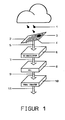
Zunächst soll anhand des Blockschemas von Figur 1 und des Signalverlaufs von Figur 2 eine übersicht über das zugrundeliegende Prinzip des erfindungsgemäßen Regensensors gegeben werden: Der Sensor arbeitet mit Hilfe einer Meßfläche 2, die direkt dem Regen ausgesetzt ist. Die Regentropfen 1 fallen unmittelbar auf diese Fläche und erzeugen dort beim Aufprall (kurzfristig) einen deutlich abgegrenzten, runden Wasserfleck. Dieser Fleck soll im Folgenden als Prallfläche 3 bezeichnet werden. Das Areal der Prallfläche 3 ist hauptsächlich vom Volumen des Tropfens (und der zugehörigen Fallgeschwindigkeit) abhängig.First of all, an overview of the underlying principle of the rain sensor according to the invention is to be given on the basis of the block diagram of FIG. 1 and the signal curve of FIG. The
Die Meßfläche 2 ist als ein großflächiger Interdigital-Kondensator ausgebildet. Eine solche Bauart ist in der Dickschicht-Technologie vom Prinzip her zum Aufbau von Hochspannungs-Kondensatoren bekannt (REI 86). Eine typische Ausführungsform besteht z.B. darin, daß auf der Oberfläche eines geeigneten Trägermaterials zwei kammförmig oder spiralförmig ineinandergreifende Leiterstrukturen nebeneinander als Elektrodenpaar 4 aufgebracht sind.The measuring
Auf dem Elektrodenpaar 4 ist dann flächendeckend eine dünne, physikalisch und chemisch inerte Isolierschicht (Dielektrikum) angebracht. Eine direkte d.h. galvanische Restleitfähigkeit zwischen den flächenhaft ausgebreiteten Elektroden 4 des Meßkondensators und dem auf der Meßfläche 2 auftreffenden Wasser muß unter allen Umständen vermieden werden. Das Dielektrikum selbst darf auch keinerlei Wechselwirkung mit dem Wasser eingehen; es darf weder für Wasser noch für Wasserdampf durchlässig sein. Anhand der in diesem Abschnitt genannten Merkmale unterscheidet sich die erfindungsgemäße Konstruktion von der Gruppe ähnlich aufgebauter Feuchte-, Gas- und Chemosensoren. über rückseitige Durchführungen erhalten die Elektroden 4 einen elektrischen Anschluß 5 an die erste Stufe 6 der nachfolgenden Elektronik.A thin, physically and chemically inert insulating layer (dielectric) is then applied to the entire surface of the pair of
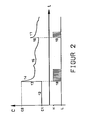
Zunächst sollen die hydrodynamischen Vorgänge während des Auftreffens eines Wassertropfens betrachtet und deren Auswirkung auf die Meßfläche beschrieben werden: Gemäß Figur 2 hat der Meßkondensator im Ausgangszustand einen Kapazitätswert C1, Bezugszeichen 12 . Wenn dann ein Wassertropfen auftrifft, so bewirkt die Wasserbedeckung auf der Prallfläche eine sprunghafte Erhöhung 13 der ursprünglich vorhandenen Kapazität auf den neuen Wert C2. Der bei diesem Vorgang enstehende Unterschied in der Kapazität sei ΔC. Typische Werte für ΔC betragen etwa 10 fF für kleine und etwa 10 pF für extrem große Tropfen. Der in Figur 2 gezeigt Kapazitätsanstieg 13 läuft etwa innerhalb einer Millisekunde ab, der darauf folgende schnelle Abbau 14 typischerweise innerhalb von 10 bis 100 Millisekunden.First of all, the hydrodynamic processes during the impact of a drop of water should be considered and their effect on the measuring surface should be described: According to FIG. 2, the measuring capacitor in the initial state has a capacitance value C1,
Mit Hilfe einer definierten Schrägstellung der Meßfläche 2 und verstärkt durch eine spezielle Oberflächenbehandlung wird nun dafür gesorgt, daß die in der Prallfläche 3 vorhandene Wassermenge innerhalb kurzer Zeit von den sensiblen Partien der meßfläche abläuft. Für die Dauer des Ablaufvorgangs stellt sich gewöhnlich für etwa 1000 Millisekunden ein Kapazitätsverlauf mit undefinierten Schwankungen 15 ein. die genannte Schrägstellung erschwert zugleich die Anhaftung von Fremdkörpern aller Art auf der Meßfläche 2. Es ist vorteilhaft, die Meßfläche 2 so in das Sensorgehäuse zu integrieren, daß jeglicher Schmutz an der Unterkante (Figur 1: links) frei abgleiten kann. Dies unterstützt den Selbstreinigungs-Effekt der Meßfläche.With the help of a defined inclination of the measuring
Vom Prinzip her ist die Meßfläche 2 immer dann wieder zur Erfassung neuer Tropfen-Ereignisse 16, 17 bereit, wenn die schnelle Rücklaufphase 14 beendet ist, d.h. nach 10 bis 100 Millisekunden. Dadurch, daß die nachgeordnete Signalauswertung 6, 8, 10 in der Lage ist, ausschließlich auf sehr schnelle Erhöhungen der Kapazität (ΔC-Sprünge mit positvem Vorzeichen) zu reagieren, ist es für die Genauigkeit der nächstfolgenden Tropfenbewertung 16, 17 unerheblich, ob das ursprüngliche Kapazitätsniveau 12 wieder erreicht worden ist oder nicht. Auch dauerhafte Niveauver schiebungen durch Temperaturdrift oder durch Anhaften kleinerer Fremdkörper auf der Meßfläche 2 (Verschmutzung), würden die Erkennung und korrekte Bewertung neuer Tropfen nicht behindern.In principle, the measuring
Erfindungsgemäß wird aus den ΔC-Sprüngen mit positivem Vorzeichen ein Parameter gewonnen, der primär mit der Größe der Prallfläche und sekundär auch mit dem zugehörigen Tropfenvolumen korreliert ist. Die Transformation der einzelnen ΔC-Ereignisse in das jeweilige Tropfenvolumen ist hier durch eine nicht-lineare, stochastische Zuordnung gegeben. Der mit der Nicht-Linearität zusammenhängende Bewertungsfehler wird einerseits durch eine besondere Geometrie der Elektroden 4 und andererseits durch eine spezielle Schaltungsanordnung bei der Signalauswertung in Einheit 8 kompensiert. Im Zusammenhang mit dem später beschriebenen Beispiel werden Details dieser Linearisierungstechnik offenbart.According to the invention, a parameter is obtained from the ΔC jumps with a positive sign, which is primarily correlated with the size of the impact surface and secondarily with the associated drop volume. The transformation of the individual ΔC events into the respective drop volume is given here by a non-linear, stochastic assignment. The evaluation error associated with the non-linearity is compensated on the one hand by a special geometry of the
Nach erfolgter Linearisierung kann jedem ΔC-Sprung das korrekte Tropfenvolumen zugeordnet werden. Ein solches, auf einen einzelnen Tropfen bezogenes Volumen-Ergebnis soll als Tropfenvektor bezeichnet werden.After linearization, the correct drop volume can be assigned to each ΔC jump. Such a volume result related to a single drop should be referred to as a drop vector.
Wesentlich an dem erfindungsgemäßen Verfahren ist die Tatsache, daß die Dynamik des Primärsignals ausgewertet wird. Das der Erfindung zugrundeliegenden Prinzips kann daher im englischen Sprachgebrauch sehr treffend mit dem Begriff "Electronic Impact Sizing = ELIS" charakterisiert werden.What is essential to the method according to the invention is the fact that the dynamics of the primary signal are evaluated. The principle on which the invention is based can therefore be aptly characterized in English using the term "electronic impact sizing = ELIS".
Als Nächstes soll die Arbeitsweise der erfindungsgemäßen Signalauswertung unter Bezug auf die in Figur 1 dargestellten Blöcke näher erläutert werden. Die Auswertung besteht im Wesentlichen aus drei aufeinanderfolgenden Einheiten 6, 8, 10 . Einheit 6 ist ein RC-Oszillator. Die Elektroden 4 des Meßkondensators bilden über den Anschluß 5 die Frequenzbestimmende Kapazität dieses Oszillators. An seinem Ausgang 7 steht als Signal eine Frequenz F zur Verfügung, die jeden positiven ΔC-Sprung als negativen ΔF-Sprung umsetzt. Faktisch werden der Oszillatorfrequenz alle ΔC-Sprünge als äquivalente ΔF-Sprünge aufgeprägt (Frequenzmodulation).Next, the operation of the signal evaluation according to the invention will be explained in more detail with reference to the blocks shown in FIG. 1. The evaluation essentially consists of three
Die nachfolgende Einheit 8 kann von ihrer Funktion her als einseitig wirkender FM-Demodulator aufgefaßt werden. Er darf allerdings nur schnelle ΔF-Sprünge von höheren nach tieferen Frequenzen mit einem Ausgangssignal beantworten; auf Sprünge in umgekehrter Richtung darf er nicht reagieren. Auch langsame Frequenzverschiebungen - gleichgültig in welcher Richtung - dürfen nicht ausgewertet werden, damit der in Figur 2, Bezugszeichen 15 dargestellte Verlauf ohne Einfluß auf die Genauigkeit der Niederschlagsmessung bleibt.The
Besonders vorteilhaft für die weitere Aufbereitung des Signals ist die Ausgestaltung des FM-Demodulators 8 in den Techniken eines Phasenregelkreises, auch Nachlaufsychronisation genannt (engl.: Phase-Locked Loop, PLL). Die Grundschaltung dieser Technik ist bekannt (TIE 83), sie wird jedoch hier in einer Art und Weise eingesetzt, wie sie bisher - auch in einschlägigen Monografien (BES 87) - noch nicht erwähnt ist.The configuration of the
Innerhalb der erfindungsgemäßen Anordnung steht am Ausgang 9 des Phasenregelkreises - bei geeigneter Zusatzbeschaltung (vergl. Figur 4) - ein Signal zur Verfügung, das als Antwort auf jeden negativen ΔF-Sprung immer eine dem Frequenzhub proportionale Impulskette (engl.: Burst) erzeugt. Ein solches Ausgangsignal ist in Figur 2 mit der Zuordnung 13 zu 18 und 16 zu 19 in vereinfachter Form dargestellt.Within the arrangement according to the invention, a signal is available at the
Wesentlich für die Exaktheit der Umsetzung von ΔF-Sprüngen in die zugehörigen Tropfenvektoren ist hier, daß mit Hilfe der erfindungsgemäß erzeugten Krümmung in der Kennlinie des PLL-Demodulators auch die oben erwähnte Nicht-Linearität auskorrigiert wird. Erst nach dieser Korrekturmaßnahme kann die Anzahl der Flanken (18, 19) aus dem Phasenregelkreis direkt als Tropfenvektor ausgegeben werden. An dieser Stelle sei daran erinnert, daß die hier beschriebene, elektronische Korrekturmaßnahme in Verbindung mit den geometrischen Korrekturmaßnamen an der Meßfläche gesehen werden muß.It is essential for the accuracy of the conversion of ΔF jumps into the associated drop vectors that the above-mentioned non-linearity is also corrected with the aid of the curvature generated according to the invention in the characteristic curve of the PLL demodulator. Only after this correction measure can the number of edges (18, 19) from the phase locked loop be output directly as a drop vector. At this point it should be remembered that the electronic correction measure described here must be seen in connection with the geometric correction measures on the measuring surface.
Durch Summation der zeitlich aufeinanderfolgenden Vektoren ergibt sich ein genaues Maß für die auf Meßfläche 2 auftreffende Wassermenge. In der letzten Stufe 10 werden daher die einlaufenden Tropfenvektoren in einem Zähler mit programmierbarem Teilerverhältnis aufaddiert. Darüber hinaus können die einzelnen Vektoren bei Bedarf (zum Aufbau eines Tropfengrößen-Spektrums) in einer Speichermatrix abgelegt werden.By summing the chronologically successive vectors, an exact measure of the amount of water impinging on measuring
Die in dem Zähler gebildete Maßzahl läßt sich (in sehr feiner Abstufung) auf die Niederschlagshöhe in Millimetern Wassersäule kalibrieren. Im Rahmen einer nassen Kalibrierung des Sensors kann das korrekte Teiler verhältnis ermittelt werden. Vorzugsweise wird die integrale Niederschlagshöhe in der Auflösung von1/100 mmWS und 1/5 mmWS am Ausgang 11 zur Verfügung gestellt.The dimension figure formed in the counter can be calibrated (in very fine gradation) to the amount of precipitation in millimeters of water. The correct divider can be used as part of a wet calibration of the sensor ratio can be determined. The integral amount of precipitation is preferably provided at the
Die komplexe Umsetzung von ΔC-Sprüngen in Tropfenvektoren kann grundsätzlich auch auf anderem Wege ausgeführt werden. Beispielsweise kann die Variation der primären Größe C, bsw. ΔC nach einer Digitalisierung (mit bekannten Methoden) direkt in Mikroprozessoren, insbesondere in sogenannten Signalprozessoren, on-line per Software analysiert werden. Die Anforderungen an die Verarbeitungsgeschwindigkeit sind dabei jedoch sehr hoch. Als bevorzugte Art der Analyse wird daher erfindungsgemäß das sehr effiziente PLL-Verfahren als vorgelagerte Signalauswertung angewendet. Auf diese Weise können die Ergebnisse wesentlich einfacher (langsamer) in beliebige EDV-Systeme übertragen werden.The complex implementation of ΔC jumps in drop vectors can in principle also be carried out in another way. For example, the variation of the primary size C, e.g. After digitalization (using known methods), ΔC can be analyzed directly in microprocessors, in particular in so-called signal processors, using software. However, the processing speed requirements are very high. According to the invention, the very efficient PLL method is therefore used as the upstream signal evaluation as the preferred type of analysis. In this way, the results can be transferred much easier (slower) to any IT system.
An dieser Stelle erscheint es notwendig, den Einfluß einer dem erfindungsgemäßen Meßverfahren grundsätzlich anhaftenden Störgröße zu diskutieren: Die einzelnen Regentropfen treffen in unregelmäßiger Folge auf der Meßfläche auf und sie haben sehr unterschiedliche Größen. Als Folge aus diesem stochastische Charakter der einzelnen Primär-Ereignisse (Tropfen) resultiert zunächst eine mathematisch-statistische Unsicherheit in der Bestimmung der Niederschlagsmenge.At this point it seems necessary to discuss the influence of a disturbance variable that is inherent in the measurement method according to the invention: the individual raindrops hit the measurement surface in an irregular sequence and they have very different sizes. As a result of this stochastic character of the individual primary events (drops), a mathematical-statistical uncertainty initially results in the determination of the amount of precipitation.
Durch Auswertung einer größeren Zahl von Vektoren ist jedoch die statistisch bedingte Schwankung schon nach kurzer Zeit hinreichend klein (Mittelwert-Bildung). Beispielsweise beträgt die noch verbleibende statistische Fehlerbreite bei der Ermittlung von genau einem Millimeter Niederschlag auf einer Meßfläche von nur 10 cm² bereits weniger als 5 % . Sie ist damit auch bei geringen Niederschlagsaktivitäten in einer für die Praxis akzeptablen Größenordnung.By evaluating a larger number of vectors, however, the statistical fluctuation is sufficiently small after a short time (averaging). For example, the remaining statistical error range when determining exactly one millimeter of precipitation on a measuring area of only 10 cm² is already less than 5%. It is therefore of an order of magnitude acceptable for practical use even in the case of low rainfall activities.
Aus der vorstehenden Darstellung ergibt sich, daß die zu erwartende Genauigkeit des erfindungsgemäßen Regensensors einerseits stark von den Konstruktionsmerkmalen der Meßfläche und andererseits von dem Differenzierungsvermögen der nachfolgenden Signalauswertung abhängt. Anhand eines konkreten Beispiels soll nun aufgezeigt werden, wie bei korrekter Ausgestaltung der erfindungsgemäßen Techniken auch hohe Anforderungen mit vergleichsweise geringem technischen Aufwand erfüllt werden.From the above illustration it follows that the expected accuracy of the rain sensor according to the invention depends on the one hand on the design features of the measuring surface and on the other hand on the ability to differentiate the subsequent signal evaluation. Using a concrete example, it will now be shown how, with the correct design of the techniques according to the invention, even high requirements can be met with comparatively little technical effort.
Bei dem als Beispiel beschriebenen Meßkopf sind alle genannten Funktionen einschließlich Heizung (Enteisung) und Temperaturregelung kompakt, robust und druckwasserfest in einem Aluminium-Block mit den Abmessungen 60 x 60 x 40 mm untergebracht. An der Ausgangsbuchse des Meßkopfs wird sowohl ein hochauflösendes Signal (1/100 mmWS), als auch ein auf jeweils 0,2 Millimeter Wassersäule normiertes Signal zur Verfügung gestellt. Letzteres ist zu den herkömmlichen Regenmesser-Konstruktionen mit Wippe kompatibel. Die Herstellungskosten der erfindungsgemäßen Konstruktion incl. Enteisung liegen deutlich unter dem Niveau eines Hellmann-Trichters mit Wippe.In the measuring head described as an example, all of the functions mentioned, including heating (defrosting) and temperature control, are compact, robust and water pressure-resistant in an aluminum block with the dimensions 60 x 60 x 40 mm. Both a high-resolution signal (1/100 mm water column) and a signal standardized to 0.2 millimeter water column are provided at the output socket of the measuring head. The latter is compatible with the conventional rain gauge designs with a seesaw. The manufacturing costs of the construction according to the invention including defrosting are clearly below the level of a Hellmann funnel with a rocker.
Nachfolgend sollen die wichtigsten Merkmale einer in der Praxis optimierten Bauform beschrieben werden: Als Trägermaterial für die Meßfläche dient bei dem vorliegenden Beispiel eine Aluminiumoxid-Keramik mit 0,6 mm Stärke und 44 mm Kantenlänge. Vorderseitig ist mit Hilfe der Dickschicht-Technologie eine mehrphasige (programmierbare) Leiterbahn-Struktur gemäß Figur 3 aufgebracht. Bei diesem Beispiel ist der Meßkondensator in mehrere, von einander unabhägige Einzelkondensatoren (Zonen) aufgeteilt.The most important features of a design that has been optimized in practice are described below: In the present example, an aluminum oxide ceramic with a thickness of 0.6 mm and an edge length of 44 mm serves as the carrier material for the measuring surface. A multi-phase (programmable) conductor track structure according to FIG. 3 is applied on the front using thick-film technology. In this example, the measuring capacitor is divided into several individual capacitors (zones) that are independent of one another.
Die in Figur 3 gezeigte Geometrie gestattet es, im Rahmen der späteren Kalibrierung (über rückseitige Stellglieder oder Kontaktbrücken) für jede der sechs Zonen separat festzulegen, ob dort ein enger, ein mittlerer oder eine weiter Elektrodenabstand (Maschenweite) wirksam werden soll.The geometry shown in FIG. 3 allows the subsequent calibration (via actuators on the back or contact bridges) to determine separately for each of the six zones whether a narrow, a medium or a wide electrode spacing (mesh size) should be effective there.
Der Elektrodenabstand hat einen großen Einfluß auf die Höhe und den Zeitverlauf der ΔC-Sprünge. Die oben erwähnte Nicht-Linearität bei der Umwandlung von ΔC-Sprüngen in Tropfenverktoren wird zu einem wesentlichen Teil durch die korrekte Ausgestaltung und Zusammenführung der sechs unterschiedlichen Zonen kompensiert. Bei korrekter Justierung (Programmierung) der hier beschriebenen Kompensationsmaßnahme muß die Demodulator-Baugruppe 8 nur noch einen Restfehler in Bezug auf die Linearisierung kompensieren.The electrode spacing has a great influence on the height and the time course of the ΔC jumps. The above-mentioned non-linearity in the conversion of ΔC jumps in drop processors is largely compensated for by the correct design and combination of the six different zones. With correct adjustment (programming) of the compensation measure described here, the
Von Besonderer Bedeutung sowohl für die Exaktheit als auch für die Langzeitstabilität der Bewertung ist die Oberflächenbeschaffenheit des auf der Meßfläche 2 aufgebrachten Dielektrikums. Gute Erfolge werden beispielsweise mit chemisch resistenten Glasüberzügen (Glasuren) erzielt. Geeignete Schichtdicken liegen z.B. in der Größenordnung von 10 bis 100 µm.The surface quality of the dielectric applied to the measuring
Neben der Forderung nach einer möglichst glatten Oberfläche spielt vor allem die Benetzbarkeit eine wichtige Rolle. In der Praxis kann sowohl mit extrem hydrophilen als auch mit extrem hydrophoben Oberflächen gearbeitet werden. Eine mittelmäßige Benetzbarkeit - so wie sie die meisten Materialien von Natur aus aufweisen - liefert keine guten Resultate.In addition to the requirement for a surface that is as smooth as possible, wettability plays an important role. In practice, both extremely hydrophilic and extremely hydrophobic surfaces can be used. A mediocre wettability - as is inherent in most materials - does not give good results.
Eine Sensorvariante ist in der Richtung optimiert, daß sich die als Dielektrikum aufgebrannte Glasur sehr leicht und vollständig mit Wasser benetzen läßt, d.h. eine dauerhaft hydrophile Oberfläche aufweist. Sofern eine Glasur diese Eigenschaft nicht schon unmittelbar nach dem Brand zeigt, kann die Hydrophilie auch durch Ätzverfahren oder durch chemisch-reaktive Modifikation der Glasoberfläche (z.B. in Form einer Permutit-Struktur) nachträglich verstärkt werden.A sensor variant is optimized in such a way that the glaze, which is fired as a dielectric, can be very easily and completely wetted with water, i.e. has a permanently hydrophilic surface. If a glaze does not show this property immediately after firing, the hydrophilicity can also be subsequently increased by etching processes or by chemically reactive modification of the glass surface (e.g. in the form of a permutite structure).
In einer anderen Sensorvariante ist eine stark hydrophobe Oberfläche realisiert. Entsprechende Eigenschaften lassen sich z.B. durch Aufschmelzen dünner Schichten aus Silicon-Polymeren oder durch eine Teflon-Beschichtung erzeugen. Auch eine chemisch-reaktive Modifikation der Glasoberfläche durch Ankoppeln hydrolysestabiler Dimethylsiloxan- oder Octyl-Gruppen liefert brauchbare Ergebnisse.In another sensor variant, a strongly hydrophobic surface is realized. Corresponding properties can e.g. by melting thin layers of silicone polymers or by a Teflon coating. A chemically reactive modification of the glass surface by coupling hydrolysis-stable dimethylsiloxane or octyl groups also provides useful results.
Als Fazit bleibt festzustellen, daß es sowohl für die hydrophile als auch für die hydrophobe Sensorvariante eine ganze Reihe von praktikablen Alternativen gibt. Je nach Einsatzzweck, Langzeitstabilität oder Kostenrahmen kann das jeweils vorteilhafteste Verfahren ausgewählt werden.The bottom line is that there are a number of practical alternatives for both the hydrophilic and the hydrophobic sensor variant. Depending on the application, long-term stability or budget, the most advantageous method can be selected.
Auf der Rückseite der Meßfläche 2 sind flächendeckend Heizwendel aufgebracht. Ein zugeordneter Pulsbreiten-Regler ermittelt die Ist-Temperatur der Meßfläche 2 und dosiert die Heizleistung stets so, daß bei Frost eine Oberflächentemperatur von + 5 °C gehalten wird. Bei der maximal vorgesehenen Leistungsdichte von 1 Wcm⁻² ist die Enteisung bis zu Außentemperaturen von - 40 °C wirksam.On the back of the measuring
Der RC-Oszillator ist eine Standardschaltung. Im vorliegenden Beispiel kann ein integrierter Schaltkreis der CMOS-Reihe (40HC60) mit Erfolg eingesetzt werden. Um den Einfluss von (leitfähiger) Verschmutzung auf der Oberfläche des Meßkondensators so gering wie möglich zu halten, ist eine hohe Arbeitsfrequenz anzustreben; sie liegt hier im Bereich von 1 bis MHz.The RC oscillator is a standard circuit. In the present example, an integrated circuit of the CMOS series (40HC60) can be used successfully. In order to keep the influence of (conductive) contamination on the surface of the measuring capacitor as low as possible, a high operating frequency should be aimed for; here it is in the range from 1 to MHz.
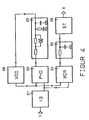
Die Funktion des Phasenregelkreises (Figur 1, Baueinheit 8) ist in Figur 4 weiter aufgeschlüsselt. Ein hochintegrierter Standardbaustein (40HC46) enthält einen spannungsgesteuerten Oszillator (VCO) 20 und einen flankengetriggerten Phasenkomparator (PHD) 22. Die Schaltung wird ergänzt durch eine Teilerstufe 21, ein Exclusiv-Oder-Gatter (XOR) 24, einen Tiefpass 25 und einen Schmitt-Trigger (ST) 26.The function of the phase locked loop (FIG. 1, module 8) is further broken down in FIG. A highly integrated standard module (40HC46) contains a voltage-controlled oscillator (VCO) 20 and an edge-triggered phase comparator (PHD) 22. The circuit is supplemented by a
Der Phasenregelkreis (PLL) arbeitet bei korrekter Dimensionierung des Schleifen-Filters 23 mit einem PI-Verhalten. Am Ausgang 9 werden als Ergebnis Impulsgruppen weitergeleitet, die als Tropfenvektoren au interpretieren sind. Mit dem Phasenregelkreis läßt sich die gewünschte Demodulator-Funktion und die Linearisierung in nahezu idealer Weise (und mit minimalem Bauteilaufwand) realisieren.The phase locked loop (PLL) works with a correct dimensioning of the
In Figur 5 ist abschließend dargestellt, welche unterschiedlichen Signale durch Weiterverarbeitung (Figur 1, Baueienheit 10) der Tropfenvektoren gewonnen werden. Mit Hilfe des Signals E1 werden die einzelnen Tropfenvolumina als kalibrierte Impulsketten zum Aufbau von Tropfenspektren ausgegeben. Ein positiver Impuls von Signal E2 stellt genau 1/100 mmWS dar, bei Signal E3 sind es jeweils 1/5 mmWS. Mit dem Signal E4 steht einen normierter Zählimpuls von 100 ms für jeden Tropfen - unabhängig von seiner Größe - zur Verfügung. Signal E5 verharrt nach jedem Tropfen genau 10 Minuten lang auf H-Pegel und kann daher als einfache Regenmeldung (Ja/Nein) herangezogen werden.Finally, FIG. 5 shows which different signals are obtained by further processing (FIG. 1, construction unit 10) of the drop vectors. With the aid of the signal E1, the individual drop volumes are output as calibrated pulse chains for building up drop spectra. A positive pulse from signal E2 represents exactly 1/100 mmWS, with signal E3 it is 1/5 mmWS. With signal E4, a standardized counting pulse of 100 ms is available for every drop - regardless of its size. Signal E5 remains at H level for exactly 10 minutes after each drop and can therefore be used as a simple rain message (yes / no).
Es ist in Fachkreisen hinreichend bekannt, daß die Regenmessung bei starkem Wind immer mit einem erheblichen Fehler behaftet ist (aerodynamischer Fehler). Aus diesem Grund werden bei erhöhten Genauigkeitsanforderungen spezielle Vorrichtungen zur Verringerung des Windeinflusses (Windbrecher) angewendet (NOR 87).It is well known in specialist circles that the rain measurement in strong winds is always associated with a considerable error (aerodynamic error). For this reason, special devices for reducing the influence of wind (wind breakers) are used for increased accuracy requirements (NOR 87).
Grundsätzlich werden für das erfindungsgemäße Meßverfahren bei Wind ähnliche Störfaktoren gefunden. Auch hier können spezielle Konstruktionen - z.B. in Form von Windleitblechen - um den Sensor herum gruppiert werden, mit dem Ziel, den aerodynamischen Fehler so weit wie möglich zu verringern. Wenn solche Konstruktionen asymmetrisch ausgelegt sind, kann mit einer richtungsspezifischen Wirkung zugleich die (durch Schrägstellung der Meßfläche 2 bedingte) Windrichtungs-Abhängigkeit kompensiert werden.Basically similar disturbance factors are found for the measurement method according to the invention in wind. Here too, special designs - for example in the form of wind deflectors - can be grouped around the sensor with the aim of reducing the aerodynamic error as much as possible. If such constructions are designed asymmetrically, the direction of the wind (depending on the inclination of the measuring surface 2) can be compensated with a direction-specific effect.
Eine besonders wirksame Methode zur Vermeidung von Windrichtungs-Fehlern ist auch die gleichzeitige Anwendung von zwei bis vier gleichartigen, jedoch in verschiedene Himmelsrichtungen zeigenden Meßflächen. Die einzelnen Sektoren einer solchen Mehrfach-Anordnung könnten beispielsweise auf jeweils einer (geneigten) Dachfläche eines pyramidenförmigen Grundkörpers angebracht sein (Janus-Kopf).A particularly effective method for avoiding wind direction errors is the simultaneous use of two to four measuring surfaces of the same type, but pointing in different directions. The individual sectors of such a multiple arrangement could, for example, be attached to a (sloping) roof surface of a pyramid-shaped base body (Janus head).
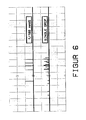
Abschließend soll die Leistungsfähigkeit des beschriebenen Beispiels anhand von charakteristischen Meßprotokollen dokumentiert werden. Figur 6 zeigt das Schreiberprotokoll eines isolierten, relativ kurzfristigen Niederschlagsereignisses. Die Dauer des Ereignisses war auf ca. sieben Minuten beschränkt. Während dieser Zeit wurden 22 einzelne Tropfen detektiert, die insgesamt abgeregnete Wassermenge betrug nur 0,05 mmWS.Finally, the performance of the example described should be documented using characteristic measurement protocols. FIG. 6 shows the recorder log of an isolated, relatively short-term precipitation event. The duration of the event was limited to approximately seven minutes. During this time, 22 individual drops were detected, the total amount of water that was rained down was only 0.05 mm water column.
Aus diesen Zahlen ergibt sich für das kurzfristige Ereignis eine (hochgerechnete) Niederschlagsaktivität von 0,43 mmWS pro Stunde. Zum Vergleich: Für Trichter-Meßverfahren muß mit einem Benetzungsverlust von ca. 0,26 mmWS pro Ereignis und mit einem Verdunstungsverlust von (durchschnittlich) 0,1 mmWS pro Tag gerechnet werden (KEL 79). Aus den letztgenannten Zahlen läßt sich auch abschätzen, daß ein in der Intensität vergleichbares Regen-ereignis mindestens eine halbe Stunde andauren müßte, bevor eine Tropfer/Wippe-Kombination erstmalig ansprechen kann.From these numbers, a (extrapolated) precipitation activity of 0.43 mmWS per hour results for the short-term event. For comparison: For funnel measurement methods, a loss of wetting of approx. 0.26 mm water column per event and an evaporation loss of (average) 0.1 mm water column per day must be expected (KEL 79). It can also be estimated from the latter figures that a rain event of comparable intensity would have to last at least half an hour before a dropper / seesaw combination can respond for the first time.
Figur 7 zeigt beispielhaft zwei Tropfengrößen-Verteilungen (Regentropfen-Spektren), die durch on-line-Auswertung der Tropfenvektoren mit Hilfe eines Computers gewonnen wurden. In den gezeigten Grafiken sind jeweils 100 aufeinanderfolgende Tropfen nach ihrem Volumen klassiert. Dabei sind insgesamt 40 Größenklassen dargestellt. Die Klassenbreite beträgt jeweils 0,2 µl. Der hier in der Grafik gezeigte Bereich überdeckt also Tropfenvolumina von 0,2 bis 8 µl.FIG. 7 shows, by way of example, two drop size distributions (raindrop spectra), which were obtained by online evaluation of the drop vectors using a computer. In the graphics shown, 100 consecutive drops are classified according to their volume. A total of 40 size classes are shown. The class width is 0.2 µl each. The area shown in the graphic covers drop volumes of 0.2 to 8 µl.
Links in Figur 7 ist das Spektrum eines feintröpfigen Nieselregens, rechts das Spektrum eines gerade einsetzenden Juni-Schauers (mit mittlerer Tropfengröße) zu sehen. Bei den hier dokumentierten Ereignissen wurden keine Tropfenvolumina oberhalb von 8 µl festgestellt - beim Auftreten größerer Volumina würde die grafische Darstellung automatisch bis auf 100 µl ausgedehnt.The spectrum of a fine drizzle of drizzle can be seen on the left in FIG. 7, and the spectrum of a June shower which is just beginning (with a medium droplet size) can be seen on the right. In the events documented here, no drop volumes above 8 µl were found - if larger volumes occurred, the graphical representation would automatically be expanded to 100 µl.
Aus der Fachliteratur (PRU 80) geht hervor, daß mit dem Arbeitsbereich des erfindungsgemäß ausgelegten Beispiels, d.h. von etwa 0,2 bis 100 µl pro Tropfen tatsächlich die in der Praxis dominierenden Tropfenvolumina gut abgedeckt sind. Mit diesem für mitteleuropäische Verhältnisse optimierten Regensensor kann lediglich Nebelnässen am unteren Ende des Spektrums und tropischer Monsunregen am oberen Ende des Spektrums nicht mehr korrekt erfaßt werden. Durch gezielte Anspassung der geometrischen Strukturen in die eine oder in die andere Richtung kann jedoch auch hier bei Bedarf noch Abhilfe geschaffen werden.The technical literature (PRU 80) shows that the working range of the example designed according to the invention, ie from about 0.2 to 100 μl per drop, actually covers the drop volumes that dominate in practice. With this rain sensor optimized for Central European conditions, only mist wetting at the lower end of the spectrum and tropical monsoon rain at the upper end of the spectrum can no longer be detected correctly. By adapting the geometric structures in one direction or in the other direction, remedial action can also be taken if necessary.
BAE 74 Baer J: Rain Gauge. US-Patentanmeldung 3,943,762 (1974)
BES 87 Best R: Theorie und Anwendungen des Phase-Locked Loop. AT-Verlag, Aarau/Stuttgart (1987)
DIN 58 666 Deutsches Institut für Normung e.V. (Hg.): Meteorologische Geräte, Niederschlags-Auffanggerät, 200 cm² Auffangfläche, Beuth Verlag, Berlin (1966)
DIN 58 667 Deutsches Institut für Normung e.V. (Hg.): Meteorologische Geräte, Niederschlags-Meßgefäß, Beuth Verlag, Berlin (1966)
DER 77 Derman KG, Linden U, Söderberg R: Regenmesser. Deutsche Offenlegungsschrift 26 41 393 (1977)
HAN 86 Hansen DF, Shubert WK: Anordnung und Verfahren zur Beobachtung gegenwärtiger Wettererscheinungen. Internationale Patentanmeldung PCT/US85/00718 und Deutsche Veröffentlichung DE 35 90 723 T1
HEI 82 Heicks R: Meßfühler für die Kontrolle des Benässungsgrades von Oberflüchen. Deutsche Gebrauchsmusteranmeldung G 82 34 131.1
JüL 81 Kernforschungsanlage Jülich GmbH: Regenfühler für einen Regensammler. Deutsche Gebrauchsmusteranmeldung G 81 21 939.3
KAH 72 Kahl G, Guidi GG: (zitiert aus NOR 87, Titel unbekannt), US-Patentanmeldung 3,705,533 (1972)
KEL 79 Keller R (Hg.): Hydrologischer Atlas der Bundesrepublik Deutschland/Textband. Harald Boldt Verlag, Boppart (1979), Seite 48 - 50
NEL 83 Nelson JA: Nonmechanical Digital Raingauge. US-Patentanmeldung 4,520,667 (1983)
NOR 87 Noren: Arrangement in Precipitation Gauges. Internationale Patentanmeldung PCT SE87/00077 (1987)
OEH 87 Oehme F: Was ist ein chemischer Sensor? In: Tagungsband Chemische und Bioochemische Sensoren. 3.-4. September 1987, Crest Hotel Friedrichsdorf im Taunus, Schirmherrschaft GDCh - Gesellschaft Deutscher Chemiker (Frankfurt), Verlag ACS Organisations GmbH, D-3050 Wunstorf 2, Seite 9 - 22
PRU 80 Pruppacher HR, Klett JD: Clouds and Precipitation. D.Reidel Publishing Company, Dordrecht/Boston/London (1980), Seite 22 - 27
REI 86 Reichl H: Hybridintegration. Hüthig Verlag, Heidelberg (1986), Seite 95 - 97
SCH 77 Schmitz L: Vorrichtung zur elektrischen Messung von Niederschlägen. Deutsche Patentanmeldung DE 27 20 602 C2 (1977)
TIE 83 Tietze U, Schenck C: Halbleiter-Schaltungstechnik. Springer Verlag, Berlin/Heidelberg/New York/ Tokyo (1983), Seite 817 -829
WAL 85 Walsh JE, Longacre JR: Precipitation Gauge. US-Patentanmeldung 4,538,399 (1985)
ZIE 87 Ziesemer M: Der industrielle Sensor. In: Chemie-Technik, Hüthig Verlag, Heidelberg (1987), 16. Jahrgang/Heft Nr. 2, Seite 46 - 50
BAE 74 Baer J: Rain Gauge. U.S. Patent Application 3,943,762 (1974)
BES 87 Best R: Theory and applications of the phase-locked loop. AT publishing house, Aarau / Stuttgart (1987)
DIN 58 666 German Institute for Standardization eV (ed.): Meteorological devices, precipitation collecting device, 200 cm² collecting area, Beuth Verlag, Berlin (1966)
DIN 58 667 German Institute for Standardization eV (ed.): Meteorological devices, precipitation measuring vessel, Beuth Verlag, Berlin (1966)
DER 77 Derman KG, Linden U, Söderberg D: rain gauge.
HAN 86 Hansen DF, Shubert WK: Arrangement and method for observing current weather phenomena. International patent application PCT / US85 / 00718 and German publication DE 35 90 723 T1
HEI 82 Heicks R: Sensor for checking the degree of wetting of surfaces. German utility model application G 82 34 131.1
JüL 81 Kernforschungsanlage Jülich GmbH: Rain sensor for a rain collector. German utility model application G 81 21 939.3
KAH 72 Kahl G, Guidi GG: (cited from NOR 87, title unknown), US patent application 3,705,533 (1972)
KEL 79 Keller R (ed.): Hydrological Atlas of the Federal Republic of Germany / text volume. Harald Boldt Verlag, Boppart (1979), pages 48-50
NEL 83 Nelson JA: Nonmechanical Digital Raingauge. U.S. Patent Application 4,520,667 (1983)
NOR 87 Noren: Arrangement in Precipitation Gauges. International patent application PCT SE87 / 00077 (1987)
OEH 87 Oehme Q: What is a chemical sensor? In: Conference proceedings chemical and bioochemical sensors. 3-4. September 1987, Crest Hotel Friedrichsdorf im Taunus, patronage GDCh - Gesellschaft Deutscher Chemiker (Frankfurt), publisher ACS Organizations GmbH, D-3050
PRU 80 Pruppacher HR, Klett JD: Clouds and Precipitation. D. Reidel Publishing Company, Dordrecht / Boston / London (1980), pages 22-27
REI 86 Reichl H: hybrid integration. Hüthig Verlag, Heidelberg (1986), pages 95-97
SCH 77 Schmitz L: Device for the electrical measurement of precipitation. German patent application DE 27 20 602 C2 (1977)
TIE 83 Tietze U, Schenck C: semiconductor circuit technology. Springer Verlag, Berlin / Heidelberg / New York / Tokyo (1983), pages 817-829
WAL 85 Walsh JE, Longacre JR: Precipitation Gauge. U.S. Patent Application 4,538,399 (1985)
ZIE 87 Ziesemer M: The industrial sensor. In: Chemie-Technik, Hüthig Verlag, Heidelberg (1987), 16th year / issue No. 2, pages 46 - 50
Claims (9)
dadurch gekennzeichnet,
daß einzelne auf einer Meßfläche 2 auftreffende Tropfen anhand ihrer Prallfläche 3 bewertet werden.1. Electronic sensor as a rain detector, for measuring integral amounts of rain or for determining individual droplet volumes,
characterized by
that individual drops hitting a measuring surface 2 are evaluated on the basis of their impact surface 3.
dadurch gekennzeichnet,
daß die hydrodynamischen Vorgänge beim Aufprall eines Tropfens auf einer Meßfläche 2 ein Primärsignal erzeugen, das kapazitiv abgekoppelt und mit Hilfe einer elektronischen Signalverarbeitung in das zugehörige Tropfenvolumen konvertiert wird.2. Electronic sensor according to claim 1,
characterized by
that the hydrodynamic processes when a drop impacts a measuring surface 2 generate a primary signal which is capacitively decoupled and converted into the associated drop volume with the aid of electronic signal processing.
dadurch gekennzeichnet,
daß die zur Bestimmung der Prallfläche 3 eingesetzte Meßfläche 2 mit Hilfe kammförmig oder spiralförmig ineinandergreifender Leiterstrukturen als Kondensator ausgebildet und daß dieser flächendeckend mit einem (nicht-leitenden) Dielektrikum überzogen ist.3. Electronic sensor according to claim 1 or 2,
characterized by
that the measuring surface 2 used to determine the baffle surface 3 is formed as a capacitor with the aid of comb-shaped or spiral-shaped intermeshing conductor structures and that this is covered with a (non-conductive) dielectric covering the entire surface.
dadurch gekennzeichnet,
daß zur größenmäßigen Bewertung der einzelnen Tropfen deren Prallfläche 3 primär mit Hilfe eines frequenzmodulierten Signals 7 bestimmt wird.4. Electronic sensor according to one of claims 1 to 3,
characterized by
that for the size evaluation of the individual drops their impact surface 3 is primarily determined with the aid of a frequency-modulated signal 7.
dadurch gekennzeichnet,
daß die Meßfläche 2 durch definierte Schrägstellung und in Verbindung mit einer speziellen Oberflächenbehandlung einen ausgeprägten Selbstreinigungseffekt besitzt.5. Electronic sensor according to one of claims 1 to 4,
characterized by
that the measuring surface 2 has a pronounced self-cleaning effect through defined inclination and in connection with a special surface treatment.
dadurch gekennzeichnet,
daß die exakte Umsetzung der primären Prallflächen-Bewertung in das gesuchte Tropfenvolumen (Tropfenvektor) durch eine Kombination unterschiedlich gestalteter Teilbereiche (Zonen) auf der Meßfläche 2 geschieht.6. Electronic sensor according to one of claims 1 to 5,
characterized by
that the exact conversion of the primary impact surface evaluation into the desired drop volume (drop vector) takes place by a combination of differently designed partial areas (zones) on the measuring surface 2.
dadurch gekennzeichnet,
daß die Umsetzung der primären Prallflächen-Bewertung in das gesuchte Tropfenvolumen (Tropfenvektor) mit Hilfe eines Phasenregelkreises (Phase- Locked Loop, PLL) geschieht.7. Electronic sensor according to one of claims 1 to 6,
characterized by
that the conversion of the primary impact surface evaluation into the desired drop volume (drop vector) takes place with the aid of a phase locked loop (PLL).
dadurch gekennzeichnet,
daß der aerodynamische Fehler bei der Regenmessung durch ein richtungsspezifisch wirkendes Windleitblech verringert wird.8. Electronic sensor according to one of claims 1 to 7,
characterized by
that the aerodynamic error in the rain measurement is reduced by a direction-specific wind deflector.
dadurch gekennzeichnet,
daß der aerodynamische Fehler bei der Regenmessung durch eine sektorenweise, z.B. pyramidenförmige, gleichzeitig in mehrere Himmelsrichtungen zeigende Meßfläche 2 verringert wird.9. Electronic sensor according to one of claims 1 to 7,
characterized by
that the aerodynamic error in the rain measurement is reduced by a sector-by-area, for example pyramid-shaped, measurement surface 2 pointing simultaneously in several directions.
Priority Applications (1)
| Application Number | Priority Date | Filing Date | Title |
|---|---|---|---|
| EP88115906A EP0360892A1 (en) | 1988-09-27 | 1988-09-27 | Electronic sensor for measuring rainfall by evaluating the impact surface of single drops |
Applications Claiming Priority (1)
| Application Number | Priority Date | Filing Date | Title |
|---|---|---|---|
| EP88115906A EP0360892A1 (en) | 1988-09-27 | 1988-09-27 | Electronic sensor for measuring rainfall by evaluating the impact surface of single drops |
Publications (1)
| Publication Number | Publication Date |
|---|---|
| EP0360892A1 true EP0360892A1 (en) | 1990-04-04 |
Family
ID=8199377
Family Applications (1)
| Application Number | Title | Priority Date | Filing Date |
|---|---|---|---|
| EP88115906A Withdrawn EP0360892A1 (en) | 1988-09-27 | 1988-09-27 | Electronic sensor for measuring rainfall by evaluating the impact surface of single drops |
Country Status (1)
| Country | Link |
|---|---|
| EP (1) | EP0360892A1 (en) |
Cited By (12)
| Publication number | Priority date | Publication date | Assignee | Title |
|---|---|---|---|---|
| WO2003027719A1 (en) * | 2001-09-24 | 2003-04-03 | Vaisala Oyj | Precipitation sensor and method for precipitation rate measurement |
| WO2003027720A1 (en) * | 2001-09-24 | 2003-04-03 | Vaisala Oyj | Precipitation/hail sensor and method for precipitation rate measurement |
| CN100357712C (en) * | 2005-08-04 | 2007-12-26 | 上海大学 | Supersonic metering method and device for liquid drop |
| CN100432704C (en) * | 2004-10-27 | 2008-11-12 | 上海大学 | Multi-parameter detecting method and apparatus for liquid drop |
| US8714007B2 (en) | 2011-04-29 | 2014-05-06 | Airmar Technology Corporation | Precipitation sensor |
| DE102012023188A1 (en) * | 2012-11-28 | 2014-05-28 | Carbon Team Germany Gmbh | Device for measuring presence of raindrops under usage of inclined plane, over which raindrops flow down, has sensor producing signal during presence of rain drop, and electrical sensor arranged in electric circuit |
| DE102015209601A1 (en) | 2015-05-26 | 2016-12-01 | Volkswagen Aktiengesellschaft | Method and system for determining a rainfall |
| RU2620168C1 (en) * | 2016-05-11 | 2017-05-23 | Федеральное государственное бюджетное образовательное учреждение высшего образования "Московский государственный университет имени М.В. Ломоносова" (МГУ) | Device for counting number of drops |
| IT201600077834A1 (en) * | 2016-07-25 | 2018-01-25 | Cristiano Fidani | ELECTRODYNAMIC RAIN GAUGE |
| CN109917490A (en) * | 2019-04-03 | 2019-06-21 | 南京信息工程大学 | A kind of hail automated watch-keeping facility |
| CN112881646A (en) * | 2021-01-11 | 2021-06-01 | 西北农林科技大学 | Method for measuring flow resistance of slope surface thin layer influenced by raindrops striking |
| EP3995867A1 (en) * | 2020-11-10 | 2022-05-11 | Adolf Thies GmbH & Co. KG | Method and device for detecting subcooled liquid precipitate |
Citations (6)
| Publication number | Priority date | Publication date | Assignee | Title |
|---|---|---|---|---|
| FR1322873A (en) * | 1962-02-09 | 1963-04-05 | Commissariat Energie Atomique | Atmospheric fallout collector |
| DE2031373A1 (en) * | 1970-06-25 | 1972-01-05 | Beuttenmueller A | Method and arrangement for detecting an electrically conductive substance |
| FR2250122A1 (en) * | 1973-11-05 | 1975-05-30 | Surface Systems | |
| DE8121939U1 (en) * | 1981-07-25 | 1982-01-14 | Kernforschungsanlage Jülich GmbH, 5170 Jülich | RAIN SENSOR FOR A RAIN COLLECTOR |
| DE8234131U1 (en) * | 1982-12-04 | 1983-06-16 | Heicks, Rudolf, 4190 Kleve | MEASURING PROBE FOR CONTROLLING THE WATER DEGREE OF SURFACES |
| FR2557369A1 (en) * | 1983-10-24 | 1985-06-28 | Pagnol Frederic | DEVICE FOR PANELS OR PHOTOVOLTAIC CELLS, GROUPED IN SECTIONS ON A CONE-SHAPED CARRIER, CONE TRUNK OR N-CUT PYRAMID TRUNK |
-
1988
- 1988-09-27 EP EP88115906A patent/EP0360892A1/en not_active Withdrawn
Patent Citations (6)
| Publication number | Priority date | Publication date | Assignee | Title |
|---|---|---|---|---|
| FR1322873A (en) * | 1962-02-09 | 1963-04-05 | Commissariat Energie Atomique | Atmospheric fallout collector |
| DE2031373A1 (en) * | 1970-06-25 | 1972-01-05 | Beuttenmueller A | Method and arrangement for detecting an electrically conductive substance |
| FR2250122A1 (en) * | 1973-11-05 | 1975-05-30 | Surface Systems | |
| DE8121939U1 (en) * | 1981-07-25 | 1982-01-14 | Kernforschungsanlage Jülich GmbH, 5170 Jülich | RAIN SENSOR FOR A RAIN COLLECTOR |
| DE8234131U1 (en) * | 1982-12-04 | 1983-06-16 | Heicks, Rudolf, 4190 Kleve | MEASURING PROBE FOR CONTROLLING THE WATER DEGREE OF SURFACES |
| FR2557369A1 (en) * | 1983-10-24 | 1985-06-28 | Pagnol Frederic | DEVICE FOR PANELS OR PHOTOVOLTAIC CELLS, GROUPED IN SECTIONS ON A CONE-SHAPED CARRIER, CONE TRUNK OR N-CUT PYRAMID TRUNK |
Non-Patent Citations (1)
| Title |
|---|
| PATENT ABSTRACTS OF JAPAN, Band 9, Nr. 157 (P-369)[1880], 2. Juli 1985; & JP-A-60 33 078 (TATEISHI DENKI K.K.) 20-02-1985 * |
Cited By (17)
| Publication number | Priority date | Publication date | Assignee | Title |
|---|---|---|---|---|
| WO2003027719A1 (en) * | 2001-09-24 | 2003-04-03 | Vaisala Oyj | Precipitation sensor and method for precipitation rate measurement |
| WO2003027720A1 (en) * | 2001-09-24 | 2003-04-03 | Vaisala Oyj | Precipitation/hail sensor and method for precipitation rate measurement |
| US7249502B2 (en) | 2001-09-24 | 2007-07-31 | Vaisala Oyj | Precipitation/hail sensor and method for precipitation rate measurement |
| CN100432704C (en) * | 2004-10-27 | 2008-11-12 | 上海大学 | Multi-parameter detecting method and apparatus for liquid drop |
| CN100357712C (en) * | 2005-08-04 | 2007-12-26 | 上海大学 | Supersonic metering method and device for liquid drop |
| US8714007B2 (en) | 2011-04-29 | 2014-05-06 | Airmar Technology Corporation | Precipitation sensor |
| US9244192B2 (en) | 2011-04-29 | 2016-01-26 | Airmar Technology Corporation | Precipitation sensor |
| DE102012023188A1 (en) * | 2012-11-28 | 2014-05-28 | Carbon Team Germany Gmbh | Device for measuring presence of raindrops under usage of inclined plane, over which raindrops flow down, has sensor producing signal during presence of rain drop, and electrical sensor arranged in electric circuit |
| DE102015209601A1 (en) | 2015-05-26 | 2016-12-01 | Volkswagen Aktiengesellschaft | Method and system for determining a rainfall |
| DE102015209601B4 (en) | 2015-05-26 | 2022-12-08 | Volkswagen Aktiengesellschaft | Method and system for determining an amount of rain |
| RU2620168C1 (en) * | 2016-05-11 | 2017-05-23 | Федеральное государственное бюджетное образовательное учреждение высшего образования "Московский государственный университет имени М.В. Ломоносова" (МГУ) | Device for counting number of drops |
| IT201600077834A1 (en) * | 2016-07-25 | 2018-01-25 | Cristiano Fidani | ELECTRODYNAMIC RAIN GAUGE |
| CN109917490A (en) * | 2019-04-03 | 2019-06-21 | 南京信息工程大学 | A kind of hail automated watch-keeping facility |
| CN109917490B (en) * | 2019-04-03 | 2023-10-31 | 南京信息工程大学 | Hail automatic monitoring device |
| EP3995867A1 (en) * | 2020-11-10 | 2022-05-11 | Adolf Thies GmbH & Co. KG | Method and device for detecting subcooled liquid precipitate |
| WO2022101099A1 (en) * | 2020-11-10 | 2022-05-19 | Adolf Thies Gmbh & Co. Kg | Method and device for detecting freezing liquid precipitation |
| CN112881646A (en) * | 2021-01-11 | 2021-06-01 | 西北农林科技大学 | Method for measuring flow resistance of slope surface thin layer influenced by raindrops striking |
Similar Documents
| Publication | Publication Date | Title |
|---|---|---|
| EP0360892A1 (en) | Electronic sensor for measuring rainfall by evaluating the impact surface of single drops | |
| DE3590723C2 (en) | ||
| DE19513274C2 (en) | Method of measuring dew point or gas concentration and device for predicting icing | |
| DE3438332C2 (en) | ||
| Eder | A principal component analysis of SO2− 4 precipitation concentrations over the eastern United States | |
| WO1999027325A2 (en) | Thermal membrane sensor and method for the production thereof | |
| EP0742763A1 (en) | Device for operating a windscreen wiper in intermittent and continuous modes | |
| WO2011128271A1 (en) | Corrosion detection apparatus for monitoring a state of corrosion | |
| Beck | Generation of spatially correlated synthetic rainfall time series in high temporal resolution: a data driven approach. | |
| DE102005003970A1 (en) | Sensor arrangement`s operability determining method for motor vehicle, involves detecting sensor signals successively for different sub-regions while passing at surrounding region, and determining number of measuring events in latter region | |
| Sloane | Meteorologically adjusted air quality trends: visibility | |
| EP0384209B1 (en) | Method for the operation of an ionization smoke detector, and ionization smoke detector | |
| DE4025184C2 (en) | ||
| DE102005006861A1 (en) | Sensor element e.g. for detecting rain on vehicle etc., has resonant circuit with additional electronic device such as temperature or pressure-sensitive device arranged on substrate | |
| DE102004000025B4 (en) | System and method for detecting, transmitting and evaluating electromagnetic radiation data and information | |
| DE102013019839B4 (en) | Passive temperature sensor, operation and manufacture of the sensor | |
| DE3045980A1 (en) | SLOPE AND SLOPE MEASURING DEVICE FOR VEHICLES | |
| DE102004000024B4 (en) | System and method for detecting, transmitting and evaluating electromagnetic radiation data and information | |
| DE10202198A1 (en) | Device for measuring matrix potential in material comprises unit for measuring water content, and reference body made from fibers and in contact with measured object | |
| DE2453846C2 (en) | ARRANGEMENT FOR FAST DETECTION OF FLIGHT MANEUVERS | |
| Uijlenhoet et al. | Towards a stochastic model of rainfall for radar hydrology: Testing the Poisson homogeneity hypothesis | |
| DE102005045463B4 (en) | Measuring arrangement for radiation detection under vacuum conditions | |
| WO1998009151A1 (en) | Process and device for determining the volume of liquid droplets | |
| DE4308132C2 (en) | Miniaturized sensor | |
| EP0777130A2 (en) | Digital method for detecting temporally short pulses, and device for performing the method |
Legal Events
| Date | Code | Title | Description |
|---|---|---|---|
| PUAI | Public reference made under article 153(3) epc to a published international application that has entered the european phase |
Free format text: ORIGINAL CODE: 0009012 |
|
| AK | Designated contracting states |
Kind code of ref document: A1 Designated state(s): CH DE FR GB LI NL SE |
|
| RBV | Designated contracting states (corrected) |
Designated state(s): DE FR GB |
|
| 17P | Request for examination filed |
Effective date: 19901004 |
|
| 17Q | First examination report despatched |
Effective date: 19911106 |
|
| STAA | Information on the status of an ep patent application or granted ep patent |
Free format text: STATUS: THE APPLICATION IS DEEMED TO BE WITHDRAWN |
|
| 18D | Application deemed to be withdrawn |
Effective date: 19930310 |